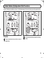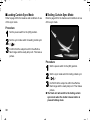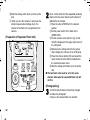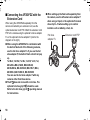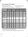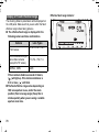
1
01_Cover_1.fm Page 0 Tuesday, June 13, 2006 12:08 PM AUTO ZOOM ELECTRONIC FLASH UNIT OPERATING MANUAL Please read this operating manual carefully first for proper use. 00_AF360FGZ.book Page 0 Tuesday, June 13, 2006 12:09 PM Thank you for purchasing the PENTAX Auto-flash AF360FGZ. In addition to easy daylight sync photography with TTL auto, the AF360FGZ also allows wireless TTL auto (P-TTL auto) photography and high-speed sync. It is clip-on type flash which enables accurate focus adjustments even in dark locations with built-in AF-assist spotbeam. Bundled Items The following items are supplied with this product. Check that all the items have been included before use. l Case l Operating manual (this manual) l Certification PENTAX is a trademark of PENTAX Corporation. 00_AF360FGZ.book Page 1 Tuesday, June 13, 2006 12:09 PM FOR SAFE USE OF YOUR FLASH UNIT Although we have carefully produced this flash unit for safe operation, please be sure to especially follow warnings and cautions given on page 2. WARNING This mark indicates precautions that, if not followed, could result in serious injury to the user. CAUTION This mark indicates precautions that, if not followed, could result in minor or medium injury to the user or damage to the equipment. is a symbol indicating items that are prohibited. is a symbol emphasizing a warning. 1 00_AF360FGZ.book Page 2 Tuesday, June 13, 2006 12:09 PM WARNING CAUTION The flash contains electronic circuits that operate at high voltages. Do not attempt to disassemble the flash unit yourself, as there is danger of an electric shock. Do not use the flash near anyone’s eyes, as it may hurt them. Be particularly careful with the flash around infants. If internal parts of the flash unit becomes exposed due to impact, etc., do not touch them as there is danger of an electric shock. Do not expose the flash unit to water or moisture as there is danger of an electric shock. 2 The following may lead to an explosion or fire. l Shorting the batteries l Exposing the batteries to flames l Dismantling the batteries l Attempting to recharge non-rechargeable batteries Remove the batteries from the camera immediately if they become hot or begin to smoke. Be careful not to burn yourself during removal. 00_AF360FGZ.book Page 3 Tuesday, June 13, 2006 12:09 PM Precautions for Your Flash Unit l Never use organic solvents such as paint thinner, alcohol or benzene to clean the flash unit. l Avoid leaving the flash unit for extend period in places where the humidity and temperature are very high such as in a car. l Be careful not to subject the flash unit to strong vibrations, shock or pressure. Use a cushion to protect the flash unit when carrying it in a motorcycle, car, boat, etc. l Do not use the flash unit where it may be directly exposed to rain water etc. l When using the flash unit off the camera, do not try to attach any metallic object to the electric contacts or to mount incompatible accessories. Otherwise, the TTL auto mechanism may be damaged or rendered inoperable. l Periodic checks are recommended every 1 to 2 years in order to maintain high performance. If the unit has not been used for an extended period of time, or is being readied for an important shoot, it is recommended that you take a test flash with the test button and test shoot with it. Test flash is also important to maintain optimum performance. l Avoid contact with garbage, dirt, sand, dust, water, toxic gases, salt, etc. When the flash unit is subjected to rain or moisture, wipe it off with a dry soft. l When photographing black subjects or white subjects, use exposure compensation. l Do not attach any accessories having the wrong number of electrical contacts for the hot shoe or grip. Otherwise, some functions may not work properly. l Pentax will not be held responsible for any accidents or damage, etc. caused due to the use of this product with cameras which are made by companies other than Pentax. 3 00_AF360FGZ.book Page 4 Tuesday, June 13, 2006 12:09 PM nCautions Regarding Batteries l This flash unit uses 4 AA-size alkaline, lithium, or nickel metal hydride batteries. Do not use any other type of batteries. The flash unit may not be able to operate correctly or demonstrate sufficient performance, or the flash unit itself may generate heat, depending on the type of batteries used. l AA-size alkaline and lithium batteries themselves are not rechargeable. Also, do not dismantle the batteries. Trying to recharge or dismantle these batteries may cause an explosion or leakage. l When changing batteries, do not mix batteries of different manufacturers, type and capacity. l Do not insert the batteries with the positive (+) and negative (-) terminals the wrong way around. Incorrect insertion may lead to an explosion or fire. l Battery performance may temporarily be hindered in low temperatures. Batteries should be kept warm in temperatures below freezing for proper performance. l If you do not intend to use the flash unit for an extended period of time, remove the batteries. Leaving the batteries in may cause damage to the flash unit due to leakage etc. 4 00_AF360FGZ.book Page 5 Tuesday, June 13, 2006 12:09 PM Table of Contents FOR SAFE USE OF YOUR FLASH UNIT ........... 1 Precautions for Your Flash Unit ....................... 3 Cautions Regarding Batteries............................. 4 Names of Parts ................................................... 6 LCD Panel Indicator............................................ 8 Inserting the Batteries ..................................... 10 Mounting to Camera......................................... 12 Turning the Power On...................................... 13 Auto Power Off Function................................... 14 Quick Power On Function................................. 14 Select Button (S)/Adjustment Dial Functions............................................... 15 Camera Format and Flash Coverage Angle ............................................ 17 Using the Flash Modes .................................... 22 P-TTL Auto Flash.............................................. TTL Auto Flash ................................................. Auto Flash......................................................... Manual Flash .................................................... 23 24 25 27 Using the Sync Mode ....................................... 29 Leading Curtain Sync Mode ............................. Trailing Curtain Sync Mode .............................. High-Speed Sync Mode.................................... Contrast Control Sync Flash............................. 30 30 31 33 Advanced Functions ........................................ 35 Wireless Mode .................................................. Slave................................................................. Slave Mode Setting........................................... Slow-Speed-Sync Photography ........................ Bounce Flash.................................................... AF Spotbeam.................................................... Wide-Angle Panel and Catchlight Panel ........... Modeling Flash/Test Flash................................ Connecting the AF360FGZ with the Extension Cord ............................................. 35 47 49 50 51 53 54 55 56 Supported Functions for Pentax Cameras .... 57 Cameras that Support Each Flash Mode.......... Cameras that Support Each Sync Mode .......... Cameras that Support Wireless Mode .............. Cameras that Support Slow-Speed-Sync Mode............................................................. Functions Related to Each Flash Mode ............ Sync Mode Restrictions .................................... Precautions When Photographing with a Slave Flash ................................................... 57 59 60 61 61 69 76 Flash Effective Range ...................................... 77 Calculating the Flash Effective Range .............. 77 Guide Number (GN).......................................... 79 P-TTL and TTL Auto Flash Effective Range ..... 82 Optional Accessories....................................... 84 Specifications ................................................... 85 Warranty Policy ................................................ 88 5 00_AF360FGZ.book Page 6 Tuesday, June 13, 2006 12:09 PM Names of Parts 6 Bounce angle adjustment LCD panel Flash mode button Select button Adjustment dial LCD panel illumination button/ Format button Zoom button/ Channel button Test button/ Modeling button/ Ready lamp Setting switch Power switch Wireless mode switch Sync mode switch Bounce lock release button Battery chamber cover Shoe lock pin Flash signal contacts Shoe bracket Locking lever Wide-angle panel Catchlight panel AF spotbeam emitter Auto flash sensor Flash head Wireless sensor 00_AF360FGZ.book Page 7 Tuesday, June 13, 2006 12:09 PM > S @ V Y G T [ W R K Q " 7 00_AF360FGZ.book Page 8 Tuesday, June 13, 2006 12:09 PM nLCD Panel Indicator Zoom indicator : A.Zoom Ý M.Zoom xxmm = 20, 24, 28, 35, 50, 70, 85 (35 mm format) 35, 45, 55, 70, 100, 135, 150 (645 format) 55, 60, 70, 90, 120, 180, 190 (67 format) 13, 16, 19, 24, 34, 48, 58 (Digital camera) Format indicator : 35mm Ý 645 Ý 67 Flash mode indicator : P-TTL Ý A Ý M Ý SB Flash exposure compensation indicator : -3.0 to +1.0 steps, 0.5 step increments ISO indicator : ISO 25 to 1600 Bar graph Effective flash range indicator : Minimum distance - Maximum distance (in P-TTL, TTL, A modes) Minimum distance (in manual mode) AF spotbeam : SB Sync mode indicator : Bounce flash warning : Flash output adjustment indicator : NN/ X X f/stop (Leading curtain sync) (Trailing curtain sync) control sync) (High-speed sync) : F2 to F22 (When set to ISO 100) Channel indicator : 1 to 4CH Wireless mode indicator : MASTER, CONTROL, SLAVE 8 (Contrast 00_AF360FGZ.book Page 9 Tuesday, June 13, 2006 12:09 PM > @ When in poorly lit locations and the LCD panel cannot be seen, pressing the LCD panel illumination button (LIGHT) will illuminate the panel for about 10 seconds. Pressing it again will turn off the illumination. l The camera's LCD panel lights up also when you press the LCD illumination button (LIGHT) and the exposure metering timer is on for the following camera. MZ-S Auto Check Display If the correct flash output is obtained, the flash mode indicator and ( ) in the viewfinder will begin blinking. If the auto check display does not blink, the flash output is insufficient. Verify the effective flash range (refer to page 77) and adjust the distance to the subject, or open the aperture further. Even if the auto check display is blinking, the flash output may be incorrect if the subject is too close. l Depending on the combination of flash mode and camera, the auto check display may not display correctly 9 00_AF360FGZ.book Page 10 Tuesday, June 13, 2006 12:09 PM Inserting the Batteries 1 10 Slide the battery chamber cover as shown in the figure to open. 2 Insert four AA-size batteries, making sure the plus/minus marking (+, -) match the diagram inside the battery chamber cover. 00_AF360FGZ.book Page 11 Tuesday, June 13, 2006 12:09 PM Types of Batteries This flash unit uses four AA-size batteries of the same type, as shown below. - Alkaline battery (LR6) - Lithium battery (FR6) - Nickel-Metal Hydride battery (Ni-MH) (Nickel manganese (Ni-Mn) and nickel cadmium (NiCd) batteries cannot be used.) l For information about recycling times and total number of flashes, refer to “Specifications” on page 85. l If the indicators on the LCD panel or the ready lamp does not light up, the batteries may be exhausted or not inserted correctly. Verify the orientation of the batteries or, if the indicators and ready lamp still do not light up, replace them with new batteries. l If you let the flash unit fire successively using lithium batteries, the batteries will overheat, activating a safety circuit that temporarily disables the flash unit. If this occurs, rest the flash unit so that the temperature of the batteries returns to normal. 11 00_AF360FGZ.book Page 12 Tuesday, June 13, 2006 12:09 PM Mounting to Camera 1 1 2 12 2 Remove the hot shoe cover from the camera. Attach the flash unit to the camera. Turn the locking lever of the flash unit in the direction opposite to that indicated by (FIXÝ) (clockwise from the direction of the LCD panel). Slide the hot shoe bracket of the flash unit into the camera's hot shoe from the back of the camera forward. Turn the locking lever of the flash unit in the direction indicated by (FIXÝ) to lock it. l The following cameras have a shoe lock pin. When attaching the flash unit, turn the locking lever in the (FIXÝ) direction and lock the flash unit to the camera with the shoe lock pin. When releasing the flash unit, be sure to do so after turning the locking lever in the direction opposite to that indicated by (FIXÝ) and loosening the shoe lock pin. Otherwise, the hot shoe will be damaged. *ist D series, *ist, MZ-S, MZ-L/ZX-L/MZ-6, MZ-60/ZX-60 l The 672 does not come with a hot shoe. The optional hot shoe grip 672 should be used. 00_AF360FGZ.book Page 13 Tuesday, June 13, 2006 12:09 PM Turning the Power On Sliding the power switch to the (ON) position will turn on the power. The ready lamp will light up when the flash is charged. Sliding it to the (OFF) position will turn off the power. If charging time takes more than 20 seconds, the batteries have been exhausted and should be replaced with new batteries. If the flash unit is used with exhausted batteries, the settings may return to their default configuration. œŦŢťźġŭŢŮű l Turn the camera on before turning the flash unit on. l The WIRELESS position of the power switch is used for wireless mode and slave flash lighting. For details, see the explanations for each function. Ý Wireless mode (Page 35 - 46) Ý Slave flash (Page 47 - 48) 13 00_AF360FGZ.book Page 14 Tuesday, June 13, 2006 12:09 PM nAuto Power Off Function When the flash unit is left unused for about 3 minutes with the power switch set to the (ON) position, it automatically turns off to save the power. l In the auto flash mode (A), the power will turn off after about 6 minutes. l In the wireless mode, the power will turn off after about 1 hour of non-operation. nQuick Power On Function If the flash unit is mounted on the autofocus cameras, press the shutter release button half way to turn on the power. 14 00_AF360FGZ.book Page 15 Tuesday, June 13, 2006 12:09 PM Select Button (S)/Adjustment Dial Functions 4 types of settings are available as shown on the following pages for the select button (S) and the adjustment dial. Procedure 1 Press the select button (S) so that the number to adjust blinks. 2 Turn the adjustment dial and adjust the blinking number. 15 00_AF360FGZ.book Page 16 Tuesday, June 13, 2006 12:09 PM 3 After adjustment, press the select button (S) and stop the blinking. Adjust the other items below using the same procedure. l When using multiple flash units set to P-TTL or TTL Auto and adjusting the amount of light at the same time, use the camera’s exposure compensation. Connected Flash Mode Adjustment Range Flash exposure compensation P-TTL Auto flash -3.0 to +1.0 levels (EV) (0.5 step increments) ISO / F (aperture) setting Auto flash (A) ISO 25 to ISO 1600, F2 to F22 (with ISO100) Manual flash output Manual (M) 1/1, 1/2, 1/4, 1/8, 1/16, 1/32 Flash output setting Wireless (W) master flash (M) Wireless (W) slave flash (S) 1/1, 2/3, 1/2, 1/3 16 00_AF360FGZ.book Page 17 Tuesday, June 13, 2006 12:09 PM Camera Format and Flash Coverage Angle The AF360FGZ’s flash coverage angle can be adjusted to match the angle of view of the lens being used, which enables effective distribution of the flash light. The flash coverage angle is indicated by the focal lengths of available lenses in the LCD panel of the flash unit, according to the preset image size (FORMAT) of the camera. 1 Format setting Firstly, set the FORMAT to match the image size of the camera you are using. The format size will automatically be set when the shutter release button is pressed halfway down when the AF360FGZ is used in combination with the following cameras. *ist, MZ-S, MZ-L/ZX-L/MZ-6, *ist DL2, *ist DS2, *ist DL, *ist DS, *ist D For other cameras, before use, set the FORMAT to match the image size of the camera according to the following procedure. Slide the setting switch down (yellow dot). Press the FORMAT button repeatedly to display camera formats (image sizes) in the LCD panel. You can switch from 35mm Ý 645 Ý 67 Ý 35mm in that order. 17 00_AF360FGZ.book Page 18 Tuesday, June 13, 2006 12:09 PM 2 Zoom position (Flash coverage angle) setting Next, set the zoom (flash coverage angle) to match the focal length of the lens you are using. Auto Zoom (A.Zoom) If both the camera and lens are autofocus, you can automatically set the flash coverage angle according to the focal length of the lens by pressing the shutter release button of the camera halfway down. The auto zoom function operates while the exposure meter is operating (while information is being displayed in the viewfinder). 18 If you are setting the format manually, return the setting switch to the upper (white dot) position. When (M.Zoom) is displayed on the LCD panel, press the zoom button (ZOOM) repeatedly until (A.Zoom) is displayed. l When the flash mode is set to auto flash, the auto zoom function does not operate even if the camera and lens are both autofocus. Set the zoom manually to match the lens angle of view. Manual Zoom (M.Zoom) If one or both of the camera and lens are manual focus, you must set the flash coverage angle manually. If you are setting the format manually, return the setting switch to the upper (white dot) position. Press the zoom button (ZOOM) until the focal length of the lens being used is displayed on the LCD panel or if it can not be displayed exactly one wider than the lens focal length. The zoom position is switched in the order shown in the diagram on page 20. 00_AF360FGZ.book Page 19 Tuesday, June 13, 2006 12:09 PM Zoom Positions by Camera format * With the wide-angle panel 35mm camera 645 camera 67 camera Digital camera 20mm* 35mm* 55mm* 13mm* 24mm 45mm 60mm 16mm 28mm 55mm 70mm 19mm 35mm 70mm 90mm 24mm 50mm 100mm 120mm 34mm 70mm 135mm 180mm 48mm 85mm 150mm 190mm 58mm l When the wide-angle panel is used, the zoom button (ZOOM) will not work. (The wide-angle panel is in a slit on the top of the flash head. Pull it out so that it covers the front of the flash head. If the catchlight panel is not necessary, leave it in the slit.) 19 00_AF360FGZ.book Page 20 Tuesday, June 13, 2006 12:09 PM 35mm Camera 20 645 Camera 67 Camera Digital Camera 00_AF360FGZ.book Page 21 Tuesday, June 13, 2006 12:09 PM l In the (A.Zoom) mode, the flash coverage angle will be adjusted automatically to suit the lens focal length when you press the shutter release button halfway, and the camera exposure metering timer is on. l A warning signal appears as follows when the flash cannot cover the focal length of the camera. - The zoom indicator blinks for the combination of the following camera and lenses. Camera l In the (A.Zoom) mode, if there is no lens focal length information, the flash coverage angle will be set automatically to 24mm with a 35mm camera and digital camera. With a 645 camera, it will be set to 45mm, with a 67 camera it will be 60mm. l When using the wide-angle panel, the angle will be fixed at 20 mm for a 35 mm camera, 35 mm for a 645 camera, 55 mm for a 67 camera, and 13 mm for a digital camera in both A.Zoom and M.Zoom. Lens Types *ist D series DA, D FA, FA J, FA, F 35mm autofocus single lens reflex cameras D FA, FA J, FA, F 645N2, 645N FA645 - The warning signal does not appear for the combination of the following cameras and focal lengths. Camera Focal length *ist, MZ-L/ZX-L/MZ-6, MZ-S 20 mm and over, less than 24 mm *ist DL, *ist DS, *ist D 13 mm and over, less than 16 mm 21 00_AF360FGZ.book Page 22 Tuesday, June 13, 2006 12:09 PM Using the Flash Modes The AF360FGZ has the following flash modes. Select the mode best suited for the subject. Before photographing, confirm the following. 1. Whether your camera supports the desired flash mode. Ý Cameras that Support Each Flash Mode (Page 57) 2. Whether you can use the desired function with the combination of your camera and the flash mode you have set. Ý Functions Related to Each Flash Mode (Page 61 - 68) TTL auto flash (TTL) P-TTL auto flash (P-TTL) When the camera is set to manual exposure, manual flash can be set to suit the subject distance and aperture. The manual flash output can be set to 1/1, 1/2, 1/4, 1/8, 1/16, or 1/32. Refer to page 27 for instructions on how to use this flash mode. A pre-flash is fired before the main flash so that the multi-segment metering sensor can measure the subject's distance, brightness, brightness difference, backlit condition, etc. The data obtained is incorporated to set the output of the main flash. This mode obtains more accurate results than with the conventional TTL mode. Refer to page 23 for instructions on how to use this flash mode. 22 Based on the amount of light reflected off the film of the camera, the camera adjusts the flash output automatically to obtain a correct exposure. Refer to page 24 for instructions on how to use this flash mode. Auto flash (A) The built-in flash metering sensor adjusts the flash output automatically. Use with cameras that are not PTTL or TTL Auto flash compatible. Refer to page 25 for instructions on how to use this flash mode. Manual flash (M) 00_AF360FGZ.book Page 23 Tuesday, June 13, 2006 12:09 PM 3 nP-TTL Auto Flash Set the sync mode switch to leading curtain sync ( ), trailing curtain sync ( ), or contrast-control ( ), according to the subject. (Refer to page 29.) l After turning the power (ON), the setting will be (P-TTL) and (A.Zoom). EffectiveFlash range Refer to page 22 for the features and conditions of use of this flash mode. Procedure 1 2 Turn on the flash unit. Press the flash mode button (MODE) until (P-TTL) is displayed on the LCD panel. 4 5 Set the zoom position. (The setting method differs according to your camera and lens. Refer to page 18.) Confirm that the subject is within the effective flash range and the ready lamp is lit. Then take a picture. l In the following cameras, if the correct flash output is obtained, the flash mode indicator and ( ) in the viewfinder will blink. *ist, MZ-S, MZ-L/ZX-L/MZ-6 For details, refer to “Auto Check Display” on page 9. l The correct flash output is obtained in P-TTL auto mode only when the flash unit is used with autofocus lenses. l If necessary, an exposure compensation amount can be set between +1.0 to -3.0 steps in 0.5-step increments. (Refer to page 15.) 23 00_AF360FGZ.book Page 24 Tuesday, June 13, 2006 12:09 PM nTTL Auto Flash Procedure Refer to page 22 for the features and conditions of use of this flash mode. 24 1 2 3 4 5 Turn on the flash unit. Press the flash mode button (MODE) until (TTL) is displayed on the LCD panel. Set the sync mode switch to leading curtain sync ( ), trailing curtain sync ( ), or contrast-control ( ), according to the subject. (Refer to page 29.) Set the zoom position. (The setting method differs according to your camera and lens. Refer to page 18.) Confirm that the subject is within the effective flash range and the ready lamp is lit. Then take a picture. l In the following cameras, if the correct flash output is obtained, the flash mode indicator and ( ) in the viewfinder will blink. 35 mm single lens reflex cameras except for SF7/ SF10, 672, 645N2, 645N, 645, LX, Super A/ Super Program For details, refer to “Auto Check Display” on page 9. 00_AF360FGZ.book Page 25 Tuesday, June 13, 2006 12:09 PM nAuto Flash Refer to page 22 for the features and conditions of use of this flash mode. 25 00_AF360FGZ.book Page 26 Tuesday, June 13, 2006 12:09 PM Procedure 1 2 3 Turn on the power switch. Press the flash mode button (MODE) until (A) is displayed on the LCD panel. Set the aperture value and ISO. Press the select button (S) so that (f/stop) on the LCD panel blinks. Turn the adjustment dial to set the aperture value. l The effective flash range is displayed on the LCD panel bar graph. Confirm that the subject is within the effective flash range and press the select button (S). Turn the adjustment dial to set the ISO after (ISO) starts blinking. Press the select button (S). The setting is complete if (ISO) stops blinking. 4 Set the lens aperture to the same aperture value as that set on the LCD panel. l The camera's aperture value is synchronized with that of the flash unit when the camera exposure mode is set to Programmed AE or Shutter Priority AE. 26 5 Set the zoom position. (The setting method differs according to your camera and lens. Refer to page 18.) l Select (M.Zoom) regardless of the type of lens being used. 6 Confirm that the subject is within the effective flash range and the ready lamp is lit. Then take a picture. l In the following cameras, if the correct flash output is obtained, the flash mode indicator and ( ) in the viewfinder will blink. 645, LX, Super A/Super Program, MZ-M/ZX-M, P30T, P30N/P3N, P30/P3, P50/P5, A3Date, A3DateS, Program A/Program Plus For details, refer to “Auto Check Display” on page 9. l If the power is turned temporarily OFF, the flash will be set to P-TTL or TTL auto. Return the setting to Auto flash. l The sync mode will be fixed in leading curtain sync. 00_AF360FGZ.book Page 27 Tuesday, June 13, 2006 12:09 PM nManual Flash Procedure Refer to page 22 for the features and conditions of use of this flash mode. 1 2 Turn on the power switch. Press the flash mode button (MODE) to display (M) (1/xx) on the LCD panel. l You can set the flash output from 1/1 to 1/32. See page 15. 3 4 Set the zoom position. (The setting method differs according to your camera and lens. Refer to page 18.) Set the lens aperture according to the distance to the subject. Example: If the flash zoom position is 35mm, subject distance (between the AF360FGZ and subject) is 3 m, and sensitivity is ISO 100, the calculation will be as follows: With flash output (1/1), the Guide No. will be 25 (according to the Guide No. table). Aperture = Guide No. 25 / Subject distance 3 m = 8.3 Approx. 8 (f/Stop) l Refer to page 79 for the guide number table. 27 00_AF360FGZ.book Page 28 Tuesday, June 13, 2006 12:09 PM 5 Confirm that the subject is within the effective flash range and the ready lamp is lit. Then take a picture. l In the following cameras, if the correct flash output is obtained, the flash mode indicator and ( ) in the viewfinder will blink. 645, LX, MZ-M/ZX-M For details, refer to “Auto Check Display” on page 9. 28 00_AF360FGZ.book Page 29 Tuesday, June 13, 2006 12:09 PM Using the Sync Mode The AF360FGZ has the following sync modes. Select the mode best suited for the subject. Before photographing, confirm the following. 1. Whether your camera supports the desired sync mode. Ý Cameras that Support Each Sync Mode (Page 59) 2. Whether you can use the desired sync mode with the combination of your camera and the flash mode you have set. Ý Functions Related to Each Flash Mode (Page 61 - 68) 3. Restrictions for the use of each sync mode. Ý Sync Mode Restrictions (Page 69 - 73) Trailing Curtain Sync Mode Leading Curtain Sync Mode This sync mode enables you to photograph with multiple flash units, utilizing the difference of the light intensity of each flash unit. The ratio of flash light intensity between the flash unit set to this sync mode and the other flash unit is 1:2. Refer to page 33 for instructions on how to use this sync mode. This is the most commonly used sync mode. In this mode, the flash fires at the instant the first shutter curtain completes its travel. You can use this mode with the shutter speed set to the X-sync speed or slower. Refer to page 30 for instructions on how to use this sync mode. In this sync mode, the flash is fired at the instant the second curtain begins its travel. This mode will freeze the subject with a blur appearing after the subject under a slow shutter speed condition. Refer to page 30 for instructions on how to use this sync mode. High Speed Sync Mode This sync mode will enable flash synchronization with shutter speeds faster than the X-sync speed. Since there is no sync speed limitation, high-speed sync is effective for fill-flash in daylight. Refer to page 31 for instructions on how to use this sync mode. Contrast Control Sync Mode 29 00_AF360FGZ.book Page 30 Tuesday, June 13, 2006 12:09 PM nLeading Curtain Sync Mode nTrailing Curtain Sync Mode Refer to page 29 for the features and conditions of use of this sync mode. Refer to page 29 for the features and conditions of use of this sync mode. Procedure 1 2 3 Set the power switch to the (ON) position. Set the sync mode switch to leading curtain sync ( ). Confirm that the subject is within the effective flash range and the ready lamp is lit. Then take a picture. Procedure 1 2 3 Set the power switch to the (ON) position. Set the sync mode switch to trailing curtain sync ( ). Confirm that the subject is within the effective flash range and the ready lamp is lit. Then take a picture. l The flash unit will switch to the trailing curtain sync mode when the shutter release button is pressed halfway down. 30 00_AF360FGZ.book Page 31 Tuesday, June 13, 2006 12:09 PM nHigh-Speed Sync Mode Procedure Refer to page 29 for the features and conditions of use of this sync mode. l As can be seen in the table on page 81, the guide number becomes smaller as the shutter speed becomes faster in high-speed synch mode. Accordingly, it should be noted that the distance for taking pictures would become shorter. 1 2 3 Attach the flash unit to the camera’s hot shoe and turn it on. Set the sync mode switch to high-speed sync ( ). l The flash will be set to high-speed sync mode and ( ) will be shown on the LCD panel only when the shutter speed exceeds X-sync speed. 4 Turn on the camera. Set the exposure mode to a mode other than the Programmed AE. 5 To set exposure compensation, press the select button (S) so that (0.0) blinks. Then turn the adjustment dial to set the exposure compensation amount. Press the select button (S) again to stop the blinking. The exposure compensation amount can be set from +1.0 to -3.0 steps in 0.5-step increments. (Refer to page 15.) Set the zoom position. (The setting method differs according to your camera and lens. Refer to page 18.) 31 00_AF360FGZ.book Page 32 Tuesday, June 13, 2006 12:09 PM 6 7 Check the flash range by looking at the bar graph on the LCD panel. Confirm that the subject is within the effective flash range and the ready lamp is lit. Then take a picture. l Please read the camera operating manual for camera operation. l High-speed sync is possible with the camera separated (wireless) from the AF360GZ. (Refer to page 43.) 32 00_AF360FGZ.book Page 33 Tuesday, June 13, 2006 12:09 PM nContrast Control Sync Flash Procedure Refer to page 29 for the features and conditions of use of this sync mode. l Refer to “Connecting the AF360FGZ with the Extension Cord” on page 56 on using the AF360FGZ detached from the camera. 1 2 3 Turn on the power switch. Set the sync mode switch to contrast-control ( ). Set the zoom position. (The setting method differs according to your camera and lens. Refer to page 18.) l If the AF360FGZ is closer to the subject than the flash unit to be used in combination, use (M.Zoom) to set the zoom position to a shorter lens focal length. 4 Turn on the flash units to be used in combination. l If the camera's built-in flash unit is part of the combination, pop up the built-in flash. 5 Confirm that the subject is within the effective flash range and the ready lamp is lit. Then take a picture. 33 00_AF360FGZ.book Page 34 Tuesday, June 13, 2006 12:09 PM With a single flash l If you are using a single flash unit, you can only perform leading curtain sync photography when the sync mode switch is set to contrast-control ( ). 34 With contrast control sync flash 00_AF360FGZ.book Page 35 Tuesday, June 13, 2006 12:09 PM Advanced Functions nWireless Mode With the AF360FGZ, you can take photographs with the flash unit separated from the camera wirelessly in P-TTL mode. Combine the flash unit with the built-in flash unit of the camera or another AF360FGZ attached to the camera. l The AF540FGZ can be used interchangeably with AF360FGZ flash units for wireless mode photography. Before photographing, confirm the following. 1. Whether your camera supports this function. Ý Cameras that Support Wireless Mode (page 60) 2. Whether you can use this function with the combination of your camera and the flash mode you have set. Ý Functions Related to Each Flash Mode (page 61 - 68) 3. Whether the slave mode is set to SLAVE1. Ý Slave Mode Setting (page 49) Notes on Wireless Flash Control (P-TTL photography) When using the AF360FGZ in wireless mode, the following information is transferred between the flash units attached to the camera and separated from the camera, before the flash units are fired. Shutter release button is fully pressed. The flash attached to the camera emits a small control flash (relays the flash mode of the camera). The external AF360FGZ emits a pre-flash (verifies the state of the subject). The flash attached to the camera emits a small control flash (relays the flash output amount to the external AF360FGZ). l The flash attached to the camera will emit a preflash once more after this to relay the flash duration time when HS (high-speed sync) is set. The external AF360FGZ fires the main flash (for making both flash units fire main flashes, refer to page 41). 35 00_AF360FGZ.book Page 36 Tuesday, June 13, 2006 12:09 PM l Control Flash and Main Flash The purpose of the control flash of the wireless mode is to send information to the other flash unit before taking a picture. The main flash fires at the actual time a picture is taken in the same manner as traditionally done. l When setting up a flash unit separately from the camera, use the off-camera shoe adapter F when using a tripod, or the off-camera shoe clip CL-10 when setting up in another location such as tabletop, chair, etc. l Keep the distance from the built-in flash unit and AF360FGZ to the subject within 4 meters. 36 00_AF360FGZ.book Page 37 Tuesday, June 13, 2006 12:09 PM Using the AF360FGZ in Combination with a Built-in Flash Unit ŔŦŵŵŪůŨġŴŸŪŵŤũ l The AF360FGZ can be used in combination with a built-in flash unit only when used with the following cameras. *ist D, *ist, MZ-S, MZ-L/ZX-L/MZ-6 37 00_AF360FGZ.book Page 38 Tuesday, June 13, 2006 12:09 PM 1 Firstly, set the wireless mode and channel of the AF360FGZ, and register the channel on the camera. Turn the camera off and then attach the AF360FGZ to the hot shoe of the camera. Set the power switch of the flash unit to (WIRELESS). Set the wireless mode switch to (S), so that SLAVE is displayed in the upper right corner of the LCD panel. l You cannot set the flash unit to SLAVE while the exposure metering timer is on (while information relating to aperture etc. is displayed in the viewfinder). Slide down the setting switch to the (yellow dot) to display the channel on the LCD panel. Press the channel button (CH) and select a channel from 1CH to 4CH. Slide the setting switch back up to the (white dot). When you turn the camera on and press the shutter release button halfway down, the channel is registered on the camera. 38 2 Next, remove the flash unit from the camera and place it in the desired position. l Press the flash mode button (MODE) to display (P-TTL) if the flash mode was set to the modes other than P-TTL auto. 3 4 l l l l Enable the built-in flash unit of the camera and set the camera flash mode to (WIRELESS). Confirm that the AF360FGZ and built-in flash unit are fully charged, and take the photograph. A lamp on the AF360FGZ will blink. In the P-TTL mode, flash output setting (1/1, 2/3, 1/2, and 1/3) and flash exposure compensation (3.0 to +1.0) are possible. (Refer to page 15.) The flash mode on the camera must be set to (WIRELESS), otherwise the AF360FGZ will not fire. By changing the camera's function settings, you can set the built-in flash unit so that it is not the main flash. Refer to the operating manual for the camera to find out how. For test flash, refer to page 55. 00_AF360FGZ.book Page 39 Tuesday, June 13, 2006 12:09 PM When Attaching the AF360FGZ to the Camera for Control Flash Main flash Control flash only: not used for main flash (Preparation of Flash Unit Attached to Camera) 1 Firstly, set the wireless mode and channel of the AF360FGZ attached to the camera, and register the channel on the camera. Attach the AF360FGZ to the hot shoe of the camera after turning the camera off. Set the power switch of the flash unit to (WIRELESS). Set the wireless mode switch to (C), so that CONTROL is displayed in the upper right corner of the LCD panel. Slide down the setting switch to the (yellow dot) to display the channel on the LCD panel. Press the channel button (CH) and select a channel from 1CH to 4CH. Slide the setting switch back up to the (white dot). 39 00_AF360FGZ.book Page 40 Tuesday, June 13, 2006 12:09 PM When you turn the camera on and press the shutter release button halfway down, the channel of the flash unit is registered on the camera. (Preparation of Separated Flash Unit) 2 Next, set the channel of the separated (wireless) flash unit to the same channel as the flash unit attached to the camera. Place the other AF360FGZ in the desired position. Set the power switch of the flash unit to (WIRELESS). Set the wireless mode switch to (S), so that SLAVE is displayed in the upper right corner of the LCD panel. Slide down the setting switch to the (yellow dot) to display the channel on the LCD panel. Press the channel button (CH) and select the same channel that the flash unit attached to the camera has been set to. Slide the setting switch back up to the (white dot). l The two flash units must be set to the same channel, otherwise the separated flash unit will not fire. (Photographing) 3 40 Confirm that both flash units are fully charged, and take the photograph. A lamp on the wireless flash unit will blink. 00_AF360FGZ.book Page 41 Tuesday, June 13, 2006 12:09 PM When Using Both an AF360FGZ Attached to the Camera and a Separated Flash Unit as Main Flashes Use both flash units as main flashes (Preparation of Flash Unit Attached to Camera) 1 Firstly, set the wireless mode and channel of the AF360FGZ attached to the camera, and register the channel on the camera. Attach the AF360FGZ to the hot shoe of the camera after turning the camera off. Set the power switch of the flash unit to (WIRELESS). Set the wireless mode switch to (M), so that MASTER is displayed in the upper right corner of the LCD panel. Slide down the setting switch to the (yellow dot) to display the channel on the LCD panel. Press the channel button (CH) and select a channel from 1CH to 4CH. 41 00_AF360FGZ.book Page 42 Tuesday, June 13, 2006 12:09 PM Slide the setting switch back up to the (white dot). When you turn the camera on and press the shutter release button halfway down, the channel of the flash unit is registered on the camera. (Preparation of Separated Flash Unit) 2 Next, set the channel of the separated (wireless) flash unit to the same channel as the flash unit attached to the camera. Place the other AF360FGZ in the desired position. Set the power switch of the flash unit to (WIRELESS). Set the wireless mode switch to (S), so that SLAVE is displayed in the upper right corner of the LCD panel. Slide down the setting switch to the (yellow dot) to display the channel on the LCD panel. Press the channel button (CH) and select the same channel that the flash unit attached to the camera has been set to. Slide the setting switch back up to the (white dot). l The two flash units must be set to the same channel, otherwise the separated flash unit will not fire. (Photographing) 3 42 Confirm that both flash units are fully charged, and take the photograph. A lamp on the wireless flash unit will blink. 00_AF360FGZ.book Page 43 Tuesday, June 13, 2006 12:09 PM Wireless High-Speed Sync Photography (Using the AF360FGZ in Combination with a Built-in Flash Unit) 1 Firstly, set the wireless mode and channel of the AF360FGZ, and register the channel on the camera. Turn the camera off and then attach the AF360FGZ to the hot shoe of the camera. Set the power switch of the flash unit to (WIRELESS). Set the wireless mode switch to (S), so that SLAVE is displayed in the upper right corner of the LCD panel. l You cannot set the flash unit to SLAVE while the exposure metering timer is on (while information relating to aperture etc. is displayed in the viewfinder). Slide down the setting switch to the (yellow dot) to display the channel on the LCD panel. Press the channel button (CH) and select a channel from 1CH to 4CH. Slide the setting switch back up to the (white dot). 43 00_AF360FGZ.book Page 44 Tuesday, June 13, 2006 12:09 PM 2 When you turn the camera on and press the shutter release button halfway down, the channel is registered on the camera. Next, remove the flash unit from the camera and place it in the desired position. l Press the flash mode button (MODE) to display (P-TTL) if the flash mode was set to the modes other than P-TTL. 3 Set the zoom position. (Refer to page 18) l Set the zoom position with (M.Zoom) regardless of the lens you use. 4 5 6 44 Enable the built-in flash unit of the camera and display ( ) on the LCD panel. Set the sync mode switch of the wireless flash unit to leading curtain sync ( ). Set the exposure mode of the camera to manual exposure and the shutter speed faster than Xsync speed. l If the shutter speed is the same or slower than the X-sync speed of the camera, the flash will be set to P-TTL mode, and when it is faster than Xsync speed, the flash will be set to high-speed sync mode. 7 Confirm that the AF360FGZ and built-in flash unit are fully charged, and take the photograph. A lamp on the wireless flash unit will blink. l The built-in flash unit is used for control flash only. It will not be used for main flash. l Refer to camera's operating manual for the operation of the camera. 00_AF360FGZ.book Page 45 Tuesday, June 13, 2006 12:09 PM (Using the AF360FGZ in Combination with another AF360FGZ) 1 First, set the wireless mode and channel of the AF360FGZ attached to the camera, and register the channel on the camera. Turn the camera off and then attach the AF360FGZ to the hot shoe of the camera. Set the power switch of the flash unit to (WIRELESS). Set the wireless mode switch to (C) or (M). CONTROL: When using the flash unit attached to the camera as the control flash MASTER: For using both flash units as main flashes. Slide down the setting switch to the (yellow dot) to display the channel on the LCD panel. Press the channel button (CH) and select a channel from 1CH to 4CH. 45 00_AF360FGZ.book Page 46 Tuesday, June 13, 2006 12:09 PM 2 Slide the setting switch back up to the (white dot). When you turn the camera on and press the shutter release button halfway down, the channel is registered on the camera. Next, set the channel of the separated (wireless) flash unit to the same channel as the flash unit attached to the camera. Place the other AF360FGZ in the desired position. Set the power switch of the flash unit to (WIRELESS). Set the wireless mode switch to (S), so that SLAVE is displayed in the upper right corner of the LCD panel. Slide down the setting switch to the (yellow dot) to display the channel on the LCD panel. Press the channel button (CH) and select the same channel that the flash unit attached to the camera has been set to. Slide the setting switch back up to the (white dot). l The two flash units must be set to the same channel, otherwise the separated flash unit will not fire. 46 3 4 Set the sync mode switch of the wireless flash unit to leading curtain sync ( ). Set the exposure mode of the camera to manual exposure and the shutter speed faster than Xsync speed. l If the shutter speed is the same or slower than the X-sync speed of the camera, the flash will be set to P-TTL mode, and when it is faster than Xsync speed, the flash will be set to high-speed sync mode. 5 Confirm that both flash units are fully charged, and take the photograph. A lamp on the wireless flash unit will blink. 00_AF360FGZ.book Page 47 Tuesday, June 13, 2006 12:09 PM nSlave With the AF360FGZ, you can take photographs with the flash unit separated from the camera wirelessly in auto or manual mode. Combine the flash unit with the built-in flash unit of the camera or another flash unit attached to the camera. Before photographing, confirm the following. 1. Whether you can use this function with the combination of your camera and the flash mode you have set. Ý Functions Related to Each Flash Mode (page 61 - 68) 2. Precaution When Photographing with a Slave Flash (page 76) l Refer to page 60 for cameras that support wireless mode. Procedure 1 2 3 4 Confirm that the slave mode is set to SLAVE2. (Refer to page 49.) Set the flash unit’s power switch to (WIRELESS). Set the wireless mode switch to (S), so that SLAVE is displayed in the upper right corner of the LCD panel. Press the flash mode button (MODE) to set the flash mode. 47 00_AF360FGZ.book Page 48 Tuesday, June 13, 2006 12:09 PM 5 Set the zoom position to suit the subject and place the flash unit at the desired location. l When setting up a flash unit separately from the camera, use the off-camera shoe adapter F when using a tripod, or the off-camera shoe clip CL-10 when setting up in another location such as tabletop, chair, etc. 6 Turn the flash unit on the camera on. l If the camera's built-in flash unit is part of the combination, pop up the built-in flash unit. 7 l l l l l Check that the ready lamp is lit, then take the picture. When charging is complete, ( ) is lit in the viewfinder of the camera. The ready lamp is lit on the AF360FGZ. Position the slave unit(s) so that the slave sensor can receive the flash fired by the camera’s built-in flash unit or attached flash unit. The AF360FGZ will fire at the same time that the camera’s flash fires. Keep the distance from the built-in flash unit and AF360FGZ to the subject within 4 meters. The slave unit will turn off automatically after about 1 hour of non-operation when the auto power off function is set. 48 l Do not use red-eye reduction with the camera’s flash. This will result in the AF360FGZ firing by the pre-flash. For the same reason, set the camera to manual focus when firing the flash continuously so that the AF spotbeam does not operate with cameras that have AF spotbeam functions. 00_AF360FGZ.book Page 49 Tuesday, June 13, 2006 12:09 PM nSlave Mode Setting To properly control the slave flash, it is necessary to set the slave mode settings. 2 seconds or more Procedure 1 2 3 Slide the setting switch up. Press the LCD panel illumination button (LIGHT) for 2 seconds or more. SLAVE1 will be displayed. Pressing the select button (S) switches between 1 and 2. 1: 2: When photographing in wireless mode When photographing with slave flash l The flash will not fire properly if the slave mode was set to the wrong mode. It may not fire at all or may fire simultaneously with the control flash. 4 Press the LCD panel illumination button (LIGHT) to finish setting. l In SLAVE2, fluorescent lamps flicker may contribute to flash unit’s erroneous firing on rare occasions. 49 00_AF360FGZ.book Page 50 Tuesday, June 13, 2006 12:09 PM nSlow-Speed-Sync Photography When using a normal flash to photograph a subject in a night or evening setting, the background will appear very dark because a normal flash light cannot sufficiently light it. However, it is possible to balance both subject and background by using the flash to properly expose the foreground subject and a slow shutter speed to expose the low light background. Before photographing, confirm the following. 1. Whether your camera support this function Ý Cameras that Support Slow-Speed-Sync Mode (Page 61) 2. Whether you can use this function with the combination of your camera and the flash mode you have set. Ý Functions Related to Each Flash Mode (Page 61 - 68) l Refer to the camera operation manual for details. 50 00_AF360FGZ.book Page 51 Tuesday, June 13, 2006 12:09 PM nBounce Flash The bounce angle can be set to the following angles. With the AF360FGZ, you can tilt the flash head to aim at the ceiling or wall to bounce the flash before it reaches the subject. Doing so creates softer light and shadows to make the picture look more natural. Bouncing the flash will decrease the flash intensity by the time it reaches the subject. Therefore, this function is effective when photographing in P-TTL or TTL mode at short distances. Upward: Downward: 0°, 45°, 60°, 75°, 90° 0°, -10° 51 00_AF360FGZ.book Page 52 Tuesday, June 13, 2006 12:09 PM l A click stop is provided for each bounce angle. l To change the angle, move the flash head of the flash unit while pressing the bounce lock release button. l When using bounce flash, ( ) will be displayed on the LCD panel. l The effective flash range will blink only when the bounce angle is set at -10°. l It is recommended to set the bounce angle at -10° to prevent uneven exposure when the distance to the subject is within 1m. P-TTL, TTL Auto Flash Photography The amount of reflective light will change according to the condition of the reflective surface, angle, and distance. However, with TTL auto flash units bounce flash photography can be relatively easily done. Confirm the flash status indicator in the viewfinder or the auto check display in the LCD panel when taking pictures. 52 Manual Flash Photography The amount of light during bounce flash photography is greatly affected by the condition of the reflective surface, therefore test pictures should be taken beforehand or changing the exposure and taking several pictures may be recommended. l When taking color photographs, if the reflective surface for the bounce flash is colored, the picture will be affected by the color and unless this is intentional, a white surface should be used. l Bounce flash photography is greatly affected by the surrounding conditions. A photography manual and other references are recommended. 00_AF360FGZ.book Page 53 Tuesday, June 13, 2006 12:09 PM nAF Spotbeam The AF360FGZ features a built-in red spotbeam projector to assist the autofocus system in dim light and low-contrast conditions. When using the flash with autofocus camera in dark conditions, the spotbeam will be projected automatically depending on the ambient lighting conditions. This function is activated only when the camera is set to autofocus. By setting the flash mode to (SB), the AF360FGZ can be used exclusively as a focusing aid in dim light. l To change the composition, raise your finger off the shutter release button and press it halfway down again to recompose the picture. l When using the AF360FGZ’s built-in AF spotbeam, the AF spotbeam built into the camera will not operate. l The AF spotbeam on the flash unit works accurately only when mounted onto the camera’s hot shoe. l The flash does not fire when using the AF spotbeam exclusively as a focusing aid. Using the AF Spotbeam Exclusively as a Focusing Aid 1.Set the power switch to the (ON) position. 2.Press the flash mode button (MODE) to select (SB). 3.Set the camera to the autofocus mode. 4.Press the shutter release button halfway down to let the AF spotbeam fire. l The AF spotbeam does not work in bright light conditions. l If the In-focus indicator does not light up in several seconds, it means that the subject is hard to autofocus. In this case, use the manual focus mode to focus on the subject. 53 00_AF360FGZ.book Page 54 Tuesday, June 13, 2006 12:09 PM nWide-Angle Panel and Catchlight Panel The AF360FGZ has a built-in wide-angle panel and catchlight panel at the top of the flash head. Execute the following if necessary. 1 2 Pull out both the wide-angle panel and catchlight panel. Store the panel you are not using. . l When storing the wide-angle panel, push it inward while holding the catchlight panel so that it does not catch on the catchlight panel. l When storing the catchlight panel, do so by pushing it inward. 1.Wide-angle panel The wide-angle panel expands flash coverage angle for the following lenses. The flash zoom position will be fixed at the same position as the focal length of the lens. 13 mm for digital camera, 20 mm for 35 mm camera, 35mm for 645 camera, 55mm for 67 camera. 54 2.Catchlight panel A catchlight is a reflection of light source in the eyes. It usually appears as a white dot and makes the human subject look more lively. Set the bounce flash angle to 90° and get close to the subject before taking the picture. Catchlight panel Wide-angle panel 00_AF360FGZ.book Page 55 Tuesday, June 13, 2006 12:09 PM nModeling Flash/Test Flash Before taking the picture, firing a modeling flash helps you to see how shadows are cast on the subject. Modeling Flash 1 2 3 Slide the setting switch down (yellow dot). Check that the ready lamp is lit, then press the modeling button (MODELING). The flash will fire continuously for one second. After firing the modeling flash, slide the setting switch up (white dot). l To prevent the flash tube from overheating or deteriorating, do not fire the modeling flash more than 10 consecutive times. After the tenth time, let the flash unit rest for at least 10 minutes. Test Flash Cameras Capable of Modeling Flash or Test Flash Photography Using the Camera Button With the following cameras, a button on the camera can be used instead of the modeling button (MODELING) or the test button (TEST). This operation can be carried out with either an attached flash unit or a wireless flash unit. For information on how to arrange this, refer to the operating manual for the camera. *ist D: You can use the OK button. (Refer to "Custom Function Chart" in the camera's operating manual.) *ist: You can use the flash pop-up button. (Refer to "Setting the Custom Function" in the camera's operating manual.) MZ-S: You can use the LCD illuminator button. (Refer to "Pentax Functions" in the camera's operating manual.) Check that the ready lamp is lit, then press the test button (TEST). The test flash can be operated. 55 00_AF360FGZ.book Page 56 Tuesday, June 13, 2006 12:09 PM nConnecting the AF360FGZ with the Extension Cord When using the AF360FGZ separately from the camera connected by an extension cord, use the optional extension cord F5P. Attach the extension cord F5P to the camera using the optional hot shoe adapter FG or the optional hot shoe adapter F (refer to the diagram on the right). l When using the AF360FGZ in combination with the built-in flash unit of the following cameras, use the hot shoe adapter FG. If you use the hot shoe adapter F, the built-in flash unit will not pop up. *ist DL2, *ist DS2, *ist DL, *ist DS, *ist D, *ist, MZ-L/ZX-L/MZ-6, MZ-S, MZ-60/ZX-60, MZ-5N/ZX-5N, MZ-30/ZX-30, MZ-7/ZX-7, MZ-3, MZ-5/ZX-5, MZ-10/ZX-10, MZ-50/ZX-50 You can use the hot shoe adapter F with any cameras other than those above. l The 672 does not come with a hot shoe. The optional hot shoe grip 672 should be used. Refer to the hot shoe grip 672 operating manual for instructions. 56 l When setting up the flash unit separately from the camera, use the off-camera shoe adapter F when using a tripod, or the optional off-camera shoe clip CL-10 when setting up in another location such as tabletop, chair, etc. Hot shoe adapter FG Extension cord F5P R 00_AF360FGZ.book Page 57 Tuesday, June 13, 2006 12:09 PM Supported Functions for Pentax Cameras nCameras that Support Each Flash Mode Cameras that support each of the flash modes are listed below. Please note that functions related to each flash mode differ. Refer to "Functions Related to Each Flash Mode" (page 61 - 68). Flash Mode P-TTL Auto Flash (P-TTL) Camera Notes *ist DL2, *ist DS2, *ist DL, *ist DS, *ist D, *ist, MZ-L/ZX-L/MZ-6, MZ-S - When the exposure mode is Programmed AE, Shutter-Priority AE, or Aperture-Priority AE, even if you set the flash mode to manual (M), it will automatically switch to (P-TTL) while the camera's exposure meter is operating (while information is being displayed in the viewfinder). You can actually use Manual flash mode (M) when the camera exposure mode is set to Manual (M). (With the *ist DS2, *ist DS, and *ist D, if the aperture of the lens is in a position other than A, the flash mode will switch to TTL.) - In trailing curtain sync or contrast control sync mode, the flash mode will automatically be switched to (P-TTL) when you press the shutter release button halfway down, even if you have set it to manual (M). - If the camera exposure metering timer is on, you cannot select (A) or (M) by pressing the flash mode button (MODE). - Although (P-TTL) is displayed in the following cameras, the actual photograph is taken with (TTL). LX, Super A/Super Program, 645 57 00_AF360FGZ.book Page 58 Tuesday, June 13, 2006 12:09 PM Flash Mode TTL Auto Flash (TTL) Camera - In trailing curtain sync or contrast control sync mode, the flash mode will automatically be switched to (TTL) when you press the shutter release button halfway down, even if you have set it to manual (M). 645N2, 645N, Z/PZ series, MZ/ZX series (except MZ-M/ ZX-M), SFXN/SF1N, SFX/SF1 - When the exposure mode is Programmed AE, Shutter Priority AE, or Aperture Priority AE, the flash mode will automatically be switched to (TTL), even if you have set it to manual (M). You can actually use Manual flash mode (M) when the camera exposure mode is set to Manual (M). - In trailing curtain sync or contrast control-sync mode, the flash mode will automatically be switched to (TTL) when you press the shutter release button halfway down, even if you have set it to manual (M). - If the camera exposure metering timer is on (information is displayed in the viewfinder), you cannot select (A) or (M) by pressing the flash mode button (MODE). - You cannot use (TTL) with the SF7/SF10. 645, Super A/ Super Program, LX Auto Flash (A) Aperture setting capable Pentax single lens reflex cameras Manual Flash (M) Aperture setting capable Pentax single lens reflex cameras 58 Notes 672 - Under the following conditions, autofocus cameras can also use (A). - The camera exposure mode is set to manual exposure. - The camera exposure metering timer is off. - With the following combinations of cameras and exposure modes, you cannot photograph correctly if the aperture is set to a value brighter than F2. Camera: Z-5P, Z-5, Z-1P/PZ-1P, Z-1/PZ-1, SFXN/SF1N, SF7/SF10, SFX/SF1 Exposure mode: Programmed AE and Shutter Priority AE modes - 00_AF360FGZ.book Page 59 Tuesday, June 13, 2006 12:09 PM nCameras that Support Each Sync Mode Cameras that support each of the sync modes are listed below. Please note that the conditions under which they can be used differ depending on camera type and settings. For details, refer to the restrictions reference pages. Sync Mode Camera Leading curtain sync ( ) All Pentax single lens reflex cameras provided with a hot shoe Trailing curtain sync ( ) Contrast control sync ( ) High-speed-sync ( ) Digital single lens reflex cameras *ist DL2, *ist DS2, *ist DL, *ist DS, *ist D Film cameras (medium format) 672, 645N2, 645N Film cameras (35mm autofocus single lens reflex cameras) *ist, Z/PZ series, MZ/ZX series (except MZ-M/ZX-M), SFXN/ SF1N, SFX/SF1, SF7/SF10 Digital single lens reflex cameras *ist DL2, *ist DS2, *ist DL, *ist DS, *ist D Film cameras (medium format) 672, 645N2, 645N Film cameras (35mm autofocus single lens reflex cameras) *ist, Z/PZ series, MZ/ZX series (except MZ-M/ZX-M), SFXN/ SF1N, SFX/SF1, SF7/SF10 Digital single lens reflex cameras *ist DL2, *ist DS2, *ist DL, *ist DS, *ist D Film cameras (35mm autofocus single lens reflex cameras) *ist, MZ-S, MZ-L/ZX-L/MZ-6 Restrictions Reference Page page 69 page 69 page 71 page 73 59 00_AF360FGZ.book Page 60 Tuesday, June 13, 2006 12:09 PM nCameras that Support Wireless Mode Function Wireless Mode ( ) Camera Notes Digital single lens reflex cameras *ist DL2, *ist DS2, *ist DL, *ist DS, *ist D Film cameras (35mm autofocus single lens reflex cameras) *ist, MZ-S, MZ-L/ ZX-L/MZ-6 - When photographing in wireless mode, set the slave mode to SLAVE1 (refer to page 49). - You cannot photograph in wireless mode in combination with the built-in flash unit with the following cameras. *ist DL2, *ist DS2, *ist DS, *ist DL You can use the slave flash instead, if your camera does not support wireless mode. In this case, the available flash modes are auto and manual (page 47). 60 00_AF360FGZ.book Page 61 Tuesday, June 13, 2006 12:09 PM nCameras that Support Slow-Speed-Sync Mode Function Slowspeed-sync Camera Digital single lens reflex cameras *ist DL2, *ist DS2, *ist DL, *ist DS, *ist D Film cameras (35mm autofocus single lens reflex cameras) *ist, MZ/ZX series, Z/PZ series, SFXN/SF1N, SFX/SF1, SF7/SF10 Film cameras (medium format) 672, 645N2, 645N, 645 Film cameras (35mm manual focus single lens reflex cameras) Cameras that meet the following conditions: - Capable of setting the shutter speed slower than the flash Xsync speed. - The shutter speed is not automatically switched even if the flash unit has finished charging. Notes Slow-speed-sync is not possible in the following cameras except with B (Bulb Exposure). - Cameras that are not capable of setting the shutter speed slower than the flash X-sync speed. - Cameras in which the shutter speed is automatically switched to the X-sync speed when the flash unit has finished charging. - Cameras whose shutter speed can be switched manually only with B (bulb exposure). nFunctions Related to Each Flash Mode Supported flash modes and sync modes differ for each camera model. Refer to the following table. (Yes: usable, # : usable under certain conditions, No: unusable, -: Flash mode not supported) * Where the flash mode is set to SB (AF spotbeam), the flash unit will not fire (refer to page 53). 61 00_AF360FGZ.book Page 62 Tuesday, June 13, 2006 12:09 PM 1. Cameras that Support P-TTL Auto Flash Mode Type A (Digital single lens reflex cameras): Type B (Film cameras (35mm autofocus single lens reflex)): Flash Mode Camera type Leading curtain sync Trailing curtain sync Slow-speed-sync High-speed sync Automatic switching to X-sync speed when flash is charged Flash ready display in viewfinder Auto check display Slave flash Wireless control Red-eye reduction AF spotbeam *ist DL2, *ist DS2, *ist DL, *ist DS, *ist D *ist, MZ-L/ZX-L/MZ-6, MZ-S (P-TTL) P-TTL auto (TTL) TTL auto (A) auto flash (M) manual flash flash photography flash photography photography photography*1 (A) (B) (A) (B) (A), (B) (A), (B) Yes Yes Yes Yes Yes Yes Yes Yes Yes Yes No No Yes Yes Yes Yes Yes Yes Yes Yes Yes Yes No No Yes Yes Yes Yes Yes No No Yes*2 Yes Yes Yes Yes Yes Yes Yes (SB) AF spotbeam (A), (B) - Yes Yes Yes - Yes Yes Yes Yes - No No Yes Yes Yes Yes Yes Yes Yes Yes No Yes No Yes No No Yes No Yes Yes Yes *1: For the *ist DS2, *ist DS, and *ist D, when the exposure mode is automatic, it will switch to (P-TTL) or (TTL) while the exposure meter of the camera is on. For details, see page 57. *2: For Type A, only *ist D can perform wireless mode photography in combination with a built-in flash unit. 62 00_AF360FGZ.book Page 63 Tuesday, June 13, 2006 12:09 PM 2. Cameras that Support TTL Auto Flash Mode <Film cameras (35mm autofocus single lens reflex cameras)> Type A: MZ-60/ZX-60, MZ-5N/ZX-5N, MZ-30/ZX-30, MZ-7/ZX-7, Z-1/PZ-1, Z-5, Z-1P/PZ-1P, Z-5P, Z-20/PZ-20, Z-20P, Z-50P, Z-70P, SFX/SF1, SFXN/SF1N Type B: MZ-3, MZ-5/ZX-5, MZ-10/ZX-10, MZ-50/ZX-50 Type C: Z-10/PZ-10 (P-TTL) P-TTL auto flash photography Camera type (A), (B), (C) Leading curtain sync Trailing curtain sync Slow-speed-sync High-speed sync Automatic switching to X-sync speed when flash is charged Flash ready display in viewfinder Auto check display Slave flash Wireless control - (TTL) TTL auto flash photography (A) (B) (C) Yes Yes Yes Yes Yes Yes Yes Yes Yes No No No Red-eye reduction AF spotbeam Yes*1 # *2 No Yes*1 # *2 No Yes*1 # *2 No Yes Yes Yes No No No Yes Yes Yes Flash Mode - (A) auto flash (M) manual flash (SB) AF photography photography spotbeam (A) (B) (C) (A) (B) (C) (A), (B), (C) Yes Yes Yes Yes Yes Yes No No No No No No Yes Yes Yes Yes Yes Yes No No No No No No - Yes Yes Yes Yes Yes Yes Yes Yes Yes - Yes Yes Yes Yes Yes Yes Yes Yes Yes - Yes No No Yes No No Yes No No No Yes No No Yes No No Yes No No Yes No No Yes No No Yes No - *1: Only when combined with cameras provided with red-eye reduction. *2: Only when the AF360FGZ is detached from the camera and connected by an extension cord. Yes 63 00_AF360FGZ.book Page 64 Tuesday, June 13, 2006 12:09 PM <Film cameras (medium format)> Type D: 672 Type E: 645 N2, 645 N Type F: 645 (P-TTL) P-TTL auto (TTL) TTL auto flash photography flash photography Camera type (D), (E), (F) (D) (E) (F) Leading curtain sync Yes Yes Yes Trailing curtain sync Yes Yes Yes Slow-speed-sync Yes Yes Yes High-speed sync No No No Automatic switching to X-sync speed Yes Yes Yes when flash is charged Flash ready display Yes Yes Yes in viewfinder Auto check display Yes Yes Yes Slave flash No No No Wireless control No No No Red-eye reduction No No No AF spotbeam Yes Flash Mode 64 (A) auto flash (M) manual flash (SB) AF photography photography spotbeam (D) (E) (F) (D) (E) (F) (D) (E) (F) Yes Yes Yes Yes Yes Yes No No No No No No Yes Yes No Yes Yes No No No No No No No Yes Yes Yes Yes Yes Yes - - - Yes Yes Yes Yes Yes Yes - - - No No Yes No Yes Yes No Yes No No No No No No No No No - No Yes No No Yes Yes No No No - - Yes - 00_AF360FGZ.book Page 65 Tuesday, June 13, 2006 12:09 PM <Film cameras (35mm manual focus single lens reflex cameras)> Type G: LX Type H: Super A/Super Program Flash Mode Camera type (P-TTL) P-TTL auto (TTL) TTL auto (A) auto flash (M) manual flash flash photography flash photography photography photography (SB) AF spotbeam (G), (H) (G) (H) (G) (H) (G) (H) (G), (H) Leading curtain sync - Yes Yes Yes Yes Yes Yes - Trailing curtain sync - Yes Yes No No No No - Slow-speed-sync - Yes Yes No Yes No Yes - High-speed sync - No No No No No No - Automatic switching to X-sync speed when flash is charged - Yes Yes Yes Yes Yes Yes - Flash ready display in viewfinder - Yes Yes Yes Yes Yes Yes - Auto check display - Yes Yes Yes Yes Yes No - Slave flash - No No No No No No - Wireless control - No No No No No No - Red-eye reduction - No No No No No No - AF spotbeam - - - - - - - - 65 00_AF360FGZ.book Page 66 Tuesday, June 13, 2006 12:09 PM 3. Cameras that Does not Support P-TTL and TTL Auto Flash Mode <Film cameras (35mm autofocus single lens reflex cameras)> Type A: SF7/SF10 Flash Mode Camera type Leading curtain sync Trailing curtain sync Slow-speed-sync High-speed sync Automatic switching to X-sync speed when flash is charged Flash ready display in viewfinder Auto check display Slave flash Wireless control Red-eye reduction AF spotbeam 66 (P-TTL) P-TTL auto (TTL) TTL auto (A) auto flash (M) manual flash flash photography flash photography photography photography (A) (A) (A) (A) Yes Yes No No Yes Yes No No (SB) AF spotbeam (A) - - - Yes Yes - - - Yes Yes - - - No Yes No Yes No No Yes No Yes Yes Yes 00_AF360FGZ.book Page 67 Tuesday, June 13, 2006 12:09 PM <Film cameras (35mm manual focus single lens reflex camera, 67 camera)> Type B: MZ-M/ZX-M Type C: P30T, P30N/P3N, P30, P50/P5, A3Date, A3DateS, Program A/Program Plus Type D: ME, ME-Super, MG, ME-F/MEF, MV1/MV Flash Mode Camera type Leading curtain sync Trailing curtain sync (P-TTL) P-TTL auto (TTL) TTL auto (A) auto flash (M) manual flash (SB) AF flash photography flash photography photography photography spotbeam (B), (C), (D) (B), (C), (D) (B) (C) (D) (B) (C) (D) (B), (C), (D) Yes Yes Yes Yes Yes Yes No No No No No No - Slow-speed-sync Yes Yes*1 No High-speed sync No No No Automatic switching to X-sync speed when Yes Yes Yes*2 flash is charged Flash ready display in Yes Yes Yes*2 viewfinder Auto check display Yes Yes No Slave flash No No No Wireless control No No No Red-eye reduction No No No AF spotbeam *1: Slow-speed-sync with B (bulb exposure) for the A3Date and A3DateS. *2: Except ME. Yes Yes*1 No No No No - Yes Yes Yes*2 Yes Yes Yes*2 - Yes No No No - No No No No - - No No No No - - 67 00_AF360FGZ.book Page 68 Tuesday, June 13, 2006 12:09 PM Type E: 35mm single reflex cameras other than those in Type A to D, 67 camera Flash Mode Camera type Leading curtain sync Trailing curtain sync Slow-speed-sync High-speed sync Automatic switching to X-sync speed when flash is charged Flash ready display in viewfinder Auto check display Slave flash Wireless control Red-eye reduction AF spotbeam 68 (P-TTL) P-TTL auto (TTL) TTL auto (A) auto flash (M) manual flash flash photography flash photography photography photography (E) (E) (E) (E) Yes Yes No No No No No No - - No No (SB) AF spotbeam (E) - - - No No - - - No No No No - No No No No - - 00_AF360FGZ.book Page 69 Tuesday, June 13, 2006 12:09 PM nSync Mode Restrictions Leading Curtain Sync Photography ( ) This sync mode can be used with all Pentax single lens reflex cameras provided with a hot shoe. However, there are restrictions depending on camera type and settings. Camera Model Camera Settings Restrictions Z-1/PZ-1, Z-5, Z-1P/PZ-1P, Z-5P Exposure mode: Programmed AE (Hyper Program), Hyper Program Aperture Priority AE, Aperture Priority AE, Hyper Manual by pressing IF button The minimum shutter speed varies depending on the focal length of the lens you are using. Exposure mode: Hyper Program Shutter Priority AE The minimum shutter speed changes depending on the ambient brightness. Exposure mode: Programmed AE, Shutter Priority AE The shutter speed changes to within 1/60 to 1/125 sec. Exposure mode: Aperture Priority AE The shutter speed is fixed at 1/125 sec. SFXN/SF1N Trailing Curtain Sync Photography ( ) Cameras that support this sync mode are as follows. The shutter speeds that can be used differ according to the type of camera. Camera Category Digital single lens reflex cameras Film cameras (medium format) Camera Model Shutter Speed *ist DL2, *ist DS2, *ist DL, *ist DS 1/90 sec. or slower *ist D 1/60 sec. or slower 672 1/15 sec.fixed (in Aperture Priority AE) 1/15 sec. or slower (in manual exposure) 69 00_AF360FGZ.book Page 70 Tuesday, June 13, 2006 12:09 PM Camera Category Film cameras (medium format) Film cameras (35mm autofocus single lens reflex) Camera Model Shutter Speed 645N2, 645N 1/45 sec. fixed (in Programmed AE and Aperture Priority AE) 1/45 sec. or slower (in Shutter Priority AE and manual exposure) MZ-S 1/90 sec. or slower Z-1/PZ-1, Z-5, Z-1P/PZ-1P, Z-5P 1/125 sec. or slower (in Programmed AE and Aperture Priority AE in Hyper Progam)*1 1/125 sec. or slower (in Shutter Priority AE in Hyper Program)*2 Z-10/PZ-10 1/60 sec. fixed (in Programmed AE) 1/60 sec. or slower (in manual exposure) SFXN/SF1N, SFX/SF1, SF7/SF10 1/60 sec. fixed (in Programmed AE, Shutter Priority AE and Aperture Priority AE) 1/60 sec. or slower (in manual exposure) 35mm autofocus single lens reflex 1/60 sec. or slower cameras other than those above *1: The minimum shutter speed varies depending on the focal length of the lens you are using. *2: The minimum shutter speed varies depending on ambient light. l Under the following condition, the flash mode automatically switches to P-TTL auto flash: the flash mode is set to manual flash (M), and the sync mode is set to trailing curtain sync ( ). l( ) is displayed on the LCD panel only in the following case: The shutter release button of the camera is pressed halfway, and the camera exposure metering timer is on (information is displayed in the viewfinder). l The built-in flash units of the following cameras do not have the trailing curtain sync function. When used in combination with the AF360FGZ, the built-in flash unit does not fire - only the external flash unit fires. SFX/SF1, SFXN/SF1N, SF7/SF10, Z-10/PZ-10 70 00_AF360FGZ.book Page 71 Tuesday, June 13, 2006 12:09 PM Contrast Control Sync Photography ( ) Flash units that support this sync mode are as follows. However, the flash modes, cameras, and camera shutter speeds that can be used differ depending on the flash unit. Set the shutter speed to the speed shown in the shutter speed column below. Flash Unit Flash Mode Camera Model AF360FGZ, AF540FGZ, built-in flash units P-TTL auto flash (Even if you set the flash to another flash mode, the photograph is automatically taken in P-TTL auto flash mode.) *ist DL2, *ist DS2, *ist DL, *ist DS, *ist D, *ist, MZ-S, MZ-L/ZX-L/MZ-6 AF330FTZ, AF500FTZ, AF400FTZ, AF240FT TTL auto flash (Even if you set the flash to another flash mode, the photograph is automatically taken in TTL auto flash mode.) 672, 645N2, 645N, or any 35mm autofocus single lens reflex camera Camera Category Camera Model Shutter Speed Digital single lens reflex cameras *ist DL2, *ist DS2, *ist DL, *ist DS 1/180 sec. or slower *ist D 1/150 sec. or slower Film cameras (medium format) 672 1/15 sec. fixed (in Aperture Priority AE) 1/15 sec. or slower (in manual exposure) 71 00_AF360FGZ.book Page 72 Tuesday, June 13, 2006 12:09 PM Camera Category Film cameras (medium format) Camera Model 645N2, 645N Shutter Speed 1/45 sec. fixed (in Programmed AE and Aperture Priority AE) 1/45 sec. or slower (in Shutter Priority AE and manual exposure) Film cameras (35mm autofocus single lens reflex cameras) Z-1/PZ-1, Z-1P/PZ-1P, Z-5, Z-5P 1/60 sec. fixed (in Programmed AE and Aperture Priority AE in Hyper Program)*1 1/60 sec. or slower (in Shutter Priority AE in Hyper Program)*2 Z-10/PZ-10 1/60 sec. fixed (in Programmed AE) 1/60 sec. or slower (in manual exposure) SFXN/SF1N, SFX/SF1, and SF7/ SF10 1/60 sec. fixed (in Programmed AE) All 35mm autofocus single lens reflex cameras other than above 1/60 sec. or slower 1/60 sec. or slower (in manual exposure) *1: The minimum shutter speed varies depending on the focal length of the lens you are using. *2: The minimum shutter speed varies depending on ambient light. l The flash mode automatically switches to P-TTL auto under the following condition: When the flash mode is set to manual flash (M), and the sync mode is set to contrast control sync ( ). l( ) is displayed on the LCD panel only in the following case: The shutter release button of the camera is pressed halfway, and the camera exposure metering timer is on (information is displayed in the viewfinder). 72 00_AF360FGZ.book Page 73 Tuesday, June 13, 2006 12:09 PM High-Speed-Sync Mode Photography ( ) Cameras that support this sync mode are as follows. Be sure to set your camera according to the following settings: - Shutter speed: faster than flash unit's X-sync speed - Exposure mode: Tv (Shutter Priority), Av (Aperture Priority), M (manual) Exposure modes other than the above are not compatible with this sync mode. Refer to the Exposure Modes Not Supported by High-Speed Sync Mode column. Camera Model Exposure Modes Not Supported by High-Speed Sync Mode *ist DL2, *ist DS2, *ist DL, *ist DS, *ist, MZ-L/ZX-L/MZ-6 AUTO PICT, , , , , , ,P (except *ist and MZ-L/ZX-L/MZ-6), SCN (*ist DL2), B (Bulb Exposure) modes *ist D Green, P (Hyper Program) (when programmed AE is activated) and B (Bulb Exposure) modes MZ-S P (Programmed AE) mode, B (Bulb Exposure) mode Notes You can photograph in high-speed-sync mode using the following method when the camera is in P (Hyper Program) mode. - Set the camera using the Av dial or Tv dial so that the shutter speed is faster than 1/150 sec. 73 00_AF360FGZ.book Page 74 Tuesday, June 13, 2006 12:09 PM Slow-Speed-Sync Photography Restrictions Be sure to set the camera as follows. - Shutter speed: slower than flash unit's X-sync speed - Exposure mode: manual exposure, Shutter Priority AE, (except 645, SFXN/SF1N, SFX/SF1 and SF 7/SF10), B (Bulb Exposure) Exposure modes other than the above are not compatible with this photographic method. Refer to the Exposure Modes Not Supported by Slow-Speed-Sync Photography column. You cannot perform slow-speed-sync photography with settings other than B (Bulb Exposure) with the following cameras: - Cameras that are not capable of setting the shutter speed slower than the flash X-sync speed - Cameras in which the shutter speed is automatically switched to the X-sync speed when the flash unit has been charged. Camera Model Exposure Modes Not Supported by Slow-Speed-Sync Photography *ist DL2, *ist DS2, *ist DL, *ist DS, *ist, MZ-L/ZX-L/MZ-6, MZ-7/ZX-7 AUTO PICT, , , , , , , P (except *ist and MZ-L/ZX-L/MZ-6), SCN (*ist DL2), Av (Aperture Priority) modes *ist D Green, P (Hyper Program) (when programmed AE is activated) and Av (Aperture Priority) modes 74 Notes You can perform slow-speed-sync photography using the following method when the camera is in P (Hyper Program) mode. - Set the camera using the Av dial or Tv dial so that the shutter speed is slower than 1/150 sec. 00_AF360FGZ.book Page 75 Tuesday, June 13, 2006 12:09 PM Camera Model Exposure Modes Not Supported by Slow-Speed-Sync Photography MZ-S, MZ-5N/ZX-5N, MZ-3, MZ-5/ZX-5, MZ-M/ZX-M, Z-50P, Program A/ Program Plus P (Programmed AE) and Av (Aperture Priority) modes MZ-50/ZX-50 PICT and Av (Aperture Priority) modes MZ-30/ZX-30 , , , , , Notes , Av (Aperture Priority) modes MZ-10/ZX-10 Auto picture, PICT, and Av (Aperture Priority) modes Z-1P/PZ-1P, Z-5P, Z-5, Z-1/PZ-1 HyP (Hyper Program), Programmed AE mode, Av (Aperture Priority), and HyM (Hyper Manual) modes by pressing IF button Z-20P, Z-70P, Z-20/PZ-20 Green, Picture, and Av (Aperture Priority) modes Z-10/PZ-10 P (Programmed AE) mode 645, SFXN/SF1N, SFX/SF1, SF7/SF10, Super A/ Super Program Programmed AE, Aperture Priority AE and Shutter Priority AE modes LX Aperture Priority AE mode You can perform slow-speed-sync photography using the following method when the camera is in HyP (Hyper Program) mode. - Set the camera using the Av dial or Tv dial so that the shutter speed is slower than 1/250 sec. 75 00_AF360FGZ.book Page 76 Tuesday, June 13, 2006 12:09 PM nPrecautions When Photographing with a Slave Flash l Be sure to set the camera as follows: - Exposure mode: M (manual) or B (Bulb Exposure) * Exposure modes other than those above are not compatible with this photographic method. l Set the slave mode of the flash unit to SLAVE2 (refer to page 49). 76 00_AF360FGZ.book Page 77 Tuesday, June 13, 2006 12:09 PM Flash Effective Range nCalculating the Flash Effective Range When setting the lens to manual f/stop, calculate the guide number at full flash with the use of flash's zoom position and ISO. Divide the resulting guide number by the aperture in use. Thus, the maximum distance is obtained. The minimum distance is obtained in dividing this max. distance by approx. 10. However, if the minimum distance obtained is 0.7m or less, the minimum distance will be 0.7m. Refer to page 82 for the guide number table. Example: With a 50 mm lens at f/4 and sensitivity at ISO100 For the zoom position 50mm and sensitivity at ISO100, the guide number is 30. 30 (guide number) /4 (aperture) = 7.5m (max. distance) 7.5m (max. distance) /10 = 0.75m (min. distance) Thus, flash effective range is approx. 0.75m - 7.5m. 77 00_AF360FGZ.book Page 78 Tuesday, June 13, 2006 12:09 PM Display of Flash Effective Range The shooting distance parameters will be displayed on the LCD panel. Make sure that you are within the flash effective range before taking pictures. l The effective flash range is displayed for the following camera and lens combinations. Camera Lens Types *ist D series DA, D FA, FA J, FA, F, A 35mm autofocus single lens reflex cameras (except for SF series) D FA, FA J, FA, F, A 645N2, 645N FA645 If the maximum distance exceeds 22 meters, ( ) will light up. If the minimum distance is 0.7m or less, ( ) will blink. l The flash effective range varies depending on ISO, lens aperture in use, and/or the zoom position (flash coverage angle). Keep this in mind especially when you are using a variable aperture zoom lens. 78 Effective flash range indicator 00_AF360FGZ.book Page 79 Tuesday, June 13, 2006 12:09 PM nGuide Number (GN) l Depending on the camera and lens you are using, the effective flash range may be displayed. (Refer to page 78.) Guide numbers indicate flash light intensity. The larger the number, the farther you can reach with your flash. From the guide number, you can easily obtain the proper aperture setting required for an optimum exposure. Aperture (f/stop) = GN/flash-to-subject distance (m) Guide Number Table *With the wide-angle panel attached Camera format ISO ISO100 Flash light intensity 35mm 645 67 DIGITAL 1/1 1/2 1/4 1/8 1/16 1/32 Zoom position 85mm 70mm 50mm 150mm 135mm 100mm 190mm 180mm 120mm 58mm 48mm 34mm 36 25 18 12.5 9 6 33 23 16.5 11.5 8 5.5 30 21 15 10.5 7.5 5.4 35mm 70mm 90mm 24mm 28mm 55mm 70mm 19mm 24mm 45mm 60mm 16mm *20mm *35mm *55mm *13mm 25 18 12.5 9 6 4.3 22 16 11 8 5.5 4 21 15 10.5 7.5 5 3.6 14 10 7 5 3.5 2.5 79 00_AF360FGZ.book Page 80 Tuesday, June 13, 2006 12:09 PM Camera format ISO ISO200 ISO400 80 Flash light intensity 35mm 645 67 DIGITAL 1/1 1/2 1/4 1/8 1/16 1/32 1/1 1/2 1/4 1/8 1/16 1/32 Zoom position 85mm 70mm 50mm 150mm 135mm 100mm 190mm 180mm 120mm 58mm 48mm 34mm 50.9 35.4 25.5 17.7 12.7 8.5 72 50 36 25 18 12 46.7 32.5 23.3 16.3 11.3 7.8 66 46 33 23 16 11 42.4 29.7 21.2 14.8 10.6 7.6 60 42 30 21 15 10.8 35mm 70mm 90mm 24mm 28mm 55mm 70mm 19mm 24mm 45mm 60mm 16mm *20mm *35mm *55mm *13mm 35.4 25.5 17.7 12.7 8.5 6.1 50 36 25 18 12 8.6 31.1 22.6 15.6 11.3 7.8 5.7 44 32 22 16 11 8 29.7 21.2 14.8 10.6 7.1 5.1 42 30 21 15 10 7.2 19.8 14.1 9.9 7.1 4.9 3.5 28 20 14 10 7 5 00_AF360FGZ.book Page 81 Tuesday, June 13, 2006 12:09 PM High-Speed Sync Guide Number *With the wide-angle panel attached ISO ISO100 ISO200 ISO400 Shutter speed Camera format 35mm DIGITAL 250 500 1000 2000 4000 6000 250 500 1000 2000 4000 6000 250 500 1000 2000 4000 6000 Zoom position 85mm 58mm 70mm 48mm 50mm 34mm 35mm 24mm 28mm 19mm 24mm 16mm *20mm *13mm 16.0 12.7 9.5 6.9 5.1 4.3 22.6 18.0 13.4 9.8 7.2 6.1 32.0 25.4 19.0 13.8 10.2 8.6 14.7 11.6 8.7 6.4 4.7 3.9 20.8 16.4 12.3 9.1 6.6 5.5 29.4 23.2 17.4 12.8 9.4 7.8 13.4 10.6 7.9 5.8 4.2 3.6 19.0 15.0 11.2 8.2 5.9 5.1 26.8 21.2 15.8 11.6 8.4 7.2 11.1 8.8 6.6 4.8 3.5 3.0 15.7 12.4 9.3 6.8 4.9 4.2 22.2 17.6 13.2 9.6 7.0 6.0 9.8 7.7 5.8 4.2 3.1 2.6 13.9 10.9 8.2 5.9 4.4 3.7 19.6 15.4 11.6 8.4 6.2 5.2 9.4 7.4 5.5 4.1 3.0 2.5 13.3 10.5 7.8 5.8 4.2 3.5 18.8 14.8 11.0 8.2 6.0 5.0 6.2 4.9 3.7 2.7 2.0 1.7 8.8 6.9 5.2 3.8 2.8 2.4 12.4 9.8 7.4 5.4 4.0 3.4 81 00_AF360FGZ.book Page 82 Tuesday, June 13, 2006 12:09 PM nP-TTL and TTL Auto Flash Effective Range Zoom position Camera format f/stop ISO 100 ISO 200 35mm 20mm 24mm 28mm 35mm 50mm 20mm 24mm 28mm 35mm 645 35mm 45mm 55mm 70mm 100mm 135mm 150mm 35mm 45mm 55mm 70mm 100mm 135mm 150mm 67 55mm 60mm 70mm 90mm 120mm 180mm 190mm 55mm 60mm 70mm 90mm 120mm 180mm 190mm DIGITAL 13mm 16mm 19mm 24mm 16mm 19mm 24mm 34mm 70mm 48mm 85mm 58mm 13mm 50mm 34mm 70mm 48mm 85mm 58mm f/1.2 1.2 - 11.7 1.8 - 17.5 1.8 - 18.3 2.1 - 20.8 2.5 - 25.0 2.8 - 27.5 3.0 - 30.0 1.7 - 16.5 2.5 - 24.8 2.6 - 25.9 3.0 - 29.5 3.5 - 35.3 3.9 - 38.9 4.2 - 42.4 f/1.4 1.0 - 10.0 1.5 - 15.0 1.6 - 15.7 1.8 - 17.9 2.1 - 21.4 2.4 - 23.6 2.6 - 25.7 1.4 - 14.1 2.1 - 21.2 2.2 - 22.2 2.5 - 25.3 3.0 - 30.3 3.3 - 33.4 3.6 - 36.4 f/2 0.7 - 7.0 1.1 - 10.5 1.1 - 11.0 1.3 - 12.5 1.5 - 15.0 1.7 - 16.5 1.8 - 18.0 1.0 - 9.9 1.5 - 14.9 1.6 - 15.6 1.8 - 17.7 2.1 - 21.2 2.3 - 23.4 2.6 - 25.5 f/2.8 0.7 - 5.0 0.8 - 7.5 0.8 - 7.9 0.9 - 8.9 1.1 - 10.7 1.2 - 11.8 1.3 - 12.9 0.7 - 7.1 1.1 - 10.6 1.1 - 11.1 1.3 - 12.6 1.5 - 15.1 1.7 - 16.7 1.8 - 18.2 f/4 0.7 - 3.5 0.7 - 5.3 0.7 - 5.5 0.7 - 6.3 0.8 - 7.5 0.8 - 8.3 0.9 - 9.0 0.7 - 5.0 0.7 - 7.4 0.8 - 7.8 0.9 - 8.9 1.1 - 10.6 1.2 - 11.7 1.3 - 12.7 f/5.6 0.7 - 2.5 0.7 - 3.8 0.7 - 3.9 0.7 - 4.5 0.7 - 5.4 0.7 - 5.9 0.7 - 6.4 0.7 - 3.5 0.7 - 5.3 0.7 - 5.6 0.7 - 6.3 0.8 - 7.6 0.8 - 8.3 0.9 - 9.1 f/8 0.7 - 1.8 0.7 - 2.6 0.7 - 2.8 0.7 - 3.1 0.7 - 3.8 0.7 - 4.1 0.7 - 4.5 0.7 - 2.5 0.7 - 3.7 0.7 - 3.9 0.7 - 4.4 0.7 - 5.3 0.7 - 5.8 0.7 - 6.4 f/11 0.7 - 1.3 0.7 - 1.9 0.7 - 2.0 0.7 - 2.3 0.7 - 2.7 0.7 - 3.0 0.7 - 3.3 0.7 - 1.8 0.7 - 2.7 0.7 - 2.8 0.7 - 3.2 0.7 - 3.9 0.7 - 4.2 0.7 - 4.6 f/16 0.7 - 0.9 0.7 - 1.3 0.7 - 1.4 0.7 - 1.6 0.7 - 1.9 0.7 - 2.1 0.7 - 2.3 0.7 - 1.2 0.7 - 1.9 0.7 - 1.9 0.7 - 2.2 0.7 - 2.7 0.7 - 2.9 0.7 - 3.2 f/22 0.7 - 1.0 0.7 - 1.0 0.7 - 1.1 0.7 - 1.4 0.7 - 1.5 0.7 - 1.6 0.7 - 0.9 0.7 - 1.4 0.7 - 1.4 0.7 - 1.6 0.7 - 1.9 0.7 - 2.1 0.7 - 2.3 f/32 0.7 - 0.8 0.7 - 0.9 0.7 - 1.0 0.7 - 1.1 0.7 - 0.9 0.7 - 1.0 0.7 - 1.1 0.7 - 1.3 0.7 - 1.5 0.7 - 1.6 (Unit: m) 82 00_AF360FGZ.book Page 83 Tuesday, June 13, 2006 12:09 PM Zoom position Camera format f/stop ISO 400 35mm 20mm 24mm 28mm 35mm 645 35mm 45mm 55mm 70mm 100mm 135mm 150mm 50mm 67 55mm 60mm 70mm 90mm 120mm 180mm 190mm DIGITAL 13mm 16mm 19mm 24mm 34mm 70mm 48mm 85mm 58mm f/1.2 2.3 - 23.3 3.5 - 35.0 3.7 - 36.7 4.2 - 41.7 5.0 - 50.0 5.5 - 55.0 6.0 - 60.0 f/1.4 2.0 - 20.0 3.0 - 30.0 3.1 - 31.4 3.6 - 35.7 4.3 - 42.9 4.7 - 47.1 5.1- 51.4 f/2 1.4 - 14.0 2.1 - 21.0 2.2 - 22.0 2.5 - 25.0 3.0 - 30.0 3.3 - 33.0 3.6 - 36.0 f/2.8 1.0 - 10.0 1.5 - 15.0 1.6 - 15.7 1.8 - 17.9 2.1 - 21.4 2.4 - 23.6 2.6 - 25.7 f/4 0.7 - 7.0 1.1 - 10.5 1.1 - 11.0 1.3 - 12.5 1.5 - 15.0 1.7 - 16.5 1.8 - 18.0 f/5.6 0.7 - 5.0 0.8 - 7.5 0.8 - 7.9 0.9 - 8.9 1.1 - 10.7 1.2 - 11.8 1.3 - 12.9 f/8 0.7 - 3.5 0.7 - 5.3 0.7 - 5.5 0.7 - 6.3 0.8 - 7.5 0.8 - 8.3 0.9 - 9.0 f/11 0.7 - 2.5 0.7 - 3.8 0.7 - 4.0 0.7 - 4.5 0.7 - 5.5 0.7 - 6.0 0.7 - 6.5 f/16 0.7 - 1.8 0.7 - 2.6 0.7 - 2.8 0.7 - 3.1 0.7 - 3.8 0.7 - 4.1 0.7 - 4.5 f/22 0.7 - 1.3 0.7 - 1.9 0.7 - 2.0 0.7 - 2.3 0.7 - 2.7 0.7 - 3.0 0.7 - 3.3 f/32 0.7 - 0.9 0.7 - 1.3 0.7 - 1.4 0.7 - 1.6 0.7 - 1.9 0.7 - 2.1 0.7 - 2.3 (Unit: m) 83 00_AF360FGZ.book Page 84 Tuesday, June 13, 2006 12:09 PM Optional Accessories A number of dedicated accessories are available for this flash unit. Off-camera Shoe Clip CL-10 Extension Cord F5P Setting clip for using the AF360FGZ as a wireless slave flash. 0.5m/1.5m/L (Approx.3m) 5P synchro cord to use a flash unit for single lens reflex camera, such as the AF360FGZ or AF540FGZ, separately from the camera. It is used in combination with the hot shoe adapter FG, hot adapter shoe F, or off camera shoe adapter F. Hot Shoe Adapter FG Adapter for using the AF360FGZ as a separate flash unit using the extension cord F5P. It can be used in combination with the built-in flash unit. Off camera shoe adapter F Adapter for attaching an external flash unit, etc. on a tripod separated from the camera. It comes with a connector for the extension cord F5P. Hot Shoe Adapter F Adapter for connecting the camera and extension cord F5P. It also has a hot shoe on its top. 84 Hot Shoe Grip 672 Adapter for positioning a flash unit such as the AF360FGZ or AF540FGZ alongside the camera body. It connects to the 672's 5P sync terminal with the included 5P Sync Cord. 00_AF360FGZ.book Page 85 Tuesday, June 13, 2006 12:09 PM Specifications Type Guide No. Clip-on, TTL auto zoom flash unit with serial control Maximum 36 (ISO 100/m) In manual mode, six-step adjustment from M1/1 to M1/32. The focal lengths in the table below are for 35 mm single lens reflex cameras. (when using 35mm format camera) *Wide-angle panel used ISO 100 Focal Length (Zoom position) (M1/1) (=FULL) (M1/2) (M1/4) (M1/8) (M1/16) (M1/32) 85mm 70mm 50mm 35mm 28mm 24mm 20mm* 36 33 30 25 22 21 14 25 23 21 18 16 15 10 18 16.5 15 12.5 11 10.5 7 12.5 11.5 10.5 9 8 7.5 5 9 8 7.5 6 5.5 5 3.5 6 5.5 5.4 4.3 4 3.6 2.5 ISO 200 Focal Length (Zoom position) (M1/1) (=FULL) (M1/2) (M1/4) (M1/8) (M1/16) (M1/32) 85mm 70mm 50mm 35mm 28mm 24mm 20mm* 50.9 46.7 42.4 35.4 31.1 29.7 19.8 35.4 32.5 29.7 25.5 22.6 21.2 14.1 25.5 23.3 21.2 17.7 15.6 14.8 9.9 17.7 16.3 14.8 12.7 11.3 10.6 7.1 12.7 11.3 10.6 8.5 7.8 7.1 4.9 8.5 7.8 7.6 6.1 5.7 5.1 3.5 85 00_AF360FGZ.book Page 86 Tuesday, June 13, 2006 12:09 PM (ISO 400) Focal Length (Zoom position) (M1/1) (=FULL) (M1/2) (M1/4) (M1/8) (M1/16) (M1/32) 85mm 70mm 50mm 35mm 28mm 24mm 20mm* 72 66 60 50 44 42 28 50 46 42 36 32 30 20 36 33 30 25 22 21 14 25 23 21 18 16 15 10 18 16 15 12 11 10 7 12 11 10.8 8.6 8 7.2 5 Flash duration (1/2 peak each) Recycling time/Total number of flashes (M1/1) flash: Approx. 1/1200 sec. (TTL) Fastest duration time: Approx. 1/20000 sec. Consecutive Discharge Approx. 2 frames/sec. for 50 times, at M 1/16 output (with using AA-size alkaline LR-6 batteries) Auto zoom enabled with autofocus compatible camera and lens combination. *Wide-angle panel used. Flash Coverage Angle Battery type AA-size Alkaline (LR6) AA-size Nickel-Metal Hydride (Ni-MH) AA-size Lithium (FR6) Zoom position Vertical Coverage Horizontal Coverage (7 step zoom) Color temperature Effective flash range AF spotbeam Sensitivity setting 86 85mm 23° 31° 70mm 26° 36° Recycling time Approx. 6 sec. Approx. 6 sec. Approx. 6 sec. 50mm 34° 46° 35mm 45° 60° Total number of flashes Approx. 250 Approx. 160 Approx. 300 28mm 53° 70° 24mm 60° 78° Daylight (Suited for daylight color film) Approx. 0.7 m - 5.4 m (Guide No. 30, ISO 100, f/5.6) Red beam emitted under low light or low-contrast conditions. Effective range: Approx. 1 m - 7 m (According to Pentax’s testing conditions.) ISO 25 - 1600 20mm* 85° 98° 00_AF360FGZ.book Page 87 Tuesday, June 13, 2006 12:09 PM Flash modes Flash exposure compensation Flash output setting Flash sync mode Wireless flash Bounce flash Power saving Red-eye reduction Modeling flash Wide-angle panel Catchlight panel LCD panel illumination Power source Dimensions and weight P-TTL auto, TTL auto, auto, manual. In P-TTL mode, -3.0 to +1.0 levels (0.5 step increments) Wireless master, slave: (1/1 Ý 2/3 Ý 1/2 Ý 1/3) Manual: (1/1 Ý 1/2 Ý 1/4 Ý 1/8 Ý 1/16 Ý 1/32) Leading curtain sync, Trailing curtain sync, Contrast control sync, High-speed-sync. (Control system) Optical pulse transmission (Wireless position) Master (M), control (C), slave (S) (Channels) 1 to 4 Compatible modes: P-TTL, auto (A), manual (M) Effective range: Approx. 4 m (According to Pentax testing conditions.) Vertical bounce possible, click stops provided, lock provided at 0°. Upward: 0°, 45°, 60°, 75°, 90° Downward: 0°, -10° Automatic power-off: After approx. 3 min. of non-operation with the power (ON). 6 minutes in Auto. After 1 hour in the wireless mode. Quick power on: By pressing the camera’s shutter release button halfway Operates with autofocus cameras equipped with red-eye reduction feature. Modeling button (MODELING) fires flash consecutively for 1 second. Pull out manually and flash zoom position sets to 20mm. Pull out manually. LCD panel illumination button (LIGHT) illuminates the LCD panel for about 10 sec. or press the button again to turn it off. Size-AA batteries × 4, (Alkaline (LR6), Nickel-Metal Hydride (Ni-MH), or Lithium (FR6)) 70 mm (W) × 110 mm (H) × 115.5 mm (T) (2.7'' × 4.3'' × 4.5'') 270 g (9.5 oz.) without batteries 87 00_AF360FGZ.book Page 88 Tuesday, June 13, 2006 12:09 PM MEMO 88 00_AF360FGZ.book Page 89 Tuesday, June 13, 2006 12:09 PM MEMO 89 00_AF360FGZ.book Page 90 Tuesday, June 13, 2006 12:09 PM MEMO 90 00_AF360FGZ.book Page 91 Tuesday, June 13, 2006 12:09 PM Warranty Policy All Pentax cameras purchased through authorized bona fide photographic distribution channels are guaranteed against defects of material or workmanship for a period of twelve months from date of purchase. Service will be rendered, and defective parts will be replaced without cost to you within that period, provided the equipment does not show evidence of impact, sand or liquid damage, mishandling, tampering, battery or chemical corrosion, operation contrary to operating instructions, or modification by an unauthorized repair shop. The manufacturer or its authorized representatives shall not be liable for any repair or alterations except those made with its written consent and shall not be liable for damages from delay or loss of use or from other indirect or consequential damages of any kind, whether caused by defective material or workmanship or otherwise; and it is expressly agreed that the liability of the manufacturer or its representatives under all guarantees or warranties, whether expressed or implied, is strictly limited to the replacement of parts as herein before provided. No refunds will be made on repairs performed by non-authorized Pentax service facilities. Procedure During 12-month Warranty Period Any Pentax which proves defective during the 12-month warranty period should be returned to the dealer from whom you purchased the equipment or to the manufacturer. If there is no representative of the manufacturer in your country, send the equipment to the manufacturer, with postage prepaid. In this case, it will take a considerable length of time before the equipment can be returned to you owing to the complicated customs procedures required. If the equipment is covered by warranty, repairs will be made and parts replaced free of charge, and the equipment will be returned to you upon completion of servicing. If the equipment is not covered by warranty, regular charges of the manufacturer or of its representatives will apply. Shipping charges are to be borne by the owner. If your Pentax was purchased outside of the country where you wish to have it serviced during the warranty period, regular handling and servicing fees may be charged by the manufacturer’s representatives in that country. Notwithstanding this, your Pentax returned to the manufacturer will be serviced free of charge according to this procedure and warranty policy. In any case, however, shipping charges and customs clearance fees are to be borne by the sender. To prove the date of your purchase when required, please keep the receipts or bills covering the purchase of your equipment for at least a year. Before sending your equipment for servicing, please make sure that you are sending it to the manufacturer’s authorized representatives or their approved repair shops, unless you are sending it directly to the manufacturer. Always obtain a quotation for the service charge, and only after you accept the quoted service charge, instruct the service station to proceed with the servicing. 91 00_AF360FGZ.book Page 92 Tuesday, June 13, 2006 12:09 PM This warranty policy does not affect customer’s statutory rights. The local warranty policies available from Pentax distributors in some countries can supersede this warranty policy. Therefore, we recommend that you review the warranty card supplied with your product at the time of purchase, or contact the PENTAX distributor in your country for more information and to receive a copy of the warranty policy. For customers in the USA STATEMENT OF FCC COMPLIANCE This device complies with Part 15 of the FCC Rules. Operation is subject to the following two conditions: (1) This device may not cause harmful interference, and (2) this device must accept any interference received, including interference that may cause undesired operation. Changes or modifications not approved by the party responsible for compliance could void the user’s authority to operate the equipment. This equipment has been tested and found comply with the limits for a Class B digital device, pursuant to part 15 of the FCC Rules. These limits are designed to provide reasonable protection against harmful interference in a residential installation. This equipment generates, uses and can radiate frequency energy and, if not installed and used in accordance with the instructions, may cause harmful interference to radio communications. However, there is no guarantee that interference will not occur in a particular installation. If this equipment does not cause harmful interference to radio or television reception, which can be determined by turning the equipment off and on, the user is encouraged to try to correct the interference by one or more of the following measures: • Reorient or relocate the receiving antenna. • Increase the separation between the equipment and receiver. • Consult the dealer or an experienced radio/TV technician for help. For customers in Canada This Class B digital apparatus meets all requirements of the Canadian Interference - Causing Equipment Regulations. Pour les utilisateurs an Canada Cet appareil numèique de la classe B respecte toutes les exigences du Règlement sur le matériel brouilleur du Canada. 92 00_AF360FGZ.book Page 93 Tuesday, June 13, 2006 12:09 PM Information on disposal for users 1. In the European Union If your product is marked with this symbol, it means that used electrical/electronic products should not be mixed with general household waste. There exists a separate collection system for these products. Used electric/electronic equipment must be treated separately and in accordance with legislation that requires proper treatment, recovery and recycling of these products. Following the implementation by member states, private households within the EU states may return their used electrical/electronic equipments to designated collection facilities free of charge*. In some countries your local retailer may also take back your old product free of charge if you purchase a similar new one. *Please contact your local authority for further details. 2. In other countries outside the EU If you wish to discard this product, please contact your local authorities and ask for the correct method of disposal. For Switzerland: Used electrical/electronic equipment can be returned free of charge to the dealer, even when you don’t purchase a new product. Further collection facilities are listed on the home page of www.swico.ch or www.sens.ch By disposing of this product correctly you will help ensure that the waste undergoes the necessary treatment, recovery and recycling and thus prevent potential negative effects on the environment and human health which could otherwise arise due to inappropriate waste handling. 93 01_Cover_4.fm Page 0 Tuesday, June 13, 2006 12:07 PM PENTAX Corporation PENTAX Europe GmbH (European Headquarters) PENTAX U.K. Limited PENTAX France S.A.S. PENTAX (Schweiz) AG PENTAX Scandinavia AB PENTAX Imaging Company A Division of PENTAX of America, Inc. PENTAX Canada Inc. 2-36-9,Maeno-cho, Itabashi-ku, Tokyo 174-8639, JAPAN (http://www.pentax.co.jp/) Julius-Vosseler-Strasse, 104, 22527 Hamburg, GERMANY (HQ - http://www.pentaxeurope.com) (Germany - http://www.pentax.de) Pentax House, Heron Drive, Langley, Slough, Berks SL3 8PN, U.K. (http://www.pentax.co.uk) 112 Quai de Bezons, B.P.204, 95106 Argenteuil Cedex, FRANCE (http://www.pentax.fr) Widenholzstrasse 1 Postfach 367 8305 Dietlikon, SWITZERLAND (http://www.pentax.ch) P.O. Box 650, 75127 Uppsala, SWEDEN (http://www.pentax.se) (Headquarters) 600 12th Street, Suite 300 Golden Colorado 80401, U.S.A. (PENTAX Service Department) 12000 Zuni Street Suite 100B Westminster, Colorado 80234, U.S.A. (http://www.pentaximaging.com) 1770 Argentia Road Mississauga, Ontario L5N 3S7,CANADA (http://www.pentax.ca) The CE Mark is a Directive conformity mark of the European Union. Specifications and external dimensions are subject to change without notice. AP060601/ENG Copyright © PENTAX Corporation 2006 FOM 01.07.2006 Printed in Europe