1
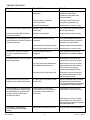
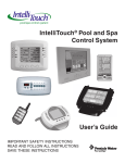
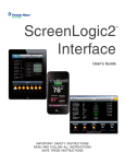
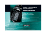
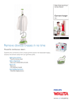
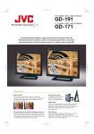
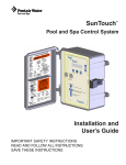
QuickTouch (QT4) Owner’s Manual
4-Function Hand-Held Wireless Remote Control
IMPORTANT SAFETY INSTRUCTIONS
READ AND FOLLOW ALL INSTRUCTIONS
SAVE THESE INSTRUCTIONS
Table of Contents
SECTION I.
APPLICATION ................................................................................................................................ 2
SECTION II.
KIT CONTENTS ............................................................................................................................. 2
SECTION III.
HAND-HELD REMOTE ................................................................................................................... 2
SECTION IV.
CONFIGURING BUTTONS ............................................................................................................. 3
SECTION V.
INSTALLATION ............................................................................................................................... 4
SECTION VI.
CUSTOMIZING THE COMMUNICATION LINK ............................................................................... 5
SECTION VII.
HAND-HELD REMOTE BATTERY REPLACEMENT ....................................................................... 5
TROUBLE-SHOOTING ................................................................................................................... 6
WARRANTY ................................................................................................................................... 7
WARNING
Risk of electrical shock or electrocution. It is required that the main power into the home be
switched off at the main circuit breaker box.
WARNING
Before installing this product, read and follow all warning notices and instructions which are included. Failure to
follow safety warnings and instructions can result in severe injury, death, or property damage.
Call (800) 831-7133 for additional free copies of these instructions.
Important Notice
Attention Installer.
This manual contains important information about the installation, operation and safe use of this
product. This information should be given to the owner/operator of this equipment.
Pentair Pool Products
1620 Hawkins Ave., Sanford, NC 27330 • (919) 774-4151
10951 West Los Angeles Ave., Moorpark, CA 93021 • (805) 523-2400
Rev. A 7-25-03
1
P/N 520209
SECTION I.
APPLICATION
Used in conjunction with the IntelliTouch Pool/Spa Control System.
Provides switching of four remote control circuits from a wireless Hand-held Remote.
It is typically used for activating the spa circulation, and for operating three auxiliary pieces of equipment
(such as lights, jet pump, air blower, waterfall, etc.).
Each of the four functions on the Hand-held Remote has an "ON" and an “OFF” button.
SECTION II.
1-qty.
1-qty.
4-qty.
4-qty.
KIT INCLUDES:
Hand-held Remote (P/N 520018)
Receiver (with 9½ ft. cable)
Plastic Anchors (for mounting Receiver to concrete or stucco walls)
Mounting screws (for mounting Receiver to a flat surface)
SECTION III. HAND-HELD REMOTE
The Hand-held Remote will control four circuits.
Although the Remote is capable of duplicating any four circuits, it has been preset at the factory to control the
following:
Spa Push-button activates the Spa circuit.
“A” Push-button activates Auxiliary 1 circuit.
“B” Push-button activates Auxiliary 2 circuit.
“C” Push-button activates Auxiliary 3 circuit.
If you would like to control circuits other than Spa, Aux1, Aux2 and Aux3, it is possible to make adjustments
through the Indoor Control Panel or MobileTouch.
USING THE HAND-HELD REMOTE
To activate a circuit, press and hold the appropriate "ON" button for at least a full second. To deactivate, press
and hold the OFF button in the same manner.
IMPORTANT
The Hand-held Remote may be used with wet hands, but should never be submersed in water, as this could damage the
unit. If accidental submersion occurs, dry unit out by removing battery cover and removing battery. Position unit so that
water can drain out. Reassemble when completely dry.
P/N 520209
2
Rev. A 7-25-03
SECTION IV. CONFIGURING BUTTONS
Configuring the Buttons of the 4-Function QuickTouch Wireless
Hand-held Remote to control your desired functions
Getting There
MENU
SETUP
ADVANCED
REMOTES
CONFIGURE QT WIRELESS
Hint: Before configuring the wireless remote,
assign names to the AUX circuits and / or
FEATURE circuits.
1
To configure the first
button on your wireless
remote, press the top
button at right. The arrow
indicates which button
your are working on.
Hint: The first button of the
wireless remote is labeled
SPA, so configure this
button for the spa mode,
as shown in the photo.
3 To configure the other
three buttons on your
wireless remote, repeat the
process using the next
three buttons at right.
2
Use the DOWN / UP
buttons to scroll through the
circuit names and find the
function you would like to
assign to the spa-side button
you are working on.
Rev. A 7-25-03
3
P/N 520209
SECTION V.
INSTALLATION
Receiver
The functional range of the wireless remote (from Hand-held Remote to Receiver)
is approximately 150 ft. line-of-sight.
The receiver should be mounted at a convenient location (on a flat vertical surface)
a minimum of 5 ft. above ground level to optimize the functional range of the
hand-held unit. See Figure 1 for major features.
CAUTION
The receiver should be mounted a minimum of 8 to 10 feet away from any air blower,
which may be part of the equipment set. The receiver will not operate properly if it is
close to a blower that is operating.
1. In order to mount the receiver, it will be necessary to remove the two retaining
screws located on the underside of the transceiver, and carefully slide the
transceiver case up and off of its back plate.
2. Temporarily position the back plate against its mounting surface so that the
receiver is oriented in an upright position (with antenna pointing upwards).
3. The circuit board will need to be temporarily removed. Slide the board up and
out of the back plate. Use a pencil to mark the four mounting points, and drill
3/16 in. dia. holes. Insert the four plastic anchors (provided).
4. Feed a UL approved four 22AWG conductor cable through one of the drain
holes at the bottom of the receiver enclosure. The preferred wire color
scheme is: red, yellow, green, and black. If the drain holes are not used, drill
a hole through the bottom of the back plate and seal using a fitting with a
few feet of conduit or some other sealant between the case and the cable.
5. Reposition the back plate over the mounting points and secure with the four
mounting screws (provided).
6. Strip the leads of the wires about ¼ in. and attach to controller screw terminals
of terminal plug as shown in Figure 2. Carefully slide the circuit board back
into the back plate and connect the terminal plug.
Figure 1.
7. Then slide the Receiver case back onto the back plate, and secure using the
two retaining screws.
CAUTION
Water damage may occur if the enclosure retaining screws are
not secured or a new hole is drilled for the cable and not sealed.
Do not seal drain holes.
4 15V
Load Center
Feed the four conductor cable from the receiver up the low
voltage raceway. Open the control panel and fold down to make
connections. To the left of the board are the COM PORT
connector(s). Strip the leads of the wires about ¼ in. and attach
to controller screw terminals of any COM PORT terminal plug
following the wiring diagram.
Close control panel, high voltage cover panel, and Load Center
door. Turn power to system back on.
P/N 520209
4
RED
3
+D
YELLOW
2
-D
GREEN
1 GND
BLACK
Figure 2.
Rev. A 7-25-03
SECTION VI. CUSTOMIZING THE COMMUNICATION LINK
The communication link between the Receiver and Hand-held Remote can be customized to prevent electrical
interference. To accomplish this, there is a 10-position configuration switch located on the Receiver circuit board,
and inside the Hand-held Remote. Units are shipped from the factory with all switches in the ON position.
If you wish to change this setting, use a paper clip or other blunt instrument and adjust both 10-position
configuration switches to matching settings. If the configuration switch setting at the Receiver does not match that
of the Hand-held Remote the communication link will not function.
COM LINK
Light
COMMAND
Light
Switch
Battery
Compartment
Receiver
Hand-held Remote
NOTE: All Program Switches are Factory set to “ON”.
If the IntelliTouch system has not been set to a new house address you should do so now. To set a new House
Address consult the main system instructions. The Load Center System Control lights will blink repeatedly when
a house address is being sent out.
If the system is sending a new house address, the COM LINK and COMMAND lights will blink together
repeatedly on the QT4 board.
If the system is sending an existing house address, the COM LINK and COMMAND lights will blink alternately.
While this is happening press any button of the Hand-held Remote. The COM LINK and COMMAND lights will
blink alternately. The main system may now be RESET. Wait for Auto Mode and the QT4 lights to stop blinking
before resuming normal operation.
SECTION VII. HAND-HELD REMOTE BATTERY REPLACEMENT
With normal use the battery should last for several years. In the event the battery must be replaced, slide the cover
from the bottom of the Hand-held Remote. Slide the battery from the retainer clip and discard in accordance with
local and/or state ordinances. Replace with 3V lithium battery number CR2032 or equivalent. Slide battery cover
onto remote and snap in place.
Rev. A 7-25-03
5
P/N 520209
TROUBLE-SHOOTING
Symptom
Possible Cause
Solution
POWER LED does not light.
Load Center does not
have power.
Insure power is being supplied
and that the Load Center
operates correctly without the
receiver installed.
Defective cable or connection
to the Load Center.
Verify the function of the board
using known good cable set.
Defective receiver board.
Contact factory or service center.
COM LINK LED does not light or blink.
Defective cable or connection to the
Load Center.
Verify the function of the board using
known good cable set.
In normal operation LED will blink at
least every 2 seconds.
Defective receiver board.
Contact factory or service center.
COMMAND LED does not light when
Hand-held Remote button(s) is pressed
- unit fails to operate.
Address switches are incorrectly
configured.
Verify that the address switches on
the Hand-held Remote and receiver
board are correct and match.
Hand-held Remote battery has failed.
Replace Hand-held Remote battery.
Defective Hand-held Remote or receiver.
Contact factory or service center.
Unit functions, but some circuits do
not work, or operate the incorrect
circuit.
Circuit selections incorrectly
configured.
Verify settings at Control Panel:
Unit fails to operate, or fails to operate
dependably at range.
Undue electrical noise.
Relocate the receiver away from
equipment such as blower motors.
Too many obstructions between the
Hand-held Remote and receiver.
Relocate the receiver in a location
that provides fewer obstructions to
the area the user commonly
operates the Hand-held Remote.
Receiver unit is too near the ground.
Relocate the receiver to maximize
the distance between the receiver
antenna and the ground.
Unit seems to turn on or off circuits
without the user / Hand-held Remote.
A nearby home is operating a similar
wireless unit.
Select an alternate address code for
the Hand-held Remote and receiver.
I.e. change the switches on both boards
to an alternate, but matching setting.
Unit dependably turns equipment ON,
but once equipment is running it does
not dependably turn equipment OFF,
or range is greatly reduced when
equipment is running.
Undue electrical noise is being
produced by one or more pieces of
equipment in close proximity to
the receiver.
Relocate the receiver away from
equipment such as blower motors.
MENU/SETUP/ADV/REM/QT REMOTE
Relocate the receiver in a location
that provides fewer obstructions to
the area the user commonly operates
the Hand-held Remote.
Unit operates, but has greatly
reduced range compared to prior
function.
P/N 520209
Hand-held Remote battery is failing.
6
Replace Hand-held Remote battery.
Rev. A 7-25-03
For questions, repairs, replacement parts, or information on possible Authorized Service
Centers within your vicinity call:
Pentair Pool Products ~ 800-831-7133
Or visit us on the Internet at www.pentairpool.com
Rev. A 7-25-03
7
P/N 520209
Pentair Pool Products
1620 Hawkins Ave., Sanford, NC 27330 • (919) 774-4151
10951 West Los Angeles Ave., Moorpark, CA 93021 • (805) 523-2400
P/N 520209
8
Rev. A 7-25-03