1
IntelliChlor™
Electronic Chlorine Generator
(Model IC20, IC40)
Installation and User’s Guide
Patents pending
IMPORTANT SAFETY INSTRUCTIONS
READ AND FOLLOW ALL INSTRUCTIONS
SAVE THESE INSTRUCTIONS
© 2006 Pentair Water Pool and Spa, Inc. All rights reserved
This document is subject to change without notice
1620 Hawkins Ave., Sanford, NC 27330 • (919) 566-8000
10951 West Los Angeles Ave., Moorpark, CA 93021 • (805) 553-5000
Trademarks and disclaimers
IntelliChlor, IntelliTouch, EasyTouch and the Pentair Water Pool and Spa logo are trademarks of Pentair Water Pool
and Spa, Inc. Other trademarks and trade names may be used in this document to refer to either the entities
claiming the marks and names or their products. Pentair Water Pool and Spa Inc. disclaims proprietary interest in
marks and names of others.
P/N 520589 Rev D - 04/28/2006
i
Contents
IntelliChlor Overview .................................................................................................................................... 1
Features ...................................................................................................................................................... 1
IntelliChlor models ....................................................................................................................................... 2
Electrolytic Cell Controller ............................................................................................................................ 3
IntelliChlor Power Center .............................................................................................................................. 3
System Diagram .......................................................................................................................................... 3
Loop Plumbing Diagram ............................................................................................................................... 4
IntelliChlor Plumbing Diagram ...................................................................................................................... 4
Section 1: IntelliChlor Control Panel ......................................................................................... 5
Salt Level Status LEDs ............................................................................................................................... 5
Status LEDs ................................................................................................................................................ 5
Sanitizer Output LED Indicators .................................................................................................................. 6
More and Less Output Buttons .................................................................................................................... 6
Self Cleaning (reverse) ................................................................................................................................ 6
Section 2: Operating IntelliChlor ............................................................................................... 7
Initial Startup Period .................................................................................................................................... 7
Operation ..................................................................................................................................................... 7
Startup Procedure (Super Chlorination) ........................................................................................................ 8
Apply power ................................................................................................................................................. 8
Operating in winter ....................................................................................................................................... 8
Recommendations ....................................................................................................................................... 8
General Cautions ......................................................................................................................................... 8
Section 3: User Maintenance ...................................................................................................... 9
Daily service. ............................................................................................................................................... 9
Weekly service. ........................................................................................................................................... 9
Monthly Service ........................................................................................................................................... 9
Cell Usage Hours Meter ............................................................................................................................. 10
Electrolytic Cell Cleaning ........................................................................................................................... 10
Winterizing ................................................................................................................................................. 11
Chemistry You Need to Know ..................................................................................................................... 11
Optimum Pool Water Conditions ................................................................................................................. 12
Chlorine Testing ......................................................................................................................................... 13
What Type of Salt to Use ........................................................................................................................... 13
How Much Salt to Use? ............................................................................................................................. 13
How to Add Salt to the Pool ....................................................................................................................... 14
Pool Water Preparation ............................................................................................................................... 16
Determining Pool Size (m3 of Water in Your Pool) ....................................................................................... 16
Determining Pool Size (Gallons of Water in Your Pool) ................................................................................ 16
IntelliChlor Pass-Through Cell .................................................................................................................... 16
Selecting Model Size ................................................................................................................................. 16
Section 4: Installation ............................................................................................................... 17
Kit Contents .............................................................................................................................................. 17
Required Tools ........................................................................................................................................... 17
Installing the Cell Assembly ...................................................................................................................... 18
Connecting the Cell Power Cable to the Power Center ............................................................................... 18
Connecting IntelliChlor to an IntelliTouch System ...................................................................................... 19
Connecting IntelliChlor to an EasyTouch System ....................................................................................... 21
Section 5: Troubleshooting ...................................................................................................... 22
Table 1: Troubleshooting IntelliChlor ............................................................................................................ 22
Table 2: Troubleshooting the Power Center ................................................................................................. 23
Electrical Specifications and 110 VAC and 220 VAC Wiring ....................................................................... 24
IntelliChlor Installation and User’s Guide
ii
IMPORTANT SAFETY PRECAUTIONS
SAVE THESE INSTRUCTIONS
Important Notice: Attention Installer: This manual contains important information
about the installation, operation and safe use of this product. This information should be given to the
owner and/or operator of this equipment. When installing and using this electrical equipment, basic
safety precautions should always be followed, including the following:
WARNING: IMPORTANT SAFETY INSTRUCTIONS PERTAINING TO A
RISK OF FIRE, ELECTRIC SHOCK, OR INJURY TO PERSONS READ. AND
FOLLOW ALL INSTRUCTIONS.
Before installing this product, read and follow all warning notices and instructions
which are included. Failure to follow safety warnings and instructions can result in
severe injury, death, or property damage. Call (800) 831-7133 for additional free
copies of these instructions.
WARNING: To reduce the risk of injury, do not permit children to use this product unless they
are closely supervised at all times.
WARNING: When mixing acid with water, ALWAYS ADD ACID TO WATER. NEVER ADD
WATER TO ACID.
WARNING: To reduce the risk of injury, service should only be attempted by a qualified Pool
Service Professional.
WARNING: Do not operate electrolytic cell without proper flow or water circulation. A build-up
of flammable gases will result in hazardous conditions.
CAUTION - This chlorinator is for use with permanently-installed pools and may also be used
with hot tubs and spas if so marked. Do not use with storable pools.
A permanently-installed pool is constructed in or on the ground or in a building such that it cannot be
readily disassembled for storage. A storable pool is constructed so that it is capable of being readily
disassembled for storage and reassembled to its original integrity.
CAUTION - When using IntelliChlor with an IntelliTouch system, it is recommended to wire the
IntelliChlor Power Center to the pump side of the relay located in the IntelliTouch Load Center. This
wiring method does not require a ground fault circuit-interrupter (GFCI) to protect the circuit. A
green colored terminal (or a wire connector marked “G”, “GR”, “Ground” or “Grounding”) is
provided within the terminal compartment in the Power Center transformer enclosure. To reduce
risk of electric shock, connect this terminal or connector to the grounding terminal of your electric
service or supply panel with a conductor equivalent in size to the circuit conductors supplying this
equipment. The power supply must be interconnected with pool pump motor power source. This
insures the IntelliChlor chlorinator and pool pump will switch on and off together.
IntelliChlor Installation and User’s Guide
iii
IMPORTANT SAFETY PRECAUTIONS
SAVE THESE INSTRUCTIONS
CAUTION - Use of chemicals other than those recommended may be hazardous. Follow the
Chemical Manufacturer’s Instructions.
CAUTION - To reduce the risk of electric shock, install IntelliChlor cell at least 5 feet from the
inside wall of the pool.
CAUTION - Install the IntelliChlor unit a minimum of two (2) feet from the heater outlet.
CAUTION - It is recommended to install a Pentair 2” CHECK VALVE (P/N 263042) between the
input side of the IntelliChlor cell and the main heater output pipe.
CAUTION - A solid copper, bonding conductor not smaller than No. 8 AWG (8.4 mm) should be
connected from the accessible wire connector on the unit to all metal
parts of the swimming pool, spa, or hot tub structure and to all electrical equipment, metal conduit,
and metal piping within 5 feet (1.5 m) of the inside walls of a swimming pool, spa, or hot tub, when
the unit is installed within 5 feet of the inside walls of the swimming pool, spa, or hot tub.
Canada - Industry Canada (IC) - This device complies with RSS210 of Industry Canada. (1999)
FCC Standard - 47 CFR Part 15, Subpart C (Section 15.247). This version is limited to chapter 1
to chapter 11 by specified firmware controlled in the U.S.A.
Federal Communications Commission (FCC) - This device complies with Part 15 of the FCC
Rules. Operation is subject to the following two conditions: (1) this device may not cause
interference, and (2) this device must accept any interference, including interference that may cause
undesired operation of the device.
Interference Statement - This equipment has been tested and found to comply with the limits for a
Class B digital device, pursuant to Part 15 of the FCC Rules. These limits are designed to provide
reasonable protection against harmful interference in a residential installation. This equipment
generates, uses and can radiate radio frequency energy and, if not installed and used in accordance
with the instructions, may cause harmful interference to radio communications. However, there is no
guarantee that interference will not occur in a particular installation. If this equipment does cause
harmful interference to radio or television reception, which can be determined by turning the
equipment off and on, the user is encouraged to try to correct the interference by one or more of the
following measures:
•
•
•
•
Reorient or relocate the receiving antenna.
Increase the separation between the equipment and receiver.
Connect the equipment into an outlet on a circuit different from that to which the receiver is
connected.
Consult the dealer or an experienced radio/TV technician for help.
Note: Modifications not expressly approved by the party responsible for FCC compliance could void
the user’s authority to operate the device.
IntelliChlor Installation and User’s Guide
iv
Declaration of Conformity
We declare, under our sole responsibility, that the product identified in this declaration, and to which
this declaration relates, are in conformity with the protection requirements of Council Directive 89/
336/EEC and standards IP33
•
•
•
Standard EN60335-1:2001, EN60529
Standard EN6100-3-2:2000, EN6100-3-3:1995 +A1:2001
Standard EN 55014-2: 1997 +A1:2001, EN 55014-1 2000 +A1, +A2 2002
Manufacturer:
Pentair Water Pool and Spa, Inc.
1620 Hawkins Ave, Sanford, NC 27330
10951 West Los Angeles Ave, Moorpark, CA 93021
Installation Steps Summary
The recommended IntelliChlor installation steps are:
1
Review Chemistry You Need to Know (page 11): Review this important information.
2
Review Optimum Pool Water Conditions (page 12): Review NSPI standards information.
3
Review Pool Water Preparation (page 16): Review this important information.
4
Installing the cell into the plumbing system - Connecting the cell to the Power Center
(page 17 - 21): Installing the cell into the pool plumbing system. Cabling the cell to the Power Center
and connecting IntelliChlor to an IntelliTouch or EasyTouch system.
5
Operating and Maintaining IntelliChlor (page 7 and 9): Operating and maintenance information
for IntelliChlor.
Technical Support
Contact Technical Support at:
Sanford, North Carolina (8 A.M. to 5 P.M.)
Phone: (800) 831-7133
Fax: (919) 566-8920
Moorpark, California (8 A.M. to 5 P.M.)
Phone: (800) 831-7133
Fax: (805) 530-0194
Web sites
visit www.pentairpool.com and www.staritepool.com
IntelliChlor Installation and User’s Guide
1
IntelliChlor Overview
The IntelliChlor™ salt chlorinator uses a process known as electrolysis to produce Sodium Hypochlorite (liquid
chlorine) from a low concentration of salt added to the pool water. Hypochlorite kills bacteria, oxidizes organic
material, and kills algae, then reverts back to salt. IntelliChlor then reuses the salt and the process starts over
again. The IntelliChlor system is comprised of the Power Center and Electrolytic Cell.
Features
•
Superior design combines cell and control panel as one assembly.
•
Cell blades are made from a titanium metal base and coated with precious metal Ruthenium oxide.
Cell blades are capable of lasting in excess of 10,000 hours.
•
•
•
•
•
•
•
•
•
•
•
•
The cell assembly can be installed horizontally or vertically.
Separate Power Center mounts to wall at equipment pad, for easy AC wiring.
Easily serviced.
Electronics run cool for long, reliable life.
Cell hours meter reports current usage to determine how many hours remain.
IC40 model produces up to 1.40 lbs. of chlorine per day. The IC20 model produces .70 lbs per day.
Salt level bar graph shows the amount of salt in pool.
Red and green LED indicators show system status for power, water flow, and cell status.
MORE and LESS output buttons control how much chlorine is produced.
BOOST cycle sets the unit to maximum chlorine output for 24 hours.
Cell lifetime is tracked with at-a-glance green LED indicators.
•
UL listed to UL1081 standards for swimming pool chlorinators.
IntelliChlor models
The IntelliChlor salt chlorinator system models are:
•
PC 100 (P/N 520556): Power Center Kit.
•
IC 20 Cell (P/N 520554): Designed for pools up to 20,000 U.S. gallons (75 liters), this cell will
produce approximately 0.70 pounds of chlorine per 24 hour period. This cell uses two terminal blades
and five bi-polar blades making this system more cost competitive.
•
IC 40 Cell (P/N 520555): Designed for pools up to 40,000 U.S. gallons (151 liters), the cell will
produce approximately 1.40 pounds of chlorine per 24 hour period. This cell uses three terminal
blades and ten bi-polar blades, five on each side of the center terminal blade. This will supply more
than enough chlorine for almost any residential and many smaller commercial pools.
•
IntelliChlor pass-through cell (P/N 520588): For new pool start-up.
IntelliChlor Installation and User’s Guide
2
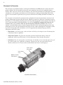
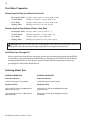
Electrolytic Cell Controller
The electrolytic cell controller includes a control panel with buttons and LED indicators to fully control and
produce chlorine. The cell controller measures the water temperature and salt level to optimally produce
chlorine. If the salt level is too low (red on salt display), the cell is turned off until salt is added to the pool. The
controller has a self-cleaning cycle which reverses the cell polarity, reducing calcium buildup. This feature
turns the cell on and off at regular intervals to prevent calcium and scale buildup and further maximizes cell
life.
The electrolytic cell contains the control electronics and bipolar electrodes that perform the electrolysis and
produce chlorine when energized with DC current. Chlorine is generated as pool water containing salt passes
through the cell. The chlorine production can be varied by either adjusting the sanitizer output level on the cell
or by varying the number of hours IntelliChlor is on each day. IntelliChlor automatically cleans the Cell
electrodes once every few hours. This does not interrupt the production of Chlorine. The cell also
contains a mechanical flow sensor to ensure the proper amount of water is passing through the cell to allow
chlorination to occur. The cell automatically measures the water salinity and temperature and displays on the
top of the cell using lights. The cell includes a 15 ft. UL approved four conductor 16 gauge cable for
connection to the Power Center.
•
Flow Sensor: A cell flow sensor assures that there will always be adequate water flow through the
cell no matter how it is plumbed.
•
Temperature Sensor: To protect the unit from operation and potential damage, when the
temperature of the water falls below 52° F, the temperature sensor switches the unit off.
•
Salt Sensor: Two salt sensor probes extend into the cell chamber and are activated upon start up of
the system and/or every eight hours of running. Upon start-up, the salt sensor flashes for two
minutes to indicate it is in analysis mode, then determines the salt level and displays it.
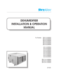
Control Panel
status LEDs
Clear sliding
cover
MORE and LESS
output buttons
IntelliChlor Cell Assembly
IntelliChlor Installation and User’s Guide
3
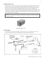
IntelliChlor Power Center
The Power Center converts AC electrical current to a low voltage DC current which is required by the cell to
perform the electrolysis. The power supply is connected with the pool circulation pump electrical source so
that the electrolytic cell only operates when the pool pump is on. The enclosure can be mounted vertically on
the wall up to 15 feet away from the cell controller. The Power Center contains the transformer, fuse,
connector to the cell and the 110 VAC and 220 VAC wiring configuration with the 36 VDC output cable to the
cell controller. A fuse holder is mounted on the bottom of this enclosure for additional protection. There are no
other controls or lights on the unit. For more information about the Power Center, see the “IntelliChlor Power
Center Installation Guide,” (P/N 520590).
IMPORTANT: Before plugging or unplugging the IntelliChlor cell to the Power Center, first switch off
the AC power to the Power Center, either by switching off the filter pump or setting the associated
circuit breaker to OFF.
Power Center (Model PC 100)
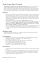
System Diagram
The following diagram shows the IntelliChlor system functionality. It is recommended to install a two inch
check valve between the input side of the IntelliChlor cell and the main heater output pipe.
Pool pump and
Power Center MUST
be wired to switch
on and switch off
together
Power Center
Pentair two inch Check
Valve (recommended)
(P/N 263042)
IntelliChlor Installation and User’s Guide
4
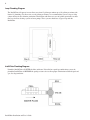
Loop Plumbing Diagram
The IntelliChlor will operate in water flow rates from 15 gallons per minute up to 110 gallons per minute (the
limit of 2” plumbing). For flow rates over 80 gallons per minute, it is recommend that you use a bypass loop
(shown below) for best chlorine production. Installations with flow rates over 80 gallons per minute are those
that have in-floor cleaning systems or boost pumps. These systems should use a bypass loop with the
IntelliChlor.
IntelliChlor Plumbing Diagram
Plumb the IntelliChlor cell AFTER the filter and heater. If installed on a pool/spa combination system, the
plumb the IntelliChlor cell BEFORE the pool/spa return valve to allow proper chlorination of both the pool and
spa. See diagram below.
IntelliChlor Installation and User’s Guide
5
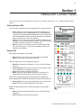
Section 1
IntelliChlor Control Panel
This section describes the IntelliChlor control panel status LEDs and the More, Less and Boost/On/Off control
buttons.
Salt Level Status LEDs
The salt level is checked daily and is displayed on this section of the unit.
•
•
•
Green: Good salt. The water salt level is above 2900 ppm, the
cell will produce chlorine. Flash green: Salt is above 4200 ppm.
Chlorine is being produced but the pool water may be corrosive to
other pool equipment. Water needs to be drained and refilled one
foot at a time until the salt level is lowered.
Yellow: Low salt. The water salt level is between 2500 ppm and
2900 ppm, salt should be added to the pool. The cell will continue
to produce chlorine, but will be at a reduced level.
Red: Very low salt. The water salt level has fallen below 2500
parts per million (ppm). The cell will not produce chlorine until
additional salt is added.
Status LEDs
Pwr: Shows the condition of the system:
•
•
Red: An error is occurring in the system. Service is needed.
Green: The system is operational and ready.
Cell: This light is on if the cell is producing chlorine.
•
•
•
•
Red: Water temperature is below 52° F, cell is shut off to extend
warranty.
Green (flashing): Cell is bad, may have calcium buildup, time to
clean, although it is still producing chlorine.
Green: Cell is good and producing chlorine
Blank: Cell is off and not producing chlorine. It may be in an
off-period of the sanitizing cycle and will return on shortly.
Life: The cell is designed to operate for approximately 10,000 hours
before replacement is needed or approximately five years of average use.
•
•
Green (flash): The cell is over 10,000 hours of life, replace soon.
Green: The cell is under 10,000 hours of life, good.
Flow: This light indicates water is flowing through the cell to produce
chlorine.
•
•
Conforms to
UL STD 1081
US
3077230
Red: Insufficient water flow through the cell, no chlorine will be
produced.
Green: Sufficient water to produce chlorine.
IntelliChlor Installation and User’s Guide
6
Operator Control Panel (continued)
Sanitizer Output LED Indicators
The five LED indicators display as a bar graph to show in 20% increments, the amount of time the chlorine is
produced per hour. In BOOST mode, these LEDs scroll in a pattern.
Note: If no LEDs are lit, the output is set to 0% and is not producing chlorine.
•
•
•
•
•
•
0%
20%
40%
60%
80%
100%
No LEDs on indicate no chlorine produced - IntelliChlor is off
Produces chlorine 20% of the hour, 12 minutes on, 48 minutes off
Produces chlorine 40% of the hour, 24 minutes on, 36 minutes off
Produces chlorine 60% of the hour, 36 minutes on, 24 minutes off
Produces chlorine 80% of the hour, 48 minutes on, 12 minutes off
Produces chlorine 100% of the hour, 59 minutes on, 1 minute off
Note: If connected to an IntelliTouch/EasyTouch system, these lights may slowly flash when the output
is set to a value not exactly 20%, 40%, 60% 80% or 100%. Example: 21% output setting from the
IntelliTouch/EasyTouch will flash the 20% light.
More and Less Output Buttons
The More and Less buttons control the sanitizing cycle as displayed by the sanitizer output display bar graph.
Slide the panel cover up to access the More, Less and Boost On/Off buttons.
Note: When connected to an IntelliTouch system the Less and More buttons are disabled and
IntelliChlor Sanitizer Output is controlled from the IntelliTouch Indoor Control Panel.
More: Increases the time the cell produces chlorine, in 20% increments. Example: The Sanitizer Output display
is showing 20%. Pressing the More button will turn off the 20% light and turn on the 40% light. The unit will now
produce chlorine 40% of an hour.
Less: Decreases the time the cell produces chlorine, in 20% increments. Example: The Sanitizer Output
display is showing 40%. Pressing the Less button will turn off the 40% light and turn on the 20% light. The
unit will now produce chlorine 20% of the hour.
Boost On/Off: Press and hold both the More and Less buttons together to activate Boost mode. Boost mode
sets the sanitizer output to run 100% for 24 hours straight. If the time clock switches off the pump cycle, then
switches power back on the next day, Boost mode will continue until 24 hours has elapsed or Boost mode is
canceled by the user. The Sanitizer Output display will show a pattern LED display to indicate Boost mode. To
exit Boost mode, press and hold both the More and Less buttons.
Self Cleaning (reverse)
The unit has a self-cleaning feature that reduces scale buildup on the cell blades. The self-cleaning cycle tends
to reduce cell life, so less often is better, however, it is important to minimize the scale buildup on the blades.
The cycle can be every 2, 4, 6, 8, or 10 hours. It is factory set to two hours for the first 30 days of operation,
then automatically switches to four hours. To change the self-cleaning cycle, press and hold the Less button
for three seconds. The sanitizer output display will now correspond to the self-clean cycle. Pressing More or
Less button will change this setting.
Example: The self-clean cycle is set to four hours and needs to be two hours. Press and hold the Less button
for three seconds. The sanitizer output will blank, then light up the 40% LED light only, indicating four hours.
If no button is pressed for five seconds, the display will return to the sanitizer output display. Pressing the Less
button within five seconds will now light the 20% LED light, indicating it is now at two hour self-clean cycle.
Wait five seconds and this mode will end, returning to the sanitizer output display.
IntelliChlor Installation and User’s Guide
7
Section 2
Operating IntelliChlor
This section describes the start up procedure and operating instructions for IntelliChlor.
Initial Start up Period
For the first 30 days of cell operation, the self-cleaning cycle will be set to two hours. After 30 days has
elapsed, the unit will automatically set itself to four hour self-cleaning cycle. This feature will clean the cell
more often on a new pool installation, then go to a more standard self-cleaning cycle for longer cell life.
Operation
Use of an external Pool Pump Timer is not required. IntelliChlor is designed to supply a sufficient
amount of chlorine to sanitize pool water on a daily basis. If IntelliChlor is operated 24 hours a day at 100%,
more chlorine would be generated than would be needed by most pools (1-3 PPM). IntelliChlor has its own
internal timer which cycles the electrolytic cell on and off depending on what percent the Chlorine Production
is set. For instance, at 100% the cell works all the time. When set at 80%, the cell is allowed to rest 20% of
the time prolonging cell life. In order to fine tune IntelliChlor to any size pool just increase or decrease the
Chlorine Production from 20% to 100%. Refer to “More and Less Output Buttons,” on page 6.
Note: Check Chlorine Level on a regular basis and adjust IntelliChlor accordingly.
CAUTION: Before attempting to operate IntelliChlor refer to “Recommendations and General Cautions,” on
page 8, and “Pool Water Preparation,” on page 17. Also, do not adjust Chlorine production above 20% until it is
certain that salt has been dissolved in pool. Operating without salt will result in the unit turning off and lighting
the ADD SALT light on the salt display. No chlorine will be produced until salt is added to the pool.
If you use a Pool Pump Timer. The Association of Pool and Spa Professionals (APSP) recommends that all
water in a residential pool pass through the filtration system at least once every 12 hours (referred to as pool
water turnover). However, many factors have an effect on actual pump and filter system run times. Pool size,
source of water, direct sun light, indoor/outdoor, screened/unscreened, filtration system, cold or hot weather,
swimmer load, rain, organic debris, algae, etc., are all factors which contribute to either more or less pool pump
and filter system run times. Because of these differences, it is extremely difficult to set an initial run time
(starting point) for the pool pump and chlorinating system.
Try initially setting the pool pump timer to 12 hours. It will take a few days to achieve the correct amount of
pool pump operating time. When IntelliChlor is wired with a pool pump timer results will vary greatly from
one pool installation to the next, so this should be discussed with either the pool builder or your
pool professional. The key points are:
•
Operate the pool pump at least the minimum time needed for good filtration.
•
The pool pump timer can reduce energy consumption.
Note: Exception - For Cold Weather Operation: The unit turns off in water temperatures of 52° F and
below, and will not produce chlorine. This feature extends the life of the cell.
IntelliChlor Installation and User’s Guide
8
Startup Procedure (Super Chlorination)
Shocking (Super Chlorination) is recommended before pool startup. Start out with clean pool water
from the beginning. IntelliChlor will build up a sufficient level of chlorine for sanitation in several hours.
However, if pool water has a high demand from the start-up IntelliChlor will not be able to produce enough
chlorine to reach break-point chlorination. So, it is best to super chlorinate from an outside source at the time
of pool startup. Then, wait until the chlorine level has returned to 1 to 3 PPM before turning on IntelliChlor.
Apply power
•
•
•
•
Switch on the pool pump switch or pool pump timer. The IntelliChlor control panel green PWR power
LED light should be on. The salt display will scroll all three LEDs for two minutes, indicating that it
has not checked the salt level yet. After two minutes, the salt will be checked and its level will be
displayed with a solid LED. If the salinity is below 2400 ppm, the salt display will light the red ADD
SALT indicator, and the CELL light will go blank, indicating there is not enough salt in the pool for
chlorine to be produced.
Set the Sanitizer Output to 60% by pressing the MORE or LESS button (page 6).
After 24 hours, use a reliable test kit to test the pool water for free active chlorine. The ideal range to
maintain is 1-3 PPM. If the chlorine content of the pool water is too low, increase chlorine
production by pressing the MORE button. If the chlorine content of the water is too high,
decrease chlorine production by pressing the LESS button.
Due to a varying chlorine demand of pool water, it may take a few days to determine the correct pool
operating time and chlorine production percentage setting for your pool. Continue adjusting as
necessary, allowing 24 hours between adjustments until the chlorine content of the pool is stabilized at
1-3 PPM.
Operating in winter
The unit turns off in water temperatures of 52° F and below, and will not produce chlorine. This feature
extends the life of the cell. See “Winterizing,” page 11.
Recommendations
•
•
•
•
•
•
•
After new pool construction has been completed, before installing the IntelliChlor cell, install the
IntelliChlor pass-through cell (P/N 520588) to remove debris from the pipes.
Read and keep the manual in a safe place.
Increase Chlorine Production before party time and return to normal afterwards.
Increase Chlorine Production when temperature goes up.
Increase Chlorine Production when number of guests goes up.
Use Stabilizer (Cyanuric Acid) to Stabilize Chlorine in Pool.
Take Pool water sample to Pool Professional once per month.
General Cautions
•
•
•
•
Do not get fertilizer in your pool. Fertilizers contain nitrates, which cause a high chlorine demand on
pool water.
Never use dry acid to adjust pH in arid geographic areas with excessive evaporation and minimal
dilution of pool water with fresh water. A buildup of byproducts can damage the electrolytic cell.
Do not add any pool water balancing chemicals (including salt) unless IntelliChlor is switched off.
Do not let Chlorine Stabilizer drop below 50 PPM.
IntelliChlor Installation and User’s Guide
9
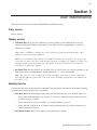
Section 3
User Maintenance
This section describes how to maintain the IntelliChlor chlorination system.
Daily service.
None is needed.
Weekly service.
1. Chlorine Test: Test pool water chlorine level with a reliable test kit. Maintain ideal range by
adjusting IntelliChlor chlorine production rate. See “More and Less Output Buttons,” on page 6.
•
Chlorine is 1-3 PPM.
Note: Above 3.0 PPM of chlorine may cause corrosion of pool metals and possibly cause
damage to associated pool equipment.
Note: It is recommended that chlorine test samples be taken from two places, one at the pool
return line, the other well away from the pool return line. Compare the samples. A higher level
should be found at the pool return line. The higher level at the pool return line indicates
IntelliChlor is producing chlorine.
2. pH Level Test: Test the pH level of your pool with a test kit. If necessary, adjust according to your
pool professional’s recommendations. APSP standard of 7.2 - 7.8 is recommended.
Note: Never use dry acid to adjust pH in arid geographic areas with excessive evaporation
and minimal dilution of pool water with fresh water. A buildup of byproducts can damage the
electrolytic cell.
Monthly Service
To ensure that the correct chemical balance is maintained in your pool, it is important to perform the following
recommended salt and pool water tests every month.
1. Salt Level Test: Check salt display lights on the unit and check that the green “GOOD” light is on.
•
If the yellow ADD Salt light is on (see page 5), add salt by following the procedures and charts
described on page 14 and 15.
•
If salt level does not rise after 24 hours, see “Troubleshooting,” page 22.
•
If the red LOW salt light is on, no chlorine will be produced until salt is added to the pool (see
charts beginning on page 14).
2. Pool Water Sample: Take water sample to local pool store for testing.
IntelliChlor Installation and User’s Guide
10
Monthly Service
(Continued)
3. Total Alkalinity Test: Test pool water for total alkalinity with a test kit. Adjust according to your pool
professional’s recommendations. 80-120 PPM APSP Standard.
4. Stabilizer (Cyanuric Acid): Test pool water stabilizer (cyanuric acid) level using a test kit or by
having a water sample tested by a pool professional. Maintain ideal range of 50-75 PPM. Follow your
pool professional’s recommendations.
5. Calcium Hardness: Test pool water for calcium hardness level using test kit or by having a water
sample tested by a pool professional. If necessary, adjust according to your pool professional’s
recommendations. APSP standard of 200-400 PPM is recommended.
6. Metals Test: It is recommended that the pool water be tested periodically for the presence of metals
such as copper, iron, and manganese. These metals should not be present in the pool water. If those
metals are present, contact the your pool professional.
Cell Usage Hours Meter
IntelliChlor provides a built-in cell “usage hours” meter that reports how many hours IntelliChlor has been
operating. The cell is designed to operate for approximately 10,000 hours before replacement is needed or
roughly five years of average use.
To access the system status mode:
1. Press and hold the MORE button for three seconds until the lights scroll across the unit.
2. One of the five Output LED indicators (20%, 40%, 60%, 80% and 100%) will be lit, indicating the
hours of usage. The Output LEDs are as follows:
•
•
•
•
•
2000 hours (20% LED on)
4000 hours (40% LED on)
6000 hours (60% LED on)
8000 hours (80% LED on)
10,000 hours (100% LED on)
Electrolytic Cell Cleaning
1. Automatic Cleaning. This unit has an automatic cell-cleaning feature (Cell Reversing) that removes
scale deposits from the electrolytic cell. Note Automatic Cleaning does not interrupt Chlorine
Production. “Scale” is a white crusty deposit that forms in excessively hard water or from pool
water that is out of balance and in a scaling condition. If the cell shows excessive scaling, you need
to perform an acid wash cleaning. Proceed to “Acid Wash Cleaning,” Step 2.
2. Acid Wash Cleaning. If the electrolytic cell has a tendency to scale, it is recommended that every
two months the cell be removed and inspected for scale formation and/or debris. Some filters allow
debris to pass through to the cell, possibly lodging between the plates in the cell. A small amount of
scale formation is normal. If by looking through the cell it is observed that there is excessive scale
formation between the plates or debris is present, the cell must be cleaned as follows:
a. Use a high-pressure jet of water from a garden hose. If the cell cannot be reasonably cleaned in this
manner, acid cleaning is necessary.
IntelliChlor Installation and User’s Guide
11
Electrolytic Cell Cleaning
(Continued)
b. To acid clean the cell: Disconnect the IntelliClor cell communication cable from the cell. Remove
the AC power from the Power Center, either by switching off the filter pump or setting the
associated circuit breaker to OFF.
c. Mix one quart of muriatic acid with one gallon of tap water in a plastic bucket.
WARNING
Working with muriatic acid can be dangerous.
When cleaning elements always wear rubber
gloves and eye protection. Always add acid to
water, do not add water to acid. Always work in a
well-ventilated area. Splashing or spilling acid
can cause severe personal injury and/or property
damage.
Note: The IntelliChlor acid cleaning kit (P/N
520670) provides a cap for the IntelliChlor
unit to allow acid to be poured into the
electrolytic cell plates for cleaning.
d. Place the cell vertically in a five gallon bucket. Pour the acid solution (as described above) into the
cell until the blades are just covered. Allow the acid solution to bubble, and to clean the blades. The
acid should only be contained in the cell and not around it. A foaming action will begin, which is
caused by scale (calcium carbonate) being dissolved from the plates. If rigorous foaming action does
not begin, the cell does not need to be cleaned (STOP THE CLEANING PROCESS - go on to
step “d”). Otherwise, allow the cell to remain in the solution until the foaming has
stopped. However, do not leave in acid for more than 1/2 hour. Excessive Acid Washing will
damage electrolytic cell.
e. Remove the cell from the bucket and place in an empty five gallon bucket. Rinse the cell thoroughly
with clean tap water and inspect. If deposits are still visible, immerse the cell again in the solution for
further cleaning. Additional acid may need to be added to the solution.
f. Rinse the cell again with clean tap water and inspect. If clean, replace the cell and resume normal
operation.
g. If the acid wash procedure is necessary, it is recommended that a sample of pool water be analyzed
by an authorized IntelliChlor service representative for excessive hardness and/or improper water
balance.
h. If no scale or debris deposits are observed in the cell after two bimonthly inspections, it is not
necessary to continue bimonthly inspections. However, due to possible changes in pool water
chemistry and filtering effectiveness, it is recommended that the cell be removed for inspection at
least twice a year.
i.
Insert the IntelliChlor cell cable plug into the Power Center connector, then restore AC power to the
Power Center.
Winterizing
Very little chlorine is needed in cold water. Below 52° Fahrenheit, chlorine production is stopped; the unit will
not produce chlorine. This low-temperature cut-off extends the life of the cell. If preventative measures are
not taken, freezing water may cause severe damage to the cell. Prevent freeze damage to the cell by running
the pool pump continuously or winterize the pool by draining water from pump, filter, and all intake and return
lines. Remove the cell, clean and store it.
Chemistry You Need to Know
1. Chlorine Stabilizer (cyanuric acid) is needed in outdoor pools to maintain proper levels of chlorine.
Most unstable chlorine is destroyed by the UV radiation from the sun within 2 hours. Chlorine
stabilizer should be maintained between 50 - 75 PPM. See Table 3, page 15.
IntelliChlor Installation and User’s Guide
12
Chemistry You Need to Know
(Continued)
2. Nitrates can cause extremely high chlorine demands and will deplete chlorine from your swimming
pool. In some cases Nitrates may even lower your chlorine levels to zero. The local pool professional
can test for Nitrates. Make sure Nitrates are not present in your pool.
3. Metals (some metals) can cause loss of chlorine. Also, metals can stain your pool. Have the local
pool professional check for metals and recommend methods of removal.
4. Chloramines should not be present in pool water. When organic materials combine with Free
Chlorine, Chloramines are formed. This ties up the Free Chlorine in your pool and does not allow the
chlorine in your pool to disinfect. Chloramines also cloud pool water and burn the eyes. (Super
Chlorinate (shock) to remove Chloramines at the initial startup of the pool).
5. Super Chlorination (Shocking) burns out the organic material that has combined with chlorine. This
frees the chlorine for sanitizing. This is accomplished by raising the chlorine level quickly and
dramatically. When the chlorine level is raised to 5 to 15 PPM the pool water is said to have been
Super Chlorinated (shocked). As pool water is continuously passed through the electrolytic cell, all
pool water inside the cell is being Super Chlorinated. When IntelliChlor is used on pools the pool
water sparkles and does not burn the eyes because of the absence of Chloramines.
Note: On initial start-up of a pool, it is best to Super Chlorinate from an outside source, i.e.,
use a shock treatment available at your local pool supplier.
6. pH produced by IntelliChlor is close to Neutral pH. However, other factors usually cause the pH of
the pool water to rise. Therefore, the pH in a pool chlorinated by IntelliChlor tends to stabilize at
approximately 7.8. This is within APSP standards. If the pool pH rises above 7.8, have a pool
professional test to see if other factors such as high Calcium Hardness or Total Alkalinity are the
cause and then balance accordingly.
7. Total Dissolved Solids (TDS): Adding salt to pool water will raise the TDS level. While this does
not adversely affect the pool water chemistry or clarity, the pool water professional testing for TDS
must be made aware salt has been added for the IntelliChlor system. The individual performing the
TDS test will then subtract the salinity level to arrive at the correct TDS level. See Table 3, page 15.
8. New Pool Water: A recently filled or newly-refinished pool may contain undesirable matter. This
undesirable matter could interfere with IntelliChlor’s ability to chlorinate properly. Make sure the
water is tested by a pool professional and properly balanced before turning on IntelliChlor.
Optimum Pool Water Conditions
In accordance with the Association of Pool and Spa Professionals (APSP) standards, it is recommended that
the following water balance conditions be maintained on an on going basis to protect the pool finish and
equipment and ensure the pleasing appearance of the water. IntelliChlor is warranted to operate properly only
if these conditions are met.
Free Chlorine: 2.0 - 3.0 PPM. Above 3.0 PPM may cause corrosion of pool metals
Combined Chlorine (Chloramines): None (Super Chlorinate to remove all Chloramines)
PH: 7.2 - 7.8 (USE MURIATIC ACID to lower pH and Soda Ash to raise pH.)
Chlorine Stabilizer (Cyanuric Acid):
50 - 75 PPM
Total Alkalinity:
80 - 120 PPM
Calcium Hardness:
150 - 400 PPM
Metals (Copper, Iron, Manganese):
None
Nitrates:
None
IntelliChlor Installation and User’s Guide
13
Chlorine Testing
It is recommended that chlorine test samples be taken from two places. Compare the samples. A higher level
should be found at the pool return line. The higher level at the pool return line indicates IntelliChlor is producing
chlorine.
Take chlorine test samples:
•
•
At the pool return line.
18 inches (457 mm) below the surface and well away from the pool return line.
What Type of Salt to Use
The purer the salt the better the life and performance of the electrolytic cell. Use a salt that is at least 99.8%
pure NaCl, sodium chloride. The preferred salt is an evaporated, granulated, food quality, non-iodized salt.
Consult your salt supplier.
•
•
•
•
Avoid using salt with anti-caking agents (sodium ferrocyanide, also known as YPS or yellow prussiate
of soda) that could cause some discoloration of fittings and surface finishes in pool.
Water conditioning salt pellets are compressed forms of evaporated salt and may be used, but will
take longer to dissolve.
Do not use calcium chloride as a source of salt. (Use sodium chloride only).
Do not use Rock salt (insoluble impurities mixed with the rock salt can shorten the life of the unit).
How Much Salt to Use?
Use the Table 1 chart (page 15) to determine how much salt will be needed. Most pools contain some salt,
depending on the water source and chemicals used for sanitizing. If IntelliChlor has not been wired and turned
on yet, a hand held meter calibrated for NaCl (salt) can be used to determine the existing salt concentration of
the water. If IntelliChlor is wired in (connected), use it to determine the salinity. Turn on the filter pump to
allow IntelliChlor to switch on. The salt display will flash the last known salt status light for two minutes while
it analyzes the water, then will turn solid. This solid light indicates the salt status of the pool.
•
•
•
3000 to 3500 ppm of salt is recommended for optimum water conditions.
Low salt concentration below 2400 ppm will cause the unit to turn off
High salt concentration above 6000 ppm may cause corrosion damage to pool fixtures.
Note: For more troubleshooting information about high salt levels, see “Troubleshooting,” on page 22.
IntelliChlor Installation and User’s Guide
14
How to Add Salt to the Pool
CAUTION: Do not operate IntelliChlor with newly poured pool plaster; salt damage can occur.
Wait at least 1 MONTH to allow new pool plaster to cure before operating IntelliChlor.
1. Switch on the pump to circulate the pool water.
2. Determine the amount of salt from the following charts.
3. Slowly pour in the salt around the outer perimeter of the pool for quick and even distribution. To
avoid clogging the filter or damaging power supply and pump, do not add salt through the
skimmer or surge tank.
4. Brush the pool bottom and allow water to circulate for 24 hours to dissolve completely.
5. After 24 hours, verify correct salt reading.
6. Switch on IntelliChlor and set to desired sanitizer output level (for example, 60%).
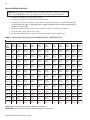
Table 1. Approximate Pounds (kg) of Salt Needed to Obtain 3,000 PPM in Pool
Pool Size (gallons)
Salt
Conc.
Before
Addition
38 m3
(10,000)
45 m3
(12,000)
53 m3
(14,000)
60 m3
(16,000)
68 m3
(18,000)
76 m3
(20,000)
8 m3
(22,000)
91 m3
(24,000)
98 m3
(26,000)
106 m3
(28,000)
113 m3
(30,000)
0 ppm
113 kg
(250
lbs)
136 kg
(300 lbs)
159 kg
(350 lbs)
181 kg
(400 lbs)
204 kg
(450 lbs)
227 kg
(500 lbs)
249 kg
(550 lbs)
272 kg
(600 lbs)
295 kg
(650 lbs)
318 kg
(700 lbs)
340 kg
(750 lbs)
250 ppm
104 kg
(230
lbs)
127 kg
(280 lb)
145 kg
(320 lbs)
168 kg
(370 lbs)
188 kg
(415 lbs)
209 kg
(460 lbs)
231 kg
(510 lbs)
249 kg
(550 lbs)
272 kg
(600 lbs)
293 kg
(645 lbs)
313 kg
(690 lbs)
500 ppm
95 kg
(210
lbs)
113 kg
(250 lbs)
134 kg
(295 lbs)
154 kg
(340 lbs)
172 kg
(380 lbs)
191 kg
(420 lbs)
209 kg
(460 lbs)
229 kg
(505 lbs)
247 kg
(545 lbs)
268 kg
(590 lbs)
286 kg
(630 lbs)
750 ppm
86 kg
(190
lbs)
104 kg
(230 lbs)
122 kg
(270 lbs)
136 kg
(300 lbs)
154 kg
(340 lbs)
172 kg(380
lbs)
191 kg
(420 lbs)
209 kg
(460 lbs)
225 kg
(495 lbs)
240 kg
(530 lbs)
259 kg
(570 lbs)
1000 ppm
75 kg
(165
lbs)
91 kg
(200 lbs)
104 kg
(230 lbs)
120 kg(265
lbs)
136 kg
(300 lbs)
150 kg
(330 lbs)
163 kg
(360 lbs)
181 kg
(400 lbs)
195 kg
(430 lbs)
209 kg
(460 lbs)
225 kg
(495 lbs)
1250 ppm
66 kg
(145
lbs)
79 kg
(175 lbs)
91 kg
(200 lbs)
104 kg
(230 lbs)
118 kg
(260 lbs)
132 kg
(290 lbs)
145 kg
(320 lbs)
159 kg
(350 lbs)
172 kg
(380 lbs)
186 kg
(410 lbs)
197 kg
(435 lbs)
1500 ppm
57 kg
(125
lbs)
68 kg
(150 lbs)
79 kg
(175 lbs)
91 kg
(200 lbs)
102 kg(225
lbs)
113 kg
(250 lbs)
125 kg
(275 lbs)
136 kg
(300 lbs)
147 kg
(325 lbs)
159 kg
(350 lbs)
170
(375 lbs)
1750 ppm
48 kg
(105
lbs)
59 kg
(130 lbs)
68 kg
(150 lbs)
77 kg
(170 lbs)
86 kg
(190 lbs)
95 kg
(210 lbs)
104 kg
(230 lbs)
113 kg
(250 lbs)
125 kg
(275 lbs)
134 kg
(295lbs)
143 kg
(315 lbs)
2000 ppm
39 kg
(85 lbs)
45 kg
(100 lbs)
54 kg
(120 lbs)
63 kg
(140 lbs)
68 kg
(150 lbs)
77 kg
(170 lbs)
86 kg
(190 lbs)
93 kg
(205 lbs)
100 kg
(220 lbs)
109 kg
(240 lbs)
116 kg
(255 lbs)
2250 ppm
27 kg
(60 lbs)
32 kg
(70 lbs)
39 kg
(85 lbs)
45 kg
(100 lbs)
50 kg
(110 lbs)
54 kg
(120 lbs)
59 kg
(130 lbs)
66 kg
(145 lbs)
73 kg
(160 lbs)
76 kg
(168 lbs)
82 kg
(180 lbs
2500 ppm
18 kg
(40 lbs)
23 kg
(50 lbs)
27 kg
(60 lbs)
29 kg
(65 lbs)
32
(70 lbs)
36 kg
(80 lbs)
41 kg
(90 lbs)
45 kg
(100 lbs)
48 kg
(105 lbs)
50 kg
(110 lbs)
54 kg
(120 lbs)
2700 ppm
9 kg
(20 lbs)
11 kg
(25 lbs)
14 kg
(30 lbs)
14 kg
(30 lbs)
18 kg
(40 lbs)
18 kg
(40 lbs)
20 kg
(45 lbs)
23 kg
(50 lbs)
23 kg
(50 lbs)
27 kg
(60 lbs)
27 kg
(60 lbs)
NOTE: Add salt as required to maintain 3000 ppm concentration
IMPORTANT: Add 1.25 lb (0.57 kg) of Stabilizer per 50 lb (22.7 kg) of Salt.
IntelliChlor Installation and User’s Guide
15
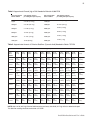
Table 2. Approximate Pounds (kg) of Salt Needed to Maintain 3,000 PPM
Salt concentration
before addition
Salt addition required
per 1000 gallon pool capacity
Salt concentration
before addition
0 ppm
25.6 lbs (11.6 kg)
1500 ppm
300 ppm
23.5 lbs (10.7 kg)
1800 ppm
500 ppm
21.4 lbs (9.7 kg)
2000 ppm
800 ppm
19.2 lbs (8.7 kg)
2300 ppm
1000 ppm
17.1 lbs (7.8 kg)
2500 ppm
1300 ppm
15 lbs (6.8 kg)
2800 ppm
Salt addition required
per 1000 gallon pool capacity
12.8 lbs (5.8 kg)
10.7 lbs (4.8 kg)
8.5 lbs (3.9 kg)
6.4 lbs (2.9 kg)
4.2 lbs (1.9 kg)
2.2 lbs (1 kg)
Table 3. Approximate Amount of Chlorine Stabilizer (Cyanuric Acid) Needed to Obtain 75 PPM
Pool Size (gallons)
Stabilizer
Level
Before
Addition
38 m3
(10,000)
45 m3
(12,000)
53 m3
(14,000)
60 m3
(16,000)
68 m3
(18,000)
76 m3
(20,000)
83 m3
(22,000)
91 m3
(24,000)
98 m3
(26,000)
106 m3
(28,000)
0.00 PPM
2.8 kg
(6.25 lbs)
3.4 kg
(7.50 lbs)
4 kg
(8.75 lbs)
4.5 kg
(10.0 lbs)
5 kg
(11.25lb)
5.7 kg
(12.5 lbs)
6.2 kg
(13.75 lbs)
6.8 kg
(15.0 lbs)
7.4 kg
(16.3 lbs)
7.9 kg
(17.5 lbs)
10 P P M
2.5 kg
(5.40 lbs)
2.9 kg
(6.50 lbs)
3.5 kg
(7.60 lbs)
3.9 kg
(8.60 lbs)
4.4 kg
(9.75 lbs)
5 kg
(10.8 lbs)
5.4 kg
(11.90 lbs)
5.8 kg
(12.9 lbs)
6.3 kg
(14.0 lbs)
6.9 kg
(15.2 lbs)
20 PPM
2 kg
(4.60 lbs)
2.5 kg
(5.50 lbs)
2.9 kg
(6.40 lbs)
3.3 kg
(7.30 lbs)
3.7 kg
(8.25 lbs)
4.1 kg
(9.20 lbs)
4.5 kg
(10.0 lbs)
4.9 kg
(10.9 lbs)
5.4 kg
(11.9 lbs)
5.8 kg
(12.8 lbs)
30 P P M
1.7 kg
(3.75 lbs)
2 kg
(4.50 lbs)
2.4 kg
(5.25 lbs)
2.7 kg
(6.00 lbs)
3 kg
(6.75 lbs)
3.4 kg
(7.50 lbs)
3.7 kg
(8.25 lbs)
4 kg
(9.00 lbs)
4.4 kg
(9.75 lbs)
4.8 kg
(10.5 lbs)
40 P P M
1.3 kg
(2.90 lbs)
1.6 kg
(3.50 lbs)
1.8 kg
(4.00 lbs)
2 kg
(4.60 lbs)
2.4 kg
(5.25 lbs)
2.6 kg
(5.80 lbs)
2.9 kg
(6.40 lbs)
3.1 kg
(6.90 lbs)
3.4 kg
(7.58 lbs)
3.7 kg
(8.20 lbs)
50 P P M
1 kg
(2.00 lbs)
1.1 kg
(2.50 lbs)
1.3 kg
(2.90 lbs)
1.5 kg
(3.30 lbs)
1.7 kg
(3.75 lbs)
1.9 kg
(4.10 lbs)
2 kg
(4.60 lbs)
2.2 kg
(4.90 lbs)
2.4 kg
(5.40 lbs)
2.6 kg
(5.80 lbs)
60 P P M
0.5 kg
(1.25 lbs)
0.7 kg
(1.50 lbs)
0.8 kg
(1.75 lbs)
1 kg
(2.00 lbs)
1 kg
(2.25 lbs)
1.1 kg
(2.50 lbs)
1.2 kg
(2.75 lbs)
1.4 kg
(3.00 lbs)
1.5 kg
(3.25 lbs)
1.6 kg
(3.50 lbs)
70 P P M
0.2 kg
(0.40 lbs)
0.2 kg
(0.50 lbs)
0.3 kg
(0.60 lbs)
0.3 kg
(0.66 lbs)
0.3 kg
(0.75 lbs)
0.4 kg
(0.80 lbs)
0.4 kg
(0.90 lbs)
0.4 kg
(1.00 lbs)
0.5 kg
(1.10 lbs)
0.5 kg
(1.20 lbs)
75 PPM
0 kg
(0.0 lbs)
0 kg
(0.0 lbs)
0 kg
(0.0 lbs)
0 kg
(0.0 lbs)
0 kg
(0.0 lbs)
0 kg
(0.0 lbs)
0 kg
(0.0 lbs)
0 kg
(0.0 lbs)
0 kg
(0.0 lbs)
0 kg
(0.0 lbs)
13 m3
(30,000)
8.5 kg
(18.75 lbs)
7.4 kg
(16.25 lbs)
6.2 kg
(13.75 lbs)
5.3 kg
(11.75 lbs)
4 kg
(8.75 lbs)
2.8 kg
(6.25 lbs)
1.7 kg
(3.75 lbs)
0.6 kg
(1.25 lbs)
0 kg
(0.0 lbs)
NOTE: Add 1.25 lb (0.57 kg) Chlorine Stabilizer to the pool every time 50 lb (22.7 kg) of Salt is added to the pool.
The Stabilizer reading should be maintained at 75 PPM.
IntelliChlor Installation and User’s Guide
16
Pool Water Preparation
Determining Pool Size (m3 of Water in Your Pool)
•
•
•
•
Rectangular Pools:
Circular Pools:
Oval Pools:
Sloping Sides:
Length x width (meters) x average depth x 1000
Diameter x diameter x average depth x 785
Length x width (meters) x average depth x 893
Multiply total m3 by 0.85 = m3 capacity.
Determining Pool Size (Gallons of Water in Your Pool)
•
•
•
•
Rectangular Pools:
Circular Pools:
Oval Pools:
Sloping Sides:
Length x width x average depth x 7.5
Diameter x diameter x average depth x 5.9
Length x width x average depth x 6.7
Multiply total gallons by 0.85 = gallon capacity
CAUTION: Never use dry acid to adjust pH in arid geographic areas with excessive evaporation and minimal
dilution of pool water with fresh water. A buildup of byproducts can damage the electrolytic cell.
IntelliChlor Pass-Through Cell
After new pool construction has been completed, in order to prevent debris from entering the IntelliChlor
cell assembly, it is recommended that the IntelliChlor pass-through cell (P/N 520588) be installed before
installing the IntelliChlor cell. After the pool system has flushed the debris from the pipes, remove the
pass-through cell and install the IntelliChlor cell.
Selecting Model Size
IntelliChlor Model IC20
IntelliChlor Model IC40
Chlorine Production
Chlorine Production
0.70 lb (317 gm) per 24-hour period.
1.40 lb (635 gm) per 24-hour period.
Residential Pools
Residential Pools
One unit per 57 m3 (up to 20,000 gallons)
pool (year round use)
One unit per 114 m3 (up to 40,000 gallons) pool
(year round use)
One unit per 66 m3 (up to 17,500 gallons)
pool (winterized).
One unit per 132 m3 (up to 35,000 gallons) pool
(winterized).
IntelliChlor Installation and User’s Guide
17
Section 4
Installation
This section describes how to install the IntelliChlor electrolytic cell assembly into the pool plumbing system.
Also, included are connection instructions for IntelliTouch and EasyTouch systems. Before installing, review
the IntelliChlor kit contents and required tools.
Note: For Power Center installation instructions, see the “IntelliChlor Power Center Installation
Guide” (P/N 520590).
Note: Salt is not provided. For details about the type of salt to use, see “What type of salt to use,”
on page 13.
Kit Contents
- One electrolytic cell
- Two cell union with two o-rings
- User’s Guide (this manual)
Required Tools
- Tape measure
- Phillips and flathead screwdriver
- Pliers
- Hacksaw
- An NSF® approved all purpose PVC/CPVC/ABS cleaner primer
- An NSF® approved all purpose PVC/CPVC/ABS cement
WARNING!
•
•
•
•
•
•
•
When using electrical products, basic precautions should always be followed,
including the following:
DANGER: RISK OF ELECTRIC SHOCK, WHICH CAN RESULT IN SERIOUS INJURY OR DEATH.
Before attempting installation of service, ensure that all power to the circuit supplying power to the
system is disconnected/turned off at the circuit breaker. It is recommended, but not mandatory that the
IntelliChlor Power Center be connected to a circuit protected by a ground fault circuit-interrupter (GFCI).
Grounding (earth bonding) is required. The unit should be installed by a qualified service person and
grounded.
Install to allow access to cell buttons and power center.
Read Safety Precautions and Important Instructions (page ii and iii). Before attempting any
electrical wiring, be sure to read and follow Safety Instructions. Wiring should only be
performed by a qualified professional.
Install the IntelliChlor unit a minimum of two (2) feet from the heater outlet.
Pipe couplings: Schedule 80, maximum pressure 150 psi at 70° F.
Note: Operate unit with minimum flow of 20 gpm. For high flow applications, use a bypass loop.
IntelliChlor Installation and User’s Guide
18
Installing the Cell Assembly
Install the IntelliChlor cell assembly no closer than three (3) feet from the heater outlet, if used. For more
information see plumbing diagrams on page 3 and 4.
Note: After new pool construction has been completed, in order to prevent debris from entering the
IntelliChlor cell assembly, it is recommended that the IntelliChlor pass-through cell (P/N 520588) be
installed before installing the IntelliChlor cell. After the pool system has flushed the debris from the
pipes, remove the pass-through cell and install the IntelliChlor cell.
Note: Pipe couplings: Schedule 80, maximum pressure 75 psi to 70° F
Coupling
Coupling
To install the cell:
1. Using PCV glue, mount the PVC couplings to the plumbing pipe. Allow the glue to dry.
2. Mount the cell to allow access to the control panel. Install the cell onto the couplings.
Ensure the O-rings are seated properly.
3. Switch on the pump and visually inspect for leaks around the couplings.
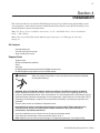
Connecting the Cell Power Cable to the Power Center
After the cell installation is completed, connect the power cable to the Power Center:
•
Align the four pins of the cell power cord connector with the socket on the bottom of the Power
Center and insert the connector. Turn the round socket nut until it locks the connector in place.
Connector socket nut.
To cell assembly
IntelliChlor Installation and User’s Guide
19
Connecting the Power Center to an IntelliTouch or EasyTouch System
To operate IntelliChlor with the IntelliTouch or EasyTouch system, connect a four wire cable from the
IntelliChlor Power Center to the IntelliTouch or EasyTouch load center. An alternate connection can be made
by splicing anywhere along the four wire connection that connects the IntelliTouch or EasyTouch indoor
control panel to the load center.
Note: For IntelliChlor operating instructions using the IntelliTouch system, see the “IntelliTouch User’s
Guide” (P/N 520102), or for the EasyTouch system, see the “EasyTouch User’s Guide” (P/N 520584).
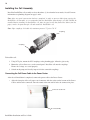
To connect IntelliChlor Power Center four wire cable to the IntelliTouch or EasyTouch load center:
1. Remove the cover screw securing the Power Center cover. Remove the cover.
2. Run a UL approved four conductor cable (22 AWG) from the IntelliChlor Power Center to the Load
Center. The preferred wire color scheme is red, yellow, green, and black.
3. Remove the cover screw securing the Power Center cover. Remove the cover.
4. Remove one of the knockouts from the underside of the Power Center.
5. Route the four conductor cable up through the lower hole.
6. Strip back the cable conductors ¼ in. Insert the wires into the screw terminals (provided in the kit).
Secure the wires with the screws. Make sure to match the color coding of the wires; Red = +15,
Yellow = +DT, Green = -DT, and GND = Black.
7. Plug the screw terminal onto the four pins located on the Power Center board.
8. Reinstall the cover and secure with the cover screw.
9. Proceed to “Connecting IntelliChlor to an IntelliTouch System,” on page 20 or “Connecting
IntelliChlor to an EasyTouch System,” on page 21.
Screw terminal
Conduit knockout
1
GND
B LK
2
- DT
GRN
3
+ DT
YEL
4
15V
R ED
Screw terminal
pin-outs
IntelliChlor Power Center (cover removed)
IntelliChlor Installation and User’s Guide
20
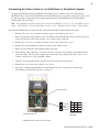
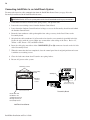
Connecting IntelliChlor to an IntelliTouch System
To connect the four wire cable communication from the IntelliChlor Power Center (see page 19) to the
Personality board located in the IntelliTouch load center:
WARNING Switch OFF main system power to the Load Center before making any connections.
1. Unlatch the load center enclosure door spring latches, and open the door.
2. Loosen the two retaining screws from the Outdoor Control Panel.
3. Lower down the Outdoor Control Panel on its hinges to access the Personality board located behind
the Outdoor Control Panel.
4. Route the four conductor cable up through the low voltage raceway in the Load Center to the
Personality board.
5. Strip back the cable conductors ¼ in. Insert the wires into the screw terminals (provided in the kit).
Secure the wires with the screws. Make sure to match the color coding of the wires; Red = +15,
Yellow = +DT, Green = -DT, and GND = Black.
6. Insert the cable plug onto either of the COM PORTS (J7 or J8) connectors located on the left side
of the Personality board.
7. When the connection has been completed, close the control panel into its original position and secure
it with the two retaining screws.
8. Close the load center front door. Fasten the two spring latches.
9. Restore AC power to the system.
Retaining screws
Personality
board
COM ports
Outdoor
Control
Panel
BLK
GRN
YEL
RED
Personality board
(Connector J7 or J8)
Personality Board
Route wire from
IntelliChlor into
conduit knockout up
through raceway to
Personality board
IntelliTouch Load Center
IntelliChlor Installation and User’s Guide
21
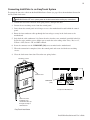
Connecting IntelliChlor to an EasyTouch System
To connect the four wire cable from the IntelliChlor Power Center (see page 19) to the motherboard located in
the EasyTouch load center:
WARNING Switch OFF main system power to the load center before making any connections.
1. Unlatch the load center enclosure door spring latches, and open the door.
2. Loosen the two retaining screws from the control panel.
3. Lower down the control panel on its hinges to access the motherboard located behind the control
panel.
4. Route the four conductor cable up through the low voltage raceway in the load center to the
motherboard.
5. Strip back the cable conductors ¼ in. Insert the wires into the screw terminals (provided in the kit).
Secure the wires with the screws. Make sure to match the color coding of the wires; Red = +15,
Yellow = +DT, Green = -DT, and GND = Black.
6. Insert the connector on the COM-PORT (J20) screw terminal on the motherboard.
7. When the connection is completed, close the control panel and secure it with the two retaining
screws.
8. Close the load center front door. Fasten the two spring latches.
Retaining screws
Control Panel
COM PORT
(J20)
Indoor Control Panel
IntelliChlor
IntelliFlo
RF Transceiver
EasyTouch Motherboard
Route wire from
IntelliChlor into
conduit knockout up
through raceway to
motherboard
EasyTouch Load Center
IntelliChlor Installation and User’s Guide
22
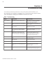
Section 5
Troubleshooting
Use the following troubleshooting information to resolve possible problems with the IntelliChlor system.
Note: Switch power off to unit before to attempting service or repair. Always remove AC power to Power
Center when plugging or unplugging the IntelliChlor cell into the Power Center.
Table 1: Troubleshooting
Problem
Possible Cause
Corrective Action
Low or no chlorine
Low stabilizer (cyanuric acid) level in pool
water
Add stabilizer to maintain 50 - 75 PPM per
pool professional's recommendations. See
Stabilizer Char t, Table 3, page 15.
Insufficient operating hours of the Chlorinator
unit
Increase the Chlorinator operating time per
day. See page 6.
CHLORINE PRODUCTION percentage set too
low or off at 0%
Increase chlorine production by pressing the
MORE button. See page 6.
Recent increases in weather temperature
without increasing the chlorine production of
your unit
Increase chlorine production by pressing the
MORE button. See page 6.
Temporar y loss of chlorine due to heavy
organic load-rain, leaves, fer tilizer or heavy
bather load, recent par ty, or pets using pool.
Set "Boost" mode and allow to run for 24
hours. Recheck, If still too low, superchlorinate with outside source. (Take pool
water sample to pool professional).
Low (less than 2500 ppm) salt level in pool
water.
Obser ve Salt Display lights. See "Salt Level
Status LEDs," page 5.
High nitrate level.
Contact Pool Professional.
Metals present in pool water.
Contact Pool Professional.
New pool water, or not shocked properly upon
star tup.
Super Chlorinate Pool. See "Star t-up
Installation," page 8.
Clogged or dir ty cell
Remove cell for inspection. Clean if necessar y.
See "Electrolytic Cell Cleaning," page 10.
IntelliChlor Installation and User’s Guide
23
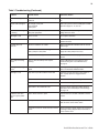
Table 1: Troubleshooting (Continued)
Problem
Possible Cause
Corrective Action
Red ADD salt light is
on.
Pool water needs salt. No chlorine is being
produced.
Add salt as described on pages 13, 14, and
15.
Yellow LOW salt light is
on.
Not enough salt in pool.
Heavy Rainfall.
Leak in pool.
Add salt to pool to achieve 3200 ppm to 3500
ppm. See page 13, 14, and 15.
Green GOOD salt light
is flashing
Too much salt in pool. May cause corrosion on
other pool equipment.
Dilute pool water by draining some water, then
filling with fresh water
PWR light is red
Call for service.
Unit requires attention.
Cell light is red
Water is below 52°F.
The water temperature must be above 52°F to
produce chlorine.
Cell light does not
come on.
Chlorine Production set to 00%.
Adjust CHLORINE PRODUCTION to desired
percentage.
Insufficient water flow. Cell is plugged with
debris, pump has lost prime.
Remove obstruction and/or clean cell. See
page 10. Prime pump if necessary.
Salt level below 2500 ppm.
Add salt as described on pages 13, 14,
and 15.
CELL light is flashing
green.
Cell has calcium build-up and requires
cleaning.
Refer to Maintenance Procedure for acid
wash/cleaning. See "User Maintenance,"
on page 9.
LIFE light is flashing
green.
Cell life has achieved 10,000 hours, life is
limited.
Prolong cell life by keeping salt at GREEN
level, and minimize BOOST modes.
Flow light is red
Pump fails to provide sufficient water flow.
Check for correct operation of the pump, i.e.,
loss of pump prime or clogged strainer
baskets.
Closed valves.
Check and correct all valve alignments.
Dir ty filter.
Follow filter cleaning procedures.
Obstruction in the Chlorinator cell.
Remove cell for inspection. Follow cleaning
procedures. See "Electrolytic Cell Cleaning,"
on page 10.
Fuse in Power Center is open.
Replace AC fuse, located at bottom of Power
Center.
No AC power to Power Center.
Verify time clock is providing 110 VAC or 220
VAC to Power Center when active.
Transformer leads not wired correctly in Power
Center.
Verify transformer leads wired to AC source by
referring to wiring diagram decal on inside of
Power Center cover.
IntelliChlor unit does
not have green power
light.
IntelliChlor Installation and User’s Guide
24
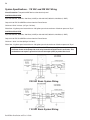
System Specifications - 110 VAC and 220 VAC Wiring
Circuit Protection: Two-pole 20 AMP device at the electrical panel.
IntelliChlor Model IC20
Input: 90-130 VAC, 50/60 Hz, 220 Watts (2 AMP) or 220-240 VAC, 50/60 Hz, 220 Watts (1 AMP).
Output: 22-39 VDC @ 6 AMPS maximum from the Power Center.
Chlorine: 0.70 lb. / 24 hour. (317 gm / 24 Hour).
Water flow: 15 gallons per minute minimum. 105 gallons per minute maximum. Maximum pressure: 75 psi
IntelliChlor Model IC40
Input: 90-130 VAC, 50/60 Hz, 220 Watts (2 AMP) or 220-240 VAC, 50/60 Hz, 220 Watts (1 AMP).
Output: 22-39 VDC @ 6 AMPS maximum from the Power Center.
Chlorine: 1.40 lb. / 24 Hour (635 gm / 24 Hour).
Water flow: 15 gallons per minute minimum. 105 gallons per minute maximum. Maximum pressure: 75 psi.
IMPORTANT: When using IntelliChlor with an IntelliTouch system, it is recommended to wire
the Power Center to the pump side of the relay located in the IntelliTouch Load Center. This
method does not require a ground fault circuit-interrupter (GFCI) to protect the circuit.
220 VAC Basic System Wiring
110 VAC Basic System Wiring
IntelliChlor Installation and User’s Guide
LIMITED WARRANTY
Pentair Water Pool and Spa, Inc. ("Pentair Water") manufactures its products with the highest standards of workmanship,
using the best materials available through state of the art process. Pentair Water warrants its products as follows:
Limited Warranty: Pentair Water warrants its products to be free from defects in material and/or workmanship for a
period of three (3) years or 8,000 hours (parts only) from the original date of installation.
Exceptions that could result in denial of a warranty claim:
1.
2.
3.
4.
5.
6.
7.
8.
Damage caused by careless handling, improper repackaging, or shipping.
Damage due to misapplication, misuse, abuse or failure to operate equipment as specified in the owners
manual.
Damage caused by failure to install products as specified in the owners manual.
Damage due to unauthorized product modifications or alterations, or failure to use Pentair Water original
replacement parts.
Damage caused by negligence, or failure to properly maintain products as specified in the owners manual.
Damage caused by failure to maintain water chemistry in conformity with the standards of the swimming pool
industry for any length of time.
Damage caused by water scaling, freezing or other conditions causing inadequate water circulation.
Accidental damage, fire, acts of God, or other circumstances outside the control of Pentair Water.
•
This warranty extends to the original retail owner only, beginning on the date of installation and is not
enforceable by any other party. Proof of purchase and/or date of installation will be required to execute a
warranty claim. Original owner agrees to repay all shipping charges to Pentair Water Pool and Spa Inc.
•
Warranties by others: Some products incorporate components manufactured by other manufacturers. Some of
these provide warranties in addition to the warranty provided herein. In all such cases a copy of that warranty
will be provided with the product. To the extent protection provided under any such third party warranty
exceeds the Limited Warranty provided herein, the Customer will have to look to that manufacturer for the
additional warranty protection.
Warranty Obligations of Pentair Water: Should a defect in workmanship and/or material in any item covered by this
warranty become evident during the term of the warranty, then upon the consumer following the procedures set forth
below, Pentair Water will, at its option, repair or replace such item or part at its own cost and expense.
Pentair Water is not, however, responsible under this warranty for any cost of shipping or transportation of the equipment
or parts thereof to or from the Technical Service Department. Also, Pentair Water is not liable for any loss of time,
inconvenience, incidental expenses such as telephone calls, labor or material charges incurred in connection with the
removal or replacement of the equipment, or any other incidental or consequential damages.
PLEASE NOTE: Some states do not allow the exclusion or limitation of incidental, or consequential damages, so the
above limitation or exclusion may not apply to you.
No Other Warranties: TO THE MAXIMUM EXTENT PERMITTED BY APPLICABLE LAW, PENTAIR WATER DISCLAIMS
ALL OTHER WARRANTIES, WHETHER EXPRESS OR IMPLIED, INCLUDING, BUT NOT LIMITED TO THE IMPLIED
WARRANTIES OF MERCHANTABILITY AND FITNESS FOR A PARTICULAR PURPOSE.
Procedure for Obtaining Performance: In order to obtain the benefits of this warranty, the consumer who made the
original retail purchase must contact the Pentair Water Technical Service Department upon discovery of the defect, but in
no event later than the expiration date of the warranty period provided in this warranty. Upon receipt of this
communication, Pentair Water will promptly notify the customer of the address to which the defective item may be
shipped. The customer shall then ship the item, freight prepaid, to the address indicated, together with a "RETURN
GOODS AUTHORIZATION" form obtained from Technical Service and a brief description of the problems encountered.
Unauthorized returns will not be accepted. Freight must be prepaid by customer.
Warranties or Representations by Others: No dealer or other person has any authority to make any warranties or
representations concerning Pentair Water or its products. Accordingly, Pentair Water is not responsible for any such
warranties or representations.
Other Rights: This warranty gives you specific legal rights and you may also have other rights, which vary from state to
state. This warranty supersedes all previous publications.
PENTAIR WATER POOL AND SPA, INC.
1620 Hawkins Ave. Sanford, NC 27330 - 10951 W. Los Angeles Ave. Moorpark, CA 93021 - Phone 800-831-7133 - Fax 800-284-4151
P/N 520589 - Rev D