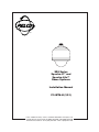
1
®
SD5 Series
Spectra II™ and
Spectra Lite™
Dome Systems
Installation Manual
C1487M-H (1/01)
Pelco • 3500 Pelco Way • Clovis, CA 93612-5699 USA • www.pelco.com
In North America and Canada: Tel (800) 289-9100 • FAX (800) 289-9150
International Customers: Tel +1(559) 292-1981 • FAX +1(559) 348-1120
2
Pelco Installation Manual C1487M-H (1/01)
CONTENTS
Section
Page
IMPORTANT SAFEGUARDS AND WARNINGS .................................................................................................................... 4
INSTALLATION .......................................................................................................................................................................5
HARD CEILING INSTALLATION .................................................................................................................................... 6
SUSPENDED CEILING INSTALLATION ....................................................................................................................... 8
PENDANT-MOUNT INSTALLATION ............................................................................................................................. 10
SURFACE-MOUNT INSTALLATION ............................................................................................................................. 12
TROUBLESHOOTING ........................................................................................................................................................... 14
APPENDIX ............................................................................................................................................................................. 15
SPECIFICATIONS ................................................................................................................................................................. 19
CERTIFICATIONS AND REGULATORY NOTICES ....................................................................................................... 23
WARRANTY AND RETURN INFORMATION ........................................................................................................................ 24
LIST OF ILLUSTRATIONS
Figure
1
Page
SD5 Series Dimension Drawing ............................................................................................................................ 20
LIST OF TABLES
Table
A
B
C
D
E
Page
Video Coaxial Cable Wiring Distances .................................................................................................................. 15
24 VAC Wiring Distances ....................................................................................................................................... 15
Switch Settings for SW1 ........................................................................................................................................ 15
Switch Settings for SW2 – P-Type Control ............................................................................................................ 16
Switch Settings for SW2 – D-Type Control ............................................................................................................ 16
Pelco Installation Manual C1487M-H (1/01)
3
IMPORTANT SAFEGUARDS AND WARNINGS
Prior to installation and use of this product, the following WARNINGS should be observed.
1. Installation and servicing should only be done by qualified service personnel and conform to all local codes.
2. Unless the unit is specifically marked as a NEMA Type 3, 3R, 3S, 4, 4X, 6, or 6P enclosure, it is designed for indoor use only and it
must not be installed where exposed to rain and moisture.
3. Only use replacement parts recommended by Pelco.
4. After replacement/repair of this unit’s electrical components, conduct a resistance measurement between line and exposed parts to
verify the exposed parts have not been connected to line circuitry.
5. The installation method and materials should be capable of supporting four times the weight of the enclosure, pan/tilt, camera and
lens combination.
The product and/or manual may bear the following marks:
This symbol indicates that dangerous voltage
constituting a risk of electric shock is present within
this unit.
CAUTION:
RISK OF ELECTRIC SHOCK.
DO NOT OPEN.
This symbol indicates that there are important
operating and maintenance instructions in the
literature accompanying this unit.
Please thoroughly familiarize yourself with the information in this manual prior to installation and operation.
MEASURES DE SECURITE IMPORTANTES
Avant d’installer ou d’utiliser ce produit, les mesures de sécurité suivantes sont à prendre:
1. Toute installation et réparation devraient être entreprises par un technicien qualifié et conformes au codes locaux.
2. A moins que cet equipement indique avoir un boitié agrée NEMA de type 3, 3R, 3S, 4, 4X, 6 ou 6P, il est uniquement conçu pour
utilisation intérieure et ne peut donc pas être en contact de pluie ou d’humidité.
3. Utiliser seulement les pièces de rechanges recommandées par Pelco.
4. Après toute installation ou réparation de la partie électrique de ce produit, une résistance entre le courant et la partie exposée devrait
être installée afin de vérifier que la partie électrique n’aie pas été en contact d’un court circuit.
5. L’installation entreprise et le matériel utilisé devraient supporter quatre fois le poids du boitié, de la tourelle, de la caméra, et de la
lentille.
Ce produit et/ou le manuel pourrait inclurent les symbols suivants:
Ce symbol indique qu’un voltage dangereux
pouvant provoquer un chock électrique est
présant dans cette unité.
Ce symbol indique qu’il y a des mesures
d’installation et d’entretient importantes
inclus dans le manuel de cet équipement.
CAUTION:
RISQUE DE CHOQUE ÉLECTRIQUE.
NE PAS OUVRIR.
Nous vous prions de bien vous familiarisez avec la manuel avant d’entreprendre toute installation.
4
Pelco Installation Manual C1487M-H (1/01)
INSTALLATION
The Spectra II™ dome and Spectra Lite™ dome shipping cartons contain three boxes. Inspect each box to make sure all parts are
present.
IN-CEILING MODELS
PENDANT MODELS
Back Box
1 Back box
1 Parts bag
1 Conduit fitting
1 Safety chain bracket
1 Lock nut
1 Compass tool
4 T-rail clip (clip, L-bracket, screw, lock washer and nut)
Dome Drive
1 Dome drive
Lower Dome
1 Acrylic lower dome with trim ring
Back Box
1 Back box
1 Tube of thread compound
Dome Drive
1 Dome drive
Lower Dome
1 Acrylic lower dome with trim ring
1 Parts bag (O-ring and lubricant, and tube of Loctite)
BACK BOX
BACK BOX
DOME DRIVE
DOME DRIVE
LOWER DOME
LOWER DOME
COMPASS TOOL
SAFETY BRACKET
T-RAIL CLIP
CONDUIT FITTING & LOCK NUT
THREAD LOCTITE®
COMPOUND 222MS
Pelco Installation Manual C1487M-H (1/01)
O-RING
LUBE
O-RING
5
HARD CEILING INSTALLATION
IN-CEILING MODELS
STEP 1 - PREPARE CEILING
a. Locate the center point of the mounting location. Drill a hole in
the ceiling using a 3/32-inch drill. Insert the compass tool into
the hole.
b. Draw a circle on the ceiling using the compass tool and a
pencil. Cut the circle out of the ceiling.
STEP 2 - INSTALL THE BACK BOX
ATTACH SAFETY CHAIN HERE
a. Attach the conduit fitting, lock nut, and safety chain bracket.
Install a safety chain/cable (not supplied) that will support up
to 16 pounds (7.3 kg).
b. Turn the thumb screw and open the hinged door to the back
box. Pull wiring into the back box through the conduit fitting.
Refer to Tables A and B in the Appendix for wiring distances.
CEILING TILE
c. Compress the spring clips on the back box and push it through
the hole, until the clips spring back. Tighten the screws until
you hear a clicking noise.
6
Pelco Installation Manual C1487M-H (1/01)
POWER
(24 VAC ONLY)
24 VAC
TRANFORMER
CONTROLLER
d. Attach the wiring to the circuit board inside the back box. When
finished, close the door to the back box and turn on the power.
The red LED will light.
COAXITRON
CONTROLLER
VIDEO IN
VIDEO OUT
TXTX+
2 WIRE
CONTROLLER
RXRX+
TXTX+
NOT USED
NOT USED
IMPORTANT: If the LED does not light, refer to the Troubleshooting section.
1
2
ALARM
3
INPUTS
4
5
6
7
GROUND
SPECTRA II ONLY
NOTE: Aux 1 - Maximum 2A at low voltage (<40V)
Aux 2 - Maximum 150 vA at 32 VDC
SWITCHES
+5 VDC (WIRING EXAMPLE)
+5 to +24 VDC
CONTROL
(RS-422)
(NO) RELAY
(NC) (AUX 1)
LOGIC GATE
(WIRING EXAMPLE)
GROUND
AUX 2
HEATER/FAN
(NOT USED)
AUX 2
EXTERNAL RELAY
(WIRING EXAMPLE)
STEP 3 - INSTALL DOME DRIVE
SW1
SW2
ON
1
2
3
4
5
6
7
8
LABEL
SW1
ON
SW2
1
2
3
4
5
6
7
GREEN
TAB
8
RED
TAB
LABEL
SW2
RS-422 TERMINATION SWITCH
00303
a. Set the DIP switches for SW1 and SW2 on the bottom of the
dome drive for the appropriate receiver address. Refer to the
labels on the dome drive or Tables C through E in the Appendix in the back of this manual.
c. Line up the green and red tabs with the green and red labels.
Push in on the tabs. Insert the side with the green tab, then the
side with red tab. Continue pushing on the ends of the tabs
until both sides click into place.
b. Daisy Chain Operation Only – When connecting more than
one Spectra dome system to a single controller, terminate the
last unit in the chain (farthest from the controller). To terminate
the dome drive set the RS-422 termination switch to the left.
STEP 4 - INSTALL LOWER DOME
a. Snap the clip, on the end of the trim ring leash, into the hole on the
lip of the back box.
b. Line up the snaps on the trim ring with the mounting screws on the
back box. Snap the trim ring into the plastic snap washers on the
mounting screws.
TO USE YOUR DOME, REFER TO THE
OPERATION AND PROGRAMMING MANUAL.
Pelco Installation Manual C1487M-H (1/01)
7
SUSPENDED CEILING INSTALLATION
IN-CEILING MODELS
STEP 1 - PREPARE CEILING TILE
NOTE: The ceiling tile cannot be thinner than 0.50-inch (1.27 cm) or thicker than 1.75-inches (4.45 cm).
a. Remove the ceiling tile from the ceiling. Insert the compass tool (supplied) into the center of the tile. (If necessary use a 3/32-inch bit
to drill a hole.)
b. Draw a circle on the tile using the compass tool and a pencil. Cut the circle out of the ceiling tile.
STEP 2 - INSTALL THE BACK BOX
ATTACH SAFETY CHAIN HERE
a. Attach the conduit fitting, lock nut, and safety chain bracket.
Install a safety chain/cable (not supplied) that will support up
to 16 pounds (7.3 kg).
b. Turn the thumb screw and open the hinged door to the back
box. Pull wiring into the back box through the conduit fitting.
Refer to Tables A and B in the Appendix for wiring distances.
CEILING TILE
T-RAIL CLIP
FOR
CEILING TILE
c. Compress the spring clips on the back box and push it through
the hole, until the clips spring back. Tighten the screws until
you hear a clicking noise.
8
T-RAIL CLIP
FOR
CEILING TILE
d. Install the ceiling tile with the back box. Attach a T-rail clip on
each side of the ceiling tile. Fasten the L-bracket to the clip
with the supplied screw and washers.
Pelco Installation Manual C1487M-H (1/01)
e. Attach the wiring to the circuit board inside the back box. When
finished, close the door to the back box and turn on the power.
The red LED will light.
CONTROLLER
COAXITRON
CONTROLLER
IMPORTANT: If the LED does not light, refer to the Troubleshooting section.
NOTE:
POWER
(24 VAC ONLY)
24 VAC
TRANFORMER
VIDEO IN
VIDEO OUT
TXTX+
2 WIRE
CONTROLLER
NOT USED
NOT USED
Aux 1 - Maximum 2A at low voltage (<40V)
Aux 2 - Maximum 150 vA at 32 VDC
SPECTRA II ONLY
SWITCHES
+5 VDC (WIRING EXAMPLE)
+5 to +24 VDC
LOGIC GATE
(WIRING EXAMPLE)
CONTROL
(RS-422)
1
2
ALARM
3
INPUTS
4
5
6
7
GROUND
(NO) RELAY
(NC) (AUX 1)
GROUND
AUX 2
EXTERNAL RELAY
(WIRING EXAMPLE)
RXRX+
TXTX+
AUX 2
HEATER/FAN
(NOT USED)
STEP 3 - INSTALL DOME DRIVE
SW1
SW2
ON
1
2
3
4
5
6
7
8
LABEL
SW1
ON
SW2
1
2
3
4
5
6
7
GREEN
TAB
8
RED
TAB
LABEL
SW2
RS-422 TERMINATION SWITCH
00303
a. Set the DIP switches for SW1 and SW2 on the bottom of the
dome drive for the appropriate receiver address. Refer to the
labels on the dome drive or Tables C through E in the Appendix in the back of this manual.
c. Line up the green and red tabs with the green and red labels.
Push in on the tabs. Insert the side with the green tab, then the
side with red tab. Continue pushing on the ends of the tabs
until both sides click into place.
b. Daisy Chain Operation Only – When connecting more than
one Spectra dome system to a single controller, terminate the
last unit in the chain (farthest from the controller). To terminate
the dome drive set the RS-422 termination switch to the left.
STEP 4 - INSTALL LOWER DOME
a. Snap the clip, on the end of the trim ring leash, into the hole on the
lip of the back box.
b. Line up the snaps on the trim ring with the mounting screws on the
back box. Snap the trim ring into the plastic snap washers on the
mounting screws.
TO USE YOUR DOME, REFER TO THE
OPERATION AND PROGRAMMING MANUAL.
Pelco Installation Manual C1487M-H (1/01)
9
PENDANT-MOUNT INSTALLATION
PENDANT MODELS
STEP 1 - MOUNT AND INSTALL THE BACK BOX
NOTE: If installing outdoors make sure the installation is properly sealed to keep moisture out.
a. Install the mount for the pendant dome. Refer to the instructions supplied with the mount. Bring the wiring for the dome
through the mount. Refer to Tables A and B in the Appendix for
wiring distances.
b. Turn the thumbscrew and open the hinged door located inside
the back box.
c. Pull wiring from the mount into the back box.
d. Screw the back box into the mount. If outdoors, apply thread
compound (provided) to the threads on the back box.
POWER
(24 VAC ONLY)
24 VAC
TRANFORMER
STEP 2 - WIRE CIRCUIT BOARD
CONTROLLER
Attach the wiring to the interconnect circuit board inside the back
box. Close the door to the back box. Turn on power to the back
box. The red LED will light.
COAXITRON
CONTROLLER
VIDEO IN
VIDEO OUT
TXTX+
2 WIRE
CONTROLLER
NOT USED
NOT USED
IMPORTANT: If the LED does not light, refer to the Troubleshooting section.
NOTE: Aux 1 - Maximum 2A at low voltage (<40V)
Aux 2 - Maximum 150 vA at 32 VDC
SPECTRA II ONLY
SWITCHES
+5 VDC (WIRING EXAMPLE)
+5 to +24 VDC
LOGIC GATE
(WIRING EXAMPLE)
10
CONTROL
(RS-422)
1
2
ALARM
3
INPUTS
4
5
6
7
GROUND
(NO) RELAY
(NC) (AUX 1)
GROUND
AUX 2
EXTERNAL RELAY
(WIRING EXAMPLE)
RXRX+
TXTX+
AUX 2
HEATER/FAN
(NOT USED)
Pelco Installation Manual C1487M-H (1/01)
STEP 3 - INSTALL DOME DRIVE
SW1
SW2
ON
1
2
3
4
5
6
7
8
LABEL
SW1
ON
SW2
1
2
3
4
5
6
7
GREEN
TAB
8
RED
TAB
LABEL
SW2
RS-422 TERMINATION SWITCH
00303
a. Set the DIP switches for SW1 and SW2 on the bottom of the
dome drive for the appropriate receiver address. Refer to the
labels on the dome drive or tables C through E in the Appendix
in the back of this manual.
b. Daisy Chain Operation Only – When connecting more than
one Spectra dome system to a single controller, terminate the
last unit in the chain (farthest from the controller). To terminate
the dome drive set the RS-422 termination switch to the left.
c. Line up the green and red tabs with the green and red labels.
Push in on the tabs. Insert the side with the green tab, then the
side with red tab. Continue pushing on the ends of the tabs
until both sides click into place.
STEP 4 - INSTALL LOWER DOME
LEASH
ATTACH
LEASH TO
NEAREST
RETAINER
SCREW
a. Lightly apply O-ring lubricant to the O-ring. Install the O-ring in
the groove on the trim ring of the lower dome.
MOUNTING
SCREW HOLES
FRONT & BACK
b. Attach the back box trim leash to the lower dome. Use retainer
screw (nearest to a mounting screw) inside lower dome.
NOTE: If you are installing an outdoor model,
plug the two-pin heater
connection in the lower
dome into the mating
connector in the back
box.
c. Remove the two lower dome, mounting screws. Apply a drop
of Loctite 222MS (supplied) to each screw.
d. Push the lower dome inside the back box, line up the mounting
screw holes, and install the two mounting screws.
TO USE YOUR DOME, REFER TO THE OPERATION AND PROGRAMMING MANUAL.
Pelco Installation Manual C1487M-H (1/01)
11
SURFACE-MOUNT INSTALLATION
PENDANT MODELS
STEP 1 - REMOVE THE TOP PORTION OF THE BACK BOX
a. Turn the thumbscrew and open the
hinged door located inside the back box.
b. Unscrew the three Phillips screws located underneath the hinged door.
c. Remove the top portion of the back box.
STEP 2 - PREPARE SURFACE AND INSTALL THE BACK BOX
NOTE: If installing outdoors
apply a sealant between the
back box and the mounting
surface
a. Determine the mounting location. Use the base of the back box as a template. Mark the fastener and center hole positions onto the
mounting surface.
b. Drill a hole in the center of the mounting surface. Pull wiring through the opening. Refer to Tables A and B in the Appendix for wiring
distances. Prepare the holes for the fasteners. Position the back box over the mounting holes and pull wiring into the back box.
Secure the back box to the mounting surface using the appropriate hardware for your installation.
POWER
(24 VAC ONLY)
24 VAC
TRANFORMER
STEP 3 - WIRE CIRCUIT BOARD
Attach the wiring to the interconnect circuit board inside the back
box. Close the door to the back box. Turn on power to the back
box. The red LED will light.
IMPORTANT: If the LED does not light, refer to the Troubleshooting section.
CONTROLLER
COAXITRON
CONTROLLER
VIDEO IN
VIDEO OUT
TXTX+
2 WIRE
CONTROLLER
NOT USED
NOT USED
SPECTRA II ONLY
NOTE: Aux 1 - Maximum 2A at low voltage (<40V)
Aux 2 - Maximum 150 vA at 32 VDC
SWITCHES
+5 VDC (WIRING EXAMPLE)
+5 to +24 VDC
LOGIC GATE
(WIRING EXAMPLE)
12
CONTROL
(RS-422)
1
2
ALARM
3
INPUTS
4
5
6
7
GROUND
(NO) RELAY
(NC) (AUX 1)
GROUND
AUX 2
EXTERNAL RELAY
(WIRING EXAMPLE)
RXRX+
TXTX+
AUX 2
HEATER/FAN
(NOT USED)
Pelco Installation Manual C1487M-H (1/01)
STEP 4 - INSTALL DOME DRIVE
SW1
SW2
ON
1
2
3
4
5
6
7
8
LABEL
SW1
ON
SW2
1
2
3
4
5
6
7
GREEN
TAB
8
RED
TAB
LABEL
SW2
RS-422 TERMINATION SWITCH
00303
a. Set the DIP switches for SW1 and SW2 on the bottom of the
dome drive for the appropriate receiver address. Refer to the
labels on the dome drive or Tables C through E in the Appendix in the back of this manual.
b. Daisy Chain Operation Only – When connecting more than
one Spectra dome system to a single controller, terminate the
last unit in the chain (farthest from the controller). To terminate
the dome drive set the RS-422 termination switch to the left.
c. Line up the green and red tabs with the green and red labels.
Push in on the tabs. Insert the side with the green tab, then the
side with red tab. Continue pushing on the ends of the tabs
until both sides click into place.
STEP 5 - INSTALL LOWER DOME
LEASH
ATTACH
LEASH TO
NEAREST
RETAINER
SCREW
a. Lightly apply O-ring lubricant to the O-ring. Install the O-ring in
the groove on the trim ring of the lower dome.
MOUNTING
SCREW HOLES
FRONT & BACK
b. Attach the back box trim leash to the lower dome. Use the
retainer screw (nearest to a mounting screw) inside lower dome.
NOTE: If you are installing an outdoor model,
plug the two-pin heater
connection in the lower
dome into the mating
connector in the back
box.
c. Remove the two lower dome, mounting screws. Apply a drop
of Loctite (supplied) to each screw.
d. Push the lower dome inside the back box, line up the mounting
screw holes, and install the two mounting screws.
TO USE YOUR DOME, REFER TO THE OPERATION AND PROGRAMMING MANUAL.
Pelco Installation Manual C1487M-H (1/01)
13
TROUBLESHOOTING
PROBLEM
POSSIBLE CAUSE
Unit does not operate.
The controller is not
communicating with the
Spectra unit.
Check to see if the red LED on the circuit
board in the back box is lit.
1. The red LED is not lit.
a. Fuse is bad.
b. 24 VAC power source is not connected or back box is bad.
2. The red LED is lit.
a. Wiring is incorrect or is not fully
seated.
b. DIP switch settings are incorrect.
SOLUTION
a. Check fuse on the circuit board. Replace fuse if
it is bad. To order a fuse from Pelco, specify the
part number FUS1.6-5X20FAST. This is a 1.6ampere fuse, 5 x 20 mm, fast blow.
b. Use a voltmeter to check if 24 VAC is getting to
the power connector on the circuit board. If NO,
check your power supply. If YES, return the back
box to the factory for repair.
a. Check all connections to the circuit board.
Make sure that all connections are fully seated
and the board is wired correctly.
b. Check the DIP switch settings on the dome
drive (refer to Tables C, D, and E). If the unit still
does not operate, turn off power and replace
the dome drive with a good unit, if you have a
spare. Check the switch settings on the substitute dome drive before installing it. (If you do not
have a spare, return the dome drive and back
box to the factory.) If you substituted a dome
drive and the unit operates, the original
dome drive is bad (return the dome drive to the
factory). If the unit still does not operate,
then the circuit board is bad (return the back
box to the factory).
Fan does not operate.
Fan connections are not fully seated.
Make sure the connector for the fan is fully seated.
If the fan still does not operate, return the back box
and dome drive to the factory for repair.
Vertical roll on monitor
when switching between
cameras.
Cameras are out of phase.
If you are wiring more than one dome to the same
transformer, it is important to wire the power connector in each dome the same way. That is, the
wiring from one side of the transformer must be
connected to the same connector on each dome.
WARNING: Make
sure you wire power
to the outer connectors of the terminal
block and ground to
the middle connector. Otherwise, you
could damage the
dome.
14
DOME 1
POWER
DOME 2
POWER
DOME 3
POWER
Pelco Installation Manual C1487M-H (01/01)
APPENDIX
Table A. Video Coaxial Cable Wiring Distances
Cable Type*
Maximum Distance
RG59/U
RG6/U
RG11/U
750 ft (229 m)
1,000 ft (305 m)
1,500 ft (457 m)
* Minimum cable requirements:
75 ohms impedance. All-copper center conductor.
95% braided copper shield.
Table B. 24 VAC Wiring Distances
The following are the recommended maximum distances for 24 VAC with a 10percent voltage drop. (Ten percent is generally the maximum allowable voltage
drop for AC-powered devices.)
Wire Gauge
20
18
16
14
12
10
30 vA
94 ft
(28 m)
150 ft
(45 m
238 ft
(115 m)
380 ft
(72 m)
603 ft
(183 m)
960 ft
(292 m)
75 vA
37 ft
(11 m)
60 ft
(18 m)
95 ft
(29 m)
152 ft
(46 m)
241 ft
(73 m)
384 ft
(117 m)
NOTE: Input power for the dome is 24 VAC only. Power consumption is 30 vA per
dome for indoor models and 75 vA for outdoor models.
Use a 24 VAC transformer with the following minimum vA:
40 vA per dome
For indoor models (without heater)
100 vA per dome
For outdoor models (with heater)
Table C. Switch Settings for SW1
Control Type
Switch Setting
SW1-1
SW1-2
SW1-3
SW1-4
SW1-5
SW1-6
SW1-7
SW1-8
OFF
OFF
OFF
OFF
OFF
OFF
OFF
OFF**
P-Type Control
ON
OFF
OFF
OFF
OFF
OFF
OFF
OFF**
D-Type Control
OFF
ON
OFF
OFF
OFF
OFF
OFF*
OFF**
Coaxitron®
NOTES: Switches SW 1-3 through SW 1-6 MUST be OFF.
D-type control is RS-422 that is compatible with Pelco’s CM6700, MPT9500, CM8500, and Genex® controllers or with
American Dynamics control systems using the AD2083 Translator.
P-type control is RS-422 that is compatible with Pelco’s CM6700/CM9750/CM9760 and Genex control systems.
* OFF- Use with controllers that have more than 32 presets.
ON- Use with American Dynamics controllers (32 presets).
** OFF - Use with all control systems except CM9502 with variable speed keyboards.
For CM9502 with fixed speed keyboards, set switch OFF.
ON - Use with CM9502 with variable speed keyboards for smoother joystick control.
Pelco Installation Manual C1487M-H (01/01)
15
Table D. Switch Settings for SW2 – P-Type Control
NOTE: For Coaxitron controls, SW2 is not used; set all switches OFF. For D-type control systems, refer to Table E.
Receiver
Switch Setting
Receiver
Switch Setting
Address
SW2-1
SW2-2
SW2-3
SW2-4
SW2-5
Address
SW2-1
SW2-2
SW2-3
SW2-4
SW2-5
1
OFF
OFF
OFF
OFF
OFF
17
OFF
OFF
OFF
OFF
ON
2
ON
OFF
OFF
OFF
OFF
18
ON
OFF
OFF
OFF
ON
3
OFF
ON
OFF
OFF
OFF
19
OFF
ON
OFF
OFF
ON
4
ON
ON
OFF
OFF
OFF
20
ON
ON
OFF
OFF
ON
5
OFF
OFF
ON
OFF
OFF
21
OFF
OFF
ON
OFF
ON
6
ON
OFF
ON
OFF
OFF
22
ON
OFF
ON
OFF
ON
7
OFF
ON
ON
OFF
OFF
23
OFF
ON
ON
OFF
ON
8
ON
ON
ON
OFF
OFF
24
ON
ON
ON
OFF
ON
9
OFF
OFF
OFF
ON
OFF
25
OFF
OFF
OFF
ON
ON
10
ON
OFF
OFF
ON
OFF
26
ON
OFF
OFF
ON
ON
11
OFF
ON
OFF
ON
OFF
27
OFF
ON
OFF
ON
ON
12
ON
ON
OFF
ON
OFF
28
ON
ON
OFF
ON
ON
13
OFF
OFF
ON
ON
OFF
29
OFF
OFF
ON
ON
ON
14
ON
OFF
ON
ON
OFF
30
ON
OFF
ON
ON
ON
15
OFF
ON
ON
ON
OFF
31
OFF
ON
ON
ON
ON
16
ON
ON
ON
ON
OFF
32
ON
ON
ON
ON
ON
Baud Rate
Switch Setting
SW2-6
SW2-7
SW2-8
2400
OFF
OFF
OFF
4800
ON
OFF
OFF
9600
OFF
ON
OFF
Table E. Switch Settings for SW2 – D-Type Control
NOTE: For Coaxitron controls, SW2 is not used; set all switches OFF. For P-type control systems, refer to Table D.
Receiver
Address
Switch Setting
Receiver
SW2-1 SW2-2 SW2-3 SW2-4 SW2-5 SW2-6 SW2-7 SW2-8
Address
Switch Setting
SW2-1 SW2-2 SW2-3 SW2-4 SW2-5 SW2-6 SW2-7 SW2-8
1
ON
OFF
OFF
OFF
OFF
OFF
OFF
OFF
25
ON
OFF
OFF
ON
ON
OFF
OFF
2
OFF
ON
OFF
OFF
OFF
OFF
OFF
OFF
26
OFF
ON
OFF
ON
ON
OFF
OFF
OFF
3
ON
ON
OFF
OFF
OFF
OFF
OFF
OFF
27
ON
ON
OFF
ON
ON
OFF
OFF
OFF
4
OFF
OFF
ON
OFF
OFF
OFF
OFF
OFF
28
OFF
OFF
ON
ON
ON
OFF
OFF
OFF
5
ON
OFF
ON
OFF
OFF
OFF
OFF
OFF
29
ON
OFF
ON
ON
ON
OFF
OFF
OFF
6
OFF
ON
ON
OFF
OFF
OFF
OFF
OFF
30
OFF
ON
ON
ON
ON
OFF
OFF
OFF
7
ON
ON
ON
OFF
OFF
OFF
OFF
OFF
31
ON
ON
ON
ON
ON
OFF
OFF
OFF
8
OFF
OFF
OFF
ON
OFF
OFF
OFF
OFF
32
OFF
OFF
OFF
OFF
OFF
ON
OFF
OFF
OFF
9
ON
OFF
OFF
ON
OFF
OFF
OFF
OFF
33
ON
OFF
OFF
OFF
OFF
ON
OFF
OFF
10
OFF
ON
OFF
ON
OFF
OFF
OFF
OFF
34
OFF
ON
OFF
OFF
OFF
ON
OFF
OFF
11
ON
ON
OFF
ON
OFF
OFF
OFF
OFF
35
ON
ON
OFF
OFF
OFF
ON
OFF
OFF
12
OFF
OFF
ON
ON
OFF
OFF
OFF
OFF
36
OFF
OFF
ON
OFF
OFF
ON
OFF
OFF
13
ON
OFF
ON
ON
OFF
OFF
OFF
OFF
37
ON
OFF
ON
OFF
OFF
ON
OFF
OFF
14
OFF
ON
ON
ON
OFF
OFF
OFF
OFF
38
OFF
ON
ON
OFF
OFF
ON
OFF
OFF
15
ON
ON
ON
ON
OFF
OFF
OFF
OFF
39
ON
ON
ON
OFF
OFF
ON
OFF
OFF
16
OFF
OFF
OFF
OFF
ON
OFF
OFF
OFF
40
OFF
OFF
OFF
ON
OFF
ON
OFF
OFF
17
ON
OFF
OFF
OFF
ON
OFF
OFF
OFF
41
ON
OFF
OFF
ON
OFF
ON
OFF
OFF
18
OFF
ON
OFF
OFF
ON
OFF
OFF
OFF
42
OFF
ON
OFF
ON
OFF
ON
OFF
OFF
19
ON
ON
OFF
OFF
ON
OFF
OFF
OFF
43
ON
ON
OFF
ON
OFF
ON
OFF
OFF
20
OFF
OFF
ON
OFF
ON
OFF
OFF
OFF
44
OFF
OFF
ON
ON
OFF
ON
OFF
OFF
21
ON
OFF
ON
OFF
ON
OFF
OFF
OFF
45
ON
OFF
ON
ON
OFF
ON
OFF
OFF
22
OFF
ON
ON
OFF
ON
OFF
OFF
OFF
46
OFF
ON
ON
ON
OFF
ON
OFF
OFF
23
ON
ON
ON
OFF
ON
OFF
OFF
OFF
47
ON
ON
ON
ON
OFF
ON
OFF
OFF
24
OFF
OFF
OFF
ON
ON
OFF
OFF
OFF
48
OFF
OFF
OFF
OFF
ON
ON
OFF
OFF
(Continued on next page)
16
Pelco Installation Manual C1487M-H (01/01)
Table E. Switch Settings for SW2 – D-Type Control (continued)
Receiver
Address
Receiver
Switch Setting
SW2-1 SW2-2 SW2-3 SW2-4 SW2-5 SW2-6 SW2-7 SW2-8
Address
Switch Setting
SW2-1 SW2-2 SW2-3 SW2-4 SW2-5 SW2-6 SW2-7 SW2-8
49
ON
OFF
OFF
OFF
ON
ON
OFF
OFF
105
ON
OFF
OFF
ON
OFF
ON
ON
OFF
50
OFF
ON
OFF
OFF
ON
ON
OFF
OFF
106
OFF
ON
OFF
ON
OFF
ON
ON
OFF
51
ON
ON
OFF
OFF
ON
ON
OFF
OFF
107
ON
ON
OFF
ON
OFF
ON
ON
OFF
52
OFF
OFF
ON
OFF
ON
ON
OFF
OFF
108
OFF
OFF
ON
ON
OFF
ON
ON
OFF
53
ON
OFF
ON
OFF
ON
ON
OFF
OFF
109
ON
OFF
ON
ON
OFF
ON
ON
OFF
54
OFF
ON
ON
OFF
ON
ON
OFF
OFF
110
OFF
ON
ON
ON
OFF
ON
ON
OFF
55
ON
ON
ON
OFF
ON
ON
OFF
OFF
111
ON
ON
ON
ON
OFF
ON
ON
OFF
56
OFF
OFF
OFF
ON
ON
ON
OFF
OFF
112
OFF
OFF
OFF
OFF
ON
ON
ON
OFF
57
ON
OFF
OFF
ON
ON
ON
OFF
OFF
113
ON
OFF
OFF
OFF
ON
ON
ON
OFF
58
OFF
ON
OFF
ON
ON
ON
OFF
OFF
114
OFF
ON
OFF
OFF
ON
ON
ON
OFF
59
ON
ON
OFF
ON
ON
ON
OFF
OFF
115
ON
ON
OFF
OFF
ON
ON
ON
OFF
60
OFF
OFF
ON
ON
ON
ON
OFF
OFF
116
OFF
OFF
ON
OFF
ON
ON
ON
OFF
61
ON
OFF
ON
ON
ON
ON
OFF
OFF
117
ON
OFF
ON
OFF
ON
ON
ON
OFF
62
OFF
ON
ON
ON
ON
ON
OFF
OFF
118
OFF
ON
ON
OFF
ON
ON
ON
OFF
63
ON
ON
ON
ON
ON
ON
OFF
OFF
119
ON
ON
ON
OFF
ON
ON
ON
OFF
64
OFF
OFF
OFF
OFF
OFF
OFF
ON
OFF
120
OFF
OFF
OFF
ON
ON
ON
ON
OFF
65
ON
OFF
OFF
OFF
OFF
OFF
ON
OFF
121
ON
OFF
OFF
ON
ON
ON
ON
OFF
66
OFF
ON
OFF
OFF
OFF
OFF
ON
OFF
122
OFF
ON
OFF
ON
ON
ON
ON
OFF
67
ON
ON
OFF
OFF
OFF
OFF
ON
OFF
123
ON
ON
OFF
ON
ON
ON
ON
OFF
68
OFF
OFF
ON
OFF
OFF
OFF
ON
OFF
124
OFF
OFF
ON
ON
ON
ON
ON
OFF
69
ON
OFF
ON
OFF
OFF
OFF
ON
OFF
125
ON
OFF
ON
ON
ON
ON
ON
OFF
70
OFF
ON
ON
OFF
OFF
OFF
ON
OFF
126
OFF
ON
ON
ON
ON
ON
ON
OFF
71
ON
ON
ON
OFF
OFF
OFF
ON
OFF
127
ON
ON
ON
ON
ON
ON
ON
OFF
72
OFF
OFF
OFF
ON
OFF
OFF
ON
OFF
128
OFF
OFF
OFF
OFF
OFF
OFF
OFF
ON
73
ON
OFF
OFF
ON
OFF
OFF
ON
OFF
129
ON
OFF
OFF
OFF
OFF
OFF
OFF
ON
74
OFF
ON
OFF
ON
OFF
OFF
ON
OFF
130
OFF
ON
OFF
OFF
OFF
OFF
OFF
ON
75
ON
ON
OFF
ON
OFF
OFF
ON
OFF
131
ON
ON
OFF
OFF
OFF
OFF
OFF
ON
76
OFF
OFF
ON
ON
OFF
OFF
ON
OFF
132
OFF
OFF
ON
OFF
OFF
OFF
OFF
ON
77
ON
OFF
ON
ON
OFF
OFF
ON
OFF
133
ON
OFF
ON
OFF
OFF
OFF
OFF
ON
78
OFF
ON
ON
ON
OFF
OFF
ON
OFF
134
OFF
ON
ON
OFF
OFF
OFF
OFF
ON
79
ON
ON
ON
ON
OFF
OFF
ON
OFF
135
ON
ON
ON
OFF
OFF
OFF
OFF
ON
80
OFF
OFF
OFF
OFF
ON
OFF
ON
OFF
136
OFF
OFF
OFF
ON
OFF
OFF
OFF
ON
81
ON
OFF
OFF
OFF
ON
OFF
ON
OFF
137
ON
OFF
OFF
ON
OFF
OFF
OFF
ON
82
OFF
ON
OFF
OFF
ON
OFF
ON
OFF
138
OFF
ON
OFF
ON
OFF
OFF
OFF
ON
83
ON
ON
OFF
OFF
ON
OFF
ON
OFF
139
ON
ON
OFF
ON
OFF
OFF
OFF
ON
84
OFF
OFF
ON
OFF
ON
OFF
ON
OFF
140
OFF
OFF
ON
ON
OFF
OFF
OFF
ON
85
ON
OFF
ON
OFF
ON
OFF
ON
OFF
141
ON
OFF
ON
ON
OFF
OFF
OFF
ON
86
OFF
ON
ON
OFF
ON
OFF
ON
OFF
142
OFF
ON
ON
ON
OFF
OFF
OFF
ON
87
ON
ON
ON
OFF
ON
OFF
ON
OFF
143
ON
ON
ON
ON
OFF
OFF
OFF
ON
88
OFF
OFF
OFF
ON
ON
OFF
ON
OFF
144
OFF
OFF
OFF
OFF
ON
OFF
OFF
ON
89
ON
OFF
OFF
ON
ON
OFF
ON
OFF
145
ON
OFF
OFF
OFF
ON
OFF
OFF
ON
90
OFF
ON
OFF
ON
ON
OFF
ON
OFF
146
OFF
ON
OFF
OFF
ON
OFF
OFF
ON
91
ON
ON
OFF
ON
ON
OFF
ON
OFF
147
ON
ON
OFF
OFF
ON
OFF
OFF
ON
92
OFF
OFF
ON
ON
ON
OFF
ON
OFF
148
OFF
OFF
ON
OFF
ON
OFF
OFF
ON
93
ON
OFF
ON
ON
ON
OFF
ON
OFF
149
ON
OFF
ON
OFF
ON
OFF
OFF
ON
94
OFF
ON
ON
ON
ON
OFF
ON
OFF
150
OFF
ON
ON
OFF
ON
OFF
OFF
ON
95
ON
ON
ON
ON
ON
OFF
ON
OFF
151
ON
ON
ON
OFF
ON
OFF
OFF
ON
96
OFF
OFF
OFF
OFF
OFF
ON
ON
OFF
152
OFF
OFF
OFF
ON
ON
OFF
OFF
ON
97
ON
OFF
OFF
OFF
OFF
ON
ON
OFF
153
ON
OFF
OFF
ON
ON
OFF
OFF
ON
98
OFF
ON
OFF
OFF
OFF
ON
ON
OFF
154
OFF
ON
OFF
ON
ON
OFF
OFF
ON
99
ON
ON
OFF
OFF
OFF
ON
ON
OFF
155
ON
ON
OFF
ON
ON
OFF
OFF
ON
100
OFF
OFF
ON
OFF
OFF
ON
ON
OFF
156
OFF
OFF
ON
ON
ON
OFF
OFF
ON
101
ON
OFF
ON
OFF
OFF
ON
ON
OFF
157
ON
OFF
ON
ON
ON
OFF
OFF
ON
102
OFF
ON
ON
OFF
OFF
ON
ON
OFF
158
OFF
ON
ON
ON
ON
OFF
OFF
ON
103
ON
ON
ON
OFF
OFF
ON
ON
OFF
159
ON
ON
ON
ON
ON
OFF
OFF
ON
104
OFF
OFF
OFF
ON
OFF
ON
ON
OFF
160
OFF
OFF
OFF
OFF
OFF
ON
OFF
ON
(Continued on next page)
Pelco Installation Manual C1487M-H (01/01)
17
Table E. Switch Settings for SW2 – D-Type Control (continued)
Receiver
Address
Switch Setting
Receiver
SW2-1 SW2-2 SW2-3 SW2-4 SW2-5 SW2-6 SW2-7 SW2-8
Address
Switch Setting
SW2-1 SW2-2 SW2-3 SW2-4 SW2-5 SW2-6 SW2-7 SW2-8
161
ON
OFF
OFF
OFF
OFF
ON
OFF
ON
209
ON
OFF
OFF
OFF
ON
OFF
ON
ON
162
OFF
ON
OFF
OFF
OFF
ON
OFF
ON
210
OFF
ON
OFF
OFF
ON
OFF
ON
ON
163
ON
ON
OFF
OFF
OFF
ON
OFF
ON
211
ON
ON
OFF
OFF
ON
OFF
ON
ON
164
OFF
OFF
ON
OFF
OFF
ON
OFF
ON
212
OFF
OFF
ON
OFF
ON
OFF
ON
ON
165
ON
OFF
ON
OFF
OFF
ON
OFF
ON
213
ON
OFF
ON
OFF
ON
OFF
ON
ON
166
OFF
ON
ON
OFF
OFF
ON
OFF
ON
214
OFF
ON
ON
OFF
ON
OFF
ON
ON
167
ON
ON
ON
OFF
OFF
ON
OFF
ON
215
ON
ON
ON
OFF
ON
OFF
ON
ON
168
OFF
OFF
OFF
ON
OFF
ON
OFF
ON
216
OFF
OFF
OFF
ON
ON
OFF
ON
ON
169
ON
OFF
OFF
ON
OFF
ON
OFF
ON
217
ON
OFF
OFF
ON
ON
OFF
ON
ON
170
OFF
ON
OFF
ON
OFF
ON
OFF
ON
218
OFF
ON
OFF
ON
ON
OFF
ON
ON
171
ON
ON
OFF
ON
OFF
ON
OFF
ON
219
ON
ON
OFF
ON
ON
OFF
ON
ON
172
OFF
OFF
ON
ON
OFF
ON
OFF
ON
220
OFF
OFF
ON
ON
ON
OFF
ON
ON
173
ON
OFF
ON
ON
OFF
ON
OFF
ON
221
ON
OFF
ON
ON
ON
OFF
ON
ON
174
OFF
ON
ON
ON
OFF
ON
OFF
ON
222
OFF
ON
ON
ON
ON
OFF
ON
ON
175
ON
ON
ON
ON
OFF
ON
OFF
ON
223
ON
ON
ON
ON
ON
OFF
ON
ON
176
OFF
OFF
OFF
OFF
ON
ON
OFF
ON
224
OFF
OFF
OFF
OFF
OFF
ON
ON
ON
177
ON
OFF
OFF
OFF
ON
ON
OFF
ON
225
ON
OFF
OFF
OFF
OFF
ON
ON
ON
178
OFF
ON
OFF
OFF
ON
ON
OFF
ON
226
OFF
ON
OFF
OFF
OFF
ON
ON
ON
179
ON
ON
OFF
OFF
ON
ON
OFF
ON
227
ON
ON
OFF
OFF
OFF
ON
ON
ON
180
OFF
OFF
ON
OFF
ON
ON
OFF
ON
228
OFF
OFF
ON
OFF
OFF
ON
ON
ON
181
ON
OFF
ON
OFF
ON
ON
OFF
ON
229
ON
OFF
ON
OFF
OFF
ON
ON
ON
182
OFF
ON
ON
OFF
ON
ON
OFF
ON
230
OFF
ON
ON
OFF
OFF
ON
ON
ON
183
ON
ON
ON
OFF
ON
ON
OFF
ON
231
ON
ON
ON
OFF
OFF
ON
ON
ON
184
OFF
OFF
OFF
ON
ON
ON
OFF
ON
232
OFF
OFF
OFF
ON
OFF
ON
ON
ON
185
ON
OFF
OFF
ON
ON
ON
OFF
ON
233
ON
OFF
OFF
ON
OFF
ON
ON
ON
186
OFF
ON
OFF
ON
ON
ON
OFF
ON
234
OFF
ON
OFF
ON
OFF
ON
ON
ON
187
ON
ON
OFF
ON
ON
ON
OFF
ON
235
ON
ON
OFF
ON
OFF
ON
ON
ON
188
OFF
OFF
ON
ON
ON
ON
OFF
ON
236
OFF
OFF
ON
ON
OFF
ON
ON
ON
189
ON
OFF
ON
ON
ON
ON
OFF
ON
237
ON
OFF
ON
ON
OFF
ON
ON
ON
190
OFF
ON
ON
ON
ON
ON
OFF
ON
238
OFF
ON
ON
ON
OFF
ON
ON
ON
191
ON
ON
ON
ON
ON
ON
OFF
ON
239
ON
ON
ON
ON
OFF
ON
ON
ON
192
OFF
OFF
OFF
OFF
OFF
OFF
ON
ON
240
OFF
OFF
OFF
OFF
ON
ON
ON
ON
193
ON
OFF
OFF
OFF
OFF
OFF
ON
ON
241
ON
OFF
OFF
OFF
ON
ON
ON
ON
194
OFF
ON
OFF
OFF
OFF
OFF
ON
ON
242
OFF
ON
OFF
OFF
ON
ON
ON
ON
195
ON
ON
OFF
OFF
OFF
OFF
ON
ON
243
ON
ON
OFF
OFF
ON
ON
ON
ON
196
OFF
OFF
ON
OFF
OFF
OFF
ON
ON
244
OFF
OFF
ON
OFF
ON
ON
ON
ON
197
ON
OFF
ON
OFF
OFF
OFF
ON
ON
245
ON
OFF
ON
OFF
ON
ON
ON
ON
198
OFF
ON
ON
OFF
OFF
OFF
ON
ON
246
OFF
ON
ON
OFF
ON
ON
ON
ON
199
ON
ON
ON
OFF
OFF
OFF
ON
ON
247
ON
ON
ON
OFF
ON
ON
ON
ON
200
OFF
OFF
OFF
ON
OFF
OFF
ON
ON
248
OFF
OFF
OFF
ON
ON
ON
ON
ON
201
ON
OFF
OFF
ON
OFF
OFF
ON
ON
249
ON
OFF
OFF
ON
ON
ON
ON
ON
202
OFF
ON
OFF
ON
OFF
OFF
ON
ON
250
OFF
ON
OFF
ON
ON
ON
ON
ON
203
ON
ON
OFF
ON
OFF
OFF
ON
ON
251
ON
ON
OFF
ON
ON
ON
ON
ON
204
OFF
OFF
ON
ON
OFF
OFF
ON
ON
252
OFF
OFF
ON
ON
ON
ON
ON
ON
205
ON
OFF
ON
ON
OFF
OFF
ON
ON
253
ON
OFF
ON
ON
ON
ON
ON
ON
206
OFF
ON
ON
ON
OFF
OFF
ON
ON
254
OFF
ON
ON
ON
ON
ON
ON
ON
207
ON
ON
ON
ON
OFF
OFF
ON
ON
208
OFF
OFF
OFF
OFF
ON
OFF
ON
ON
18
Pelco Installation Manual C1487M-H (1/01)
SPECIFICATIONS
MECHANICAL
Construction
Back box:
Dome drive:
Lower dome:
Aluminum
Aluminum, ABS plastic
Acrylic
Cable Entry
In-Ceiling:
Pendant:
.75-inch (1.91 cm) conduit fitting
Through 1.5-inch (3.81 cm) NPT pendant mount
Pan Movement:
360° continuous pan rotation
Vertical Tilt:
Unobstructed +2° to -92°
Manual Pan/Tilt Speeds*
Pan
Spectra II:
Spectra Lite:
Tilt
Spectra II:
Spectra Lite:
Preset Speeds
Pan:
Tilt:
0.1°-80°/sec manual operation, 150°/sec turbo
0.5°-80°/sec manual operation, 150°/sec turbo
0.1°-40°/sec
0.5°-40°/sec
250°/sec
200°/sec
* For variable-speed operation an appropriate controller is required. With fixed-speed controllers, Spectra II and Spectra Lite pan/tilt
speed is 24°/sec. The CM6700 controller with the KBD200 keyboard has programmable fixed speeds.
ELECTRICAL
Input Voltage:
18-30 VAC, 24 VAC nominal
Input Power
In-ceiling:
Indoor pendant:
Outdoor pendant:
30 vA
30 vA
75 vA
Fuse: 1.6 A
Relay Contacts
Type:
Voltage:
Current:
AUX 1
Form C
Low voltage (<40 V)
2 A maximum
AUX 2 Output
Open collector transistor output
32 VDC maximum
150 mA maximum
GENERAL
Environment
In-Ceiling:
Pendant:
Operating Range
In-Ceiling:
Pendant
Without Heater:
With Heater:
Indoor only
Indoor/outdoor
32° to 140°F (0° to 60°C) intermittent operation; 32° to 122°F (0° to 50°C) continuous operation
32° to 140°F (0° to 60°C) absolute maximum operating temperature; 32° to 122°F (0° to 50°C) sustained
maximum operating temperature
(Assumes no wind chill factor; for detailed test conditions, contact Pelco.)
Maximum operating temperature: 140°F (60°C) absolute maximum; 122°F (50°C) sustained maximum
Minimum operating temperature: -60°F (-51.11°C) absolute minimum; minimal icing at -50°F (-45.56°C)
sustained minimum; prevents icing at -40°F (-40°C) sustained minimum; de-ices .1 inch (2.5 mm) within 3
hours after power-up
Pelco Installation Manual C1487M-H (1/01)
19
Dimensions:
See Figure 1
Ratings:
NEMA Type 1–In-ceiling back boxes, all dome drives
NEMA Type 4X–Pendant back boxes
IP 66–Pendant back boxes
Weight
In-Ceiling
Back Box:
Dome Drive:
Lower Dome:
Pendant
Back Box:
Unit
Shipping
2.6 lb (1.18 kg)
2.65 lb (1.20 kg)
.19 lb (.09 kg)
4 lb (1.81 kg)
5 lb (2.27 kg)
1 lb (.45 kg)
2.85 lb (1.28 kg)
5 lb (2.27 kg)
Add 1.25 lbs (.57 kg) for heater and sun shield
Dome Drive:
Lower Dome:
2.65 lb (1.20 kg)
1.30 lb (.59 kg)
5 lb (2.27 kg)
2.20 lb (1.0 kg)
Add .25 lbs (.11 kg) for heater
TOP PORTION OF BACK BOX
IS REMOVABLE FOR SURFACE
MOUNT APPLICATIONS
DOME IS SECURED
TO CEILING BY
MOUNTING BRACKET
8.52
(21.64)
7.25 (18.13)
6.60 (16.76)
5.25
(13.34)
6.75
(17.15)
10.90
(27.69)
5.83
(14.80)
3.25
(8.26)
5.90 (14.99)
5.90
(14.99)
8.25 (20.96)
NOTE: VALUES IN PARENTHESES ARE CENTIMETERS; ALL OTHERS ARE INCHES.
Figure 1. SD5 Series Dimension Drawing
20
Pelco Installation Manual C1487M-H (1/01)
CAMERAS
COLOR (Spectra II and Spectra Lite)
Signal Format:
NTSC (Spectra II dome drive models DD5BC, DD5BC22, and DD5BCBW)
PAL (Spectra II dome drive models DD5BC-X, DD5BC22-X, and DD5BCBW-X)
NTSC (Spectra Lite dome drive model DD5TAC)
PAL (Spectra Lite dome drive model DD5TAC-X)
Scanning System:
2:1 interlace
Image Sensor:
1/4-inch interline transfer CCD
Effective Pixels
NTSC Spectra II:
PAL Spectra II:
NTSC Spectra Lite:
PAL Spectra Lite:
768 (H) x 494 (V)
752 (H) x 582 (V)
510 (H) x 492 (V)
500 (H) x 582 (V)
Horizontal Resolution
Spectra II:
Spectra Lite:
>470 TV lines
470 TVL (NTSC)
460 TVL (PAL)
Lens
Minimum f-stop
Spectra II
16X:
18X:
22X:
Spectra Lite:
F1.4
F1.4
F1.6
F1.6
Focal Length
Spectra II
16X:
18X:
22X:
Spectra Lite:
4 mm to 64 mm optical
4.1 mm to 73.8 mm optical
4 mm to 88 mm optical
3.9 mm to 63 mm optical
Zoom Ratio
Spectra II
16X:
18X:
22X:
Spectra Lite:
16X optical zoom, 8X electronic zoom
18X optical zoom, 4X electronic zoom
22X optical zoom, 8X electronic zoom
16 optical zoom
Digital Slow Shutter:
Auto/manual speed selection
Horizontal Angle of View
Spectra II
16X:
18X:
22X:
Spectra Lite:
47° (at 4 mm wide zoom),
3° (at 64 mm telephoto zoom)
48° (at 4.1 mm wide zoom),
2.7° (at 73.8 mm telephoto zoom)
47° (at 4 mm wide zoom),
2° (at 88 mm telephoto zoom)
45° (at 3.9 mm wide zoom),
3° (at 63 mm telephoto zoom)
MTBF
16X:
18X:
22X:
Spectra Lite:
>2 million cycles at room temperature (zoom, focus, irs)
>500,000 cycles at room temperature (zoom, focus, irs)
>2 million cycles at room temperature (zoom, focus, irs)
>1 million cycles at room temperature (zoom, focus, irs)
Focus:
Automatic and manual override
Pelco Installation Manual C1487M-H (1/01)
21
Sensitivity
Spectra II
16X:
18X:
22X:
Spectra Lite:
.05 lux at 1/2-second shutter speed
.2 lux at 1/4-second shutter speed (color)
.013 lux at 1/4-second shutter speed (black & white)
.07 lux at 1/1.5-second shutter speed
1 lux at f1.6 at signal level of 40 IRE, gain high (AGC on)
Sync System:
AC line lock, phase adjustable via remote control*
White Balance:
Automatic with manual override*
Shutter Speed Models
DD5BC, DD5BC22,
and DD5AM:
DD5BC-X, DD5BC22-X,
and DD5AM-X:
DD5BCBW:
DD5BCBW-X:
DD5TAC:
DD5TAC-X:
1/2-1/30,000*
1/1.5 to 1/30,000*
1/4 to 1/10,000*
1/3 to 1/10,000*
1/60 to 1/10,000*
1/50 to 1/10,000*
Iris Control
Spectra II:
Spectra Lite:
Automatic with manual override*
Automatic with manual override*
Gain Control:
Automatic with manual override*
Video Output
NTSC:
PAL:
.714V ± .07V (100 IRE ± 10 IRE)
.7V ± .07V
Signal to Noise Ratio:
>46 dB
MONOCHROME (Spectra II Only)
Signal Format:
EIA (model DD5AM)
CCIR (model DD5AM-X)
Scanning System:
2:1 interlace
Image Sensor:
1/4-inch interline transfer CCD
Horizontal
Resolution:
>500 TV lines
Effective Pixels
EIA:
CCIR:
768 (H) x 494 (V)
752 (H) x 582 (V)
Lens
Minimum f-stop:
Focal Length:
Zoom Ratio:
Horizontal
Angle of View:
MTBF:
Focus:
F1.4
4 mm to 64 mm optical
16X optical zoom, 8X electronic zoom
47° (at 4 mm wide zoom),
3° (at 64 mm telephoto zoom)
>2 million cycles at room temperature (zoom, focus, iris)
Automatic with manual override
Sensitivity
EIA:
CCIR:
.1 lux at f1.4, AGC gain 26.5 dB, signal level 40 IRE, without IR cut filter
.1 lux at f1.4, AGC gain 29.5 dB, signal level 300 mV, without IR cut filter
Signal Process:
DSP-3R
Sync System:
AC line lock, phase adjustable via remote control*
22
Pelco Installation Manual C1487M-H (1/01)
Shutter Speed:
EIA:
CCIR:
Automatic (electronic iris)/manual
1/60-1/30,000
1/50-1/30,000
Iris Control:
Automatic with manual override*
Gain Control:
Automatic with manual override*
Video Output
EIA:
CCIR:
.714V ± .07V (100 IRE ± 10 IRE)
.7V ± .07V
Signal to Noise Ratio:
>46 dB
* Manual control of camera setup functions can be done with CM6700, CM8500, CM9500, CM9760 and MPT9500 controllers, but not
with CM7500, MPT9000 or KBD9000 controllers.
(Design and product specifications subject to change without notice.)
CERTIFICATIONS AND REGULATORY NOTICES
CE, Class A (models DD5BC-X and DD5BC22-X).
CE, Class B (models BB5A-F, BB5A-PB, BB5A-PG, BB5A-PG-E, BB5T-F, BB5T-PB, BB5T-PG, BB5T-PG-E, DD5TAC-X, DD5AM-X,
and DD5BCBW-X). (Model BB5A-PSG-E, Pending)
UL/cUL (models BB5A-F, BB5A-PB, BB5A-PG, BB5A-PG-E, DD5AM, BB5T-F, BB5T-PB, BB5T-PG, BB5T-PG-E, DD5TAC, DD5BC,
DD5BC22, and DD5BCBW). (Model BB5A-PSG-E, Pending)
FCC Class A (model DD5BC22)
FCC Class B (models DD5AM, DD5BC, DD5TAC, and DD5BCBW).
Suitable for use in environmental air handling spaces (BB5A-F and BB5T-F).
FCC Class B meets more stringent requirements than FCC Class A.
The following applies to the DD5AM, DD5BC, and DD5TAC models.
FCC Class B - This equipment has been tested and found to comply with the limits of a Class B digital device, pursuant to part 15 of the
FCC rules. These limits are designed to provide reasonable protection against harmful interference in a residential installation. This
equipment generates, uses, and can radiate radio frequency energy and, if not installed and used in accordance with the instructions,
may cause harmful interference to radio communications. However there is no guarantee that the interference will not occur in a
particular installation. If this equipment does cause harmful interference to radio or television reception, which can be determined by
turning the equipment off and on, the user is encouraged to try and correct the interference by one or more of the following measures:
•
•
•
•
Reorient or relocate the receiving antenna.
Increase the separation between the equipment and the receiver.
Connect the equipment into an outlet on a circuit different from that to which the receiver is connected.
Consult the dealer or an experienced radio/TV technician for help.
The following applies to the DD5BC22 model.
FCC Class A - This equipment has been tested and found to comply with the limits of a Class A digital device, pursuant to part 15 of the
FCC rules. These limits are designed to provide reasonable protection against harmful interference when the equipment is operated in
a commercial environment. This equipment generates, uses, and can radiate radio frequency energy and, if not installed and used in
accordance with the instruction manual, may cause harmful interference to radio communications. Operation of this equipment in a
residential area is likely to cause harmful interference in which case the user will be required to correct the interference at his own
expense.
Pelco Installation Manual C1487M-H (1/01)
23
PRODUCT WARRANTY AND RETURN INFORMATION
WARRANTY
Pelco will repair or replace, without charge, any merchandise proved defective in material or
workmanship for a period of one year after the date of shipment.
Exceptions to this warranty are as noted below:
• Five years on FT/FR8000 Series fiber optic products.
• Three years on Genex ® Series products (multiplexers, server, and keyboard).
• Three years on Camclosure ® and fixed camera models, except the CC3701H-2,
CC3701H-2X, CC3751H-2, CC3651H-2X, MC3651H-2, and MC3651H-2X camera models,
which have a five-year warranty.
• Two years on standard motorized or fixed focal length lenses.
• Two years on Legacy ®, CM6700/CM6800/CM9700 Series matrix, and DF5/DF8 Series
fixed dome products.
• Two years on Spectra ®, Esprit®, ExSite™, and PS20 scanners, including when used in
continuous motion applications.
• Two years on Esprit ® and WW5700 Series window wiper (excluding wiper blades).
• Eighteen months on DX Series digital video recorders, NVR300 Series network video
recorders, and Endura ™ Series distributed network-based video products.
• One year (except video heads) on video cassette recorders (VCRs). Video heads will be
covered for a period of six months.
• Six months on all pan and tilts, scanners or preset lenses used in continuous motion
applications (that is, preset scan, tour and auto scan modes).
Pelco will warrant all replacement parts and repairs for 90 days from the date of Pelco
shipment. All goods requiring warranty repair shall be sent freight prepaid to Pelco, Clovis,
California. Repairs made necessary by reason of misuse, alteration, normal wear, or accident
are not covered under this warranty.
Pelco assumes no risk and shall be subject to no liability for damages or loss resulting from
the specific use or application made of the Products. Pelco’s liability for any claim, whether
based on breach of contract, negligence, infringement of any rights of any party or product
liability, relating to the Products shall not exceed the price paid by the Dealer to Pelco for
such Products. In no event will Pelco be liable for any special, incidental or consequential
damages (including loss of use, loss of profit and claims of third parties) however caused,
whether by the negligence of Pelco or otherwise.
The above warranty provides the Dealer with specific legal rights. The Dealer may also have
additional rights, which are subject to variation from state to state.
If a warranty repair is required, the Dealer must contact Pelco at (800) 289-9100 or
(559) 292-1981 to obtain a Repair Authorization number (RA), and provide the following
information:
1. Model and serial number
2. Date of shipment, P.O. number, Sales Order number, or Pelco invoice number
3. Details of the defect or problem
If there is a dispute regarding the warranty of a product which does not fall under the
warranty conditions stated above, please include a written explanation with the product
when returned.
Method of return shipment shall be the same or equal to the method by which the item was
received by Pelco.
RETURNS
In order to expedite parts returned to the factory for repair or credit, please call the factory at
(800) 289-9100 or (559) 292-1981 to obtain an authorization number (CA number if returned
for credit, and RA number if returned for repair).
All merchandise returned for credit may be subject to a 20% restocking and refurbishing
charge.
Goods returned for repair or credit should be clearly identified with the assigned CA or RA
number and freight should be prepaid. Ship to the appropriate address below.
If you are located within the continental U.S., Alaska, Hawaii or Puerto Rico, send goods to:
Service Department
Pelco
3500 Pelco Way
Clovis, CA 93612-5699
If you are located outside the continental U.S., Alaska, Hawaii or Puerto Rico and are
instructed to return goods to the USA, you may do one of the following:
If the goods are to be sent by a COURIER SERVICE, send the goods to:
Pelco
3500 Pelco Way
Clovis, CA 93612-5699 USA
If the goods are to be sent by a FREIGHT FORWARDER, send the goods to:
Pelco c/o Expeditors
473 Eccles Avenue
South San Francisco, CA 94080 USA
Phone: 650-737-1700
Fax: 650-737-0933
REVISION HISTORY
Manual #
C1487M
Date
7/98
Comments
Original version.
C1487M-A
11/98
Revised the manual to incorporate Spectra Lite material. Added material on CCIR and EIA monochrome cameras, and PAL
color camera. Revised material in Section 5.11.21.2, Programming Limit Stops. Revised Section 6.0, Troubleshooting. Changed
the fixed-speed controller rate in Section 8.0, Specifications.
C1487M-B
2/99
Changed Spectra Lite model numbers, and added comments that the line sync feature is not functional for the DD5T-C model
of Spectra Lite. Changed power specifications for indoor models from 25 vA to 30 vA and for outdoor models from 90 vA to
75 vA. Revised maximum temperature operating ranges. Revised color camera specifications.
Changed auto iris material to include Spectra Lite as well as Spectra II.
3/99
C1487M-C
7/99
Added a note relating to running patterns when an alarm activates. Changed the preset tilt speed from 100 to 200 degrees/
second. Added model number and specifications for Spectra Lite PAL camera. Revised manual to new format.
C1487M-D
7/99
Changed Spectra Lite camera zoom from 12X to 16X. Changed line sync and auto focus material to include Spectra Lite as
well as Spectra II. Removed auto iris peak and auto sharpness options for Spectra Lite. Added white balance hue option for
Spectra Lite and removed R-B and M-G white balance options for Spectra Lite. Revised Spectra Lite camera specifications.
C1487M-E
9/99
Replaced the standard Spectra II DD5AC and DD5AC-X cameras with model DD5BC and DD5BC-X LowLight color cameras. Added optional 176X color models. Revised main menu access documentation to include the KBD4000/KBD4002/
KBD4000V keyboards. Added material on LowLight limit. Revised material on shutter speed and zoom. Added material on
zone overlap and priorities. Revised color camera specifications.
C1487M-F
3/00
Separated into two manuals - Installation Manual and Operation and Programming Manual.
C1487M-G
5/00
Added information on Spectra II Color/Black and White.
C1487M-H
1/01
Added step to dome drive installation instructions referencing the new RS-422 termination switch. Revised specifications
and certifications.
® Pelco, the Pelco logo, Spectra, Genex, Legacy, and Coaxitron are registered trademarks of Pelco.
™ Spectra II, Spectra Lite, Esprit, and Camclosure are trademarks of Pelco.
® Loctite is a registered trademark of Loctite Corporation.
© Copyright 2001, Pelco. All rights reserved.
U.S. Patent No. 5,931,432.