1
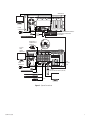
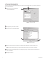
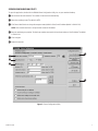
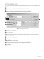
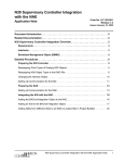
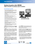
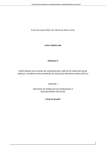
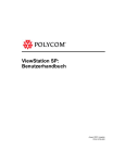
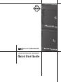
9100 SERIES
VIEWSTATION AND RECORDER
Quick Start Guide
DX9100 Series
A basic DX9100 system consists of a DX9100VS viewstation and a DX9100 recorder. The recorder has an internal storage unit.
The DX9116H models record at a maximum of 15 ips with a hard drive between 500 GB and 1,500 GB. The DX9116F models
record at a maximum of 30 ips with a hard drive between 500 GB and 1,500 GB. You can connect up to 16 cameras to the 16
video input coaxial connectors on the back of the recorder.
CONNECTING THE EQUIPMENT
� Connect the viewstation to the recorder via an Ethernet switch. Use shielded network cables.
NOTE: Use a shielded cable, similar to Belden 1533P, that meets or exceeds the support requirements for ANSI/TIA/EIA
568B.2 cat 5e.
� Connect a monitor, keyboard, and mouse to the viewstation and to the recorder. The monitor, keyboard, and mouse
connected to the recorder are only needed during setup. You can remove them after setup is complete.
� Connect cameras to the BNC connectors on the recorder. The termination switches should be set to the factory default Term
(75 ohms).
� Connect the HASP USB key directly into the bottom right USB port on the recorder. A red light on the key indicates that it is
working properly. The following message will appear on the recorder if you do not plug in the HASP key.
Figure 1. HASP Key Message
� Connect all power cords.
� Turn on the recorder and then the viewstation.
Refer to the DX9100 Digital Video Recorder & Viewstation Installation manual for further connections, such as alarm wiring and
external RS-232 devices.
2
C635M-A-QS (3/09)
VIEWSTATION
POWER
CONNECTION
10/100/1000 BASE-T ETHERNET INTERFACE:
ALLOWS MULTIPLE VIEWSTATIONS
AND RECORDERS
RJ-45
STRAIGHT
CABLES
MAXIMUM OF 16
CAMERA INPUTS
(VIDEO IN)
Term
Loop
1
4
75
HI-Z
LOOPING
VIDEO
SOURCE
(VIDEO OUT)
RECORDER
FOR
FUTURE
USE
POWER
CONNECTION
HASP KEY
(INTO THE BOTTOM RIGHT USB PORT)
CM9760-REL
CM9760-ALM
CM9760-DT
RS-232
Figure 2. System Connections
C635M-A-QS (3/09)
3
SETTING DATE/TIME PROPERTIES
Follow these steps to set the Date/Time Properties on the recorder and the viewstation. Make sure you close all applications on
the recorder and viewstation.
� Double-click the time on the system tray.
The following page appears.
�
�
Figure 3. Date and Time Page
� Set the date and time and then click Apply.
� Click Time Zone. The following page appears.
�
�
�
Figure 4. Time Zone Page
� Select your time zone from the drop-down box. The default is (GMT -08:00) Pacific Time (US & Canada); Tijuana.
NOTE: You must restart the system if you change the default time zone setting on the recorder or viewstation.
� Make sure that the “Automatically adjust clock for daylight saving changes” checkbox is selected, if applicable for the
location of installation.
� Click Apply and then OK.
4
C635M-A-QS (3/09)
SERVER CONFIGURATION UTILITY
To open this application, double-click the DX9000 Server Configuration Utility icon on your recorder’s desktop.
� Set the frame rate and resolution. The number of channels is set automatically.
� Select the recording format. The default is NTSC.
� Click Server Identification to change the computer name (default is Pelco1) and IP address (default is 100.0.0.101).
NOTE: Each recorder must have a unique recorder name and IP address.
� Enter the multicast group number. The last three numbers must match the last three numbers of the IP address. The default
is 239.0.0.101.
� Click Configure.
� Restart the recorder.
�
�
�
�
�
Figure 5. Server Configuration Utility
C635M-A-QS (3/09)
5
CLIENT CONFIGURATION UTILITY
You can find this application on the viewstation. With this application you can build a list of local servers and export them to the
recorders.
� Make sure that the recorder and viewstation are connected to the network switch.
� Go to Start > Programs > DX9000 Viewstation > Client Configuration Utility.
� Log in. The default user name and password is admin/admin. The following page appears.
�
�
�
�
�
Figure 6. Client Configuration Utility Page
� Select “Build a list of local servers.”
� Select “Custom naming.”
NOTE: The Standard naming option is used if all recorders have the same name and the only difference is the numbers. For
example, Pelco1, Pelco2, Pelco3.
� Enter a recorder name and then click Add.
� Click Configure.
NOTE: Repeat steps 6 and 7 for each recorder.
� Select “Export to server” and then the name of the first recorder from the drop-down box.
� Click Configure.
NOTE: Repeat steps 8 and 9 for each recorder that is in the drop-down box.
6
C635M-A-QS (3/09)
TIME SYNCHRONIZATION
Go back to the Server Configuration Utility on the recorder to complete time synchronization.
� Click Suggest to see a list of the recorders that were exported in the Client Configuration Utility.
� Click Configure.
NOTE: Repeat steps 1 and 2 on each physical recorder.
� Restart all recorders and viewstations.
�
Figure 7. Define Time Synchronization
The materials used in the manufacture of this document and its components are compliant to the requirements of Directive 2002/95/EC.
Manual #
C635M-QS
C635M-A-QS
C635M-A-QS (3/09)
Date
8/03
3/09
Comments
Original version.
Revised the DX9100 Viewstation artwork to include a new VGA connector and replaced a VGA connector with a DVI connector.
7
www.pelco.com
Pelco, Inc. Worldwide Headquarters 3500 Pelco Way Clovis, California 93612 USA
USA & Canada Tel (800) 289-9100 Fax (800) 289-9150
International Tel +1 (559) 292-1981 Fax +1 (559) 348-1120
C635M-A-QS (1/09)