1
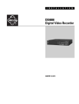
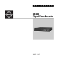
I N S T A L L A T I O N
DX4000
Digital Video Recorder
C2601M-A (6/06)
Contents
Description . . . . . . . . . . . . . . . . . . . . . . . . . . . . . . . . . . . . . . . . . . . . . . . . . . . . . . . . . . . . . . . . . . . . . . . . . . . . . . . . . . . . . . . . . . . . . . . . . . . . . . . . . . 5
Features . . . . . . . . . . . . . . . . . . . . . . . . . . . . . . . . . . . . . . . . . . . . . . . . . . . . . . . . . . . . . . . . . . . . . . . . . . . . . . . . . . . . . . . . . . . . . . . . . . . . . . . . 6
Models . . . . . . . . . . . . . . . . . . . . . . . . . . . . . . . . . . . . . . . . . . . . . . . . . . . . . . . . . . . . . . . . . . . . . . . . . . . . . . . . . . . . . . . . . . . . . . . . . . . . . . . . . 6
About This Manual . . . . . . . . . . . . . . . . . . . . . . . . . . . . . . . . . . . . . . . . . . . . . . . . . . . . . . . . . . . . . . . . . . . . . . . . . . . . . . . . . . . . . . . . . . . . . . . 6
Before You Begin . . . . . . . . . . . . . . . . . . . . . . . . . . . . . . . . . . . . . . . . . . . . . . . . . . . . . . . . . . . . . . . . . . . . . . . . . . . . . . . . . . . . . . . . . . . . . . . . . . . . . 7
Package Contents . . . . . . . . . . . . . . . . . . . . . . . . . . . . . . . . . . . . . . . . . . . . . . . . . . . . . . . . . . . . . . . . . . . . . . . . . . . . . . . . . . . . . . . . . . . . . . . . 7
Front Panel Layout . . . . . . . . . . . . . . . . . . . . . . . . . . . . . . . . . . . . . . . . . . . . . . . . . . . . . . . . . . . . . . . . . . . . . . . . . . . . . . . . . . . . . . . . . . . . . . . . . . . . 8
Video Control Buttons on the Front Panel of the DX4000 . . . . . . . . . . . . . . . . . . . . . . . . . . . . . . . . . . . . . . . . . . . . . . . . . . . . . . . . . . . . . . . . . . 9
Remote Control Layout . . . . . . . . . . . . . . . . . . . . . . . . . . . . . . . . . . . . . . . . . . . . . . . . . . . . . . . . . . . . . . . . . . . . . . . . . . . . . . . . . . . . . . . . . . . . . . . . 10
Connecting Devices to the DX4000 . . . . . . . . . . . . . . . . . . . . . . . . . . . . . . . . . . . . . . . . . . . . . . . . . . . . . . . . . . . . . . . . . . . . . . . . . . . . . . . . . . . . . . 11
Overview of the System . . . . . . . . . . . . . . . . . . . . . . . . . . . . . . . . . . . . . . . . . . . . . . . . . . . . . . . . . . . . . . . . . . . . . . . . . . . . . . . . . . . . . . . . . . . . . . . 13
Operation . . . . . . . . . . . . . . . . . . . . . . . . . . . . . . . . . . . . . . . . . . . . . . . . . . . . . . . . . . . . . . . . . . . . . . . . . . . . . . . . . . . . . . . . . . . . . . . . . . . . . . . . . . 14
Starting and Stopping the DX4000 . . . . . . . . . . . . . . . . . . . . . . . . . . . . . . . . . . . . . . . . . . . . . . . . . . . . . . . . . . . . . . . . . . . . . . . . . . . . . . . . . . 14
Configuring the System . . . . . . . . . . . . . . . . . . . . . . . . . . . . . . . . . . . . . . . . . . . . . . . . . . . . . . . . . . . . . . . . . . . . . . . . . . . . . . . . . . . . . . . . . . . . . . . 15
Date and Time . . . . . . . . . . . . . . . . . . . . . . . . . . . . . . . . . . . . . . . . . . . . . . . . . . . . . . . . . . . . . . . . . . . . . . . . . . . . . . . . . . . . . . . . . . . . . . . . . . 15
Network Settings . . . . . . . . . . . . . . . . . . . . . . . . . . . . . . . . . . . . . . . . . . . . . . . . . . . . . . . . . . . . . . . . . . . . . . . . . . . . . . . . . . . . . . . . . . . . . . . . 16
Changing Network Settings . . . . . . . . . . . . . . . . . . . . . . . . . . . . . . . . . . . . . . . . . . . . . . . . . . . . . . . . . . . . . . . . . . . . . . . . . . . . . . . . . . . 16
Entering an IP Address . . . . . . . . . . . . . . . . . . . . . . . . . . . . . . . . . . . . . . . . . . . . . . . . . . . . . . . . . . . . . . . . . . . . . . . . . . . . . . . . . . . . . . . 18
Configuring Video Recording . . . . . . . . . . . . . . . . . . . . . . . . . . . . . . . . . . . . . . . . . . . . . . . . . . . . . . . . . . . . . . . . . . . . . . . . . . . . . . . . . . . . . . . 18
Upgrading Firmware on the DX4000 . . . . . . . . . . . . . . . . . . . . . . . . . . . . . . . . . . . . . . . . . . . . . . . . . . . . . . . . . . . . . . . . . . . . . . . . . . . . . . . . . . . . . 19
Upgrading Through a Network Connection . . . . . . . . . . . . . . . . . . . . . . . . . . . . . . . . . . . . . . . . . . . . . . . . . . . . . . . . . . . . . . . . . . . . . . . . . . . . 19
Upgrading Through a Direct Connection . . . . . . . . . . . . . . . . . . . . . . . . . . . . . . . . . . . . . . . . . . . . . . . . . . . . . . . . . . . . . . . . . . . . . . . . . . . . . . 21
Verifying Network Connections . . . . . . . . . . . . . . . . . . . . . . . . . . . . . . . . . . . . . . . . . . . . . . . . . . . . . . . . . . . . . . . . . . . . . . . . . . . . . . . . 23
Installing and Updating the Remote Agent Application . . . . . . . . . . . . . . . . . . . . . . . . . . . . . . . . . . . . . . . . . . . . . . . . . . . . . . . . . . . . . . . . . . . . . . . 26
Installing the Web Client . . . . . . . . . . . . . . . . . . . . . . . . . . . . . . . . . . . . . . . . . . . . . . . . . . . . . . . . . . . . . . . . . . . . . . . . . . . . . . . . . . . . . . . . . . . . . . 29
Specifications . . . . . . . . . . . . . . . . . . . . . . . . . . . . . . . . . . . . . . . . . . . . . . . . . . . . . . . . . . . . . . . . . . . . . . . . . . . . . . . . . . . . . . . . . . . . . . . . . . . . . . . 33
C2601M-A (6/06)
3
List of Illustrations
1
2
3
4
5
6
7
8
9
10
11
12
13
14
15
16
17
18
19
20
21
22
23
24
25
26
27
28
29
30
31
32
33
34
35
36
37
38
39
40
41
42
43
4
Package Contents . . . . . . . . . . . . . . . . . . . . . . . . . . . . . . . . . . . . . . . . . . . . . . . . . . . . . . . . . . . . . . . . . . . . . . . . . . . . . . . . . . . . . . . . . . . . . . . . . 7
Front Panel of the DX4000 . . . . . . . . . . . . . . . . . . . . . . . . . . . . . . . . . . . . . . . . . . . . . . . . . . . . . . . . . . . . . . . . . . . . . . . . . . . . . . . . . . . . . . . . . . 8
Control Buttons on the Front Panel. . . . . . . . . . . . . . . . . . . . . . . . . . . . . . . . . . . . . . . . . . . . . . . . . . . . . . . . . . . . . . . . . . . . . . . . . . . . . . . . . . . . 9
Remote Control Operation . . . . . . . . . . . . . . . . . . . . . . . . . . . . . . . . . . . . . . . . . . . . . . . . . . . . . . . . . . . . . . . . . . . . . . . . . . . . . . . . . . . . . . . . . 10
Rear Panel of the DX4000 . . . . . . . . . . . . . . . . . . . . . . . . . . . . . . . . . . . . . . . . . . . . . . . . . . . . . . . . . . . . . . . . . . . . . . . . . . . . . . . . . . . . . . . . . . 11
Connecting Devices to the DX4000 . . . . . . . . . . . . . . . . . . . . . . . . . . . . . . . . . . . . . . . . . . . . . . . . . . . . . . . . . . . . . . . . . . . . . . . . . . . . . . . . . . 13
Connecting Computers Across the Internet . . . . . . . . . . . . . . . . . . . . . . . . . . . . . . . . . . . . . . . . . . . . . . . . . . . . . . . . . . . . . . . . . . . . . . . . . . . . 13
Logging In as the Administrator . . . . . . . . . . . . . . . . . . . . . . . . . . . . . . . . . . . . . . . . . . . . . . . . . . . . . . . . . . . . . . . . . . . . . . . . . . . . . . . . . . . . . 14
Shutting Down the DX4000 . . . . . . . . . . . . . . . . . . . . . . . . . . . . . . . . . . . . . . . . . . . . . . . . . . . . . . . . . . . . . . . . . . . . . . . . . . . . . . . . . . . . . . . . 14
System Menu . . . . . . . . . . . . . . . . . . . . . . . . . . . . . . . . . . . . . . . . . . . . . . . . . . . . . . . . . . . . . . . . . . . . . . . . . . . . . . . . . . . . . . . . . . . . . . . . . . . 15
Date/Time Menu . . . . . . . . . . . . . . . . . . . . . . . . . . . . . . . . . . . . . . . . . . . . . . . . . . . . . . . . . . . . . . . . . . . . . . . . . . . . . . . . . . . . . . . . . . . . . . . . . 16
Network Menu . . . . . . . . . . . . . . . . . . . . . . . . . . . . . . . . . . . . . . . . . . . . . . . . . . . . . . . . . . . . . . . . . . . . . . . . . . . . . . . . . . . . . . . . . . . . . . . . . . 17
Additional Network Settings . . . . . . . . . . . . . . . . . . . . . . . . . . . . . . . . . . . . . . . . . . . . . . . . . . . . . . . . . . . . . . . . . . . . . . . . . . . . . . . . . . . . . . . 18
Firmware Upgrade Message . . . . . . . . . . . . . . . . . . . . . . . . . . . . . . . . . . . . . . . . . . . . . . . . . . . . . . . . . . . . . . . . . . . . . . . . . . . . . . . . . . . . . . . 19
Image Downloader Screen . . . . . . . . . . . . . . . . . . . . . . . . . . . . . . . . . . . . . . . . . . . . . . . . . . . . . . . . . . . . . . . . . . . . . . . . . . . . . . . . . . . . . . . . . 19
Upgrade In Progress Message . . . . . . . . . . . . . . . . . . . . . . . . . . . . . . . . . . . . . . . . . . . . . . . . . . . . . . . . . . . . . . . . . . . . . . . . . . . . . . . . . . . . . . 20
Upgrade Complete . . . . . . . . . . . . . . . . . . . . . . . . . . . . . . . . . . . . . . . . . . . . . . . . . . . . . . . . . . . . . . . . . . . . . . . . . . . . . . . . . . . . . . . . . . . . . . . 20
Firmware Upgrade Message . . . . . . . . . . . . . . . . . . . . . . . . . . . . . . . . . . . . . . . . . . . . . . . . . . . . . . . . . . . . . . . . . . . . . . . . . . . . . . . . . . . . . . . 21
Image Downloader Screen . . . . . . . . . . . . . . . . . . . . . . . . . . . . . . . . . . . . . . . . . . . . . . . . . . . . . . . . . . . . . . . . . . . . . . . . . . . . . . . . . . . . . . . . . 21
Upgrade In Progress Message . . . . . . . . . . . . . . . . . . . . . . . . . . . . . . . . . . . . . . . . . . . . . . . . . . . . . . . . . . . . . . . . . . . . . . . . . . . . . . . . . . . . . . 22
Upgrade Complete . . . . . . . . . . . . . . . . . . . . . . . . . . . . . . . . . . . . . . . . . . . . . . . . . . . . . . . . . . . . . . . . . . . . . . . . . . . . . . . . . . . . . . . . . . . . . . . 22
Network Connections Screen . . . . . . . . . . . . . . . . . . . . . . . . . . . . . . . . . . . . . . . . . . . . . . . . . . . . . . . . . . . . . . . . . . . . . . . . . . . . . . . . . . . . . . . 23
Local Area Connection Status Screen . . . . . . . . . . . . . . . . . . . . . . . . . . . . . . . . . . . . . . . . . . . . . . . . . . . . . . . . . . . . . . . . . . . . . . . . . . . . . . . . 23
Local Area Connection Properties Screen . . . . . . . . . . . . . . . . . . . . . . . . . . . . . . . . . . . . . . . . . . . . . . . . . . . . . . . . . . . . . . . . . . . . . . . . . . . . . 24
Internet Protocol (TCP/IP) Properties Screen . . . . . . . . . . . . . . . . . . . . . . . . . . . . . . . . . . . . . . . . . . . . . . . . . . . . . . . . . . . . . . . . . . . . . . . . . . . 24
Running a Command . . . . . . . . . . . . . . . . . . . . . . . . . . . . . . . . . . . . . . . . . . . . . . . . . . . . . . . . . . . . . . . . . . . . . . . . . . . . . . . . . . . . . . . . . . . . . . 25
Verifying an IP Address . . . . . . . . . . . . . . . . . . . . . . . . . . . . . . . . . . . . . . . . . . . . . . . . . . . . . . . . . . . . . . . . . . . . . . . . . . . . . . . . . . . . . . . . . . . . 25
Remote Agent Installation Screen . . . . . . . . . . . . . . . . . . . . . . . . . . . . . . . . . . . . . . . . . . . . . . . . . . . . . . . . . . . . . . . . . . . . . . . . . . . . . . . . . . . 26
Software License Agreement Screen . . . . . . . . . . . . . . . . . . . . . . . . . . . . . . . . . . . . . . . . . . . . . . . . . . . . . . . . . . . . . . . . . . . . . . . . . . . . . . . . . 26
Select Install Folder Screen . . . . . . . . . . . . . . . . . . . . . . . . . . . . . . . . . . . . . . . . . . . . . . . . . . . . . . . . . . . . . . . . . . . . . . . . . . . . . . . . . . . . . . . . 27
Installation Progress Screen . . . . . . . . . . . . . . . . . . . . . . . . . . . . . . . . . . . . . . . . . . . . . . . . . . . . . . . . . . . . . . . . . . . . . . . . . . . . . . . . . . . . . . . . 27
Warning Message About Overwriting Files . . . . . . . . . . . . . . . . . . . . . . . . . . . . . . . . . . . . . . . . . . . . . . . . . . . . . . . . . . . . . . . . . . . . . . . . . . . . 27
Microsoft DirectX Confirmation Dialog . . . . . . . . . . . . . . . . . . . . . . . . . . . . . . . . . . . . . . . . . . . . . . . . . . . . . . . . . . . . . . . . . . . . . . . . . . . . . . . 28
Installation Complete Screen . . . . . . . . . . . . . . . . . . . . . . . . . . . . . . . . . . . . . . . . . . . . . . . . . . . . . . . . . . . . . . . . . . . . . . . . . . . . . . . . . . . . . . . 28
Confirming the Installation . . . . . . . . . . . . . . . . . . . . . . . . . . . . . . . . . . . . . . . . . . . . . . . . . . . . . . . . . . . . . . . . . . . . . . . . . . . . . . . . . . . . . . . . . 28
Internet Explorer Security Warning . . . . . . . . . . . . . . . . . . . . . . . . . . . . . . . . . . . . . . . . . . . . . . . . . . . . . . . . . . . . . . . . . . . . . . . . . . . . . . . . . . 29
DX4000 Web Client . . . . . . . . . . . . . . . . . . . . . . . . . . . . . . . . . . . . . . . . . . . . . . . . . . . . . . . . . . . . . . . . . . . . . . . . . . . . . . . . . . . . . . . . . . . . . . 29
DX4000 Resource CD Main Screen . . . . . . . . . . . . . . . . . . . . . . . . . . . . . . . . . . . . . . . . . . . . . . . . . . . . . . . . . . . . . . . . . . . . . . . . . . . . . . . . . . 30
DX4000 Utilities . . . . . . . . . . . . . . . . . . . . . . . . . . . . . . . . . . . . . . . . . . . . . . . . . . . . . . . . . . . . . . . . . . . . . . . . . . . . . . . . . . . . . . . . . . . . . . . . .30
Web Client Utility Files . . . . . . . . . . . . . . . . . . . . . . . . . . . . . . . . . . . . . . . . . . . . . . . . . . . . . . . . . . . . . . . . . . . . . . . . . . . . . . . . . . . . . . . . . . . .31
Destination Folder for the Web Client . . . . . . . . . . . . . . . . . . . . . . . . . . . . . . . . . . . . . . . . . . . . . . . . . . . . . . . . . . . . . . . . . . . . . . . . . . . . . . . .31
Web Client Browser Window . . . . . . . . . . . . . . . . . . . . . . . . . . . . . . . . . . . . . . . . . . . . . . . . . . . . . . . . . . . . . . . . . . . . . . . . . . . . . . . . . . . . . . .32
Web Client Log In Screen . . . . . . . . . . . . . . . . . . . . . . . . . . . . . . . . . . . . . . . . . . . . . . . . . . . . . . . . . . . . . . . . . . . . . . . . . . . . . . . . . . . . . . . . . .32
C2601M-A (6/06)
Description
The DX4000 Series digital video recorder (DVR) is an entry-level, professional digital video recorder that not only replaces the traditional VCR and
multiplexer combination but also offers the benefits derived from the latest in digital video processing.
Designed to work with today's broadband networks, the DX4000 uses MPEG-4 compression, allowing the user the ability to view and control the
DVR across a wide area network. Additionally, the smaller file size produced by the MPEG-4 compression standard, allows for longer storage
times compared with traditional DVR technology.
With the ability to record at resolutions up to 704 x 480, the DX4000 Series DVR captures crystal clear pictures, creating effective footage for
later use and retrieval. With the ability to record up to 120 images per second in CIF resolution (352 x 240 NTSC, 352 x 288 PAL), users can also
record full-motion video if desired. Individual adjustments are possible on a per-input basis to optimize the DX4000 to meet a given installation’s
requirements for length of video retention. Video critical for investigation and archiving can be easily exported to a USB flash memory device or
an optional CD-RW.
With the ability to address and control pan/tilt/zoom (PTZ) equipment, such as the Spectra® domes and Esprit® positioning systems, the DX4000
becomes a powerful control point for the surveillance requirements of an installation. In addition, with the ability to trigger recording and alarms
on motion or external contacts, the DX4000 series becomes an automated monitoring and notification engine as well.
The DX4000 video outputs provide for efficient control and effective deterrence. The choice of VGA, S-Video, or composite main monitor outputs
provides flexibility for the user. The main monitor output can be adjusted to display in full screen or quad format. The DX4000's spot monitor can
be used for public view applications, providing an effective deterrent to would-be criminals.
Finally, the DX4000 is designed to deliver robust and reliable performance for security professionals. From the ability to capture log entries
detailing any faults or user-initiated changes to the system, to the inclusion of Pelco's world renowned customer service promise, the DX4000
embodies the ideal entry-level digital video recorder to protect assets and people.
C2601M-A (6/06)
5
FEATURES
•
4-channel, full duplex digital video recorder
•
4-channel audio inputs with one audio output
•
MPEG-4 compression
•
Up to 704 x 480 Recording Resolution
•
Up to 120 images per second recording rate at 352 x 240 resolution
•
Independent channel resolution, quality, and frame rate settings
•
Full-function remote agent with administration functions
•
Up to 500 GB internal storage
•
Support for continuous, motion, and scheduled recording for maximum utilization of hard disk drives
•
Local or remote PTZ control via Pelco D and Pelco P protocols
•
4 alarm inputs, 1 relay output
•
Main monitor output configurable for multiple-camera displays for live and playback video
•
Spot monitor for public view displays
MODELS
Model Number
Camera Inputs
Description
DX4004-160
4
4-channel digital video recorder with 160 GB of storage space
DX4004CD-160
4
4-channel digital video recorder with CD-RW and 160 GB of storage space
DX4004-250
4
4-channel digital video recorder with 250 GB of storage space
DX4004CD-250
4
4-channel digital video recorder with CD-RW and 250 GB of storage space
DX4004-500
4
4-channel digital video recorder with 500 GB of storage space
DX4004CD-500
4
4-channel digital video recorder with CD-RW and 500 GB of storage space
ABOUT THIS MANUAL
This manual contains instructions for installing and configuring the DX4000. It also contains upgrade instructions for the DX4000 firmware and
for the remote agent software application that is installed on a computer. For basic operation instructions, refer to Front Panel Layout on page 8.
For details about operating the unit; instructions on how to search for, play back, and back up video; and information on installing and using the
remote agent application, refer to the DX4000 Operation manual.
6
C2601M-A (6/06)
Before You Begin
Before you install the DX4000, review the package contents to ensure that it contains all parts.
PACKAGE CONTENTS
SHIPPING BOX
DX4000
WITH OPTIONAL CD-RW
ACCESSORY PACK
ACCESSORY PACK
USA
STANDARD POWER
CORD (110 VAC)
1 EA.
EUROPEAN
STANDARD POWER
CORD (220 VAC)
1 EA.
SAFETY INSTRUCTIONS
INSTALLATION MANUAL
12 VDC ADAPTER
UK
STANDARD POWER
CORD (250 VAC)
1 EA.
RESOURCE CD WITH
OPERATION MANUAL
CLIENT SOFTWARE
REMOTE
CONTROL
AAA BATTERIES (2)
Figure 1. Package Contents
Qty
C2601M-A (6/06)
Description
1
Digital video recorder with built-in hard disk drive. Some models contain two hard disk drives. Some models contain an
optional writable CD drive (CD-RW).
3
Power cords (1 USA standard, 1 European standard, 1 UK standard)
1
12V adapter for use with power cords
1
Remote control
1
Battery pack (2 AAA batteries) for the remote control
1
Resource CD with operation manual and remote agent program software
1
Installation manual
7
Front Panel Layout
Figure 2. Front Panel of the DX4000
The buttons on the front panel of the unit control PTZ and camera focus, to enter menus and adjust settings on the DX4000, and to search for and
play back video. Refer to Figure 2 for the locations of the buttons on the front panel.
Remote control sensor input: Receives data from the remote control.
Power: Turns the unit on or off.
USB port: Connects a USB flash memory device to back up video.
CD-RW: Stores backup copies of recorded video on a writable compact disc (available on certain models).
Unit status indicators: Indicates operating status as follows:
PWR: The system is on or off.
•
REC: The system is recording.
•
NET: The remote agent is connected to the DX4000.
•
ALARM: The alarm sensor has detected an event.
Channel selection buttons: Selects a channel (1-4) or lets you input a password.
SCR MODE: Selects the screen layout mode or video sequencing mode.
MENU: Opens the system menus.
SEARCH: Starts the search mode for data searches.
PTZ/FOCUS: Accesses the PTZ/FOCUS controls for a camera.
8
•
Control buttons: Navigate through menu options or control recorded video. Refer to Video Control Buttons on the Front
Panel of the DX4000 on page 9 for a description of the buttons.
RETURN: Cancels a setup operation or returns you to a previous menu or mode.
ENTER: Applies any changes that you enter and accesses selected menus.
C2601M-A (6/06)
VIDEO CONTROL BUTTONS ON THE FRONT PANEL OF THE DX4000
Figure 3. Control Buttons on the Front Panel
C2601M-A (6/06)
Fast reverse: Plays the video backward at a fast speed.
Increase forward or reverse: Increases the speed of the currently playing direction (forward or reverse).
Play forward: Plays the video forward.
Fast forward: Plays the video forward at a fast speed.
Play reverse: Plays the video in reverse.
Decrease forward or reverse: Decreases the speed of the currently playing direction (forward or reverse).
Pause: Stops the video and displays the current frame of the video.
9
Remote Control Layout
The diagram below describes the buttons on the remote control that operate the DX4000. Each button has a corresponding function on the front
panel of the unit. The remote control is operable only when the remote control sensor on the DX4000 is enabled. If several DX4000 units are
located close together, the remote control might operate more than one unit. Care should be taken to locate similar devices away from each
other. Buttons that are not usable are not described.
Figure 4. Remote Control Operation
10
Power button: Turns the system on or off.
Return button: Cancels setup commands or returns to a previous menu or screen.
Menu button: Opens the main menu.
Channel selection buttons: Selects the available channels (up to a maximum of four).
Enter button: Applies any configuration changes made to the DX4000.
Direction control buttons: Navigate through menu options or control recorded video.
Screen Mode button: Changes the screen display between a full screen and four video panes (quad view).
F1: Creates a preset action.
Search button: Opens the search dialog box.
PTZ/Iris mode: Places the camera in PTZ or focus mode.
F2: Selects a preset action.
C2601M-A (6/06)
Connecting Devices to the DX4000
Use the following diagram of the rear panel of the DX4000 to determine how to connect devices to the unit.
3
4
2
1
L
1
2
3
4
1
3
2
4
L
NTSC
PAL
12
SEQ
Figure 5. Rear Panel of the DX4000
WARNING: To avoid electric shock, turn off the unit and unplug it while connecting devices to the DX4000. Adequate ventilation is
required for proper operation of the DX4000. Allow two inches of space above the unit and on each side for air circulation.
1. Connect up to four cameras at the video inputs. Refer to Table A for video coaxial cable distances. The DX4000 features automatic
termination of video if no loop out cables are attached. Remove all unused cables from the video output ports.
2. If desired, connect analog monitors to the video outputs (looping). Refer to Table A for video coaxial cable distances. You must terminate all
monitors. If you connect a single monitor to an output, terminate the monitor at 75 ohms. If you connect more than one monitor to an
output, terminate the farthest monitor at 75 ohms, and terminate the others at Hi-Z. Remove all unused cables.
3. If desired, connect an analog monitor to the main monitor output. Refer to Table A for video coaxial cable distances. If you connect more
than one monitor to an output, terminate the farthest monitor at 75 ohms, and terminate the others at Hi-Z.
4. If desired, connect a spot monitor to the DX4000. Refer to Table A for video coaxial cable distances. If you connect more than one monitor
to an output, terminate the farthest monitor at 75 ohms, and terminate the others at Hi-Z. Note that you can view live video from a spot
monitor. To search for and play back video or to configure the DX4000, you must be working at the unit and main monitor or at a remote
computer.
Table A. Video Coaxial Cable Requirements
Cable Type*
Maximum Distance
RG59/U
750 ft (229 m)
RG6/U
1,000 ft (305 m)
RG11/U
1,500 ft (457 m)
*Cable requirements:
75 ohms impedance
All-copper center conductor
All-copper braided shield with 95% braid coverage
5. Select the video stream type for the cameras. Choices are NTSC or PAL.
WARNING: Changing the video stream type from NTSC to PAL reformats the hard disk. Do not change video stream types until any
recorded video has been backed up to CD or a removable USB flash memory device.
C2601M-A (6/06)
11
6. If desired, connect a VGA monitor to the VGA port.
7. If desired, connect a monitor that accepts S-Video to the SVHS port. Refer to Table A for video coaxial cable distances.
8. If you want to receive audio transmissions from the remote agent on a computer, connect an audio cable to the audio output jack. Refer to
Table A for video coaxial cable distances.
9. If you want to record audio along with video, connect up to four audio feeds from the cameras to the audio input jacks. Before recording
audio, consult your location’s applicable laws regarding audio surveillance.
10. Connect an Ethernet cable at the Ethernet (TCP/IP) port to connect the DX4000 to remote users across a network.
11. Connect alarm inputs, relay outputs, and PTZ connections as follows:
•
•
•
Alarm inputs: You can have one alarm for each camera. Connect one alarm lead to the IN1, IN2, IN3, or IN4 input, and the other alarm
lead to the ground input. Alarms can be programmed for normally open or normally closed inputs.
Relay outputs: Connect a relay to the normally open (NO), normally closed (NC), or common (COM) outputs. The relay is rated for I A
at 30 VDC or 0.5 A at 125 VAC.
PTZ connections: Connect the leads for controlling a PTZ camera from the RX+ and RX- leads on the camera to the TX+ and TXconnectors on the DX4000. To connect several cameras with PTZ capabilities, daisy-chain the cameras.
12. If necessary, connect a computer directly to the DX4000 with a DB9 cable. This connection is for use only by service technicians while
resolving problems with the unit.
13. Connect the 12 VDC adaptor to the DX4000. Connect one of the supplied power cords to the adapter, and then connect the other end of the
power cord to a source of power.
12
C2601M-A (6/06)
Overview of the System
The DX4000 serves as the center of a video surveillance system to which many computers can be connected. Figure 4 illustrates that computers
can be connected either directly to the DX4000 or remotely over a network. Figure 4 shows the maximum number of cameras and alarm sensors
that can be connected to the DX4000. In this illustration you will also note that monitors can be connected to the system and can be placed
around the building for live viewing of specific cameras. Two types of backup devices are connected to the DX4000: a writable CD drive and a
USB flash memory device. Refer to Figure 7 for an example of how computers can be connected to the DX4000 over the Internet.
ALARM SENSOR
#1-4
PC MULTIMEDIA
SPEAKER
RELAY OUT
MAIN
MONITOR
REMOTE PC
DX4000
NETWORK
CAMERAS
#1-4
OPTIONAL
CD-RW
PC
MULTIMEDIA
SPEAKER
SPOT
MONITOR
REMOTE CLIENT
USB KEY
REMOTE
CONTROLLER
AUDIO IN
#1-4
REMOTE PC
WEB CLIENT
Figure 6. Connecting Devices to the DX4000
INTERNET
CLIENT PC
ROUTER
xDSL
MODEM
MONITOR
DX4000
CLIENT PC
Figure 7. Connecting Computers Across the Internet
C2601M-A (6/06)
13
Operation
Refer to the DX4000 Operation manual for details on how to access the system features and navigate the menus. The operation manual is
located on the resource CD that came with your unit.
STARTING AND STOPPING THE DX4000
Press the power button on the front panel of the DX4000 to start it. The first time you start the DX4000, you must log on as the administrator.
For future sessions, you can log on as any of the users after you configure the system.
To start the DX4000
1. Press the power button on the front panel of the DX4000 if it is not already running. The Setup screen appears and the Administrator user
is selected.
2. Press the numbered channel buttons to enter the default password (1234), and then press the Enter button.
Figure 8. Logging In as the Administrator
To stop the DX4000
1. Press the power button on the front panel of the DX4000. The unit beeps and displays the Shutdown screen.
2. Press the numbered channel buttons to enter your password, and then press the Enter button. The unit shuts down all attached devices and
then turns off.
Figure 9. Shutting Down the DX4000
14
C2601M-A (6/06)
Configuring the System
Before you use the DX4000 to record and monitor video, you should configure the system settings discussed below.
DATE AND TIME
The Date/Time menu contains the following options for controlling date and time on the DX4000:
•
Date: Choose this option to set the date on the DX4000. This date establishes the internal calendar for the DX4000, and all recorded video
is based on this setting.
•
Date Format: Choose a date format that you want to display on the video panels. This format is saved with the video as it is recorded.
Choices are yyyy/mm/dd, mm/dd/yyyy, and dd/mm/yyyy.
•
Time: Choose this option to set the current time on the DX4000. This time establishes the internal clock on the DX4000, and all recorded
video is based on this setting.
•
Time Format: Choose a time format that you want to display on the video panels. This format is saved with the video as it is recorded.
Choices are 24 hour and AM/PM.
•
Daylight Saving: Select this setting if you are in a state or country that follows daylight saving time. This setting ensures that recorded
video displays the proper time when clocks are changed to reflect daylight saving time each year. You must select Daylight Saving time on
both the DX4000 and the computer on which the remote agent is running. Use the Time Zone tab on the Date and Properties screen on the
remote computer to adjust its clock automatically for daylight saving changes. Refer to the operation manual for instructions on configuring
the system from the remote agent application.
•
Time Zone: Select the time zone in which the DX4000 is located. Time zones are determined based on the number of hours they are offset
from Greenwich Mean Time (GMT). Time zones are also associated with a major city. As you select a time, the city is listed on the line
below.
To set the date and time
1. Press the Menu button on the front panel of the DX4000. The Setup screen appears.
2. Enter your password, and then press the Enter button.
3. Press the down arrow button until the System menu is selected, and then press the Enter button. The System menu appears and Date/Time
is the first available option.
Figure 10. System Menu
C2601M-A (6/06)
15
4. Select the Date/Time option if it is not already selected, and then press the Enter button. The Date/Time menu appears.
Figure 11. Date/Time Menu
5. Adjusting each portion of a date is a two-step process. Use the right and left arrow buttons to select a portion of the date (for example, the
year), and then press the Enter button to select it. The setting changes color. Press the up and down arrow buttons until the setting is
correct. Press the Enter button to accept the changes to the setting. Repeat the process for the month and day.
6. Set the time for the system in the same manner. Select the hour, minutes, and seconds separately.
7. If you are in a state or country that observes Daylight Saving Time, move to Daylight Saving and turn it on. You must also enable daylight
savings on your computer if you intend to use the remote agent to review and record video. Follow the instructions for your computer
operating system to adjust the clock for daylight savings changes.
8. Select a time zone. Time zones are determined in relation to Greenwich Mean Time (GMT). To enter a time zone select the number of hours
that your time zone offset from GMT. As you select a time, the time zone is listed below.
9. After you have configured all of the settings, press the Enter button on the front panel of the DX4000 to accept your changes.
10. Press the Return button until all menus are cleared from the screen. Note that the “Saving Setup” message appears on the screen.
NETWORK SETTINGS
If you will access the DX4000 from the remote agent application on a computer, you must configure your network settings. You must restart the
system before the changes take effect. Be sure that you are not recording any video that cannot be interrupted before you change network
settings. The Network menu contains the following menu options for controlling network settings on the DX4000:
•
DHCP: Use this option if the DX4000 uses Dynamic Host Configuration Protocol to connect to remote agents over the Internet.
•
DDNS: Use this option if your system uses a dynamic domain name service.
•
WEB Server: Use this option if the users will connect to the DX4000 with the Web client to view live video.
•
Network Speed: Use this option to limit the transmission rate used by your network. Options include 56, 128, 256, 512, 1024, 2048, 4098,
and 8192 Kbps. Lower network bandwidths slow the video transmission rate.
CHANGING NETWORK SETTINGS
1. Press the Menu button on the front panel of the DX4000. The Setup screen appears. Refer to Figure 8.
2. Enter your password, and then press the Enter button. The Main menu appears.
3. Press the down arrow button until the System option is selected, and then press the Enter button.
16
C2601M-A (6/06)
4. Press the down arrow button until the Network option is selected, and then press the Enter button. The Network menu appears.
Figure 12. Network Menu
5. Enable or disable the settings to fit your system. Adjusting a setting is a two-step process. Press the up or down arrow buttons to select a
setting, and then press the Enter button. A setting changes color when it is selected. Press the up or down arrow buttons until the setting is
correct, and then press the Enter button to save the change.
a.
DHCP: Enable DHCP if your system uses dynamic Internet addresses.
b.
DDNS: Enable DDNS if your system uses a dynamic domain name service.
c.
WEB Server: Enable the WEB Server if your users will use the Web client to view live video over the Internet.
d.
Network Speed: Select the desired baud rate for your network.
6. Press the down arrow button until the Next command is selected, and then press the Enter button. Additional network settings appear.
7. Configure any additional settings that are required for your network. Whether the following settings will be available depends on which
network options you selected (refer to Figure 13):
•
Web Server Port: Enter the port number that the Web Client will use to communicate with the DX4000 over the Internet. The default
port number is 80.
WARNING: If you use the Web Client to access the DX4000 and you change the port number, you must update the IP address on the
web address to include the new port number. The revised IP address would resemble the following: http://192.168.0.40:8080, where
8080 is the revised port number.
•
•
•
•
•
•
•
C2601M-A (6/06)
Client Service Port: Enter the port number that the remote agent will use to communicate with the DX4000. The default port number
is 6100. You may use a different working port number.
DDNS Server: Verify the name of the Dynamic Domain Name Service. The default service name is DDNS.DVRLINK.NET. If your
network uses a different service, enter it here. Note that entering the name incorrectly will render the service inoperable.
IP Address: If your network uses static IP addresses, enter it here. A default IP address for the DX4000 can be found on the System
Information menu. Refer to Entering an IP Address on page 18 for instructions for entering an IP address.
Gateway: Enter the IP address for the Internet gateway server. On smaller systems, this will be the IP address of the DX4000. On larger
systems, there might be a separate machine that serves as the gateway.
Subnet Mask: Enter the IP address of the subnet mask for the DX4000.
1st DNS Server: Enter the IP address of the primary Domain Name Service server that the DX4000 will use to convert names to
IP addresses. If you intend to use the DDNS server, you do not need to enter a DNS server.
2nd DNS Server: Enter the IP address of the backup Domain Name Service server that the DX4000 will use to convert names to
IP addresses. This server is used if the primary DNS server fails. If you intend to use the DDNS server, you do not need to enter a
DNS server.
17
ENTERING AN IP ADDRESS
If you use DHCP to derive IP addresses, you do not need to set up an IP address for the DX4000. Follow these steps to set up the IP address for
the DX4000 if DHCP has been turned off:
1. Select the System menu from the main menu of the DX4000, and then select Network.
2. On the Network menu, turn off DHCP.
3. Move to the Next command, and then press the Enter button. Additional IP address settings appear on the menu.
Figure 13. Additional Network Settings
4. Move to the IP address field. An IP address contains four parts. Set each part as follows:
a.
Press the Enter button to select each part of the IP address.
b.
Press the up or down arrow buttons on the DX4000 until the correct number is displayed.
c.
Press the right or left arrow buttons to move to the next or previous part of the address.
d.
Repeat steps a through c to change all four parts of the address.
e.
Press the Return button until all menus are cleared from the screen and the address has been saved.
5. Restart the DX4000 to save and activate the network changes.
CONFIGURING VIDEO RECORDING
By default, the DX4000 is set up for continuous recording. You can set up a schedule to record video only at certain times or to record video in
response to alarms or motion. To change the default recording settings, refer to the operation manual for additional information.
18
C2601M-A (6/06)
Upgrading Firmware on the DX4000
Firmware resides in the flash memory of the main board of the DX4000. To upgrade the firmware on the DX4000, you must run an upgrade
program from a computer that is connected to the unit through a network. The process varies depending on the connection type: network or
direct. Follow the upgrade instructions for the type of network connection you use. Note that you must also upgrade the remote agent application
if you intend to work with the DX4000 from a remote computer.
UPGRADING THROUGH A NETWORK CONNECTION
Follow these instructions if your DX4000 is connected to a computer through a network.
1. Turn off the DX4000 and disconnect the power cable.
2. While holding down the Menu and Enter buttons simultaneously, reconnect the power cable. A message resembling the following appears.
Figure 14. Firmware Upgrade Message
3. Make a note of the IP address on this message.
4. From a remote computer that is connected to the DX4000 through a network connection, locate the upgrade files. These files can be located
on the resource CD or on a network drive. The names of these files might be different for each upgrade. The following file names are
examples of what you should find:
•
•
•
FirmwareUpgradeUtility.exe: This is the upgrade program that contains the software version number that you will install.
DVR4000ver.1.0.img: This is the actual updated firmware file that will be copied to the DX4000.
DX4000RemoteAgent.exe: This is the installation program for the revised remote agent that you must install to communicate with
the upgraded DX4000. For instructions on updating the remote agent software, refer to Installing and Updating the Remote Agent
Application on page 26.
5. After you have located these files, double-click the upgrade program to start the installation. The Image Downloader screen appears.
Figure 15. Image Downloader Screen
C2601M-A (6/06)
19
6. Update the information on the screen as follows, and then click the Download button.
•
•
•
In the Target IP field, enter the IP address for the DX4000 that you noted in step 3.
Check the box for Download Only Application Image.
Click the Browse button next to the Image Path field, and then select the image file that you located in step 4.
7. Track the upgrade process on the DX4000 monitor. A message at the bottom of the screen indicates the progress.
Figure 16. Upgrade In Progress Message
8. After the upgrade process has finished, a message appears on the screen asking you to restart the system.
Figure 17. Upgrade Complete
9. Press the Power button to restart the DX4000.
10. On the remote computer, click the Exit button to close the installation program.
11. Refer to To install or update the Remote Agent on page 26 to upgrade the software on the remote agent before you reconnect to the
DX4000 from a remote computer.
20
C2601M-A (6/06)
UPGRADING THROUGH A DIRECT CONNECTION
Follow these instructions if you are connected to the DX4000 from a remote computer with a crossover cable. This computer also must have
access to upgrade files either on a network drive or a CD.
1. Connect the remote computer to the DX4000 with a crossover cable.
2. Turn off the DX4000 and disconnect the power cable.
3. While holding down the SCR Mode and Return buttons simultaneously, reconnect the power cable. A message resembling the following
appears.
Figure 18. Firmware Upgrade Message
4. Make a note of the IP address and subnet mask that are listed on the message, and then follow the instructions at Verifying Network
Connections on page 23 to verify that your remote computer is in the same subnet range as the DX4000.
5. From a remote computer, locate the upgrade files. These files can be located on a resource CD or on a network drive. The names of these
files might be different for each upgrade. The following file names are examples of what you should find:
•
•
•
FirmwareUpgradeUtility.exe: This is the upgrade program that contains the software version number that you will install.
DVR400ver.1.0.img: This is the actual updated firmware file that will be copied to the DX4000.
DX4000RemoteAgent.exe: This is the installation program for the revised remote agent that you must install to communicate with
the upgraded DX4000. For instructions on updating the remote agent software, refer to Installing and Updating the Remote Agent
Application on page 26.
6. Double-click the upgrade program to start the installation process. The Image Downloader screen appears.
Figure 19. Image Downloader Screen
C2601M-A (6/06)
21
7. Update the information on the screen as follows, and then click the Download button.
•
•
•
In the Target IP field, enter the IP address for the DX4000 that you noted in step 4.
Check the box for Download Only Application Image.
Click the Browse button next to the Image Path field, and then select the image file that you located in step 5.
8. Track the upgrade process on the DX4000 monitor. A message at the bottom of the screen indicates the progress.
Figure 20. Upgrade In Progress Message
9. After the upgrade process has finished, a message appears on the screen asking you to restart the system.
Figure 21. Upgrade Complete
10. Press the Power button to turn off the DX4000. Press the Power button again to restart it.
22
C2601M-A (6/06)
VERIFYING NETWORK CONNECTIONS
Since upgrading the firmware on the DX4000 from a computer connected by a crossover cable does not rely on DHCP to assign the IP address on
the DX4000, make sure that your computer is in the same subnet range as the DX4000. To verify this you can review the network connections
settings for the remote computer. The following instructions are based on Windows XP®. These instructions may vary if you are running a
different operating system.
1. Open the Start menu on the remote computer, and then select Control Panel.
2. Select Network and Internet Connections, and then select Network Connections. The Network Connections screen appears.
Figure 22. Network Connections Screen
3. Double-click Local Area Connection. The Local Area Connection Status screen appears.
Figure 23. Local Area Connection Status Screen
4. Click Properties. The Local Area Connection Properties screen appears.
C2601M-A (6/06)
23
Figure 24. Local Area Connection Properties Screen
5. Select Internet Protocol (TCP/IP) and click the Properties. The Internet Protocol (TCP/IP) Properties screen appears.
Figure 25. Internet Protocol (TCP/IP) Properties Screen
6. Select “Use the following IP address”, enter the IP address and subnet mask for the DX4000, and then click the OK button. Use the
information that you noted in step 4 of Upgrading Through a Direct Connection on page 21.
7. Click Close on both the Internet Protocol (TCP/IP) Properties and Local Area Connection Status screens.
8. From the Start menu click Run ... to open a command prompt. The following screen appears.
24
C2601M-A (6/06)
Figure 26. Running a Command
9. Type the ping command followed by the IP address that you entered in step 6, and then press the Enter key on your keyboard. The command
would resemble the following:
ping 192.168.50.2
If the IP address is correct, a DOS window appears with a series of messages.
Figure 27. Verifying an IP Address
If the IP address is not correct, the DOS windows appears with a series of time out messages. Check the IP address again, or contact a
network administrator to determine the correct address.
10. Close the DOS window by clicking the X in the upper-right corner.
C2601M-A (6/06)
25
Installing and Updating the Remote Agent Application
The DX4000 remote agent application is designed to run on a computer using Microsoft® Windows® operating systems. Refer to Specifications
on page 33 for a list of supported versions of the Windows operating systems. You can install the remote agent application from the resource CD
that came with your unit. If you intend to use the remote agent application from several computers on a network, you can copy the installation
files from the CD onto a network drive.
After you upgrade the firmware on the DX4000, you must update the remote agent application software as well. Updated software for the
remote agent application is provided along with firmware updates. These files are provided on a CD-ROM or on a network drive. The names of
these files will be different for each upgrade. The following files names are examples of what you should find:
•
•
•
FirmwareUpgradeUtility.exe: This is the upgrade program that contains the software version number that you will install.
DVR4000ver.1.0.img: This is the actual updated firmware file that will be copied to the DX4000.
DX4000RemoteAgent.exe: This is the installation program for the revised remote agent application that you must install to communicate
with the upgraded DX4000.
To install or update the Remote Agent
1. Locate the remote agent software installation program either on the resource CD or a network drive.
2. Double-click the file to start it. For example, in the examples above, you would double-click the file called DX4000RemoteAgent.exe.
The installation screen appears.
Figure 28. Remote Agent Installation Screen
3. Click Next. The Software License Agreement screen appears.
Figure 29. Software License Agreement Screen
26
C2601M-A (6/06)
4. Review the license agreement, select the “I accept this License Agreement” check box, and then click Next. The Choose Install Folder
screen appears.
Figure 30. Select Install Folder Screen
5. Click Install to accept the default installation folder, or click the Browse button to select a different folder, and then click Install. As the
software is installed, a progress screen is updated.
Figure 31. Installation Progress Screen
6. If you are installing a newer version of the DX4000 remote agent in the same directory as a previous version, a message appears asking if
you want to overwrite the files. Click Yes for each file.
Figure 32. Warning Message About Overwriting Files
C2601M-A (6/06)
27
7. If your computer contains a version of Microsoft® DirectX® that is older than version 7.0, you will be prompted to install it.
Figure 33. Microsoft DirectX Confirmation Dialog
8. Click Yes to install this application, and then follow the instructions on the screen to install Microsoft DirectX.
9. After all files have been successfully installed on your computer, the Installation Complete screen appears.
Figure 34. Installation Complete Screen
10. Click Next to complete the installation. A confirmation screen appears.
Figure 35. Confirming the Installation
11. Click Finish, and the installation or update will be complete.
For information on configuring and running the remote agent application, refer to the operation manual.
28
C2601M-A (6/06)
Installing the Web Client
The DX4000 Web client provides remote access to the DX4000 so that you can monitor live video across the Internet. To search for or play back
recorded video or to update system settings, you must use the remote agent, the controls on the front panel of the DX4000, or the remote control.
For instructions on viewing live video from the Web client, refer to the operation manual.
The Web client application must be installed on your computer the first time you try to use it. You can then open it on your computer and run it by
opening the program from a web browser. To access the DX4000 through an Internet browser, you must be connected remotely to the DX4000
through a network. You cannot use the Web client on computers that are connected directly to the DX4000 with a crossover cable.
The Web client application can be downloaded directly from the Pelco web site if you have a direct connection to the Internet. Refer to To install
the Web client with a direct Internet connection, below, for instructions on installing the Web client from the Pelco web site. If you do not have
direct access to the Internet, you can install these files from the resource CD that was provided with your unit. Refer to To install the Web client
from the resource CD on page 30 for instructions on installing these files from the resource CD.
To install the Web client with a direct Internet connection
1. From any computer with an Internet connection, start Internet Explorer.
2. Enter the IP address of the DX4000 in the Address line, and then press the Enter key on your keyboard. The following installation security
warning appears.
Figure 36. Internet Explorer Security Warning
3. Click the Install button. The Web client application is installed automatically on your computer and is opened in the web browser window.
Figure 37. DX4000 Web Client
TIP: Create a bookmark for the application in your web browser so that you can open the Web client quickly in the future.
C2601M-A (6/06)
29
To install the Web client from the resource CD
1. Load the DX4000 resource CD in your CD-ROM drive. The following screen appears.
Figure 38. DX4000 Resource CD Main Screen
2. Click DX4000 Utilities. A list of utility files appears.
Figure 39. DX4000 Utilities
3. Click DVR Web Client Utility. A list of files for the Web client appears.
30
C2601M-A (6/06)
Figure 40. Web Client Utility Files
4. Select both files and then copy them to any directory on your computer. For example, you might copy them to a folder called C:\Program
Files\Pelco\DX4000\Webclient.
Figure 41. Destination Folder for the Web Client
5. To run the Web client, select the file called webdvr.html from the directory on your computer, and then open it with Internet Explorer.
The Web client opens in a browser window.
C2601M-A (6/06)
31
Figure 42. Web Client Browser Window
6. Click the Connect button. The Log In screen appears.
Figure 43. Web Client Log In Screen
7. Enter the following information to connect to the DX4000, and then click OK.
•
•
•
•
IP address: Enter the IP address of the DX4000.
Port: Enter the port number of the DX4000. The default port number is 6100.
ID: Select a user ID from the list. For best results, do not use the Administrator ID.
Password: Enter the pasword for the user ID that you selected. The default password is 1234.
The Web client opens and displays live video. You must enter the correct login information each time you start the Web client.
32
C2601M-A (6/06)
Specifications
COMPATIBLE PRODUCTS
Esprit positioning systems, Spectra domes
ELECTRICAL/VIDEO
Input Voltage
100-240 VAC, 50/60 Hz, autoranging
Power Consumption
60 W
Signal System Standard
NTSC/PAL switchable
Recording Resolutions
NTSC
704 x 480
704 x 240
352 x 240
Video Inputs
4, composite, looping, with automatic termination
Video Outputs
4, composite, looping, with automatic termination
2, composite, main and spot monitors
1, VGA
1, SVHS
Video Compression
MPEG-4
Remote Connection
LAN/WAN/TCP/IP
10/100 Mbps
Network port
Remote Administration
Full remote control via TCP/IP network
Total Recording Rate
Up to 120 images per second
PAL
704 x 576
704 x 288
352 x 288
MECHANICAL
Connectors
Video Inputs
4, BNC
Video Outputs
4, BNC, looping
2, BNC, main and spot monitors
1, VGA
1, SVHS
Audio Inputs
4, RCA sockets
Audio Output
1, RCA socket
Alarm Input
4, N.O. or N.C., selectable
Relay Output
1, (N.O. or N.C.), 1 A at 30 VDC/0.5 A at 125 VAC, resistive
TCP/IP Port
RJ-45, 10/100 Mbps
COM 1
RS-232C, for use by technicians while repairing the unit
USB Port
1 USB 1.1
RS-485
PTZ control
SVHS
1 optional S-Video monitor
GENERAL
Operating Temperature
32° to 95°F (0° to 35°C)
Relative Humidity
Maximum 80%, noncondensing
Dimensions
2.6" H x 14.17" W x 14.17" D (6.6 x 36 x 36 cm)
Unit Weight
13.22 lb (6 kg)
Shipping Weight
TBD
C2601M-A (6/06)
33
CERTIFICATIONS
•
CE, Class A
•
UL Listed (external power supply)
•
FCC, Class A
REMOTE AGENT
34
Operating System
Microsoft Windows 2000 or Windows XP
Processor
Intel® Pentium® IV, 2.4 GHz
Memory
256 MB RAM
Video Card
ATI® Radeon® 7000 graphics board, Matrox® Millennium G450 graphics card, or NVIDIA® GeForce®2
series graphics processing unit
C2601M-A (6/06)
PRODUCT WARRANTY AND RETURN INFORMATION
WARRANTY
Pelco will repair or replace, without charge, any merchandise proved defective in material or
workmanship for a period of one year after the date of shipment.
Exceptions to this warranty are as noted below:
• Five years on FR/FT/FS Series fiber optic products and TW3000 Series unshielded twisted
pair transmission products.
• Three years on Genex ® Series products (multiplexers, server, and keyboard).
• Three years on Camclosure ® and fixed camera models, except the CC3701H-2,
CC3701H-2X, CC3751H-2, CC3651H-2X, MC3651H-2, and MC3651H-2X camera models,
which have a five-year warranty.
• Three years on PMCL200/300/400 Series LCD monitors.
• Two years on standard motorized or fixed focal length lenses.
• Two years on Legacy®, CM6700/CM6800/CM9700 Series matrix, and DF5/DF8 Series
fixed dome products.
®
®
™
• Two years on Spectra , Esprit , ExSite , and PS20 scanners, including when used in
continuous motion applications.
• Two years on Esprit® and WW5700 Series window wiper (excluding wiper blades).
• Two years (except lamp and color wheel) on Digital Light Processing (DLP ®) displays.
The lamp and color wheel will be covered for a period of 90 days. The air fi lter is not
covered under warranty.
• Eighteen months on DX Series digital video recorders, NVR300 Series network video
recorders, and Endura ™ Series distributed network-based video products.
• One year (except video heads) on video cassette recorders (VCRs). Video heads will be
covered for a period of six months.
• Six months on all pan and tilts, scanners or preset lenses used in continuous motion
applications (that is, preset scan, tour and auto scan modes).
Pelco will warrant all replacement parts and repairs for 90 days from the date of Pelco
shipment. All goods requiring warranty repair shall be sent freight prepaid to Pelco, Clovis,
California. Repairs made necessary by reason of misuse, alteration, normal wear, or accident
are not covered under this warranty.
Pelco assumes no risk and shall be subject to no liability for damages or loss resulting from
the specific use or application made of the Products. Pelco’s liability for any claim, whether
based on breach of contract, negligence, infringement of any rights of any party or product
liability, relating to the Products shall not exceed the price paid by the Dealer to Pelco for
such Products. In no event will Pelco be liable for any special, incidental or consequential
damages (including loss of use, loss of profit and claims of third parties) however caused,
whether by the negligence of Pelco or otherwise.
The above warranty provides the Dealer with specific legal rights. The Dealer may also have
additional rights, which are subject to variation from state to state.
If a warranty repair is required, the Dealer must contact Pelco at (800) 289-9100 or
(559) 292-1981 to obtain a Repair Authorization number (RA), and provide the following
information:
1. Model and serial number
2. Date of shipment, P.O. number, Sales Order number, or Pelco invoice number
3. Details of the defect or problem
If there is a dispute regarding the warranty of a product which does not fall under the
warranty conditions stated above, please include a written explanation with the product
when returned.
Method of return shipment shall be the same or equal to the method by which the item was
received by Pelco.
RETURNS
In order to expedite parts returned to the factory for repair or credit, please call the factory at
(800) 289-9100 or (559) 292-1981 to obtain an authorization number (CA number if returned
for credit, and RA number if returned for repair).
All merchandise returned for credit may be subject to a 20% restocking and refurbishing
charge.
Goods returned for repair or credit should be clearly identified with the assigned CA or RA
number and freight should be prepaid. Ship to the appropriate address below.
If you are located within the continental U.S., Alaska, Hawaii or Puerto Rico, send goods to:
Service Department
Pelco
3500 Pelco Way
Clovis, CA 93612-5699
If you are located outside the continental U.S., Alaska, Hawaii or Puerto Rico and are
instructed to return goods to the USA, you may do one of the following:
If the goods are to be sent by a COURIER SERVICE, send the goods to:
Pelco
3500 Pelco Way
Clovis, CA 93612-5699 USA
If the goods are to be sent by a FREIGHT FORWARDER, send the goods to:
Pelco c/o Expeditors
473 Eccles Avenue
South San Francisco, CA 94080 USA
Phone: 650-737-1700
Fax: 650-737-0933
This equipment contains electrical or electronic components that must be recycled properly to comply with Directive 2002/96/EC of the European Union
regarding the disposal of waste electrical and electronic equipment (WEEE). Contact your local dealer for procedures for recycling this equipment.
REVISION HISTORY
Manual #
C2601M
C2601M-A
Date
4/06
6/06
Comments
Original version.
Updated Web client installation instructions, fixed minor errors.
Pelco, the Pelco logo, Camclosure, Esprit, Genex, Legacy, and Spectra are registered trademarks of Pelco.
Endura and ExSite are trademarks of Pelco.
DLP is a registered trademark of Texas Instruments, Inc.
Microsoft, Windows, and DirectX are registered trademarks Microsoft Corporation in the United States and/or other countries.
ATI and Radeon are trademarks or registered trademarks of ATI Technologies, Inc. in Canada, the United States and/or other countries.
Intel and Pentium are registered trademarks of Intel Corporation in the United States and/or other countries.
NVIDIA and GeForce are registered trademarks of NVIDIA Corporation.
Matrox is a registered trademark of Matrox Graphics, Inc. in Canada, the United States and/or other countries.
©Copyright 2006, Pelco. All rights reserved.
Worldwide Headquarters
3500 Pelco Way
Clovis, California 93612 USA
USA & Canada
Tel: 800/289-9100
Fax: 800/289-9150
International
Tel: 1-559/292-1981
Fax: 1-559/348-1120
www.pelco.com
ISO9001
United States
|
Canada
|
United Kingdom
|
The Netherlands
|
Singapore
|
Spain
|
Scandinavia
|
France
|
Middle East