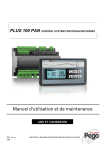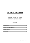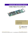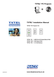
1
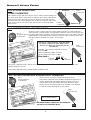
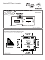
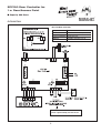
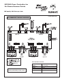
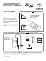
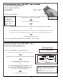
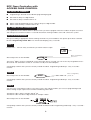
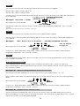
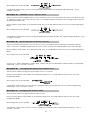
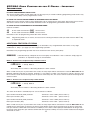
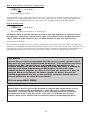
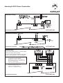
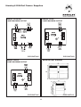
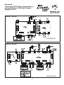
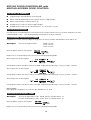
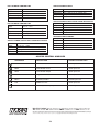
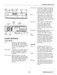
ECP190 / ECP290
DOOR CONTROLLERS
STAND ALONE
ACCESS CONTROL
Site Coded & Sequentially
Numbered Access Passes
for Security, Identification &
Operational Integrity.
®
nacd.co.uk
contents
ECP190
ECP190
/ ECP290
/ ECP290
DOOR
DOORCONTROLLERS
CONTROLLERS
Explanation of Noralsy ® Access Passes
3
General Door Controller Information
4
ECP 190 Door Controller schematic
5
ECP 290 Door Controller schematic
6
How to use the Telpro™ programmer
7-8
Programming
Set-up on installation
9-10
Block loading of Access Passes
10
Deleting individual Access Passes
10-11
Validating individual Access Passes
11
Block deletion of Access Passes
11
Changing lock output time
11
Changing the Master Code
11
ECP290 Additional Features
12-13
Dual Security, Code + Access Pass
13
Fail Safe locking schematic
14
Automation/Volt Free schematic
14
General Locking schematic
15
Din Rail Mounting
15
Din Rail Power Supplies
16
Powering ECP Door Controllers using Din Rail PSU
17
Programming Keypad Codes
18-19
2
NORALSY® ACCESS PASSES
ALL ACCESS PASSES ARE
VISIBLY NUMBERED
Numbered
The number of each and every Access Pass is visible. Just by looking at it,
you know which Access Pass you have. Noralsy® pre-number each Access
Pass because this is the only way you can know for sure what you have
received, what you need to program the system to accept (or, reject in the
case of loss, theft or non-return) and, who has been issued with which
TELBIP
Access Pass.
or TELBIPHF
KCP3
Proximity Key
Numbered
ALL ACCESS PASSES ARE SITE CODED
An Access Pass is always part of a unique group referred to as a Site Code and
represented by a 5 digit number. Your purchase of Noralsy® Access Passes buys you
Rear of
that
group (Site Code) regardless of how many Access Passes you require. That Site
TELBIP/TELBIPHF
Code
belongs to you and you alone. Noralsy® will never make an Access Pass with
or TELBIPHFP
your Site Code for anybody else. That is your security.
Site
Code
The first 3no. digits of the 5no. digit Site Code
are always engraved on each Access Pass.
The last 2no. digits are usually the year of
manufacture.
KCP3
Proximity Key
Example: First 3 digits engraved on Access
Pass are 494.
Year of manufacture 2001, therefore,
last 2n0 digits of site code are 01.
Site Code =
Engraved
on Access Pass
Not
engraved*
Site
Code
The full 5no. digit Site Code is written on the Access Pass Information Sheet supplied by Noralsy® with each
delivery of Access Passes.
*The full 5n0 digit site code is printed on KBP Proximity Cards.
ALL ACCESS PASSES ARE SEQUENTIALLY NUMBERED
Rear of
TELBIP/TELBIPHF
or TELBIPHFP
Holder
Number
Access Passes are always supplied in groups that are
sequentially numbered which simplifies programming because it
enables block loading and block deleting of Access Passes. It
also means that you can quickly and easily determine which
Access Passes are missing and need, therefore, to be deleted
in order to restore the integrity of your system.
KCP3
Proximity Key
Last 3 digits engraved
refer to Holder Number.
The Holder Numbers supplied are also recorded on
the Access Pass Information Sheet.
3
Holder
Number
Noralsy ECP Door Controllers
®
IMPORTANT –If NOT Monitoring Door Open/Closed Status
OR
ECP ALARM
BUZZES CONTINUOUSLY
ELEC/INST/800
6 5 4 3 2 1
ON
6 5 4 3 2 1
1
ECP Door Controller
Standardisation of Terminal Numbering
Place Noralsy unit on a flat surface with PCB facing skywards.
View terminal blocks from the outside looking in. Terminal No. 1
is always the first on the left of every terminal block strip.
1 2 3
1 2 3 4
1 2
1 2 3
1 2 3
1 2
1 2 3 4 5
1 2 3 4 5 6
1 2 3 4
1 2 3
1 2 3
1 2 3 4 5 6
1 2 3
1 2 3 4 5 6 7 8
1 2 3 4 5
1 2 3 4 5 6 7
ELEC/INST/GEN
4
1 2 3 4 5 6
ECP190 Door Controller for
1 n0 Door/Access Point
■ Capacity 999 Users
®
ELEC/INST/801
ECP 190 Door Controller
3 2 1
3 2 1
2 1
(—) (+)
Supply
12V DC ± 10%
Dimensions
103 L x 106 W x 83 D (6 DIN units)
Weight
0.44 Kg
Power Consumption
55mA quiescent
CE Norms
EN50082, EN55022 Class B
3 2 1
2 1
1
5
2
4
3
3
4
2
5
1
1
1 2 3 4 5 6
ON
1 2 3 4 5 6
=
=
1 2 3 4 5 6
If not used, link terminals 3 & 4 to
create a permanently closed circuit.
5
ECP290 Door Controller for
2n0 Doors/Access Points
■ Capacity 999 Users per door
®
ELEC/INST/830
ANTI-PASSBACK FEATURE AVAILABLE
ECP 290 Door Controller
* If not used, link terminals 3 & 4 to
create a permanently closed circuit.
6
Supply
12V DC ± 10%
Dimensions
163 L x 106 W x 83 D (10 DIN units)
Weight
0.56 Kg
Power Consumption
160mA quiescent
CE Norms
EN50082, EN55022 Class B
Programming Stand-Alone
Access Control Systems
using TELPRO™ Programmer.
®
TELPRO™ PROGRAMMER
Access Control Modules with integral Infra-Red
The TELPRO™ Programmer is a handheld
keypad used for programming Noralsy®
stand-alone access control systems.
MLP3
Proximity
The TELPRO™ Programmer
can be used as a wirefree
infra-red programmer. Simply
point at the reader/receiver
module to program.
Installation companies only ever need 1no.
TELPRO™ Programmer.
TELPRO™ can be used on any system
provided, of course, the Master Code (also
referred to as the Engineer Code) which
grants access into programming mode is
known or, access to the ECP Door Controller
itself is available.
The final customer only needs a TELPRO™
unit if they wish to effect programming
themselves.
MIR Infra-Red
TELPRO™
Programmer
Access Control Modules, Readers, Receivers without integral Infra-Red
The TELPRO™
Programmer is
supplied with a
connector cable.
Simply connect to
ECP Door Controller
to program.
LB20 Swipe Card
LTP03
Office Proximity Reader
TELPRO™
Programmer
ECP190
ECP290
ECP100
ECP200
MILB Card Reader
LHF
Dim:
120L x 60W x 25D
Radio receiver
If the entrance or door panel includes a MICAM/MICIM Keypad Module connected to the ECP Door Controller, all
programming can be effected directly via the MICAM/MICIM Keypad ie. TELPRO™ Programmer would not be
required. You would also then have the option of having keypad access codes.
All measurements in millimetres.
7
Programming using TELPRO™ as a remote
wire-free programmer.
Remote Programming Range:
Infra-Red Receiver
Proximity Reader
20 cms - 5 metres
5 cms - 10 cms
How to use the TELPRO:
Important:
Each press of a button
is confirmed (as
received) by the
reader/receiver by a
single beep. Press the
TELPRO™ buttons
gently.
Flick TELPRO switch to ON - Red LED on the right must light up.
(Remember to turn unit off when finished)
Dimensions (mm):
120L x 60W x 25D
Point TELPRO at the reader/receiver.
Enter the Master Code and wait for the reader/receiver to start beeping every 4 seconds
OR
Flick Programming Switch SW1 and wait for the reader/receiver to start beeping every 4 seconds
(Remember to turn off the programming switch SW1 when you have finished programming).
Follow programming instructions
Note: An incorrect programming operation is signalled by a series of 3 beeps.
Programming using TELPRO™ as a
hard-wired programmer
ECP290/ECP200
J5
J6
How to use the TELPRO as a hard wired unit:
= Access Point 1
= Access Point 2
Insert the jack connection into the top of the TELPRO unit.
Plug the connector terminal onto J5 on ECP Door Controller.
Enter the Master Code and wait for the unit
to start beeping every 4 seconds
OR
Flick Programming Switch SW1 and wait for the unit
to start beeping every 4 seconds
(Remember to turn off the programming switch SW1
when you have finished programming)
Follow programming instructions.
8
Important:
Each press of a button is confirmed (as
received) by the Door Controller by a
single beep.
Press the TELPRO™ buttons gently.
ECP Door Controller with
ACCESS PASS CONTROL
PROGRAMMING
TOP POINTS TO REMEMBER
■
Programming is effected via the TELPRO programming keypad.
■
■
Site Code is always a 5 digit number.
Site Code is always stored in Slot No. 01.
■
■
Master Code (Programming Access Code) is always a 5 digit number.
Master Code is always stored in Slot No. 06.
TIP - WHEN YOU ARE PROGRAMMING
It is a good idea to have written down in advance what you want to program. Enter the numbers in quick succession
after a beep. Do not wait more than 2-3 seconds in between entering numbers as this will confuse the system.
SET-UP ON INSTALLATION
Wire up according to appropriate electrical wiring schematic for your installation, then power up the Door Controller.
Flick the Programming Switch SW1. The unit will start beeping every 4 seconds.
STEP 1
Decide Now -- For how many seconds do you want the door to open:
Example
08
After a beep enter on the TELPRO:
000005 08
seconds
Basic configuration,
just do it!
The last 2no. digits, shown as underlined, set the door open time in seconds. You can choose any length between 01 99 seconds. For automation control, 01 seconds is usually more than adequate.
A sharp beep confirms that you have correctly entered the above. Programming mode beep - every 4 seconds resumes.
STEP 2
After a beep enter on the TELPRO:
Basic configuration,
just do it!
02A0
A sharp beep confirms that you have correctly entered the above. Programming mode beep - every 4 seconds resumes.
STEP 3
You must now set the Master Code of your choice. This is the code that allows you to access programming mode
without having to open up the Door Controller and flicking switch SW1.
The Master Code is always stored in Slot No. 06.
The Master Code must be a 5 digit number, for example: 19388.
After a beep enter on the TELPRO:
A sharp beep confirms that you have correctly entered the Master Code. Programming mode beep - every 4 seconds resumes.
9
STEP 4
You must now inform the Door Controller of the Site Code of the Access Passes supplied.
The Site Code is always stored in Slot No. 01.
The Site Code is always a 5 digit number.
Check the Access Pass Information Sheet delivered with the Access Passes. It will tell you the Site Code of the Access
Passes delivered.
*
Example:
Site Code = 45801
After a beep enter on the TELPRO:
A sharp beep confirms that you have correctly entered the Site Code. Programming mode beep - every 4 seconds resumes.
*KBP Proximity Cards have the full site code printed on each card.
STEP 5
You must now inform the Door Controller of the Access Pass Holder Numbers supplied.
Check the Access Pass Information Sheet delivered with the Access Passes. It will tell you which Holder Numbers we
have supplied.
Example:
150no. Access Passes Supplied........HOLDER NUMBERS 001-150.
*See Tip Wizard
on page 13
After a beep enter on the TELPRO:
A series of 3no. beeps followed by a sharper beep confirms that you have correctly entered the Holder Numbers.
Programming mode beep - every 4 seconds - resumes.
STEP 6
Turn off programming switch SW1 in the Door Controller. You have successfully programmed the system. The Access
Passes should now all work.
ADVANCED PROGRAMMING
In the following examples of programming we are assuming that the Master Code = 19388. This is purely for
demonstration purposes. When programming for real, you must enter the Master Code that you chose and set when
the system was installed.
Example A:
Block Loading/Validation of Access Passes.
You have just received an additional 25no. Access Passes for the system. Holder Numbers 151- 175.
Enter the Master Code 19388 on the TELPRO. Beeps every 4 seconds indicate that you have accessed Programming
Mode.
After a beep enter on the TELPRO:
A series of 3no. beeps followed by a sharper beep confirms that you have correctly entered the Holder Numbers.
Programming mode beep - every 4 seconds - resumes.
Example B:
Deletion of 1no. Access Pass
You have just been informed that Alan Jones has lost his Access Pass. Alan was Holder Number 074. You have to
delete it immediately to restore system security. Enter the Master Code 19388 on the TELPRO. Beeps every 4 seconds
indicate that you have accessed Programming Mode.
10
After a beep enter on the TELPRO:
A sharp beep confirms that you have correctly deleted Holder Number 074. Programming mode beep - every 4
seconds - resumes.
Example C:
Validation of 1no. Access Pass
You have just received the additional Access Pass ordered for Alan Jones who had lost his earlier in the week. The last
3no. digits on the Access Pass are 176. Alan Jones is now Holder Number 176 and you have to program the system to
accept Holder Number 176.
Enter the Master Code 19388 on the TELPRO. Beeps every 4 seconds indicate that you have accessed Programming
Mode.
After a beep enter on the TELPRO:
A sharp beep confirms that you have correctly programmed new Holder Number 176. Programming mode beep - every
4 seconds - resumes.
Example D:
Block Deletion of Access Passes
You have just been informed that a set of 20 Access Passes reserved for visitors and held in reception have been
stolen. You have to immediately delete them to restore system security. The Holder Numbers stolen were 080-099.
Enter the Master Code 19388 on the TELPRO. Beeps every 4 seconds indicate that you have accessed Programming
Mode.
After a beep enter on the TELPRO:
A series of 3no. beeps followed by a sharper beep confirms that you have deleted the Holder Numbers. Programming
mode beep - every 4 seconds - resumes.
Example E:
Changing the Relay/Lock Output Time
You have been asked to change the Relay Output Time to 12 seconds.
Enter the current Master Code 19388 on the TELPRO. Beeps every 4 seconds indicate that you have accessed
Programming Mode.
After a beep enter on the TELPRO:
A sharp beep confirms that you have correctly reprogrammed the relay output time for 12 seconds. Programming
mode beep - every 4 seconds - resumes.
Example F:
Changing the Master Code
You have been asked to change the Master Code to 11821.
Enter the current Master Code 19388 on the TELPRO. Beeps every 4 seconds indicate that you have accessed
Programming Mode.
After a beep enter on the TELPRO:
A sharp beep confirms that you have correctly entered the new Master Code. Programming mode beep - every 4
seconds - resumes.
11
ECP290 DOOR CONTROLLER
INFORMATION
FOR
2 DOORS – IMPORTANT
FLICKING PROGRAMMING SWITCH SW1.
The access control readers on both doors will start to beep every 4 seconds indicating programming mode status. Only
1 no. access point (door) can be programmed at a time.
IF USING THE TELPRO PROGRAMMER IN WIREFREE INFRA-RED MODE:
Simply point at the relevant reader to effect programming for its related access point (door). Repeat the process for the
2nd access control reader on the ECP290. Remember to turn off programming switch SW1 when finished.
IF USING TELPRO PROGRAMMER IN HARDWIRED MODE:
Connect as follows:
J5 for the reader connected to I2A1, Access Point 1.
J6
for the reader connected to I2A2, Access Point 2.
Remember to turn off programming switch SW1 when finished.
Note:
Programming mode can, of course, be accessed via entering the Master Code (the code stored in Slot No. 06)
as explained earlier.
ADDITIONAL FEATURES OF ECP290
Activating one of the additional features offered by the ECP290 is very straightforward and involves a very slight
modification of Step 1 (see page 9) of the Programming Operation.
Remember: The programming operation has to be effected for each access point (door).
00000508
= Standard Set-Up, adequate for the vast majority of installations. If this is sufficient, simply copy the
procedure, as explained on page 9, for both doors.
Mode 2 - Access Pass to Operate Only if Vehicle Present
00200500
= Set-Up, Mode 2
È
Alarm delay time in minutes. A 00 setting disables the alarm function.
When a valid access pass is presented to the reader, the relay output will be activated for 2 seconds BUT ONLY IF the
Magnetic Induction Loop (M.I.L) contacts, terminals 1 & 2 of J10A1 or J10A2, have closed ie a vehicle is present. If the
M.I.L contacts remain closed for longer than the preset alarm delay time, the access control reader/receiver/keypad will
sound an alarm.
Mode 3 - Access Pass to Operate Only if Door Closed
00300500
= Set-Up, Mode 3
È
Alarm delay time in minutes. A 00 setting disables the alarm function.
The status of the door is controlled by 2no. sets of contacts as follows:
Open Position Reached (OPR) Contacts:
Door Open Contacts (DO):
Terminals 2 & 3 of J10A1 (Access Point 1)
Terminals 3 & 4 of J9A1 (Access Point 1)
Open Position Reached (OPR) Contacts:
Door Open Contacts (DO):
Terminals 2 & 3 of J10A2 (Access Point 2)
Terminals 3 & 4 of J9A2 (Access Point 2)
When a valid access pass is presented to the reader, the relay output will be activated for 2 seconds BUT ONLY IF the
related Access Point (Door) is closed. If the Access Point (Door) remains open for longer than the preset alarm delay
time (DO Contacts OPEN and OPR Contacts CLOSED) or, if the Access Point (Door) is blocked/stuck for longer than
the preset alarm delay time (DO Contacts OPEN and OPR Contacts OPEN), the access control reader/receiver/keypad
will sound an alarm.
12
Mode 4 - Dual Security, Access Pass + Keypad Code
00400508
= Set-Up, Mode 4
È
Relay output time in seconds
User required to present a valid access pass and then enter a valid code or vice versa in order to gain access. A
maximum of 27no. 5 digit keypad codes can be set at any one time. Any 1no. of these keypad codes together with a
valid access pass is sufficient to gain entry. This feature is also available on the ECP190 Door Controller.
Mode 5 - Anti-Passback
00500508
= Set-Up, Mode 5
È
Relay output time in seconds (this is an example only).
For Anti-Passback to operate, terminals 3 and 4 of J9A1 and J9A2 must be connected to the
Door Contacts fitted to the controlled doors. This is imperative because the Door Controller
cannot operate Anti-Passback if it does not know whether the door was opened or not.
Basic operation is as follows:
The presentation of a valid Access Pass on Door 1 activates the relevant lock release relay. If Door 1 is opened, this
Access Pass is immediately and automatically barred on Door 1 until it has been presented on Door 2 with Door 2 then
being opened. As soon as this Access Pass is presented on Door 2 with Door 2 being opened, it is immediately and
automatically barred on Door 2 until it has been presented on Door 1 with Door 1 then being opened etc etc.
Tip Wizard
Access Passes can be programmed into the access control system even if
they have not yet been manufactured by Noralsy® . Your customer may have
ordered only 50no. Access Passes and would have had delivered, for
example holders 001-050 on their unique Site Code but, there is nothing to
stop you from block programming all 999 holders. It takes the same
amount of time to program 1no. Access Pass into the system as it does to
program 999 Access Passes! So, future supplies of Access Passes are
already programmed into the system and your customer should only ever
have to delete lost or stolen Access Passes!
It is so easy: B001 B999.
VERY IMPORTANT
Noralsy® Access Passes must not be compared or confused with random Access Passesfor example, certain brands of proximity key - where the onus is on the installation
company to “accurately” identify each Access Pass programmed into the system and
physically mark them so that they can be “sure” who is issued with what or, those
systems, which rely on shadow cards or master keys/fobs for programming purposes.
13
Noralsy® ECP Door Controller
®
Fail Safe Locking
+
3 2 1
3 2 1
2 1
(—) (+)
ELEC/INST/802
ECP190 Door Controller
Automation Control / Volt Free
3 2 1
3 2 1
2 1
ELEC/INST/803
ECP190 Door Controller
Entrance/Exit
Access point requiring access control on both
sides of the door, gate or barrier.
ie. Access Pass to be presented to enter and
again to exit through the same control point.
1 2 3 4 5 6
6 5 4 3 2 1
6 5 4 3 2 1
6 5 4 3 2 1
Note: In this type of installation, programming
can take place via the TELPRO
programmer at either one of the Access
Pass readers/receivers or, alternatively, at
the Door Controller itself.
You only need to program at 1no. point.
* Terminal numbering shown for
reasons of schematic clarity.
Terminal 1 is actually first on left.
ECP190 Door Controller
ELEC/INST/804
14
Noralsy® ECP Door Controller
®
Locking
3 2 1
3 2 1
ECP190 Door Controller
2 1
(–) (+)
ELEC/INST/805
DIN Rail Mounting
DIN Rail
ELEC/INST/806
Wall Mounting
ELEC/INST/807
15
Noralsy® DIN Rail Power Supplies
®
ARE121 12V AC/DC
1 AMP MAXIMUM OUTPUT
ARE122 12V DC
2 AMP MAXIMUM OUTPUT
ELEC/INST/808
ELEC/INST/809
ARS122 12V DC
2 AMP MAXIMUM OUTPUT
AB126 BATTERY STANDBY
ELEC/INST/811
ELEC/INST/810
16
Noralsy®
Powering ECP Door Controller(s)
using Noralsy® DIN Rail Power
Supply Units
®
ARE121 + ECP190
ELEC/INST/812
ARE122 + ECP290
ELEC/INST/812A
17
ECP190 DOOR CONTROLLER with
KEYPAD ACCESS CODE CONTROL
TOP POINTS TO REMEMBER
■
Programming is effected directly via the keypad.
■
■
Master Code (Programming Access Code) is always a 5 digit number.
Master Code is always stored in Slot No. 06.
■
■
Keypad Access Codes are always 5 digit numbers.
Keypad Access Codes can be stored in Slot Nos. 03 - 05 and 07 - 30 only.
SET-UP ON INSTALLATION
Proceed exactly as detailed before in section ECP Door Controller with Access Pass Control. Stop when you have
completed Step 3. Then - Turn off programming switch SW1 in the Door Controller.
PROGRAMMING KEYPAD ACCESS CODES
Keypad Access Codes must be 5 digits in length and can only be stored in Slot Numbers 03-05 and 07-30.
Example:
You want to program codes:
46296 for Alan
78327 for Tony
32534 for Alex
Enter the Master Code on the keypad:
Beeps every 4 seconds indicate that you have accessed Programming Mode.
After a beep enter on the keypad:
A sharp beep confirms that Alan’s code is recorded. Programming mode beep - every 4 seconds - resumes.
After a beep enter on the keypad:
A sharp beep confirms that Tony’s code is recorded. Programming mode beep - every 4 seconds - resumes.
After a beep enter on the keypad:
A sharp beep confirms that Alex’s code is recorded. Programming mode beep - every 4 seconds - resumes.
Note Carefully:
Never program a keypad access code into Slot Numbers 01, 02 or 06.
DELETING KEYPAD ACCESS CODES
Example:
You want to delete Alan’s code 46296 which is stored in Slot No. 03
You want to delete Alex’s code 32534 which is stored in Slot No. 07
Enter the Master Code on the keypad:
Beeps every 4 seconds indicate that you have accessed Programming Mode.
18
After a beep enter on the keypad:
A sharp beep confirms that you have deleted Alan’s code. Programming mode beep - every 4 seconds - resumes.
After a beep enter on the keypad:
A sharp beep confirms that you have deleted Alex’s code. Programming mode beep - every 4 seconds - resumes.
Note 1. You do not need to know the actual code itself which needs to be deleted, only the Slot Number in which it is
stored.
Note 2. Capacity is never reduced as a result of deleting codes. You can always add or change codes.
CHANGING THE MASTER CODE
Refer to page 11.
CHANGING RELAY/LOCK OUTPUT TIME
Refer to page 11.
Automatic Time-Out – whenever programming accessed via Master Code
System automatically reverts to normal mode approximately 20 seconds after the last
programming operation. A single longer sharp beep signals that the system has exited
from programming mode and returned to normal mode.
19
ARE122 POWER SUPPLY
ECP 190 DOOR CONTROLLER
Supply
12V DC ±10%
Dimensions
103 L x 106 W x 83 D (6 DIN units)
Input
85VAC - 264VAC
Output
12V DC - 2AMP
Dimensions 160 L x 106 W x 85 D (10 DIN units)
Weight
0.44 Kg
Power Consumption
55mA quiescent
CE Norms
EN50082, EN55022 Class B
Weight
0.5 Kg
CE Norms
EN55022 Class B, EN 60950, UL 94 VO
ARS122 POWER SUPPLY WITH STAND-BY FACILITY
ECP 290 DOOR CONTROLLER
Input
85VAC - 264VAC
Output
12V DC - 2AMP
Supply
12V DC ± 10%
Dimensions 160 L x 106 W x 85 D (10 DIN units)
Dimensions
163 L x 106 W x 83 D (10 DIN units)
Weight
0.5 Kg
Weight
0.56 Kg
CE Norms
EN55022 Class B, EN 60950, UL 94 VO
Power Consumption
160mA quiescent
CE Norms
EN50082, EN55022 Class B
AB126 BATTERY STANDBY
Battery
12V/6A.H.
ARE121 POWER SUPPLY WITH STAND-BY FACILITY
Output
12V DC - 2AMP
Input
85VAC - 264VAC
Dimensions 162 L x 106 W x 112 D (10 DIN units)
Output
12V AC/DC - 1AMP
Weight
3.0 Kg
CE Norms
VDS, IEC 1056
Dimensions 135 L x 106 W x 85 D (8 DIN units)
Weight
1.05 Kg
CE Norms
EN50082, EN55022 Class B
ACCESS CONTROL MODULES
REFERENCE
DESCRIPTION
POWER CONSUMPTION
MIR
Infra-Red Receiver
25mA quiescent
MILB
Card Reader Insert
47mA quiescent
LB20
Card Reader Swipe
30mA quiescent
MICAM/MICIM
Keypad
50mA quiescent
MLP3
Proximity Reader
120mA quiescent
LHF
Radio Receiver
25mA quiescent
LPT03
Proximity Reader (office)
120mA quiescent
N.A.C.D. Limited
Unit 10, Avebury Court, Mark Road, Hemel Hempstead, Herts HP2 7TA.
TEL: 01442 211848 FAX: 01442 212776 EMAIL: [email protected] WEB: www.nacd.co.uk
Our policy is one of continuous product improvement, we reserve the right to change specifications and prices without notice. All information is given in good
faith. No responsibility can be accepted for errors, omissions or incorrect assumptions. Picture reproduction of products are within the limitations of both colour
and black and white printing and are intended as a guide only. © Copyright 2001 N.A.C.D. Limited. All rights reserved.
20