1
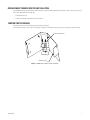
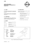
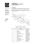
I N S T A L L A T I O N
HS2000
High Security
Enclosure
C494M-E (9/06)
Contents
Important Safety Instructions . . . . . . . . . . . . . . . . . . . . . . . . . . . . . . . . . . . . . . . . . . . . . . . . . . . . . . . . . . . . . . . . . . . . . . . . . . . . . . . . . . . . . . . . . . . .4
Description . . . . . . . . . . . . . . . . . . . . . . . . . . . . . . . . . . . . . . . . . . . . . . . . . . . . . . . . . . . . . . . . . . . . . . . . . . . . . . . . . . . . . . . . . . . . . . . . . . . . . . . . . .5
Option . . . . . . . . . . . . . . . . . . . . . . . . . . . . . . . . . . . . . . . . . . . . . . . . . . . . . . . . . . . . . . . . . . . . . . . . . . . . . . . . . . . . . . . . . . . . . . . . . . . . . . . . . .5
Installation . . . . . . . . . . . . . . . . . . . . . . . . . . . . . . . . . . . . . . . . . . . . . . . . . . . . . . . . . . . . . . . . . . . . . . . . . . . . . . . . . . . . . . . . . . . . . . . . . . . . . . . . . .6
Optional Window Installation . . . . . . . . . . . . . . . . . . . . . . . . . . . . . . . . . . . . . . . . . . . . . . . . . . . . . . . . . . . . . . . . . . . . . . . . . . . . . . . . . . . . . . .6
Replacement Tamper Switch Installation . . . . . . . . . . . . . . . . . . . . . . . . . . . . . . . . . . . . . . . . . . . . . . . . . . . . . . . . . . . . . . . . . . . . . . . . . . . . . .7
Tamper Switch Wiring . . . . . . . . . . . . . . . . . . . . . . . . . . . . . . . . . . . . . . . . . . . . . . . . . . . . . . . . . . . . . . . . . . . . . . . . . . . . . . . . . . . . . . . . . . . . .7
Maintenance . . . . . . . . . . . . . . . . . . . . . . . . . . . . . . . . . . . . . . . . . . . . . . . . . . . . . . . . . . . . . . . . . . . . . . . . . . . . . . . . . . . . . . . . . . . . . . . . . . . . . . . . .8
Service Manual . . . . . . . . . . . . . . . . . . . . . . . . . . . . . . . . . . . . . . . . . . . . . . . . . . . . . . . . . . . . . . . . . . . . . . . . . . . . . . . . . . . . . . . . . . . . . . . . . .8
Exploded Assembly Diagram . . . . . . . . . . . . . . . . . . . . . . . . . . . . . . . . . . . . . . . . . . . . . . . . . . . . . . . . . . . . . . . . . . . . . . . . . . . . . . . . . . . . . . . . . . . .9
Specifications . . . . . . . . . . . . . . . . . . . . . . . . . . . . . . . . . . . . . . . . . . . . . . . . . . . . . . . . . . . . . . . . . . . . . . . . . . . . . . . . . . . . . . . . . . . . . . . . . . . . . . .10
C494M-E (9/06)
3
Important Safety Instructions
1. Installation and servicing should be done only by qualified service personnel and conform to all local codes.
2. Unless the unit is specifically marked as a NEMA Type 3, 3R, 3S, 4, 4X, 6, or 6P enclosure, it is designed for indoor use only and it must not
be installed where exposed to rain and moisture.
3. Only use replacement parts recommended by Pelco.
4. The camera and lens combination shall not exceed 20 lb (9.06 kg).
5. The installation method and materials should be capable of supporting four times the weight of the enclosure, pan/tilt, and camera and
lens combination.
The product may bear the following marks:
This symbol indicates that dangerous voltage constituting a risk of
electric shock is present within this unit.
This symbol indicates that there are important operating and
maintenance instructions in the literature accompanying this unit.
4
CAUTION:
RISK OF ELECTRIC SHOCK.
DO NOT OPEN.
C494M-E (9/06)
Description
The HS2000 high-security camera enclosure is designed for indoor corner mount installation in such settings as elevators, parking garages,
classrooms, offices, and detention cells requiring maximum protection from vandalism in an unobtrusive package. It fits flush to the ceiling in a
corner. An impact-resistant clear Lexan® polycarbonate resin thermoplastic window is supplied, and an optional smoked window is available.
Constructed of medium gauge steel, the HS2000 will accept many of the smaller CCD cameras with fixed focal length and auto-iris lenses. There
is no exposed mounting hardware securing the HS2000 to its mounting surface. Opening the enclosure can only be accomplished by removing
the tamper-resistant screw from the bottom. For additional security, a factory-installed tamper switch is mounted on the secured access cover.
OPTIONAL ACCESSORY
HS200010019
C494M-E (9/06)
Smoked window, 0.25" (6.35 mm) thick, impact and abrasion-resistant Lexan polycarbonate resin thermoplastic
5
Installation
Before installing the HS2000 to a wall, make sure that the mounting surface is able to support four times the full weight of the enclosure,
camera, and lens.
The tilt table and tilt table mounting brackets may be removed to provide adequate clearance for mounting the enclosure.
NOTE: The four fasteners required to secure the HS2000 to a wall (minimum 3/8” diameter recommended) are not supplied.
To mount the enclosure to a wall (tight to the ceiling), perform the following steps:
1. Remove the cover from the mounting bracket. A special socket is provided (fits 1/4" square drive).
2. Using the mounting bracket as a template, mark and drill holes in the mounting surface.
3. Attach the enclosure with the required fasteners.
4. Route the required cables through the back or top.
5. Mount the camera/lens to the tilt table.
6. Make all appropriate connections: camera power, video [coax], and lens.
7. Position the camera and tighten the 1/4-20 fasteners to secure the tilt table in place.
8. Replace the cover and secure with the 1/4-20 tamper-resistant screw that is provided.
NOTE: A plate is provided to prevent access through the top of this enclosure. If needed, it is mounted with the mounting bracket using the
same mounting holes and hardware.
OPTIONAL WINDOW INSTALLATION
The HS2000 is provided with a clear 0.25" (6.35 mm) thick viewing window. An optional smoked window, HS200010019, is available.
Instructions for installing the optional smoked window are as follows:
1. Remove the cover from the mounting bracket. A special socket is provided.
2. Remove the four 1/4-20 elastic locknuts and 1/4" flat washers.
3. Remove the window.
4. Remove the protective coatings from the new window and place the window over the four 1/4-20 studs.
5. Replace the hardware and replace the cover.
6
C494M-E (9/06)
REPLACEMENT TAMPER SWITCH INSTALLATION
The HS2000 enclosure comes with a tamper switch installed. If you need to install a replacement switch, refer to Figure 1 for the correct position
of the switch and perform the following steps:
1. Remove the front cover.
2. Install the switch and secure with lock washers and nuts.
TAMPER SWITCH WIRING
The tamper switch comes with normally open and normally closed contacts.
For a normally open circuit, use the “open” and “common” terminals; for a normally closed circuit, use the “closed” and “common” terminals.
BRACKET/SWITCH
MOUNTING PLATE
Figure 1. HS2000 Series Tamper Switch Installation
C494M-E (9/06)
7
Maintenance
Maintenance performed at regularly scheduled intervals will help prolong the operational life and appearance of the equipment.
Clean the window with a mild nonabrasive detergent in water and a soft cloth regularly to help maintain picture clarity. For a heavily soiled
window, use vinyl cleaner.
SERVICE MANUAL
If you need to repair the camera enclosure, obtain a service manual in one of the following ways:
8
•
Go to Pelco’s we site at www.pelco.com and find service manual C494SM.
•
Contact Pelco’s Literature Department and request service manual C494SM.
C494M-E (9/06)
Exploded Assembly Diagram
Figure 2. HS2000 Exploded Assembly Diagram
Table A. Mechanical Parts List
Item No.
A
B
C
D
E
F
G
H
I
J
C494M-E (9/06)
Qty
1
1
1
1
1
1
1
1
1
2
1
2
2
4
11
4
1
2
2
Description
Bracket, switch, break-in
Window, 8" x 7" x 0.25" drilled MR10 clear Lexan thermoplastic
Plate, mounting
Cover, front, beige
Tilt table
Cover, top, corner mount
Bracket, mount, tilt table, left
Bracket, mount, tilt table, right
Switch, tamper
Screw, 1/4-20 x 1/2", round, tamper-resistant, #10, stainless steel
Screw, 1/4-20 x 3/4", round, tamper-resistant, #10, stainless steel
Bolt, 1/4-20 x 5/8", hex cap head, stainless steel
Nut, hex, 1/4-20, stainless steel
Washer, split lock, 1/4", stainless steel
Washer, flat, 3/16", special, stainless steel
Nut, lock, 1/4-20 nylon insert, stainless steel
Socket, tamper-resistant #10, 1/4" drive (not shown)
Nut, hex, 6-32, stainless steel
Washer, lock, internal tooth, #6, stainless steel
Part Number
HS10004313COMP
MF00-0250-001A
HS20004001COMP
HS20004003COMP
HS20004007COMP
HS20004023COMP
HS20004115COMP
HS20004215COMP
SWI1DM401
ZH1/4-20X.50SRT
ZH1/4-20X.75SRT
ZH1/420X.625CH
ZH1/4-20NUTCH
ZH1/4LWSSL
ZH260X562X65C
ZH1/420NUTCHN
ZTSOCKET10
ZH6-32NUTSH
ZH6LWSIS
9
Specifications
Mechanical
Camera Mounting
Adjustable tilt table
Maximum Camera/Lens Size
Accepts camera/lens combinations (including BNC connector) up to
3.0" H x 3.0" W x 6.0" L (7.62 x 7.62 x 15.24 cm)
Enclosure Mounting
Four 0.390-inch (0.99 cm) diameter holes on protected rear surface
Security
Tamper-resistant screw; N.O./N.C. switch contact on cover
Tamper Switch
Plunger type door switch with “pull to cheat” feature. N.O./N.C. contacts clearly marked on body of
switch. DM electrical rating: 10 A, 125 VAC.
Electrical
Cable Entry
Access through back and top
Tamper Switch
0.250-inch (0.63 cm) quick connect. N.O./N.C. clearly marked on switch body. 10 A maximum switching
current, 125 VAC maximum switching voltage
General
Window
0.250-inch (6.35 mm) thick impact and abrasion-resistant, clear Lexan polycarbonate resin thermoplastic
Construction
Formed 14 gauge 0.074-inch (0.19 cm) steel
Finish
Gray polyester powdercoat
Environment
Indoor; 32° to 120°F (0° to 49°C)
Unit Weight
7.77 lb (3.52 kg)
(Design and product specifications are subject to change without notice.)
10.25
(26.04)
4.50
(11.43)
5.00
(12.70)
10.13
(25.73)
8.00
(20.23)
NOTE: VALUES IN PARENTHESES ARE CENTIMETERS; ALL OTHERS ARE INCHES.
10
C494M-E (9/06)
PRODUCT WARRANTY AND RETURN INFORMATION
WARRANTY
Pelco will repair or replace, without charge, any merchandise proved defective in material or
workmanship for a period of one year after the date of shipment.
Exceptions to this warranty are as noted below:
• Five years on FR/FT/FS Series fiber optic products and TW3000 Series unshielded twisted
pair transmission products.
• Three years on Genex ® Series products (multiplexers, server, and keyboard).
• Three years on Camclosure ® and fixed camera models, except the CC3701H-2,
CC3701H-2X, CC3751H-2, CC3651H-2X, MC3651H-2, and MC3651H-2X camera models,
which have a five-year warranty.
• Three years on PMCL200/300/400 Series LCD monitors.
• Two years on standard motorized or fixed focal length lenses.
• Two years on Legacy ®, CM6700/CM6800/CM9700 Series matrix, and DF5/DF8 Series
fixed dome products.
®
®
™
• Two years on Spectra , Esprit , ExSite , and PS20 scanners, including when used in
continuous motion applications.
• Two years on Esprit ® and WW5700 Series window wiper (excluding wiper blades).
• Two years (except lamp and color wheel) on Digital Light Processing (DLP ®) displays.
The lamp and color wheel will be covered for a period of 90 days. The air filter is not
covered under warranty.
• Eighteen months on DX Series digital video recorders, NVR300 Series network video
recorders, and Endura ™ Series distributed network-based video products.
• One year (except video heads) on video cassette recorders (VCRs). Video heads will be
covered for a period of six months.
• Six months on all pan and tilts, scanners or preset lenses used in continuous motion
applications (that is, preset scan, tour and auto scan modes).
Pelco will warrant all replacement parts and repairs for 90 days from the date of Pelco
shipment. All goods requiring warranty repair shall be sent freight prepaid to Pelco, Clovis,
California. Repairs made necessary by reason of misuse, alteration, normal wear, or accident
are not covered under this warranty.
Pelco assumes no risk and shall be subject to no liability for damages or loss resulting from
the specific use or application made of the Products. Pelco’s liability for any claim, whether
based on breach of contract, negligence, infringement of any rights of any party or product
liability, relating to the Products shall not exceed the price paid by the Dealer to Pelco for
such Products. In no event will Pelco be liable for any special, incidental or consequential
damages (including loss of use, loss of profit and claims of third parties) however caused,
whether by the negligence of Pelco or otherwise.
The above warranty provides the Dealer with specific legal rights. The Dealer may also have
additional rights, which are subject to variation from state to state.
If a warranty repair is required, the Dealer must contact Pelco at (800) 289-9100 or
(559) 292-1981 to obtain a Repair Authorization number (RA), and provide the following
information:
1. Model and serial number
2. Date of shipment, P.O. number, Sales Order number, or Pelco invoice number
3. Details of the defect or problem
If there is a dispute regarding the warranty of a product which does not fall under the
warranty conditions stated above, please include a written explanation with the product
when returned.
Method of return shipment shall be the same or equal to the method by which the item was
received by Pelco.
RETURNS
In order to expedite parts returned to the factory for repair or credit, please call the factory at
(800) 289-9100 or (559) 292-1981 to obtain an authorization number (CA number if returned
for credit, and RA number if returned for repair).
All merchandise returned for credit may be subject to a 20% restocking and refurbishing
charge.
Goods returned for repair or credit should be clearly identified with the assigned CA or RA
number and freight should be prepaid. Ship to the appropriate address below.
If you are located within the continental U.S., Alaska, Hawaii or Puerto Rico, send goods to:
Service Department
Pelco
3500 Pelco Way
Clovis, CA 93612-5699
If you are located outside the continental U.S., Alaska, Hawaii or Puerto Rico and are
instructed to return goods to the USA, you may do one of the following:
If the goods are to be sent by a COURIER SERVICE, send the goods to:
Pelco
3500 Pelco Way
Clovis, CA 93612-5699 USA
If the goods are to be sent by a FREIGHT FORWARDER, send the goods to:
Pelco c/o Expeditors
473 Eccles Avenue
South San Francisco, CA 94080 USA
Phone: 650-737-1700
Fax: 650-737-0933
The materials used in the manufacture of this document and its components are compliant to the requirements of Directive 2002/95/EC.
This equipment contains electrical or electronic components that must be recycled properly to comply with Directive 2002/96/EC of the European Union
regarding the disposal of waste electrical and electronic equipment (WEEE). Contact your local dealer for procedures for recycling this equipment.
REVISION HISTORY
Manual #
C494M
C494M-A
C494M-B
C494M-C
C494M-D
C494M-E
Date
5/90
9/93
9/95
11/95
1/96
4/96
9/06
Comments
Original version.
Put into two-column format. Exploded assembly diagram and parts list updated.
Rev. B. Revised to include wiring instructions for tamper switch and put into new two-column format.
Rev. C. Revised to include updated tamper switch/bracket part numbers and exploded view diagram.
Rev. D. Revised to include tamper switch installation, specification description and new part numbers per ECO 95-397.
Revised Section 7.0, item no. 1 to part number HS10004313COMP.
Updated to new format. Revised per ECO 05-13392. Removed obsolete models. Updated parts list per ECO 06-14885 and 06-13896.
Pelco, the Pelco logo, Camclosure, Esprit, Genex, Legacy, and Spectra are registered trademarks of Pelco.
Endura and ExSite are trademarks of Pelco.
DLP is a registered trademark of Texas Instruments, Inc.
Lexan is a registered trademark of the General Electric Company.
©Copyright 2006, Pelco. All rights reserved.
Worldwide Headquarters
3500 Pelco Way
Clovis, California 93612 USA
USA & Canada
Tel: 800/289-9100
Fax: 800/289-9150
International
Tel: 1-559/292-1981
Fax: 1-559/348-1120
www.pelco.com
ISO9001
Australia
| Canada | Finland | France | Italy | Russia | Singapore | Spain | Sweden | The Netherlands | United Arab Emirates | United Kingdom | United States