1
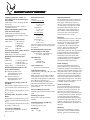
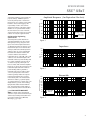
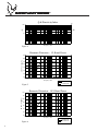
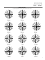
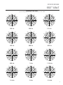
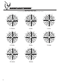
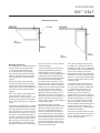
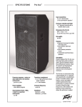
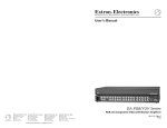
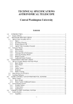
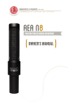
SPECIFICATIONS
SSE™ UB2T
Under Balcony Array
Description
Designed for permanent professional
installation in schools, churches, theaters,
auditoriums, gyms, night clubs, offices and
theme parks, the SSE UB2T is a quarterspherical coverage array providing mid/
high frequency coverage of an entire small
room, or under a balcony or other barrier
spot/delay coverage.
Constructed of premium plywood for
strength, rigidity and light weight, the SSE
UB2T has a perforated metal grille covered
with cloth for a subtle appearance. Builtin hanging points provide stability and
flexibility in coverage adjustment.
This mid/high frequency quarter-spherical
array is comprised of four 2” neodymium
speakers, with wide dispersion and a very
smooth response across their operating
band. When mated with a companion
woofer module, this combination provides
a clear, smooth full-range sound from a
hung system. Input to the array is via
barrier strip screw terminals. A built-in
70V/100V transformer with switchselectable taps and an 8-ohm input
option provide maximum flexibility for
installations. A separately available
active crossover with equalization assures
smooth, even frequency response across
the operating band.
• 180º by 90º pattern covers a small room or
space
• Designed for placement at the ceiling/
wall junction or under-balcony locations
• Whole-room mid/high frequency
coverage from one enclosure
• Small size makes it unobtrusive
• Processor-based crossover and EQ for
maximum performance
• Hanging points incorporated
• Available in black and white painted
finishes
Features
• Uniquely angled speakers provide wide,
even response
• Dual-orientation design for more defined
coverage
• Built-in 70V/100V transformer
• Switch selected taps at 30W, 15W, 7.5W,
3.7W, 1.8W and 8 ohms
Frequency Response, 1 meter onaxis, swept-sine in one-fourth space
environment:
8 Ohm Input: 160 Hz to 16 kHz (±3 dB with
processing)
Transformer Input: 200 Hz to 16 kHz (+/3 dB with processing)
Usable Low Frequency Limit (-10 dB
point one fourth space):
8 Ohm Input: 110 Hz (with processing)
Transformer Input: 180 Hz (with processing
and crossover)
Power Handling (above 200 Hz):
8 Ohm Input:
Transformer
Input:
50W continuous
100W program
200W peak
30W continuous
60W peak
Sound Pressure Level, 1 watt, 1 meter in
anechoic environment:
8 Ohm Input: 90 dB SPL, (2.83 V input)
Maximum Sound Pressure Level
(1meter):
8 Ohm Input:
Transformer
Input, 30W tap:
107 dB SPL continuous
113 dB SPL peak
103 dB SPL continuous
106 dB SPL peak
Radiation Angle measured at -6 dB
point of polar response:
Operating Into Quarter Space:
Horizontal Dispersion: 180º
Vertical Dispersion: 90º
Operating Into Half Space:
Horizontal Dispersion: 180º
Vertical Dispersion: 110º
Directivity Factor, Ro (Q), 500 Hz – 16
kHz Mean:
Unit has textbook-perfect dispersion of Q =
4 for one-fourth space environment (180º X
90º )
For one-half space environment (180º X 180º),
Q= 3.1 +1.0/-1.1
Harmonic Distortion:
Frequency Response
8 Ohm In:
1% rated power (or 1W)
2nd Harmonic:
200 Hz: 0.51%
1 kHz:0.1%
3rd Harmonic:
200 Hz: .42%
1 kHz: 0.1%
10% rated power
2nd Harmonic:
200 Hz: 0.91%
1 kHz: 0.1%
3rd Harmonic:
200 Hz: 2.12%
1 kHz: 0.32%
Transformer Input: Less than 3% up to rated
power of 30W and above 200 Hz, typically
less than 1%.
This measurement is useful in determining
how accurately a given unit reproduces an
input signal. The frequency response of
the SSE™ UB2T is measured at a distance
of 1 meter using a 1 watt (into the nominal
impedance) swept-sine input signal. As
shown in figure 1, the selected drivers in
the SSE UB2T combine with the signal
processing to give a smooth frequency
response from 160 Hz to 16 kHz .
Recommended Active Crossover
Frequency Region and Slope:
Low Frequency - High Frequency:
200 Hz at 24 dB/octave
Impedance (Z):
8 Ohm Input:
Nominal: 8W
Minimum: 7.2W
Input Connections:
Barrier strip screw terminals
Input Selection Switch:
Selects between 30W, 15W, 7.5W, 3.7W, 1.8W
or 8 Ohms Input
NOTE: 30W tap is for 70V input use ONLY!
100V input uses next tap down, e.g., with
100V input, use the 15W tap for 30W output,
the 7.5W tap for 15W output, etc.
Use of the nominally 70V 30W tap on 100V
will exceed the transformer and system
power rating, and will result in failure of the
speaker system.
Enclosure Materials & Finish:
Premium plywood finished in black or white
paint
Directivity Index, Di 500 Hz – 16 kHz
Mean:
Mounting Provisions:
Unit has textbook-perfect dispersion of Di =
6 dB for one-fourth space environment (180º
X 90º )
For one-half space environment (180º X 180º),
Di=4.8 dB, +1.2dB/-1.8 dB
Overall Dimensions (H x W x D):
Transducer Complement:
Four wide-band neodymium 2” speakers
with 1” voice coil
2
Flying point for suspension, bracket
included.
3.23" x 13.78" x 6.12"
82 mm x 350 mm x 155 mm
Net Weight:
5 lbs.
(2.3 kg)
Directivity
Beamwidth is derived from the -6 dB points
from the polar plots (see figure 3) which
are measured in a whole-space anechoic
environment. Q and Directivity Index
are plotted for the on-axis measurement
position. These are specifications that
provide a reference to the coverage
characteristics of the unit. These parameters
provide insight for proper placement and
installation in the chosen environment.
The blending of the components of the
SSE UB2T exhibits a desirable beamwidth
and directivity (figure 3 & 4) suitable for
permanent installation applications.
Power Handling
There are many different approaches to
power handling ratings. Peavey rates this
loudspeaker system’s power handling using
a full-range form of the AES Standard 2-1984.
Using audio band 20 Hz to 20 kHz pink noise
with peaks of four times the RMS level, this
strenuous test signal assures the user that
every portion of this system can withstand
today’s high technology music. This rating is
contingent upon having a minimum of 3 dB
of amplifier headroom available.
Harmonic Distortion
Second and third harmonic distortions vs.
frequency for the 8-ohm input are plotted
in figures 5 & 6 for two power levels. Ten
percent (10%) of rated input power and
either one percent (1%) of rated input power
or one watt, whichever is greater. Distortion
is read from the graph as the difference
between the fundamental signal (frequency
response) and the desired harmonic. As an
example, a distortion curve that is down 40
dB from the fundamental is equivalent to 1%
distortion.
Mounting
Caution: Before attempting to suspend
this speaker, consult a certified structural
engineer. Speaker can fall if improperly
SPECIFICATIONS
SSE™ UB2T
110
Architectural & Engineering
Specifications
3 + 2 YEAR LIMITED WARRANTY
NOTE: For details, refer to the warranty
statement. Copies of this statement may be
obtained by contacting Peavey Electronics
Corporation, P.O. Box 2898, Meridian,
Mississippi, 39301-2898.
90
80
HF Only vs System
SSE- UB2
W/ woofer
70
60
20
50
100
200
Figure 1
500
1k
Frequency (Hz)
2k
5k
10k
20k
2k
5k
10k
20k
2k
5k
10k
20k
Impedance
100
50
30
20
Z
( ) 10
5
3
2
1
20
50
100
200
Figure 2
500
1k
Frequency (Hz)
Beamwidth
360
300
Beamwidth (Degrees)
The loudspeaker system shall have an
operating bandwidth of 160 Hz to 16 kHz
with signal processing, using the 8 ohm
input. The nominal output level shall be
90 dB when measured at a distance of one
meter with an input of one watt into the 8
ohm input, where the nominal impedance
shall be 8 ohms. A 70V/100V distributed
line transformer shall be included, with
a selector switch to select between
transformer taps of: 30W, 15W, 7.5W, 3.7W,
1.8W or to an 8 ohm nominal input. The
maximum continuous power handling shall
be 50 watts, maximum program power of
100 watts and a peak power input of at
least 200 watts, with a minimum amplifier
headroom of 3 dB, for the 8 ohm input. The
transformer input maximum continuous
power handling shall be 30W, with a
maximum peak power of 60W, for either
a 100V or 70V input line. The nominal
radiation geometry shall be 180 degrees
in the horizontal plane and 90 degrees
in the vertical plane. The overall outside
dimensions shall be 3.23 inches high by
13.78 inches wide by 6.12 inches deep. The
weight shall be 5 pounds. The mounting/
flying bracket shall be included with the
unit. The loudspeaker system shall be a
Peavey Sanctuary Series model SSE UB2T.
Amplitude Response (1m Equivalent On-Axis)
100
dB SPL (re 20 Pa)
suspended, resulting in serious injury and
property damage. DO NOT suspend or
mount any other product or device from
this enclosure. Use only the correct mating
hardware. All associated rigging is the
responsibility of others. This unit was
designed to be hung on the wall or ceiling
with the use of a special bracket that fits
into the enclosure, via a slot on the rear,
and an insert located on the top rear of the
cabinet. Use only the supplied bracket.
180
140
100
80
60
40
30
20
Figure 3
Horizontal
Vertical
50
100
200
500
1k
Frequency (Hz)
3
Q & Directivity Index
100
20
Q
Di
10
10
1
20
50
100
200
Figure 4
110
500
1k
Frequency (Hz)
2k
5k
10k
0
20k
Harmonic Distortion : 1% Rated Power
dB SPL (re 20 Pa)
100
90
80
70
60
50
40
20
50
100
200
500
1k
Frequency (Hz)
2k
10k
20k
2nd Harmonic
3rd Harmonic
Figure 5
120
5k
Harmonic Distortion : 10% Rated Power
110
dB SPL (re 20 Pa)
100
90
80
70
60
50
20
Figure 6
4
50
100
200
500
1k
Frequency (Hz)
2k
5k
10k
2nd Harmonic
3rd Harmonic
20k
SPECIFICATIONS
SSE™ UB2T
Vertical Polar Plots
1/3 octave averaged plotted on ISO 1/3 octave centers from 200 Hz - 16 kHz.
o
o
o
90
90
o
60
30
60
90
o
o
30
o
o
o
-30
o
-90
o
-60
-90
200 Hz
-30
-90
-60
90
o
o
o
-30
30
o
90
-90
o
90
o
60
30
o
0
o
-30
-30
o
-90
o
-90
30
-60
o
90
o
60
o
30
o
60
o
o
30
o
o
0
0
-30
o
1.25 kHz
o
90
o
o
o
-60
1 kHz
o
o
o
o
800 Hz
1.6 kHz
30
0
o
-60
o
60
o
o
o
-60
o
630 Hz
o
-60
o
0
o
-30
o
-30
o
-90
o
2 kHz
o
o
-60
0
-90
-30
o
60
o
o
500 Hz
-30
o
0
o
o
o
o
o
30
90
60
0
-90
60
o
60
o
o
o
-60
o
o
315 Hz
30
400 Hz
-90
-30
o
o
0
90
o
o
90
o
30
o
-60
o
0
o
60
-90
o
o
o
250 Hz
o
90
30
0
0
-30
o
60
o
o
o
-60
-90
o
-60
2.5 kHz
5
Vertical Polar Plots
1/3 octave averaged plotted on ISO 1/3 octave centers from 200 Hz - 16 kHz.
o
o
o
90
90
o
30
90
o
o
30
o
o
o
-30
-60
-90
3.15 kHz
60
90
o
30
o
-60
-90
90
o
o
30
-30
o
o
90
o
o
-60
-90
o
60
o
30
o
o
o
0
0
o
o
-30
-30
o
o
12.5 kHz
6
-60
-90
o
16 kHz
o
10 kHz
o
60
o
-30
8 kHz
30
-90
o
0
o
-90
o
o
o
o
90
o
0
o
6.3 kHz
o
60
60
30
-60
-60
o
o
o
o
o
o
5 kHz
0
-90
-30
o
o
-30
o
0
o
4 kHz
o
90
o
0
o
-90
30
o
o
0
-30
o
60
60
60
-60
-60
o
SPECIFICATIONS
SSE™ UB2T
Horizontal Polar Plots
1/3 octave averaged plotted on ISO 1/3 octave centers from 200 Hz - 16 kHz.
o
30
o
0
-30
o
o
60
90
30
-60
-90
o
0
-30
o
90
90
-30
o
o
90
o
-30
-30
o
o
90
30
o
o
60
o
90
o
o
90
-60
o
o
-90
o
o
-30
o
o
30
0
o
o
-90
2 kHz
-30
1.25 kHz
-60
o
o
o
o
o
o
o
-90
0
0
60
-90
o
o
-90
o
o
30
o
o
-60
o
90
o
-30
o
1 kHz
-60
1.6 kHz
0
o
60
o
-60
o
o
0
60
800 Hz
o
-90
630 Hz
o
o
-90
60
o
30
-90
30
-60
0
90
o
o
o
o
o
o
o
o
-30
-60
o
o
-60
o
60
o
-30
60
500 Hz
60
30
0
o
315 Hz
o
o
-90
o
400 Hz
90
0
o
o
o
-90
30
o
0
30
o
o
-60
o
o
-60
o
o
30
-30
250 Hz
60
90
o
60
200 Hz
30
0
o
o
o
o
60
o
-30
o
-60
o
90
o
-90
o
2.5 kHz
7
Horizontal Polar Plots
1/3 octave averaged plotted on ISO 1/3 octave centers from 200 Hz - 16 kHz.
o
30
60
o
0
o
o
30
-30
o
-60
o
-90
o
0
o
90
-30
o
o
30
-90
90
60
0
o
8
-30
30
o
60
o
90
o
0
60
o
-30
o
o
-90
16 kHz
o
o
o
-30
o
-60
o
90
o
-90
10 kHz
-60
o
0
o
o
o
o
o
-90
o
-90
o
-90
12.5 kHz
o
30
8 kHz
-60
90
-60
90
o
o
o
o
o
-30
-60
6.3 kHz
o
-30
60
o
60
o
o
5 kHz
o
o
o
0
0
o
o
-90
o
-60
o
30
-60
o
o
30
o
o
4 kHz
60
90
-30
60
3.15 kHz
30
o
o
o
90
0
o
SPECIFICATIONS
SSE™ UB2T
Mounting Instructions:
Mounting Instructions:
As a helpful guide to assembling the bracket
onto the cabinet for hanging the cabinet
on a wall, the following assembly steps
are one example of the steps you might
take to prepare the bracket and attach the
cabinet to a drywall-covered 2x4 stud wall,
after consulting with a certified structural
engineer.
Remove the bracket from the cabinet by
unscrewing the shallow-head bolt from the
nominal bottom of the cabinet (small side),
noting how the bracket is mated with the slot
in the cabinet and saving all the hardware
supplied.
Now is a good time to set the input selector
to the proper input. Select one of the
transformer taps, or the 8 ohm input, since it
would otherwise require that the cabinet be
dis-mounted from the bracket to change the
setting.
Decide where the unit will hang and in which
orientation (See Figures A and B). Note that
the supplied bracket can have the mounting
bolt go through the rear of the bracket or the
end opposite of the cabinet slot, so there are
two options to allow maximum flexibility in
mounting to the ceiling or the wall. With the
help of a certified structural engineer, find a
wall, ceiling stud or other suitable location
and select which hole on the bracket will
best interface with that spot. Both mounting
holes can be used in a corner for maximum
safety and reliability.
Locate the mounting hole on the selected
spot by placing the bracket against the
ceiling/wall in the desired pre-selected
location. Mark this location by lightly driving
a small nail into the wall surface through
the correct bracket hole (centered) and then
removing the nail. Pre-drill the fastener
hole with the proper size drill bit to allow
the fastener shaft to enter the stud without
splitting it, but not so large as to allow the
threads to strip out. Next install the bracket
onto the ceiling/wall in the orientation
selected, being sure to install it using the
appropriate fastener (nominally a 1/4” x 3”
lag bolt) into an inner wall or ceiling stud.
Never drive a lag bolt into just drywall or just
paneling as this will not hold the cabinet
safely. Consult a certified structural engineer
for all mounting details.
The wall fastener will go through the
appropriate bracket hole with a lock washer
between it and the bracket. Tighten down
this fastener making sure the bracket is
oriented as desired. Once the bracket is in
place and the fastener has been tightened
firmly, connect the cabinet input terminals to
the speaker wiring with the wires routed as
desired. Place the cabinet onto the bracket
in its factory configuration and insert and
tighten the shallow-head bracket mounting
bolt removed in the first step.
This is just one example of the steps that
one might take to install the SSE UB2T by
mounting it on a wall or ceiling. Other types
of walls/ceilings other than a dry-wall panel
and 2x4 stud construction may require
different fasteners and steps to safely hang
the SSE UB2T. Consult a certified structural
engineer to assure that the SSE UB2T will be
properly and safely hung under the specific
conditions present.
Note that the SSE UB2T is intended to be
used with a separate woofer, an electronic
crossover and two channels of amplification
to provide full-range performance. The
SSE UB2T is not a full-range system by
itself, and only covers the range from
approximately 200 Hz and up. A number of
suitable crossover options are available from
Peavey: the Peavey Digitool™, the Peavey
VSX™ 26 Loudspeaker Controller and the
SSE™ Array Controller. The first two units
have pre-configured setup files that provide
an optimized crossover and EQ for a flat
response and level set as a starting place for
any permanent installation.
The woofers in the SSE line that mate well
with the SSE UB2T are the SSE 210 and the
SSE 110. One SSE 110 can provide bass for
up to two SSE UB2T cabinets.
9
Input Plate:
10
SPECIFICATIONS
SSE™ UB2T
Notes:
11
by
www.sanctuary-series.com
Logo referenced in Directive 2002/96/EC Annex IV
(OJ(L)37/38,13.02.03 and defined in EN 50419: 2005
The bar is the symbol for marking of new waste and
is applied only to equipment manufactured after
13 August 2005
Features and specifications subject to change without notice.
Peavey Electronics Corporation
5022 Hartley Peavey Drive
Meridian, MS 39305
(601) 483-5365
FAX (601) 486-1278
EX000040 ©2005