1
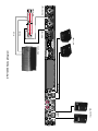
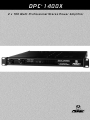
DPC 1400X
®
2 x 7 0 0 Wa t t P r o f e s s i o n a l S t e r e o P ow e r A m p l i f i e r
®
OWNER’S MANUAL
Intended to alert the user to the presence of uninsulated “dangerous voltage” within the product’s
enclosure that may be of sufficient magnitude to constitute a risk of electric shock to persons.
Intended to alert the user of the presence of important operating and maintenance (servicing)
instructions in the literature accompanying the product.
CAUTION: Risk of electrical shock — DO NOT OPEN!
CAUTION: To reduce the risk of electric shock, do not remove cover. No user serviceable parts inside. Refer
servicing to qualified service personnel.
WARNING: To prevent electrical shock or fire hazard, do not expose this appliance to rain or moisture. Before
using this appliance, read the operating guide for further warnings.
Este símbolo tiene el propósito, de alertar al usuario de la presencia de “(voltaje) peligroso” que no tiene
aislamiento dentro de la caja del producto que puede tener una magnitud suficiente como para constituir
riesgo de corrientazo.
Este símbolo tiene el propósito de alertar al usario de la presencia de instruccones importantes sobre la
operación y mantenimiento en la literatura que viene con el producto.
PRECAUCION: Riesgo de corrientazo — No abra.
PRECAUCION: Para disminuír el riesgo de corrientazo, no abra la cubierta. No hay piezas adentro que el usario
pueda reparar. Deje todo mantenimiento a los técnicos calificados.
ADVERTENCIA: Para evitar corrientazos o peligro de incendio, no deje expuesto a la lluvia o humedad este
aparato Antes de usar este aparato, Iea más advertencias en la guía de operación.
Ce symbole est utilisé pur indiquer à l’utilisateur la présence à l’intérieur de ce produit de tension nonisolée dangereuse pouvant être d’intensité suffisante pour constituer un risque de choc électrique.
Ce symbole est utilisé pour indiquer à l’utilisateur qu’il ou qu’elle trouvera d’importantes instructions sur
l’utilisation et l’entretien (service) de l’appareil dans la littérature accompagnant le produit.
ATTENTION: Risques de choc électrique — NE PAS OUVRIR!
ATTENTION: Afin de réduire le risque de choc électrique, ne pas enlever le couvercle. Il ne se trouve à l’intérieur
aucune pièce pouvant être reparée par l’utilisateur. Confier I’entretien à un personnel qualifié.
AVERTISSEMENT: Afin de prévenir les risques de décharge électrique ou de feu, n’exposez pas cet appareil à la
pluie ou à l’humidité. Avant d’utiliser cet appareil, lisez les avertissements supplémentaires situés dans le guide.
Dieses Symbol soll den Anwender vor unisolierten gefährlichen Spannungen innerhalb des Gehäuses
warnen, die von Ausreichender Stärke sind, um einen elektrischen Schlag verursachen zu können.
Dieses Symbol soll den Benutzer auf wichtige Instruktionen in der Bedienungsanleitung aufmerksam
machen, die Handhabung und Wartung des Produkts betreffen.
VORSICHT: Risiko — Elektrischer Schlag! Nicht öffnen!
VORSICHT: Um das Risiko eines elektrischen Schlages zu vermeiden, nicht die Abdeckung enfernen. Es befinden
sich keine Teile darin, die vom Anwender repariert werden könnten. Reparaturen nur von qualifiziertem
Fachpersonal durchführen lassen.
ACHTUNG: Um einen elektrischen Schlag oder Feuergefahr zu vermeiden, sollte dieses Gerät nicht dem Regen
oder Feuchtigkeit ausgesetzt werden. Vor Inbetriebnahme unbedingt die Bedienungsanleitung lesen.
2
ENGLISH
DPC® 1400X
Thank you for purchasing the DPC®1400X! The DPC® 1400X represents years of digital power
amplifier research packed into a one rack space power-house. Delivering 1,400 watts into
4 ohms bridged, or 2 x 700 watts into 2 ohms in stereo, the DPC 1400X reaches new output
heights.
With all connections on the back panel and all the controls on the front panel, the DPC 1400X
is certain to make life a lot easier for the installers and in live performance applications. You’ll
also find Peavey’s patented DDT™ compression circuitry and combo connector inputs two really
convenient and useful extras.
Please read all of this before using the DPC 1400X as it contains important precautions and safety
information.
1
2
3
1
2
3
4
5
6
7
FRONT PANEL FEATURES
STATUS LEDs (1)
Bi-colored LED used to indicate the status of the channel. Channels A and B have separate Status
LEDs to monitor channel conditions. If both LEDs are not lit at power-up, follow the procedure to
check if the fuse needs replacing. If only one channel’s Status LED is lit check to see it the amp
is in bridge mode (4). If the LED is green, this indicates a normal operation. If the LED is red, then
the amplifier is overheated and will shut down for approximately 5 minutes or until cool enough to
operate safely. If the LED pulsates red, this indicates that there is a problem with the amplifier and it
should be serviced by a qualified technician.
INPUT SENSITIVITY (2)
These controls are used to adjust the input gain of each channel. Maximum gain is achieved with
the control turned fully clockwise. In this position the user will achieve maximum system headroom.
If set lower than full clockwise, lower system noise will occur at the expense of headroom.
SIGNAL LED (3)
Bi-colored LED used to indicate the signal status of a channel. If the LED is not lit, this indicates
no signal at the input. This could be caused by bad cables or the Input Sensitivity (2) being set to
zero. If this LED is green, then a signal is present at the input. If the LED is red, this indicates that
DDT compression is occurring. When DDT compression is disabled a red LED indicates signal clipping.
3
MODE SWITCH (4)
This switch is used to change operational modes of the amplifier. When the switch is pressed in,
the unit is placed in bridge mode (bridge mode is explained later in this manual) and uses only the
Channel A input. When the switch is out, the amplifier operates in stereo mode utilizing both inputs.
Accidental selection of bridge mode from stereo mode while the unit is in operation could cause
severe damage to loudspeakers, particularly biamped systems.
DDT SWITCH (5)
This switch is used to enable or defeat the internal DDT™ compression circuitry. Normally the DDT
function should be enabled to minimize the possibility of either or both channels going into clipping
or overload. With DDT defeated, a severe overload could cause the mains fuse to blow as a matter
of course. (DDT is covered in greater detail later in this manual.)
POWER SWITCH (6)
This switch is used to apply power to the unit, thus turning the unit on. Use the status indicators (1)
to verify the actual power condition of the amp.
COOLING VENTS (7)
These vents provide a path for airflow. Since the DPC 1400X is a fan cooled device, it is very
important not to cover these vents or obstruct the flow of air in any way.
BACK PANEL FEATURES
11
10
10
11
7
12
13
8
9
8
9
CHANNEL INPUT (8)
This input features a combo connector that will accept a standard three-pin male XLR, 1/4" TRS
(Tip-Ring-Sleeve), or 1/4" mono plug. An electronically balanced input is available via XLR and
1/4" TRS use. The unit is internally wired for the following:
Input
(+)
(-)
GND
XLR
Pin 2
Pin 3
Pin 1
TRS
Tip
Ring
Sleeve
Unbalanced input is achieved by use of a 1/4" mono plug (patch cable). It is best to keep the
cable from the output device to the input of the DPC 1400X as short as possible during unbalanced
operation.
INPUT THRU (9)
This TRS 1/4" jack is used to daisy chain the inputs of the DPC 1400X to the inputs of other power
amps or devices. Once again, short patch cables are highly recommended to minimize hum.
BINDING POST SPEAKER OUTPUTS (10)
Because of their high current handling capabilities, the binding post is recommended over the
standard 1/4" connector. For this reason, one set of binding posts is provided for each channel of the the
4
DPC 1400X. The binding posts of each channel are wired in parallel with that channel’s 1/4"
outputs. This allows for parallel speaker systems. The minimum impedance in stereo mode is 2
ohms. Use of the amplifier below the minimum 2 ohm rating could result in overheating and thermal
shutdown. In bridge mode connect the banana plug of your speaker cable to the red binding posts
of channels A and B. The red binding post of channel A is the positive output terminal and the
minimum load impedance is increased to 4 ohms while in bridge mode. (Bridge mode is explained
in more detail later in this manual.)
PARALLEL 1/4" SPEAKER OUTPUTS (11)
Two parallel 1/4" speaker output jacks are provided for each channel of the DPC 1400X.
When adding speakers in parallel always keep in mind your total speaker impedance,
insuring that it does not drop below the minimum load impedance rating of the DPC 1400X.
FUSE (12)
The fuse is located in the cap of the fuse holder. If the fuse should fail, IT MUST BE
REPLACED WITH THE SAME TYPE AND VALUE IN ORDER TO AVOID DAMAGE TO TO
EQUIPMENT AND TO PREVENT VOIDING THE WARRANTY. If the amp repeatedly blows
fuses, it should be taken to a qualified service center for repair.
WARNING: THE FUSE SHOULD ONLY BE REPLACED WHEN THE POWER CORD HAS
BEEN DISCONNECTED FROM ITS POWER SOURCE.
AC LINE CORD SOCKET (13)
Provided to accept the removable (IEC) type AC line cord. Connect only to proper source (see back
panel markings.)
INSTALLATION AND CONNECTION
The DPC professional series of power amplifiers is designed for durability in commercial installations
and has the quality of performance required in studio. These units are a standard rack-mount configuration height, and each is cooled by a variable-speed internal fan. All input and output connections
are on the back panel. Additionally, the level controls and selector switches are on the front panel.
The front panel also contains LED indicators for power and DDT activation, and the mains power
switch.
INDUSTRIAL AND COMMERCIAL INSTALLATIONS
For commercial and other installations where sustained high power operation is required, the
amplifiers should be mounted in a standard 19" rack. It is not necessary to leave a rack space
between each amplifier in the stack since each fan pulls air in from the rear and exhausts the hot air
out the front. However, an adequate cool air supply must be provided for the amplifier when rackmounted. The internal fan must have a source of air that is not preheated by other equipment. If
cool, the amplifier will start up in low speed fan operation and will normally stay at low speed
operation unless sustained high power operating levels occur. Then, as the amplifier heat sinks heat
up, the automatic thermal sensing circuitry will increase the fan speed. Depending upon signal
conditions and amp loading, the fan speed may increase to a maximum value, or it may decrease to
a minimum value. This situation is quite normal. If cooling is inadequate due to preheated air or a
reduction of air flow occurs due to blockage of the amplifier inlet/outlet ports, or if the amplifier is
severely overloaded or short circuited, the amplifier thermal sensing system may cause temporary
shutdown of the unit. This is indicated by the status LEDs on the front panel illuminating red.
Depending upon the available cooling air, operation should be restored relatively quickly, and the
5
status LEDs will be illuminated green. In any event, corrective action should be taken to determine
the cause of the thermal shutdown. If the amplifier is not severely overloaded or shorted and air flow
is normal in and out of the amplifier, then steps should be taken to provide a cooler environment for
all the amplifiers. As a general rule, the cooler electronic equipment is operated, the longer its useful
service life.
STUDIO AND FACILITY INSTALLATION
In most low to medium power applications, the power amplifier can be mounted in any configuration.
It is desirable that, if at all possible, the power amplifier be located at the top of an equipment stack.
This will prevent possible overheating of sensitive equipment by the hot air rising from the power
amplifier. As a general rule, most studio requirements will never cause high speed fan operation.
However, if they do, this may indicate that you have not taken the necessary steps to provide
adequate cooling. Remember, closed up in a cabinet, a DPC Series power amplifier will have severe
cooling problems, even at low power levels. Again, inadvertent short circuit or sustained overload
usage could also cause temporary thermal shutdown and/or blowing of the fuse. Also, most home
wiring and electrical circuits are only 15 amps.
BRIDGE MODE
The bridge mode on stereo amplifiers is often misunderstood as to the actual operation and usage.
In basic terms, when a two-channel amplifier is operated in the bridge mode, it is converted into a
single-channel unit with a power rating equal to the sum of both channels’ power ratings at a Load
Rating of twice that of the single channel rating. For example, the DPC 1400X is rated at 700 watts
RMS per channel into 2 ohms. The bridge ratings are 1,400 watts RMS into 4 ohms (minimum load).
Bridge mode operation is accomplished by placing the mode switch in the “BRIDGE” position,
connecting the positive speaker lead to Channel A red binding post, negative speaker lead to
Channel B red binding post, and using Channel A as the input channel. All Channel B input functions
are defeated, and they serve no purpose now. Another common use for the bridge mode is in
subwoofer applications where very high power levels are required to reproduce extreme low
frequencies. Such enclosures usually contain 2 or 4 loudspeakers to handle the power levels
involved. For bridge mode usage, the enclosure impedance must be 4 or 8 ohms—never below
4 ohms!
DDT™
Peavey’s patented DDT (Distortion Detection Technique) compression circuit enables the user to
maximize the performance of the amplifier/speaker combination by preventing the power amp from
running out of headroom (clipping). This compression system is activated by a very unique circuit
that senses signal conditions which might overload the amplifier and activates compression (reduces
the amp gain) when clipping is imminent. Threshold of compression, then, is clipping itself, and no
specific threshold control is used. This technique effectively utilizes every precious watt available for
the power amplifier to reproduce the signal, while at the same time minimizing clipping and distortion
and thus significantly reducing the potential of loudspeaker degradation and damage. The DDT
system is an automatic hands-off approach to the problem of power amplifier clipping. Since the
DPC Series power amplifiers use a fuse for “over current” protection, the DDT compression system
plays even a more important role in continuous performance by preventing each channel from
clipping and overload. Continuous operation at clipping can cause the fuse to blow, but with the DDT
activated, this problem is minimized. For this reason, you should always have the DDT compression
system enabled.
6
DPC® 1400X SPECIFICATIONS
Output Power: (typical value, 120 V AC, 60 Hz):
Input Impedance:
10k ohms unbalanced
Stereo mode, both channels driven
2 ohms, 1,000 W power channel peak music power
4 ohms, 700 W power channel peak music power
8 ohms, 500 W power channel peak music power
Bridge mode
4 ohms, 2,000 W power peak music power
8 ohms, 1,400 W power peak music power
Channel Voltage Gain:
Input attenuator set @ FCW
Stereo mode, 4 ohms, 1 kHz, 30 dB
Bridge mode, 8 ohms, 1 kHz, 39 dB
Frequency Response:
Rated Output Power (120 V AC, 60 Hz):
Stereo mode, both channels driven
+0.5, -3 dB, 1 W RMS, 4 ohms, 3 Hz to 25 kHz
The frequency response is internally controlled to
optimize phase linearity and improve transient
response.
Stereo mode, both channels driven
2 ohms, 1 kHz, 700 W RMS per channel
4 ohms, 1 kHz, 525 W RMS per channel
8 ohms, 1 kHz, 325 W RMS per channel
Bridge mode
4 ohms, 1 kHz, 1,400 W RMS
8 ohms, 1 kHz, 1,000 W RMS
Slew Rate:
The slew rate is internally controlled by a Bessel
filter to optimize phase linearity and improve
transient response. Because of this circuitry,
the amplifier cannot slew rate limit.
Power Bandwidth:
Stereo mode, both channels driven
4 ohms, 10 Hz to 20 kHz
Power Consumption:
Total Harmonic Distortion:
Stereo mode, both channels driven @ rated output
power, 4 ohms 10 A @ 120 V AC
Stereo mode, both channels driven
1 kHz, 4 ohms rated output, less than 0.1%
Cooling System:
Hum and Noise:
Continuously variable speed DC blower
Stereo mode, both channels driven
Below rated output power 4 ohms, greater than
95 dB (A-weighted)
DDT™ Compression System:
Automatic, switchable with LED indicator
Damping Factor:
Dimensions and Height:
Stereo mode, both channels driven
4 ohms, 100 Hz, greater than 500
•
•
•
•
Input Sensitivity:
Input attenuator set @ FCW @ rated output power,
4 ohms, 1.4 V RMS (+3 dBV)
Height 1.75" (4.4 cm)
Width 19" (48.3 cm)
Depth 16.5" (41.9 cm)
Weight 15 lbs. (6.8 kg)
Specifications subject to change without notice.
7
8
Impulse™ 200
Main
Output
Monitor Output
SRC™ 4034
DPC® 1400X Hookup Diagram
SP™112M
Main Input
Monitor
Main
Out
In
Monitor Input
EQ™215FX
FRANÇAIS
DPC® 1400X
Nous vous félicitons pour l’achat de ce DPC® 1400X! Le DPC® 1400X renferme des années de
recherche dans le domaine les amplificateurs numériques dans une unité rack. Avec ses 1400 Watt
sous 4 Ohm en mode bridge ou 2 x 700 Watt sous 2 Ohm en stéréo, le DPC 1400X atteind de nouveaux sommets de puissance.
Toutes les connections sont situées à l’arrière et tous les contrôles sont en façade, de manière à
simplifier au maximum son installation et son utilisation en situation Live. Le DPC 1400X est en plus
équipé de la compression DDT™ brevetée par Peavey et d’entrées de type combo.
Lisez attentivement ce manuel afin d’utiliser correctement votre DPC 1400X correctement et de
respectez les mesures de sécurité nécessaires.
Veuillez-vous référer au <front panel> art situé dans la
section en langue anglaise de ce manuel.
FACE AVANT
LEDS DE STATUT (1)
LEDs bicolores indiquant le statut du canal. Les canaux A et B possèdent chacun leur LED de
statut. Si les deux LEDs restent éteintes à la mise sous tension, suivez la procédure de remplacement des fusibles. Si seule une est allumée, vérifiez que l’amplificateur est en mode bridge (4). Une
LED verte indique une opération normale. Une LED rouge indique que l’amplificateur a surchauffé et
qu’il ne pourra être mis en route avant 5 minutes ou avant qu’il n’atteigne une température suffisament basse. Une LED clignotant en rouge signal qu’il y a un problème avec l’amplificateur et qu’il
doit être réparé par un technicien qualifié.
SENSIBILITES D’ENTREES (2)
Ces boutons de réglage permettent d’ajuster le gain d’entrée pour chaque canal, c’est-à-dire de
déterminer le volume sonore délivré par l’amplificateur de puissance pour un signal d’entrée donné.
Le gain d’entrée maximum (niveau de sensibilité minimale) est obtenu lorsque le bouton est tourné
à fond dans le sens horaire; cette position assure une dynamique maximale au système. Un réglage
inférieur permettra une réduction du niveau de bruit mais aura pour conséquence une réduction de
la dynamique du système.
LEDS SIGNAL (3)
LED bicolore indiquant le statut du canal. Si elle reste éteinte, aucun signal n’est présent en entrée.
Cela peut provenir de connexions défectueuses ou d’un réglage à zéro de la sensibilité d’entrée (4).
Si la LED est de couleur verte, un signal est présent en entrée. Le voyant s’illumine en rouge
lorsque la compression DDT entre en fonction sur le canal. Lorsque le commutateur (5) désactive la
compression DDT, la couleur rouge indique l’écrêtage du signal.
SELECTEUR DE MODE (4)
Ce commutateur permet de sélectionner le mode de fonctionnement stéréo ou bridge. En mode normal, l’amplificateur travaille en stéréo et les deux canaux d’entrée sont utilisés. Lorsqu’il est engagé,
l’amplificateur est en mode bridge et n’utilise que le canal d’entrée A. Il convient de faire preuve de
9
prudence lorsque ce dernier est sélectionné: si le mode Bridge est choisi par accident, cela risque
d’endommager les haut-parleurs, particulièrement si vous travaillez en biamplification. Ce mode sera
présenté plus en détail dans la suite de ce manuel.
COMMUTATEUR DDT (5)
Ce commutateur permet d’activer (Enable) et de désactiver (Defeat) la compression DDT™. En
fonctionnement normal, la compression DDT™ doit être activée afin de minimiser les risques d’écrêtage ou de surcharge d’un ou des deux canaux. Si le système DDT est désactivé, une surcharge
importante sera susceptible de faire sauter le fusible d’alimentation de l’appareil (Le système de
compression DDT Peavey sera présenté plus en détail dans la suite du manuel).
COMMUTATEUR D’ALIMENTATION (6)
Commutateur de type bascule mettant l'amplificateur sous tension. Consultez les LEDs de statut
pour vérifier l’état de fonctionnement de l’amplificateur.
AERATIONS (7)
Assurent une circulation d’air dans l’appareil. Le DPC 1400X est refroidi par ventilateur; il est donc
important de n’obstruer en aucune manière ces aérations.
PANNEAU ARRIERE
10
10
7
11
12
8
9
8
9
ENTREES DES CANAUX (8)
Ces entrées possèdent des connecteurs de type combo acceptant des fiches XLR standard et des
jacks stéréos (type TRS) et monos. Une entrée symétrique (par électronique) est disponible via l’utilisation des fiches XLR ou jacks TRS. L’unité est câblée comme suit:
Entrée
(+)
(-)
Masse
XLR
Pin 2
Pin 3
Pin 1
TRS
Tip(extrémité)
Ring(anneau)
Sleeve(corps)
Utilisée avec un jack mono, l’entrée est asymétrique. Il est préférable d’utiliser un câble le plus court
possible lors de l’utilisation en asymétrique des entrées du DPC 1400X.
PRISE THRU (9)
Cette prise jack est utilisée pour relier les entrées du DPC 1400X aux entrées d’autres amplis de
puissance ou d’autres processeurs. Encore une fois, l’utilisation de câbles aussi courts que possible
est recommendée pour minimiser les risques de souffle et de bruits de fond.
SORTIES SPEAKON (10)
Les modèles exportés possèdent des prises speakon 4 broches. La prise speakon est connectée comme suit: la broche 1+ est la sortie positive et la broche 1- est la sortie négative.
D’autre possibilités de configurations sont possibles via des modifications internes de l’unité.
Pour ce type de modification, consultez votre Centre de Service Peavey.
10
FUSIBLE (11)
Le fusible se situe dans le couvercle du porte-fusible. Si le fusible grille, IL DOIT ÊTRE REMPLACÉ PAR UN FUSIBLE DE MÊME TYPE POUR ÉVITER TOUT DOMMAGE À
L’ÉQUIPEMENT ET POUR NE PAS ANNULER LA GARANTIE. Si l’ampli grille ses fusibles
de manière répétée, il doit être confié à un centre de service qualifié Peavey.
ATTENTION: LE FUSIBLE DOIT ÊTRE REMPLACÉ APRÉS QUE LE CORDON D’ALIMENTATION AIT ÉTÉ DÉCONNECTÉ DE LA SOURCE DE COURANT.
PRISE D’ALIMENTATION (12)
Le DPC 1400X dispose d'une prise d'alimentation IEC. L'appareil doit toujours être relié à la terre.
Votre sécurité en dépend.
INSTALLATION ET CONNEXION
L'amplificateur professionnel DPC 1400X est conçu pour fournir les performances et la qualité
sonore exigées pour des utilisations privées ou professionnelles. Il est aux dimensions rack standard et refroidi par un ventilateur à vitesse variable. Toutes les connexions d’entrée et de sortie se
trouvent sur le panneau arrière. Le panneau avant comporte les LEDs témoin d’alimentation et d’activation de la compression DDT, les commutateur DDT et marche-arrêt, ainsi que les contrôles de
réglage des niveaux et le commutateur de sélection de mode.
INSTALLATION COMMERCIALE ET INDUSTRIELLE
Pour ce genre d’instalation exigeant un fonctionnement à haute puissance, les amplificateurs
doivent être installés dans un rack standard de 19 pouces. Il n’est pas nécessaire de ménager un
espace entre les amplificateurs de la pile car les ventilateurs absorbent l’air extérieur par l’arrière, et
le rejettent par le devant. Toutefois, une source d’air FRAIS doit être fournie à l’amplificateur s’il est
monté en rack. Le ventilateur interne nécessitent une source d'air non réchauffé par le reste de l'installation. L’amplificateur démarre toujours avec le ventilateur en vitesse basse, c'est à dire à la
vitesse d’exploitation normale. Elle ne change que si l’amplificateur est utilisé à des niveaux élevés
d’une manière continue. En cas d'augmentation de température des radiateurs internes, le circuit
automatique de détection thermique fait varier la vitesse du ventilateur. Selon la nature du signal et
la charge de l’amplificateur, la vitesse du ventilateur peut varier. Ceci est normal. Si le refroidissement est inadéquat (air réchauffé, réduction du flux d’air causée par une obstruction des orifices
d’entrée et de sortie de l’amplificateur, surcharge ou court-circuit en sortie de l’appareil), le système
de détection thermique peut provoquer un arrêt temporaire de l’amplificateur. Dans ce cas, les LEDs
de statut s'illumineront en rouge. Selon la quantité d’air frais disponible, l’amplificateur devrait redevenir opérationnel relativement rapidement et les DELs s’illumineront en vert de nouveau. Il est
cependant recommandé de rechercher la cause de l’arrêt thermique de l'appareil et d’y remédier. Si
aucun court-circuit ou aucune surcharge n'est diagnostiquée et que l’air entre et sort normalement
de l’amplificateur, il convient de prendre les dispositions nécessaires pour assurer à tous les amplificateurs utilisés un environnement plus frais. En règle générale, plus le matériel dispose d’air frais,
plus sa durée de vie sera longue.
INSTALLATION PERSONNELLE/STUDIO
Le DPC 1400X peut être utilisé dans n’importe quelle configuration. Dans la mesure du possible, il
est préférable de l’installer au sommet de la pile de matériel, afin d’éviter la surchauffe éventuelle
d’équipements sensibles à l’air chaud ascendant qu’il dégage. En règle générale, l’utilisation privée
ou en studio ne provoquera pas le fonctionnement du ventilateur à haute vitesse. Toutefois, si cela
se produit, il est probable que les précautions nécessaires à un refroidissement adéquat n’ont pas
été prises. De sérieux problèmes de refroidissement se produiront si l'amplificateur est enfermé
11
dans une armoire, même s’il est utilisé à faibles niveaux. Un court-circuit imprévu ou une surcharge
répétée peuvent également provoquer un arrêt thermique temporaire et/ou la destruction du fusible.
MODE BRIDGE
L'intérêt et l’utilisation du mode bridge des amplificateurs stéréos sont souvent mal compris. En termes simples, lorsqu’un amplificateur à deux canaux est utilisé en mode Bridge, il est converti en un
système à un seul canal dont la puissance nominale est égale à la somme des puissances nominales des deux canaux et dont la charge minimum acceptable est le double de celle de chaque
canal. Par exemple, le DPC 1400X a une puissance de 700 watts RMS par canal sous 2 ohms. Par
conséquent, sa puissance nominale en mode bridge est de 1400 watts RMS sous 4 ohms (charge
minimale). Pour mettre l’amplificateur en mode Bridge, mettre le commutateur sur la position
“BRIDGE”. Dans ce mode, la prise speakon libellée "Bridge" doit être utilisée comme connexion de
sortie et c'est le canal A qui fera office de canal d'entrée. Toutes les fonctions du canal B sont désactivées. Utilisez la borne 1+ du canal A comme sortie positive et la borne 1+ du canal B comme
sortie négative. Le mode Bridge sert fréquemment dans les applications avec subwoofer, lorsque
des niveaux très élevés sont exigés pour reproduire fidèlement les fréquences extrêmement basses.
En mode Bridge, l’impédance doit être 4 ou 8 ohms, et jamais en-dessous de 4 ohms.
ATTENTION: En mode Bridge, il est important d’avoir une charge de haut-parleurs toujours
supérieure à 4 Ohm. Cela représente une augmentation para rapport à la charge minimale du mode
stéréo (2 Ohm). Si cette règle n’est pas suivie, l’amplificateur et les haut-parleurs peuvent être
sérieusement endommagés.
COMPRESSION DDT™
Le système breveté de compression DDT™ (Technique de Détection de la Distorsion) de Peavey
permet à l’ingénieur du son de maximiser les performances de l’ensemble amplificateur/haut-parleurs en évitant l'écrêtage tout en conservant une dynamique maximum. Ce système de compression est activé par un circuit original qui détecte les signaux susceptibles de survolter l’amplificateur,
et active la compression (réduit le gain de l'amplificateur) lorsque l’écrêtage est imminent. Le seuil
de compression est le seuil d'écrêtage lui-même et ne nécessite donc aucun réglage. Cette technique permet à l’amplificateur de tirer le meilleur parti de chaque watt disponible tout en minimisant
l’écrêtage et la distorsion, réduisant ainsi les risques de détérioration des haut-parleurs. La compression DDT représente une solution pratique aux problèmes d’écrêtage. Les amplificateurs de la
série PV étant protégés des surcharges par un fusible, la compression DDT joue un rôle d’autant
plus important qu’elle permet des performances ininterrompues en empêchant les canaux de souffrir
d’un écrêtage ou d’une surcharge éventuels. L’exploitation continuelle en surcharge peut occasionner la destruction du fusible, mais ce problème est minimisé par l’utilisation de la compression DDT.
Il est par conséquent toujours recommandé de conserver le système de compression DDT activé.
12
DPC® 1400X CARACTÉRISTIQUES
Puissance de sortie (valeurs typiques,
240 V AC, 50 Hz):
Impédance d’entrée:
10k ohms asymétrique
Mode Stéréo, deux canaux en fonction
2 ohms, 1,000 W crête à crête/canal
4 ohms, 700 W crête à crête/canal
8 ohms, 500 W crête à crête/canal
Mode Bridge
4 ohms, 2,000 W crête à crête
8 ohms, 1,400 W crête à crête
Gain en tension du canal:
Atténuateur d’entrée à o dB
Mode Stéréo, 4 ohms, 1 kHz, 30 dB
Mode Bridge, 8 ohms, 1 kHz, 39 dB
Réponse en fréquence:
Mode Stéréo, deux canaux en fonction
+0.5, -3 dB, 1 W RMS, 4 ohms, 3 Hz à
25 kHz La réponse en fréquence est controllée de manière interne pour optimiser la
linéarité en phase et la réponse des transcientes.
Puissance de sortie annoncée (240 V AC,
50 Hz):
Mode Stéréo, deux canaux en fonction
2 ohms, 1 kHz, 700 W RMS par canal
4 ohms, 1 kHz, 525 W RMS par canal
8 ohms, 1 kHz, 325 W RMS par canal
Mode Bridge
4 ohms, 1 kHz, 1,400 W RMS
8 ohms, 1 kHz, 1,000 W RMS
Slew Rate:
Le slew rate est controllé de manière interne
pour optimiser la linéarité en phase et la
réponse des transcientes. De ce fait, il n’y a
pas de valeur de Slew Rate typique.
Bande passante:
Mode Stéréo, deux canaux en fonction
4 ohms, 10 Hz à 20 kHz
Consommation:
Mode Stéréo, deux canaux en fonction à puis
sance nominale, 4 ohms 5 A @ 240 V AC
Distorsion Harmonique Totale (THD):
Stéréo, deux canaux en fonction
1 kHz, 4 ohms puissance nominale,
moins de 0.1%
Refroidissement:
Ventilateur DC à vitesse variable.
Bruits et ronflements:
Compression DDT™:
Mode Stéréo, deux canaux en fonction
En dessous de la puissance nominale sous
4 ohms, supérieur à
95 dB (Pondération A)
Automatique avec indicateur LED
Poids et dimensions:
•
•
•
•
Facteur d’amortissement:
Mode Stéréo, deux canaux en fonction
4 ohms, 100 Hz, supérieur à 500
Hauteur 4.4 cm
Largeur 48.3 cm
Profondeur 41.9 cm
Poids 6.8 kg
Toutes ces caractéristiques sont sujettes à modifications
sans préavis.
Sensibilité d’entrée:
Atténuateur d’entrée à o dB pour puissance maxi,
4 ohms, 1.4 V RMS (+3 dBV)
13
DEUTSCH
DPC® 1400X
Herzlichen Glückwunsch zum Erwerb Ihres neuen DPC 1400X! Der DPC 1400X repräsentiert jahrelange Forschungsarbeit auf dem Gebiet digitaler Leistungsverstärker. Mit 1400 Watt an 4 Ohm
(gebrückt) oder 2 mal 700 Watt an 2 Ohm in stereo erreicht der DPC 1400X neue
Ausgangsleistungen.
Zieht man alle rückseitigen Anschlüsse und frontseitigen Steuereinrichtungen in Betracht, so wird
sowohl das Leben eines Installateurs als auch das von Live Performance Anwendungen um einiges
erleichtert. So finden Sie auch mit Peaveys patentiertem DDT™ Kompressionsschaltkreis und
Combo-Eingänge zwei brauchbare und sehr nützliche Extras.
Lesen Sie diese Kurzanleitung, bevor Sie mit dem DPC 1400X arbeiten, da hier wichtige
Informationen bezüglich Arbeitssicherheit und Vorsichtsmaßnahmen gegeben sind.
Siehe Diagramm der Frontplatte im englischen Teil des Handbuchs.
FRONT PANEL FEATURES
STATUS LEDs (1)
Bi-farbige LEDs zeigen den jeweiligen Kanalstatus an. Jeder Kanal verfügt über eine separate
Status LED. Leuchtet beim Einschalten des Gerätes keine der beiden LEDs auf, folgen Sie dem
Verfahren zur Kontrolle des Sicherungsersatzes. Überprüfen Sie ob der Verstärker sich im "Bridge"Mode (4) befindet, falls nur eine Status LED anzeigt. Falls die LED grün aufleuchtet so handelt es
sich um den Normalzustand. Ist die LED dagegen rot, zeigt das eine Überhitzung des Verstärkers
und eine Betriebsaussetzung für ca. 5 Minuten an, bis er für einen sicheren Betrieb weit genug
abgekühlt ist. Eine rot pulsierende LED zeigt an, daß mit dem Verstärker etwas nicht stimmt. Lassen
Sie den Verstärker in diesem Fall unbedingt von einer qualifizierten Fachkraft (Service-Techniker)
warten.
INPUT SENSITIVITÄT (2)
Diese Regler werden benutzt, um die Eingangsverstärkung der Kanäle anzupassen. Maximale
Verstärkung wird durch äußersten Rechtsanschlag erreicht. Sie ist gleichzeitig die Position in der der
Anwender das Maximum an System Headroom herausholt. Entspricht die Einstellung nicht dem vollständigen Rechtsan-schlag, dann ergibt sich auch ein entsprechend geringeres Systemrauschen auf
Kosten des Headrooms.
SIGNAL LED (3)
Bi-farbige LEDs zeigen den jeweiligen Kanalstatus an. Leuchtet die LED nicht auf, dann liegt am
Eingang auch kein Signal an. Die Ursache dafür liegt entweder an schlechten Kabeln oder die
Eingangssensitivität (2) steht auf Null. Falls die LED grün aufleuchtet, dann liegt am Eingang auch
ein Signal an. Leuchtet Sie dagegen rot, erfolgt eine DDT Kompression. Ist die DDT Kompression
inaktiviert dient diese LED, wenn sie rot leuchtet als Clip-Anzeige.
BETRIEBSARTEN WAHLSCHALTER (4)
Dieser Schalter wird zur Änderung der Betriebsarten benutzt. Im gedrückten Zustand wird das Gerät
in den "Bridge"-Mode geschaltet (der "Bridge"-Mode wird später erklärt) und benutzt nur den
14
"Channel A" Eingang. Ist der Schalter nicht gedrückt, operiert der Verstärker in der StereoBetriebsart und benutzt beide Eingänge. Versehentliche Wahl des "Bridge"-Mode aus der StereoBetriebsart heraus während des Betriebs kann zu schweren Lautsprecherschäden führen, insbesondere bei zweifach verstärkten Systemen.
DDT SCHALTER (5)
Dieser Schalter dient der Aktivierung oder Deaktivierung des internen DDT™ "COMPRESSION"Schaltkreises. Normalerweise sollte die DDT Funktion freigegeben sein, um Clipping oder Überlastung eines oder beider Kanäle zu minimalisieren. Mit unterdrücktem DDT kann eine Überlastung zur
Auslösung der Hauptsicherung führen. (DDT wird im Anschluß erklärt)
HAUPT-/NETZSCHALTER (6)
Dieser Schalter dient der Geräteeinschaltung. Benutzen Sie die Status LEDs (1) zur Überprüfung
des Verstärkerzustands.
LÜFTUNGSSCHLITZE (7)
Diese Öffnungen stellen einen Belüftungspfad bereit. Da es sich beim DPC 1400X um ein luftgekühltes Gerät handelt, ist es außerordentlich wichtig diese Öffnungen nicht zu versperren noch
die Luftzirkulation in irgend einer Weise zu beeinträchtigen.
RÜCKSEITE
10
10
7
11
12
8
9
8
9
CHANNEL INPUT (8)
Dieser Eingang stellt einen Combo Anschluß zur Aufnahme eines männlichen Standard 3-poligen
XLR Steckers, 1/4" TRS (Tip-Ring-Sleeve), oder 1/4" Monosteckers bereit. Ebenfalls verfügbar ist
ein elektronisch balacierter Eingang als XLR und 1/4" TRS. Intern ist das Gerät wie folgt verdrahtet:
Input
(+)
(-)
GND
XLR
Pin 2
Pin 3
Pin 1
TRS
Tip
Ring
Sleeve
Per Monostecker (Patchkabel) erhalten Sie einen unbalancierten Eingang (Input). In der unbalancierten Betriebsart wird empfohlen das Kabel zwischen Ausgabegerät und dem DPC 1400X
Eingang so kurz wie möglich zu halten.
INPUT THRU (9)
Diese 1/4" TRS Buchse wird benutzt um die Eingänge des DPC 1400X mit denen anderer
Leistungsverstärker oder Geräte im Daisy-Chain-Verfahren miteinander zu verketten. Auch hier
empfehlen wir den Einsatz kurzer Patchkabel zur Minimalisierung von Systembrummen.
SPEAKON LAUTSPRECHERAUSGÄNGE (10)
Ihr DPC 1400X ist werkseitig bereits intern für den stereo/bi-amp Einsatz vorverdrahtet. Auf
der Geräterückseite entspricht Pin 1+ dem positiven und Pin -1 dem negativen Terminal. Zur
15
internen Konfigurationsänderung stehen wei tere Optionen zur Verfügung. Für diese Art der
Modikation empfehlen wir einen autorisierten Peavey Kundendienst aufzusuchen.
Wenn Sie den DPC 1400X im “Bridge” Mode einsetzen (siehe Mode Schalter 4), dann benutzen Sie
Terminal 1+ von Kanal A als positiven Ausgang und Terminal 1+ von Kanal B als negativen
Ausgang.
WARNUNG!:
Im “Bridge” Mode ist es wichtig sicherzustellen, daß die Lautsprecherimpedanz nicht unterhalb der minimalen Impedanzrate von 4 Ohm (nur “Bridge” Mode) adfällt. Dies unterscheidet
sich von der minimalen Impedanz von 2 Ohm im “Stereo” Mode. Das Arbeiten unterhalb des
minimalen Impedanzbereichs kann für den Verstärker, sowohl als auch für den/die im Einsatz
befindlichen Lautsprecher zu ernsthalften Schäden führen.
SICHERUNG (11)
Innerhalb der Aufnahmevorrichtung der Sicherungshalterung befindet sich eine Sicherung.
Wenn die Sicherung durchbrennt, MUSS SIE DURCH EINE DES GLEICHEN TYPS UND
MIT DEM GLEICHEN WERT ERSETZT WERDEN, UM DAS GERÄT ZU SCHÜTZEN UND
DIE GARANTIELEISTUNGEN ZU ERHALTEN. Wenn am Verstärker wiederholt die
Sicherung durchbrennt, muß das Gerät in eine qualifizierte Fachwerkstatt.
WARNUNG: SICHERUNGSWECHSEL NUR BEI ABGEZOGENEM NETZKABEL
VORNEHMEN!
NETZANSCHLUSSBUCHSE (12)
Diese Buchse dient der Aufnahme des Netzkabels. Schließen Sie das Gerät nur an die dafür vorgesehene Netzspannung an. Stellen Sie auf der Gerätrückseite sicher, ob die erforderliche
Gerätespannung mit der des örtlichen EVU übereinstimmt.
INSTALLATION UND ANSCHLUSS
Die professionelle Serie der DPC Leistungverstärker zeichnet sich durch hohe Langlebigkeit in kommerziellen Installationen aus, und entspricht der in Studio- und Heimanwendungen erforderlichen
Performance Qualität. Das Gerät besitzt eine Einbauhöhe von einer HE (Höheneinheit) für die
Rackmontage, gekühlt von einem internen Lüfter mit variabler Geschwindigkeit. Zusätzlich befinden
sich auf dem Front Panel die Regler und Wahlschalter. Des weiteren befinden sich im Front Panel
LEDs zur Anzeige vorhandener Spannung und DDT Aktivierung sowie der Netz- bzw. Hauptschalter.
INDUSTRIELLE UND KOMMERZIELLE INSTALLATIONEN
Für kommerzielle und andere Installationen, wo anhaltende Höchstleistung gefordert wird sollten die
Verstärker in einem Standard 19" Rack montiert werden. Es ist nicht notwendig einen Zwischenraum
von einer HE bei mehreren übereinander montierten Verstärkern einzuhalten, da jeder Lüfter kühle
Luft von hinten ansaugt und auf der Vorderseite erwärmte absondert. Es sollte jedoch für eine
angemessene kühle Luftver-sorgung für rackmontierte Verstärker gesorgt werden. Achten Sie
darauf, daß es sich bei der Luftversorgung nicht um bereits vorgewärmte Luft anderer Geräte handelt. Ist der Verstärker abgekühlt startet der Lüfter mit niedriger Laufgeschwindigkeit und behält
diese auch bei, es sei denn das anhaltende Belastungspegel auftreten. Sobald sich die Kühlrippen
des Verstärkers aufheizen, fährt der automatische Thermoschaltkreis die Lüftergeschwindigkeit
hoch. In Abhängigkeit der Signalzustände und Verstärkerbelastung kann die Lüftergeschwindigkeit
auf einen Maximumwert ansteigen, oder aber auf einen Mindestwert abfallen. Hierbei handelt es
16
sich um einen normalen Vorgang. Erfolgt eine unzulängliche Kühlung infolge vorgewärmter Luft oder
eine Beeinträchtigung der Luftzufuhr infolge einer Blockierung der Zu-und Abluftwege, oder falls der
Verstärker stark überlastet ist oder einen Kurzschluss erlitt, so besteht die Möglichkeit, daß der
Verstärker vom Thermoschaltkreis aus Sicherheitsgründen vorläufig abgeschaltet wird. Dies wird
Ihnen aber auf dem Front Panel anhand der rot aufleuchtenden Status LED angezeigt. Abhängig
von der zur Verfügung stehenden Kühlluft ist eine verhältnismäßig schnelle wieder Inbetriebnahme
sichergestellt, was durch die grün aufleuchtende Status LED gemeldet wird. In jedem Fall sollten Sie
sich um das Problem kümmern, um dessen Aufhebung sicherzustellen.Ist der Verstärker nicht übermäßig belastet oder kurzgeschlossen und ist eine normale Luftzirkulation gewährleistet, dann sollte
dafür gesorgt werden, allen Verstärkern eine angemessen kühlere Umgebung zu verschaffen. Die
generelle Regel lautet, je kühler die Elektronik bedient wird, um so länger die Lebenserwartung.
STUDIO UND ANLAGEN INSTALLATION
Für die meisten kleineren und mittleren Anwendungen läßt sich der Verstärker in jeder Konfiguration
montieren. Es ist wünschenswert, wenn überhaupt realisierbar, daß der Verstärker im Rack immer
das oberste Gerät sein sollte. Das verhindert eine mögliche Überhitzung sensitiver Anlageteile durch
aufwärtsströmende Warmluft. Als generelle Regel dürfen Sie sich merken, daß die meisten Heimund Studioanwendungen nie das Höchstmass der Lüftergeschwindigkeit verursacht. Sollte es trotzdem vorkommen, werden sicherlich nicht die nötigen Schritte für entsprechend angemessene
Kühlung eingeleitet. Bedenken Sie, daß die Leistungsverstärker der DPC Reihe mit starken
Kühlungsproblemen zu kämpfen haben, wenn sie in verschlossenen Gehäusen, etc. untergebracht
sind, selbst bei niedrigem Leistungspegel. Wieder kann eine Funktionsabschaltung des Verstärkers
durch Kurzschluss oder Einsatz bei starker Überlastung durch den Thermoschaltkreis oder das
Ansprechen der Gerätesicherung erfolgen. Hinzu kommt, daß die meisten Haushaltsstromkreise mit
16A abgesichert sind.
"BRIDGE" MODE
Der "Bridge"-Mode wird bei Stereoverstärkern bezüglich der eigentlichen Bedienung und
Handhabung oft missverstanden. Tatsache ist, daß wenn ein 2-Kanal Verstärker im "Bridge" Mode
betrieben wird dieser in eine "Single-Channel" Einheit umgewandelt wird, mit einer Leistung die gleich der Summe der Leistung beider Kanäle und einer doppelten Belastungsbewertung gegenüber
einer "Single-Channel" Bewertung entspricht. Zum Beispiel wird der DPC 1400X mit 700 Watt RMS
an 2 Ohm eingestuft. Die Bewertung im "Bridge" Mode liegt bei 1400 Watt RMS an 4 Ohm (minimale Belastung). Das Gerät schalten Sie in den "Bridge" Mode mit dem "Mode" Schalter und durch
verbinden des positiven Lautsprecheranschlusses mit der roten Anschlussfahne von Kanal A und
des negativen Lautsprecheranschlusses mit der roten Anschlussfahne von Kanal B und Kanal A als
Eingangskanal benutzen. Alle Eingangsfunktionen von Kanal B sind damit außer Betrieb und dienen
keinem weiteren Zweck. Eineweitere Verwendung des "Bridge" Mode liegt in Subwoofer
Anwendungen wo sehr hohe Leistungen gefordert werden um äußerst tiefe Frequenzen zu erzeugen. Solche Gehäuse enthalten gewöhnlich 2 oder 4 Lautsprecher um die involvierten
Leistungsniveaus zu handeln. Im "Bridge" Mode muß die Impedanz 4 Ω oder 8 Ohm betragen niemals aber unter 4 Ohm!
DDT™
Peaveys patentierter DDT (Distortion Detection Technique) Kompressionsschaltkreis gibt dem
Anwender die Freiheit das Leistungsverhalten der Verstärker-/Lautsprecherkombination zu maximieren indem verhindert wird, daß der Verstärker Headroom (Clipping) verliert. Dieses
Kompressionssystem wird durch eine ausgeklügelte Schaltung aktiviert die Signalzustände wahrnimmt die den Verstärker überlasten können und aktiviert den Kompressionsvorgang (Gain
17
Reduktion) bei bevorstehendem Clipping. Die Kompressions-schwelle clipped sich selbst womit
keine spezielle Thresholdsteuerung benötigt wird. Diese Technik nutzt jedes kostbare für den
Verstärker verfügbare Watt effektiv für die Signal-Reproduktion, während gleichzeitig eine
Minimalisierung von Clipping und Verzerrung stattfindet. Dadurch wird eine Signifikante Reduzierung
einer potentiellen Lautsprecherbeschädigung erreicht. Das DDT System ist eine automatische
"HÄNDE Weg!" Annäherung bezogen auf das Verstärkerproblem Clipping. Seitdem in der DPC
Verstärkerreihe eine Sicherung für den Überspannungsschutz eingesetzt wird, spielt das DDT
Kompressionverfahren eine noch wichtigere Rolle bei der ständigen Leistungssteigerung jeden
Kanal vor Überlastungen und Clipping zu schützen. Ein Clipping Dauerbetrieb kann das Ansprechen
der Sicherung zur Folge haben, doch mit aktiviertem DDT ist dieses Problem minimalisiert. Aus
diesem Grund sollten Sie das DDT Kompressionssystem immer freigeben.
18
DPC® 1400X SPEZIFIKATIONEN
Ausgangsleistung: (typischer Wert, 120 V AC,
60 Hz):
Channel Spannungs Gain:
Input Dämpfer eingestellt @ FCW
Stereo Mode, 4 Ohm, 1 kHz, 30 dB
Bridge Mode, 8 Ohm, 1 kHz, 39 dB
Stereo Mode, beide Kanäle getrieben
2 Ohm, 1000 W Kanal Spitzenleistung
4 Ohm, 700 W Kanal Spitzenleistung
8 Ohm, 500 W Kanal Spitzenleistung
Bridge Mode
4 Ohm, 2,000 W Spitzenleistung
8 Ohm, 1,400 W Spitzenleistung
Frequenzgang:
Stereo Mode, beide Kanäle getrieben
+0.5, -3 dB, 1 W RMS, 4 Ohm, 3 Hz zu
25 kHz Der Frequenzgang wird intern gesteuert, um die Phasenlinearität und
Anstiegszeit zu opt-imieren.
Ausgangsleistung (120 V AC, 60 Hz):
Stereo Mode, beide Kanäle getrieben
2 Ohm, 1 kHz, 700 W RMS pro Kanal
4 Ohm, 1 kHz, 525 W RMS pro Kanal
8 Ohm, 1 kHz, 325 W RMS pro Kanal
Bridge Mode
4 Ohm, 1 kHz, 1,400 W RMS
8 Ohm, 1 kHz, 1,000 W RMS
Slew Rate (Anstiegszeit):
Die Slew Rate wird intern von einem Bessel Filter
gesteuert, um die Phasenlinearität und
Anstiegs-zeit zu optimieren. Wegen dieser
Schaltung kann der Verstärker die
Anstiegszeit nicht begrenzen.
Leistungsbandbreite:
Leistungsaufnahme:
Stereo Mode, beide Kanäle getrieben
4 Ohm, 10 Hz zu 20 kHz
Stereo Mode, beide Kanäle getrieben @
angegebener Ausgangsleistung, 4 Ohm 5 A
@ 240 V AC
Total Harmonic Distortion:
Stereo Mode, beide Kanäle getrieben
1 kHz, 4 Ohm Output, weniger als 0.1%
Kühlsystem:
Gleichspannungslüfter mit kontinuierlich variabler
Geschwindigkeit
Brummen und Rauschen:
Stereo Mode, beide Kanäle getrieben
unterhalb der Ausgangsleistung 4 Ohm,
größer als 95 dB (A-gewichtet)
DDT™ Kompressionssystem:
Automatisch, umschaltbar mit LED Anzeige
Abmessungen und Höhe:
Dämpfungsfaktor:
• Höhe 1.75" (4.4 cm)
• Breite 19" (48.3 cm)
• Tiefe 16.5" (41.9 cm)
• Gewicht 15 lbs. (6.8 kg)
Stereo Mode, beide Kanäle getrieben
4 Ohm, 100 Hz, größer als 500
Input Sensitivität:
Input Dämpfung @ FCW @ angegebener
Ausgangs-leistung, 4 Ohm, 1.4 V RMS (+3 dBV)
Spezifikationen unterliegen unangekündigter Änderungen
Input Impedanz:
10k Ohm unbalanciert
19
ESPAÑOL
DPC® 1400X
¡Gracias por su compra del DPC® 1400X! Esta unidad representa muchos años de investigación en
amplificadores de potencia digitales concentrados en un dispositivo de potencia que ocupa un único
espacio de bastidor. Con la entrega de 1400 W sobre 4 Ω en puente o 2 x 700 W estereofónicos, el
DPC 1400X alcanza nuevos niveles de potencia de salida.
Con todas sus conexiones en el panel posterior y todos los controles en el frontal, el DPC 1400X
hace mucho más fácil el trabajo de instalación y las aplicaciones para las presentaciones en vivo.
También encontrará que el circuito de compresión DDT™ (Técnica de Detección de Distorsión)
patentado por Peavey y los conectores de entrada combinados son dos funciones adicionales muy
convenientes y útiles.
Lea toda la información antes de utilizar el amplificador DPC 1400X, dado que contiene precauciones importantes e información sobre seguridad.
Consulte los diagramas del panel delantero en la sección de inglés de est manual.
FUNCIONES DEL PANEL FRONTAL
LED INDICADORES DE ESTADO (1)
Se emplean LED bicolores para indicar el estado de los canales. Los canales A y B tienen LED indicadores de estado separados para monitorear las condiciones del canal. Si ninguno de los LED se
ilumina al alimentar eléctricamente el equipo, siga el procedimiento para verificar si el fusible necesita reemplazo. Si sólo se ilumina un LED indicador de estado, verifique si el amplificador está en el
modo de puente (4). Si el LED se enciende de color verde, el funcionamiento es normal. Si se
enciende de color verde, el amplificador se ha recalentado y se apaga durante 5 minutos aproximadamente o hasta que se enfríe lo suficiente para funcionar con seguridad. Si el LED titila en rojo,
hay un problema en el amplificador y éste debe ser revisado por un técnico calificado.
SENSIBILIDAD DE ENTRADA (2)
Estos controles se emplean para ajustar la ganancia de entrada de cada canal. La ganancia máxima se logra con el control girado totalmente hacia la derecha. En esta posición, el usuario logra el
nivel máximo de tolerancia de la señal del sistema. Si se configura en una posición menor que el
nivel máximo, habrá menos ruido en el sistema a expensas de más tolerancia al máximo nivel de
señal.
LED INDICADOR DE SEÑAL (3)
LED indicador bicolor empleado para indicar el estado de la señal. Si el LED no se ilumina, no hay
señal en la entrada. Esto puede ser causado por cables en mal estado o por la sensibilidad de
entrada (2) configurada en cero. Si se enciende de color verde, hay una señal presente en la entrada. Si se enciende de color rojo, se está produciendo la compresión DDT. Cuando la compresión
DDT está desactivada, se enciende de color rojo para indicar que se está produciendo el recorte de
la señal.
CONMUTADOR DE MODO (4)
Este conmutador se emplea para cambiar el modo del amplificador. Cuando el conmutador se presiona hacia adentro, la unidad se coloca en el modo de puente (este modo se describe más ade20
lante en este manual) y utiliza sólo la entrada del canal A. Cuando el conmutador está hacia afuera,
el amplificador funciona en el modo estereofónico y utiliza ambas entradas. Si el amplificador está
funcionando en el modo estereofónico y se selecciona accidentalmente el modo de puente, pueden
ocurrir daños graves a los altavoces, especialmente en los sistemas biamplificados.
INTERRUPTOR DDT (5)
Este interruptor se utiliza para activar y desactivar el circuito interno de compresión DDT™.
Normalmente, la función DDT está habilitada para minimizar la posibilidad de que uno o ambos
canales recorten la señal o se sobrecarguen. Con el circuito DDT anulado, una sobrecarga muy
intensa puede hacer que se queme el fusible. (El circuito DDT se describe con mayor detalle más
adelante en este manual.)
INTERRUPTOR DE ALIMENTACIÓN (6)
Este interruptor se utiliza para encender la unidad aplicándole alimentación eléctrica. Utilice los indicadores de estado (1) para verificar la condición actual de la alimentación eléctrica del amplificador.
RANURAS DE ENFRIAMIENTO (7)
Estas ranuras proveen un camino para el flujo de aire. El DPC 1400X es un dispositivo enfriado por
ventilador, de modo que es muy importante no cubrir esas ventilaciones y no obstruir el flujo de aire
de ninguna manera.
FUNCIONES DEL PANEL POSTERIOR
10
10
7
11
12
8
9
8
9
ENTRADA DE CANALES (8)
Esta entrada presenta un conector combinado que acepta un enchufe XLR macho estándar de tres
terminales, un enchufe TRS (punta-anillo-manguito) de 1/4 pulg. o un enchufe monoaural de 1/4
pulg. Se dispone de una entrada balanceada electrónicamente mediante el empleo del conector
XLR o el conector TRS de 1/4 pulg. La unidad está cableada internamente del siguiente modo:
Entrada
(+)
(–)
TIERRA
XLR
Terminal 2
Terminal 3
Terminal 1
TRS
Punta
Anillo
Manguito
La entrada no equilibrada se logra mediante un enchufe macho de 1/4 pulg. monoaural (cable para
conexión temporal). Durante el funcionamiento no equilibrado es mejor mantener el cable entre el
dispositivo de salida y la entrada al DPC 1400X tan corto como sea posible.
ENTRADA PASANTE (9)
Este enchufe hembra TRS de 1/4 pulg. se utiliza para interconectar en cadena las entradas del
amplificador DPC 1400X a las entradas de otros amplificadores de potencia u otros dispositivos.
Nuevamente son altamente recomendable los cables para conexión temporal cortos para minimizar
los zumbidos.
21
SALIDA SPEAKON PARA ALTAVOCES (10)
El DPC 1400X incluye precableado interno de fábrica para uso como amplificador estereofónico y biamplificador. Tal como se indica en la parte posterior de la unidad, el terminal 1+
es positivo y el 1– es negativo. También se dispone de otras opciones para cambiar la configuración internamente. Para realizar esta modificación, recomendamos consultar in Centro
de Servicio Autorizado Peavey.
Al usar el DPC 1400X en el modo de puente (vea el conmutador de modo 4), utilice el terminal 1+
del canal A como salida positiva y el terminal 1+ del canal B como salida negativa.
ADVERTENCIA:
!Al operar en el modo de puente, es importante asegurarse de que la impedancia de los
altavoces no sea inferior a la mínima impedancia nominal de 4 Ω (únicamente para el modo
de puente). Este valor difiere de la impedancia mínima para el modo estereofónico, que es
de 2 Ω. Si el amplificador se hace funcionar con una impedancia inferior a la impedancia
mínima, pueden ocurrir daños graves al amplificador y a los altavoces conectados.
FUSIBLE (11)
El fusible está ubicado en la tapa del portafusible. Si el fusible falla, SE DEBE REEMPLAZAR POR UNO DEL MISMO TIPO Y VALOR A FIN DE EVITAR DAÑOS AL EQUIPO Y
LA ANULACIÓN DE LA GARANTÍA. Si el amplificador quema el fusible repetidamente,
debe ser revisado por un técnico calificado para su reparación.
ADVERTENCIA: EL FUSIBLE SÓLO SE DEBE REEMPLAZAR SI SE HA DESCONECTADO EL CABLE DE ALIMENTACIÓN ELÉCTRICA.
ZÓCALO PARA CORDÓN DE LÍNEA DE CA (12)
Se provee para recibir el cordón de la línea de CA de tipo IEC desenchufable. Conéctelo solamente
a una fuente de alimentación apropiada (vea las marcas en el panel posterior).
INSTALACIÓN Y CONEXIÓN
La serie de amplificadores de potencia profesionales DPC está diseñada para ser duradera en
instalaciones comerciales y ofrece la calidad de desempeño requerida por estudios de grabación y
el uso domiciliario. Estas unidades tienen la altura necesaria para la configuración de montaje en
bastidores estándar y cada una está enfriada por un ventilador interno de velocidad variable. Todas
las conexiones de entrada y salida están en el panel posterior. Además, los controles de nivel y los
conmutadores selectores están en el panel frontal. El panel frontal también tiene LED indicadores
de alimentación eléctrica y de activación del circuito DDT, e incluye el interruptor de alimentación de
línea.
INSTALACIONES INDUSTRIALES Y COMERCIALES
En las instalaciones comerciales y en otras en las que se requiere el funcionamiento continuo con
alta potencia, los amplificadores se deben montar en bastidores estándar de 19 pulg. No es necesario dejar un espacio de bastidor libre entre cada amplificador de la misma columna, dado que
cada ventilador aspira aire desde la parte posterior y expele el aire caliente por el frente. Sin embargo, cuando el amplificador está montado en un bastidor, se debe prever el suministro adecuado de
aire frío. El ventilador interno debe tener una fuente de aire que no esté precalentado por otro
equipo. Si el amplificador está frío, arranca con el ventilador funcionando a baja velocidad y normalmente permanece a baja velocidad, a menos que haya una operación continua con alta potencia.
Entonces, a medida que se calientan los disipadores de calor del amplificador, el circuito de sensado térmico automático incrementa la velocidad del ventilador. En función de las condiciones de la
22
señal y de la carga del amplificador, la velocidad del ventilador puede aumentar hasta un valor máximo o disminuir hasta un valor mínimo. Esta situación es completamente normal. Si el enfriamiento
es inadecuado debido al aire precalentado o a que se produce una reducción del flujo de aire por
bloqueo de los orificios de entrada/salida, o si el amplificador está sobrecargado en exceso o en
cortocircuito, el circuito de sensado térmico automático puede producir el apagado temporario de la
unidad. Esto es indicado por los LED indicadores de estado en el panel frontal, que se iluminan de
color rojo. Según la disponibilidad de aire para enfriamiento, el funcionamiento se restablece en
forma relativamente rápida y los LED indicadores de estado se iluminan de color verde. De todos
modos, se deben adoptar medidas correctivas para determinar la causa del apagado térmico. Si el
amplificador no está sobrecargado en exceso, no está en cortocircuito y el flujo de aire hacia adentro y hacia afuera del amplificador es normal, se deben tomar medidas para proveer un ambiente
más frío a todos los amplificadores. Como regla general, cuanto más frío sea el funcionamiento de
un equipo electrónico, tanto más larga será su vida de servicio útil.
INSTALACIONES EN ESTUDIOS DE GRABACIÓN Y OTROS LUGARES
En la mayoría de las aplicaciones con potencias bajas y medias, el amplificador se puede montar
en cualquier configuración. De ser posible, es preferible que el amplificador de potencia esté ubicado en la parte superior de una columna de equipos. Esto evita posibles recalentamientos de los
equipos sensibles por el aire caliente que se eleva desde el amplificador. Como regla general, la
mayoría de los requerimientos domiciliarios y de estudios de grabación nunca requieren el funcionamiento del ventilador a alta velocidad. Sin embargo, si esto ocurre, puede indicar que no se
han adoptado las medidas necesarias para proveer un enfriamiento adecuado. Recuerde que, si un
amplificador de potencia de la serie DPC se encierra en un gabinete, habrá problemas de enfriamiento graves, aún a niveles de potencia bajos. Nuevamente, un cortocircuito inadvertido o el
empleo continuo con sobrecargas pueden también provocar el apagado temporario por exceso de
temperatura y/o el quemado del fusible. Además, la mayoría de los cableados y circuitos eléctricos
domiciliarios sólo soportan 15 A de corriente.
MODO DE PUENTE
En los amplificadores de potencia estereofónicos, el funcionamiento y el empleo del modo de
puente a menudo no son bien comprendidos. En términos básicos, cuando un amplificador de dos
canales funciona en el modo de puente, se convierte en una unidad de canal único con una potencia nominal igual a la suma de ambas potencias nominales, aplicada sobre cargas cuyo valor nominal es el doble del valor nominal de cada canal individual. Por ejemplo, supongamos que la potencia nominal de 700 Wef por canal del DPC 1400X se aplica sobre 2 Ω. La suma de potencias en el
modo de puente es entonces de 1400 Wef, aplicados sobre 4 Ω (carga mínima). El funcionamiento
en modo de puente se logra colocando el conmutador de modo en la posición “BRIDGE” (puente),
conectando el conductor positivo del altavoz al borne rojo del canal A y el conductor negativo del
altavoz al borne rojo del canal B, utilizando el canal A como canal de entrada. Todas las funciones
de entrada del canal B quedan anuladas y no se utilizan para ningún propósito. Otro empleo común
del modo de puente es el uso con altavoces subsónicos, en el que se requieren niveles de potencia
muy altos para reproducir frecuencias extremadamente bajas. Tales gabinetes normalmente contienen 2 ó 4 altavoces para manejar los niveles de potencia involucrados. Para el modo en puente,
la impedancia de los gabinetes debe ser 4 u 8 Ω —¡pero nunca menos de 4 Ω!
DDT™
El circuito de compresión DDT (Técnica de Detección de Distorsión), patentado por Peavey, permite
al usuario maximizar el desempeño de la combinación amplificador/altavoz evitando que el amplificador de potencia agote la tolerancia de máximo nivel de señal (y recorte la señal). Este sistema de
23
compresión se activa mediante un circuito exclusivo que detecta condiciones de señal que podrían
sobrecargar al amplificador y, cuando el recorte es inminente, activa la compresión (reduce la
ganancia del amplificador). Entonces, el umbral de compresión es el recorte en sí y no se utiliza
ningún control de umbral específico. Esta técnica aprovecha efectivamente los vatios disponibles
para que el amplificador de potencia reproduzca la señal, al tiempo que minimiza el recorte y la distorsión de la señal, reduciendo así considerablemente la posibilidad de que ocurran degradación del
sonido y daños a los altavoces. El sistema DDT es una solución al problema de recorte en amplificadores de potencia y no requiere la intervención del operador. Como los amplificadores de potencia de la serie DPC utilizan un fusible para protección contra sobrecorrientes, el sistema de compresión DDT desempeña una función aún más importante durante el funcionamiento continuado, pues
evita que los canales tengan recortes o se sobrecarguen. El funcionamiento continuado con
recortes de señal puede hacer que el fusible se queme, pero si el sistema DDT está activado, este
problema se minimiza. Por esta razón, se recomienda tener siempre habilitado el sistema DDT.
24
DPC® 1400x ESPECIFICACIONES
Ganancia de voltaje de canal:
Potencia de salida (valor típico, 120 VCA,
60 Hz):
Atenuador de entrada girado totalmente hacia la
derecha
Modo estereofónico, sobre 4 Ω a 1 kHz, 30 dB
Modo de puente, sobre 8 Ω a 1 kHz, 39 dB
Modo estereofónico, ambos canales en uso
Sobre 2 Ω, 1000 Wpico (musicales) por canal
Sobre 4 Ω, 700 Wpico (musicales) por canal
Sobre 8 Ω, 500 Wpico (musicales) por canal
Modo de puente
Sobre 4 Ω, 2000 Wpico (musicales) por canal
Sobre 8 Ω, 1400 Wpico (musicales) por canal
Respuesta de frecuencia:
Modo estereofónico, ambos canales en uso
+0,5, –3 dB, 1 Wef, sobre 4 Ω de 3 Hz a 25 kHz
La respuesta de frecuencia es controlada internamente para optimizar la linealidad de fase y mejorar la respuesta a las señales transitorias.
Modo estereofónico, ambos canales funcionando:
Modo estereofónico, ambos canales en uso
Sobre 2 Ω a 1 kHz, 700 Wef por canal
Sobre 4 Ω a 1 kHz, 525 Wef por canal
Sobre 8 Ω a 1 kHz, 325 Wef por canal
Modo de puente
Sobre 4 Ω a 1 kHz, 1400 Wef
Sobre 8 Ω a 1 kHz, 1000 Wef
Ancho de banda de potencia:
Velocidad de transición:
La velocidad de transición es controlada internamente por un filtro de Bessel para optimizar la linealidad de fase y mejorar la respuesta a las
señales transitorias. Gracias a este circuito, el
amplificador no limita la velocidad de transición de
la señal.
Modo estereofónico, ambos canales funcionando:
Requisitos de alimentación:
Modo estereofónico, ambos canales en uso con
potencia de salida nominal sobre 4 Ω, con
240 VCA: 5 A (4Ω, con 120 V AC: 10A)
Sobre 4 Ω, de 10 Hz a 20 kHz
Distorsión armónica total:
Sistema de enfriamiento:
Ventilador de velocidad continuamente variable
Modo estereofónico, ambos canales funcionando
a 1 kHz, salida nominal sobre 4 Ω, menor que
0,1 %
Zumbido y ruido:
Sistema de compresión DDT™:
Automático y conmutable con LED indicador
Modo estereofónico, ambos canales en uso
Por debajo de la potencia de salida nominal sobre
4 Ω, mayor que 95 dB (ponderación “A” referida a
la potencia nominal)
Dimensiones físicas:
• Altura: 44 mm
• Ancho: 483 mm
• Profundidad: 419 mm
• Peso: 6,8 kg
Factor de amortiguación:
Modo estereofónico, ambos canales en uso
Sobre 4 Ω, 100 Hz, mayor que 500
Las especificaciones están sujetas a cambios sin previo
aviso.
Sensibilidad de entrada:
Atenuador de entrada girado totalmente hacia la
derecha, con potencia de salida nominal sobre 4
Ω, 1,4 Vef (+3 dBV)
Impedancia de entrada:
10 kΩ no equilibrada
25
THIS LIMITED WARRANTY VALID ONLY WHEN PURCHASED AND REGISTERED IN THE UNITED STATES OR CANADA. ALL EXPORTED PRODUCTS ARE SUBJECT TO
WARRANTY AND SERVICES TO BE SPECIFIED AND PROVIDED BY THE AUTHORIZED DISTRIBUTOR FOR EACH COUNTRY.
Ces clauses de garantie ne vent vaiables qu’aux Etats-Unis et au Canada. Dans tour les autres pays, les clauses de garantie et de maintenance vent fixees par le distributeur national et assuree par lul scion la legislation envigueur. • • Diese Garantie ist nur in den USA and Kanada gultig. Alle ExportProdukte sind der Garantie und dem
Service des Importeurs des jewelligen Landes unterworfen. • • Esta garantia es valida solamente cuando et producto es comprado en E.U. continentales o en Canada. Todos
los productos que seen comprados en el extranjero, estan suietos a las garantias y servicio que cada distribuidor autorizado determine y of rezca en los diferentes paises.
PEAVEY ONE-YEAR LIMITED WARRANTY/REMEDY
PEAVEY ELECTRONICS CORPORATION (“PEAVEY”) warrants this product, EXCEPT for covers, footswitches, patchcords, tubes and meters, to be free from defects in material and
workmanship for a period of one (1) year from date of purchase, PROVIDED, however, that this limited warranty is extended only to the original retail
purchaser and is subject to the conditions, exclusions, and limitations hereinafter set forth:
PEAVEY 90-DAY LIMITED WARRANTY ON TUBES AND METERS
If this product contains tubes or meters, Peavey warrants the tubes or meters contained in the product to be free from defects in material and workmanship for a period of ninety (90)
days from date of purchase; PROVIDED, however, that this limited warranty is extended only to the original retail purchaser and is also subject to the conditions, exclusions, and limitations hereinafter set forth.
CONDITIONS, EXCLUSIONS, AND LIMITATIONS OF LIMITED WARRANTIES
These limited warranties shall be void and of no effect, if:
a. The first purchase of the product is for the purpose of resale; or
b. The original retail purchase is not made from an AUTHORIZED PEAVEY DEALER; or
c. The product has been damaged by accident or unreasonable use, neglect, improper service or maintenance, or other causes not arising out of defects in material or workmanship; or
d. The serial number affixed to the product is altered, defaced, or removed.
In the event of a defect in material and/or workmanship covered by this limited warranty, Peavey will:
a. In the case of tubes or meters, replace the defective component without charge.
b. In other covered cases (i.e., cases involving anything other than covers, footswitches, patchcords, tubes or meters), repair the defect in material or workmanship or replace
the product, at Peavey’s option; and provided, however, that, in any case, all costs of shipping, if necessary, are paid by you, the purchaser.
THE WARRANTY REGISTRATION CARD SHOULD BE ACCURATELY COMPLETED AND MAILED TO AND RECEIVED BY PEAVEY WITHIN FOURTEEN (14) DAYS FROM THE
DATE OF YOUR PURCHASE.
In order to obtain service under these warranties, you must:
a. Bring the defective item to any PEAVEY AUTHORIZED DEALER or AUTHORIZED PEAVEY SERVICE CENTER and present therewith the ORIGINAL
PROOF OF PURCHASE supplied to you by the AUTHORIZED PEAVEY DEALER in connection with your purchase from him of this product
If the DEALER or SERVICE CENTER is unable to provide the necessary warranty service you will be directed to the nearest other PEAVEY AUTHORIZED
DEALER or AUTHORIZED PEAVEY SERVICE CENTER which can provide such service, OR
b. Ship the defective item, prepaid, to:
PEAVEY ELECTRONICS CORPORATION
International Service Center
326 Hwy. 11 & 80 East
Meridian, MS 39301
Including therewith a complete, detailed description of the problem, together with a legible copy of the original PROOF OF PURCHASE and a complete return
address. Upon Peavey’s receipt of these items: If the defect is remedial under these limited warranties and the other terms and conditions expressed herein
have been complied with, Peavey will provide the necessary warranty service to repair or replace the product and will return it, FREIGHT COLLECT, to you,
the purchaser.
Peavey’s liability to the purchaser for damages from any cause whatsoever and regardless of the form of action, including negligence, is limited to the actual damages up to the greater
of $500.00 or an amount equal to the purchase price of the product that caused the damage or that is the subject of or is directly related to the cause of action Such purchase price will
be that in effect for the specific product when the cause of action arose. This limitation of liability will not apply to claims for personal injury or damage to real property or tangible personal property allegedly caused by Peavey’s negligence, Peavey does not assume liability for personal injury or property damage arising out of or caused by a non-Peavey alteration or
attachment, nor does Peavey assume any responsibility for damage to interconnected non-Peavey equipment that may result from the normal functioning and maintenance of the
Peavey equipment.
UNDER NO CIRCUMSTANCES WILL PEAVEY BE LIABLE FOR ANY LOST PROFITS, LOST SAVINGS, ANY INCIDENTAL DAMAGES, OR ANY
CONSEQUENTIAL DAMAGES ARISING OUT OF THE USE OR INABILITY TO USE THE PRODUCT, EVEN IF PEAVEY HAS BEEN ADVISED OF THE POSSIBILITY
OF SUCH DAMAGES.
THESE LIMITED WARRANTIES ARE IN LIEU OF ANY AND ALL WARRANTIES, EXPRESSED OR IMPLIED, INCLUDING, BUT NOT LIMITED TO, THE IMPLIED WARRANTIES OF MERCHANTABILITY AND FITNESS FOR A PARTICULAR USE: PROVIDED, HOWEVER, THAT IF THE OTHER TERMS AND CONDITIONS NECESSARY TO THE EXISTENCE OF THE EXPRESSED, LIMITED WARRANTIES, AS HEREINABOVE STATED, HAVE BEEN COMPLIED WITH, IMPLIED
WARRANTIES ARE NOT DISCLAIMED DURING THE APPLICABLE ONE-YEAR OR NINETY-DAY PERIOD FROM DATE OF PURCHASE OF THIS PRODUCT.
SOME STATES DO NOT ALLOW LIMITATION ON HOW LONG AN IMPLIED WARRANTY LASTS, OR THE EXCLUSION OR LIMITATION OF INCIDENTAL
OR CONSEQUENTIAL DAMAGES, SO THE ABOVE LIMITATIONS OR EXCLUSIONS MAY NOT APPLY TO YOU. THESE LIMITED WARRANTIES GIVE YOU SPECIFIC LEGAL
RIGHTS, AND YOU MAY ALSO HAVE OTHER RIGHTS WHICH MAY VARY FROM STATE TO STATE.
THESE LIMITED WARRANTIES ARE THE ONLY EXPRESSED WARRANTIES ON THIS PRODUCT, AND NO OTHER STATEMENT, REPRESENTATION, WARRANTY, OR
AGREEMENT BY ANY PERSON SHALL BE VALID OR BINDING UPON PEAVEY.
In the event of any modification or disclaimer of expressed or implied warranties, or any limitation of remedies, contained herein conflicts with applicable law, then such modification, disclaimer or limitation, as the case may be, shall be deemed to be modified to the extent necessary to comply with such law.
Your remedies for breach of these warranties are limited to those remedies provided herein and Peavey Electronics Corporation gives this limited warranty only with respect
to equipment purchased in the United States of America.
INSTRUCTIONS—WARRANTY REGISTRATION CARD
1. Mail the completed WARRANTY REGISTRATION CARD to:
PEAVEY ELECTRONICS CORPORATION
P.O. BOX 2898
Meridian, MS 39302-2898
a. Keep the PROOF OF PURCHASE In the event warranty service is required during the warranty period, you will need this document. There will be no identification card issued
by Peavey Electronics Corporation
2. IMPORTANCE OF WARRANTY REGISTRATION CARDS AND NOTIFICATION OF CHANGES OF ADDRESSES:
a. Completion and mailing of WARRANTY REGISTRATION CARDS—Should notification become necessary for any condition that may require correction the REGISTRATION CARD
will help ensure that you are contacted and properly notified.
b. Notice of address changes - If you move from the address shown on the WARRANTY REGISTRATION CARD, you should notify Peavey of the change of address so as to facilitate your receipt of any bulletins or other forms of notification which may become necessary in connection with any condition that may require dissemination of information or correction.
3. You may contact Peavey directly by telephoning (601) 483-5365.
26
IMPORTANT SAFETY INSTRUCTIONS
WARNING: When using electric products, basic cautions should always be followed. including the following.
1. Read all safety and operating instructions before using this product.
2.
All safety and operating instructions should be retained for future reference.
3.
Obey all cautions in the operating instructions and on the back of the unit.
4.
All operating instructions should be followed.
5.
This product should not be used near water, i.e., a bathtub, sink, swimming pool, wet basement, etc.
6.
This product should be located so that its position does not interfere with its proper ventilation. It should not be placed flat against a wall
or placed in a built-in enclosure that will impede the flow of cooling air.
7.
This product should not be placed near a source of heat such as a stove, radiator, or another heat producing amplifier.
8.
Connect only to a power supply of the type marked on the unit adJacent to the power supply cord.
9.
Never break off the ground pin on the power supply cord. For more information on grounding, write
for our free booklet “Shock Hazard and Grounding."
10. Power supply cords should always be handled carefully. Never walk or place equipment on power supply cords. Periodically check cords for
cuts or signs of stress, especially at the plug and the point where the cord exits the unit.
11 The power supply cord should be unplugged when the unit is to be unused for long periods of time.
12. If this product is to be mounted in an equipment rack, rear support should be provided.
13. Metal parts can be cleaned with a damp rag. The vinyl covering used on some units can be cleaned with a damp rag or an ammonia-based
household cleaner if necessary. Disconnect unit from power supply before cleaning.
14. Care should be taken so that objects do not fall and liquids are not spilled into the unit through the ventilation holes or any other openings.
15. This unit should be checked by a qualified service technician if:
a. The power supply cord or plug has been damaged.
b. Anything has fallen or been spilled into the unit.
c. The unit does not operate correctly.
d. The unit has been dropped or the enclosure damaged.
16. The user should not attempt to service this equipment. All service work should]d be done by a qualified service technician.
17. This product should be used only with a cart or stand that is recommended by Peavey Electronics.
18. Exposure to extremely high noise ]levels may cause a permanent hearing loss. individuals vary considerably in susceptibility to noise induced
hearing loss, but nearly everyone will lose some hearing if exposed to sufficiently intense noise for a sufficient time. The U.S. Government’s
Occupational Safety and Health Administration (OSHA) has specified the following permissible noise level exposures.
Duration Per Day In Hours
8
6
4
3
2
1 1/2
1
1/2
1/4 or less
Sound Level dBA, Slow Response
90
92
95
97
100
102
105
110
115
According to OSHA, any exposure in excess of the above permissible limits could result in some hearing loss. Ear plugs or protectors h1 the ear
canal]s or over the ears must be worn when operating this amplification system in order to prevent a permanent hearing loss if exposure is in excess
of the limits as set forth above. To ensure against potentially dangerous exposure to high Sound pressure levels. it is recommended that all persons
exposed to equipment capable of producing high sound pressure levels such as this amplification system be protected by hearing protectors while
this unit is in operation.
SAVE THESE INSTRUCTIONS!
27
Features and Specifications subject to change without notice
A Product of Peavey Electronic Corporation
711 A Street / Meridian, MS 39301 / U.S.A. / (601) 483-5365 / Fax (601) 486-1278
© 1999
80301828
Printed in the U.S.A. 4/99