1
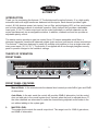
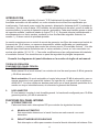
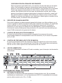
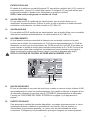
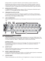
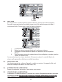
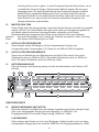
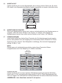
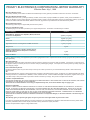
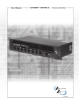
2
AUTOMIX ™
8 Channel Automatic Mixer
OPERATING GUIDE
Intended to alert the user to the presence of uninsulated Òdangerous voltageÓ within the productÕs
enclosure that may be of sufficient magnitude to constitute a risk of electric shock to persons.
Intended to alert the user of the presence of important operating and maintenance (servicing)
instructions in the literature accompanying the product.
CAUTION: Risk of electrical shock Ñ DO NOT OPEN!
CAUTION: To reduce the risk of electric shock, do not remove cover. No user serviceable parts inside. Refer
servicing to qualified service personnel.
WARNING: To prevent electrical shock or fire hazard, do not expose this appliance to rain or moisture. Before
using this appliance, read the operating guide for further warnings.
Este s’mbolo tiene el prop—sito, de alertar al usuario de la presencia de Ò(voltaje) peligrosoÓ que no tiene
aislamiento dentro de la caja del producto que puede tener una magnitud suficiente como para constituir
riesgo de corrientazo.
Este s’mbolo tiene el prop—sito de alertar al usario de la presencia de instruccones importantes sobre la
operaci—n y mantenimiento en la literatura que viene con el producto.
PRECAUCION: Riesgo de corrientazo Ñ ÁNo abra!
PRECAUCION: Para disminu’r el riesgo de corrientazo, no abra la cubierta. No hay piezas adentro que el usario
pueda reparar. Deje todo mantenimiento a los tŽcnicos calificados.
ADVERTENCIA: Para evitar corrientazos o peligro de incendio, no deje expuesto a la lluvia o humedad este
aparato Antes de usar este aparato, Iea m‡s advertencias en la gu’a de operaci—n.
Ce symbole est utilisŽ pur indiquer ˆ lÕutilisateur la prŽsence ˆ lÕintŽrieur de ce produit de tension nonisolŽe dangereuse pouvant •tre dÕintensitŽ suffisante pour constituer un risque de choc Žlectrique.
Ce symbole est utilisŽ pour indiquer ˆ lÕutilisateur quÕil ou quÕelle trouvera dÕimportantes instructions sur
lÕutilisation et lÕentretien (service) de lÕappareil dans la littŽrature accompagnant le produit.
ATTENTION: Risques de choc Žlectrique Ñ NE PAS OUVRIR!
ATTENTION: Afin de rŽduire le risque de choc Žlectrique, ne pas enlever le couvercle. Il ne se trouve ˆ lÕintŽrieur
aucune pi•ce pouvant •tre reparŽe par lÕutilisateur. Confier IÕentretien ˆ un personnel qualifiŽ.
AVERTISSEMENT: Afin de prŽvenir les risques de dŽcharge Žlectrique ou de feu, nÕexposez pas cet appareil ˆ la
pluie ou ˆ lÕhumiditŽ. Avant dÕutiliser cet appareil, lisez les avertissements supplŽmentaires situŽs dans le guide.
Dieses Symbol soll den Anwender vor unisolierten gefŠhrlichen Spannungen innerhalb des GehŠuses
warnen, die von Ausreichender StŠrke sind, um einen elektrischen Schlag verursachen zu kšnnen.
Dieses Symbol soll den Benutzer auf wichtige Instruktionen in der Bedienungsanleitung aufmerksam
machen, die Handhabung und Wartung des Produkts betreffen.
VORSICHT: Risiko Ñ Elektrischer Schlag! Nicht šffnen!
VORSICHT: Um das Risiko eines elektrischen Schlages zu vermeiden, nicht die Abdeckung enfernen. Es befinden sich keine Teile darin, die vom Anwender repariert werden kšnnten. Reparaturen nur von qualifiziertem
Fachpersonal durchfŸhren lassen.
ACHTUNG: Um einen elektrischen Schlag oder Feuergefahr zu vermeiden, sollte dieses GerŠt nicht dem Regen
oder Feuchtigkeit ausgesetzt werden. Vor Inbetriebnahme unbedingt die Bedienungsanleitung lesen.
2
ENGLISH
AUTOMIXª 2
INTRODUCTION
Thank you for purchasing the Automixª 2! The Architectural Acoustics Automixª 2 is a high quality
automatic mixer with eight transformer balanced mic/line inputs. Each channel provides a gain
control, 48 Volt phantom power (mic inputs), low cut filter, activity/clipping LED, an Aux send control
and a choice between manual or automatic operation. Each channel also provides a defeatable
insert point, 5 Volt TTL status output and can be muted individually or multiple channels can be
muted simultaneously via an assignable mutebus. In addition, channels one and two provide an
adjustable priority control.
The master section provides a gain trim control, three 1/9 octave sweepable notch filters, a
downward expander, transformer balanced outputs (main and aux) and remote volume connections.
The Automixª 2 has been designed to easily link multiple units together to form a single mixer with
many more inputs (16, 24, 32...). The Automix 2 is supplied with a see-through plexiglass security
panel to prevent changes to the installerÕs settings.
THEORY OF OPERATION
FRONT PANEL
1
2
FRONT PANEL FEATURES
1.
CHANNEL LEVEL
Manual Mode: In the manual mode the channel level controls provide 6dB of gain and 50dB
of attenuation.
Auto Mode: In the auto mode the control still provides 50dB of attenuation, but the control
does not add gain to the overall system level. Instead, when the level is adjusted above Ò0Ó,
the other channels are attenuated to make the channel being adjusted sound louder in the
mix without adding to the system gain.
2.
MASTER LEVEL
The master level controls the overall output level. The range is set for 10dB of gain above,
and 40dB of attenuation.
3
INTERNAL PANEL
8
3
9
12
10 13
11
4
5
6
7
INTERNAL PANEL FEATURES
3.
DIP SWITCHES
Each channel has four DIP switches that control the following functions.
A.
MAN/AUTO
This switch determines whether the channel is operating in the automatic or manual
mode.
B.
OFF/MBUS
This switch is used to connect the channel to the system mutebus. This allows multiple
inputs to be muted simultaneously under external control. See MUTEBUS, page 7.
C.
LO CUT/FLAT
This switch selects the low cut filter. The low cut filter provides a low frequency rolloff
that will help minimize unwanted noise (handling of mics, bumping of table, etc...). The
rolloff starts at 100 Hz (-3dB) and is a 6dB per octave filter.
D.
OFF/+48
When this switch is in the +48 position, +48 volts of phantom power is supplied to
the mic ± terminals. This provides power for condenser mics and should be
defeated when using dynamic microphones or unbalanced inputs.
4.
AUX SEND CONTROL
Controls the level of the signal being sent to the AUX bus. The level being sent to the Aux
bus will also be affected if the gain control in that channel is changed.
5.
GAIN TRIM
This control sets the input gain in each channel. The amount of gain is adjustable from
+25dB to +60dB. (Mic input.)
6.
ACTIVITY/CLIPPING LED ACTIVITY
In the automatic mode the LED will glow green, indicating the channel that is predominant in
the mix (auto mode). If the channel is in the manual mode the LED will stay on if the front
panel level control is at or above the 12:00 position. The green LED is also an indication of
the status output state. If the LED is on, then the status output will be high (+5 Volts). If the
LED is off, then the status output will be low (0 Volts).
CLIPPING
The LED will turn red if the channel is within 1dB of clipping.
4
7.
PRIORITY (CHANNEL 1 and 2 ONLY)
Turning the priority control clockwise allows one channel to override the others in the mix. It
does this by ÒtrickingÓ the gain computing circuits into thinking this channel is louder than the
others. Up to 9dB of priority is available.
8.
AUX MASTER LEVEL CONTROL
This control sets the level of the signal being sent to the Aux Out. This level should be set
after the individual channel levels have been set.
9.
DOWNWARD EXPANDER
The downward expander can be used to attenuate the system gain when all of the
input signals are low. This can be used to prevent background room noise from being
amplified.
SETTING THE DOWNWARD EXPANDER
Have someone speak into a microphone at the softest level you can expect to
encounter. Slowly turn the downward expander clockwise until the background noise
between words is attenuated. Be careful not to go too far. The more downward
expander that is used, the less ÒnaturalÓ sounding the system will become.
This method will give you a good starting point, but the best way to set the downward
expander is during an actual meeting or event. While doing this, the downward
expander can be adjusted for the best sound. If you have to deal with both loud and
quiet events, you will need to trade off between natural sounding ambient and background noise.
10.
MASTER GAIN TRIM
This control sets the maximum overall system gain and should be set with the front panel
master gain set to the full clockwise position, all channels at unity, and external power amps
turned up and locked at operational settings. When trimmed to a safe margin below feedback,
no combination of user controls can cause feedback. This trim provides up to 25dB of
attenuation of the system gain.
11.
NOTCH FILTER LEVEL CONTROL
The notch filter level control adjusts the amount of cut at the frequency selected by the
corresponding frequency control (12). It is adjustable from 0dB to 15dB of cut.
12.
NOTCH FILTER FREQUENCY CONTROL
The notch filter frequency control is used to select the center frequency of the notch filter. The
bottom filter has a range of 40Hz to 925Hz. The middle filter has a range of 260Hz to
6kHz. The upper filter has a range of 500Hz to 12kHz.
13.
POWER LED
Indicates that AC mains power power is connected and power switch is in the ÒONÓ position.
5
24
23
18
22
19
17
15
16
25
20
14
21
BACK PANEL FEATURES
14.
MIC INPUTS
For use with low impedance microphones or low level sources. This is a transformer balanced
input with an impedance of 2,000½. Input sensitivity for nominal output is -56dBu to -19dBu.
LINE INPUTS
These allow line level inputs to be used. This is a transformer balanced input through a 30dB
resistive pad. Input impedance is >20k½.
15.
INSERT IN/OUT
This is a signal loop that allows an external device such as an EQ to be inserted into the
signal path of individual channels (refer to diagram below).
Insert In/Out
IN
+-G
OUT
G-+
CEQ 280a
16.
INSERT BYPASS SWITCH
When no signal processor is being used or bypassing the signal processor is desired, this
switch should be in the ÒinÓ position. If a signal processor is being used, then this switch
should be in the ÒoutÓ position.
17.
DIRECT OUTPUTS
Each channel has direct output terminals that can be used for recording or anytime the output of an individual channel is required. This signal is independent of ÒAutomixÓ gain manipulation. The nominal output level is 2.21dBu (1 Volt).
6
MUTE
Channels can be muted individually by shorting this terminal to ground. It provides
approximately 45dB of attenuation.
Mute with
External Switch
STATUS OUTPUT
The status output is a DC logic output that is high (+5 Volts) when the channel is active and
low (0Volts) when the channel is not active. This DC voltage can be used to key video
cameras or trigger key lights on active microphones.
NOTE: Each channel can source a maximum of 10 mA.
18.
MAIN OUT
The main output is a 600½, transformer balanced output that can be used to feed an external
power amplifier. It is at this point the automatically mixed or the manually mixed output is
accessed. The nominal output is 2.21 dBu (1 volt).
19.
AUX OUT
The aux output is a 600½, transformer balanced output that can be used as an additional
non-automixed output. The nominal output is 2.21 dBu (1 volt).
20.
REMOTE VOLUME
The master level of the mixer can be controlled remotely with a simple connection on the
back of the unit. A 10k pot will provide approximately 0 to 25dB of attenuation. A 100k pot will
provide 0 to 45dB of attenuation. If desired, a control voltage can be inserted to command 0
to 70dB of attenuation. The internal gain trim must be set full clockwise to achieve the
maximum attenuation range of the remote volume (refer to diagram below).
NOTE: THE CONTROL VOLTAGE SHOULD NEVER EXCEED 13 VOLTS DC.
Mute Bus
Remote Volume
7
21.
22.
MUTEBUS
The mutebus is a control port that when shorted to ground will mute all channels that are
assigned to the mutebus approximately 45dB. The channels to be muted must be assigned
to the mutebus using the internal switch marked OFF/MBUS. See INTERNAL PANEL
FEATURES, page 4 and diagram page 7.
LINK PORT
To increase the number of inputs available, multiple Automixers can be linked together.
Linking automixers is a very simple process. It can be done with a small flat-head screwdriver
and a short length of four conductor shielded wire. The following diagram and procedures will
ensure proper linking.
Link Port
1.
2.
3.
23.
24.
25.
Make a linking cable.
Connect the mixers according to the diagram above.
Select the mixer to be used as the master and place its link switch in the
ÒmasterÓ position.
4.
All other mixers in the system should have their link switches in the ÒslaveÓ
position.
You now have a 16 (or more) channel automatic mixer. The master controls of the unit
chosen as ÒmasterÓ should be used to control the system.
LINK SWITCH
The link switch is used to place the unit in the master or slave mode of operation. A standalone unit should always be in the master mode. See Link Port (#22).
POWER SWITCH
Switch to ÒIÓ position to turn on.
IEC INLET (AC)
With the Power Switch in the off (O) position, plug the power cord into this connector prior to plugging into your AC power source. Always ensure proper AC voltage and grounding practices
are utilized (proper voltage is labeled under inlet).
NOTE: FOR UK ONLY
As the colors of the wires in the mains lead of this apparatus may not correspond with the colored
markings identifying the terminals in your plug, proceed as follows: (1) The wire which is colored
green and yellow must be connected to the terminal which is marked by the letter E or by the earth
symbol or colored green or green and yellow. (2) The wire which is colored blue must be connected
to the terminal which is marked with the letter N or the color black. (3) The wire which is
colored brown must be connected to the terminal which is marked with the letter L or color red.
8
AUTOMIXª 2 SPECIFICATIONS
Nominal Out = 2.21 dBu = 1 Volt
Input Specifications:
Function
Input z
(ohms)
Min
Input Gains
Setting
Microphone
(150 ohms)
2k
Max Gain
(60dB)
Line
(10K ohms)
>20k
Min*
Max Gain
(30dB)
Input Levels
(to bal. outputs)
Nominal**
Bal./
Unbal.
Connector
Max
-64dBu
(0.5mV)
-43dBu
(5.5mV)
-2dBu
(615mV)
Bal.
Mic In (+)
Mic In (-)
Ground
-35dBu
13.7mV
-14dBu
(155mV)
+27dBu
(17.4V)
Bal.
Line In (+)
Line In (-)
Ground
* Minimum input level (Sensitivity) is the smallest signal that will produce nominal output (2.21dBu) with channel and
master controls set for maximum gain.
** Nominal settings are defined s all control set at 0 dB (or 50% rotation for rotary pots.
EIN:
Phantom Power:
Priority (Channels 1 and 2):
Low Cut Filter:
Common Mode:
Rejection Ratio:
-122dBu (Max gain, terminated 150 Ohms)
+48 Volts at Mic ± terminated
0dB to 9dB
-3dB at 100Hz (6dB per octave)
>65dB at 20Hz Ñ 20kHz
>85dB @ 1kHz
Output Specifications:
Function
Main Out
Minimum
Load Z
(Ohms)
Output Levels
Nominal
600
+2.21dBu
+20dBu
+16dBm
(1V)
(7.75V)
(6.44V)
Bal./
Unbal.
Connector
Main Out (=)
Bal.
Main Out (+)
Max
Main Out (-)
(Hi Z load) (600½ load)
Aux Out
600
+2.21dBu
+20dBu
(1V)
(Hi Z load)
+16dBm
(600½ load)
Ground
Bal.
Aux Out (+)
Aux Out (-)
Ground
Distortion:
Mic Input to Main Output:
<0.2% at nominal (20Hz to 20kHz)
Frequency Response:
Mic Input Main Output:
Mic Input to Aux Output:
20Hz to 20kHz +0/-1 dB at nominal
20Hz to 20kHz +0/-1 dB at nominal
9
AUTOMIXª 2 SPECIFICATIONS
Hum and Noise:
Output
Residual Noise
Ref: 0 dBu
Main Out
S/N Ratio
Ref: 2:21 dBu
Test Conditions
-85dBu
87dB
All controls down
-84dBu
86dB
One channel nominal,
Master level nominal
-85dBu
87dB
All controls down
-80dBu
82dB
One channel send
nominal,Monitor master
nominal
Aux Out
(Hum and noise measurements: 22 Hz to 22 kHz BW)
GENERAL SPECS:
Remote volume range:
0dB to 70dB of attenuation
Off channel attenuation:
0dB to 70dB
Mute:
Channel is attenuated 45dB when Mute to ground
connection is made.
MuteBus:
Multiple channels can be attenuation 45dB when MuteBus
to ground connection is made.
Status output:
Status is high (5V) when channel is active. It is low (0V)
when channel is not active.
Power consumption:
AC 120 Volts, 60Hz, Domestic
AC 230 Volts, 50/60 Hz Export
15 watts
Weight:
11 pounds
Dimensions:
Width: 19 inches
Depth: 9 1/4 inches
Height: 3 1/2 inches
10
AUTOMIXª 2
Setting up the Automixª 2
1.
Wiring Inputs and Outputs:
For best results, it is recommended that two-conductor shielded cable is used for all input and
output connections. When making connections remember to observe proper polarity. The
recommended strip length for the detachable screw terminals is 1/2".
2.
Initial Control Settings:
Channel Levels
Channel Gain Trims
Aux Send Controls
Priority
Notch Controls
Downward Expander
Aux Master Level
Master Level
Master Gain Trim
All channels in the ÒautoÓ
3.
(Faceplate)
(Internal)
(Internal)
(Internal)
(Internal)
(Internal)
(Internal)
(Faceplate)
(Internal)
mode
Ñ
Ñ
Ñ
Ñ
Ñ
Ñ
Ñ
Ñ
Ñ
Full
Full
Full
Full
Full
Full
Full
Full
Full
CCW
CCW
CCW
CCW
CCW
CCW
CCW
CW
CCW
Setting the Channel Level:
Set the front panel control (of the channel that is being adjusted) to the middle (12 oÕclock)
position. Connect a mic or line input to the first channel. While someone is speaking into
the mic (in a way that it would normally be used), slowly increase the channel gain trim until a
slight ringing (feedback) is heard or until the clip led begins to blink red occasionally. Turn the
channel gain trim down slowly until the ringing is no longer audible. This is the maximum level
that the gain trim should be set. Turn the external channel level control down (full CCW).
NOTE: The internal master gain trim (#10) may need to be turned up (CW) if the
channels can be easily driven into clipping, or feedback cannot be obtained in the
normal operating range of the internal gain trim control.
Repeat this step for the remaining channels.
Return all of the external channel levels controls to their mid position (12 oÕclock).
4.
Setting the Notch Filter:
The notch filter can be set in a couple of ways. It can be set using test equipment to pinpoint
frequencies that are prone to feedback, or it can be set Òby ear.Ó For the purpose of this
manual, the Òby earÓ method will be described:
A.
B.
C.
D.
Slowly increase the master gain trim (internal) until a slight ringing is audible.
Select the proper frequency range and turn the corresponding level control CW
to about the 12 oÕclock position.
Slowly turn the frequency control back and forth until the ringing is no longer
audible.
Again, slowly increase the master gain trim until ringing is heard. If this is a
different frequency, repeat steps B and C. If it is not a different frequency, try
turning the frequency control while listening to the feedback. Stop when the
feedback is as low as possible. If the feedback is still audible, turn the
corresponding level control CW toward the -15 setting until the feedback is
gone.
11
5.
Setting the Overall Level:
Set the master level control (external) for the desired overall output level. This mixerÕs levels
are now set and the mixerÕs other features (downward expander, low cut and priorities) can
be set as desired for the application.
6.
Attaching the Security Panel:
Attach the security plexiglass with the eight supplied screws. This will prevent any unwanted
tampering with the settings.
12
ESPA„OL
AUTOMIXª 2
INTRODUCCIîN
ÁLe agradecemos haber adquirido el Automixª 2! El Architectural Acoustics Automixª 2 es un
mezclador autom‡tico de alta calidad, con ocho entradas de micr—fono/l’nea equilibradas por
transformador. Cada canal posee control de ganancia, alimentaci—n fantasma de 48 V (entradas de
micr—fono), filtro de corte de bajos, LED indicador de actividad/recorte de se–al, control de se–al de
muestra auxiliar y la opci—n de operaci—n manual o autom‡tica. Cada canal tambiŽn posee un punto
de inserci—n anulable y salida de estado de l—gica TTL (5 V). Se puede silenciar individualmente o
simult‡neamente con varios canales, mediante un bus de silenciado asignable. Adem‡s, los
canales 1 y 2 tienen control de prioridad ajustable.
La secci—n maestra provee un control de recorte de ganancia, tres filtros de muesca con barrido de
frecuencia de 1/9 de octava, un expansor descendente, salidas equilibradas por transformador
(principal y auxiliar) y conexiones para control de volumen remoto. El mezclador Automixª 2 ha sido
dise–ado para interconectar f‡cilmente entre s’ varias unidades y formar un œnico mezclador con
muchas m‡s salidas (16, 24, 32É). Para evitar modificaciones a las configuraciones del instalador,
el mezclador Automix 2 se suministra con un panel de seguridad de plexiglas transparente.
Consulte los diagramas del panel delantero en la secci—n de inglŽs de est manual.
TEORêA DE OPERACIîN
FUNCIONES DEL PANEL FRONTAL
1.
NIVEL DE CANAL
Modo manual: En el modo manual, los controles de nivel de canal proveen 6 dB de ganancia
y 50 dB de atenuaci—n.
Modo autom‡tico: En modo autom‡tico el control aœn provee 50 dB de atenuaci—n, pero no
agrega ganancia al nivel general del sistema. En lugar de ello, cuando el nivel se ajusta por
arriba de Ò0Ó, los otros canales se atenœan para hacer que el canal ajustado predomine en la
mezcla con mayor intensidad sonora, sin aumentar la ganancia del sistema.
2.
NIVEL MAESTRO
El nivel maestro controla el nivel de salida general. La banda est‡ configurada para 10 dB de
ganancia positiva y 40 dB de atenuaci—n.
FUNCIONES DEL PANEL INTERNO
3.
INTERRUPTORES DIP
Cada canal tiene cuatro interruptores DIP que controlan las siguientes funciones:
A.
MANUAL/AUTOMçTICO
Este conmutador determina si el canal funciona en modo manual o en modo
autom‡tico.
B.
DESACTIVADO/BUS DE SILENCIADO
Este interruptor se utiliza para conectar el canal al bus de silenciado del sistema. Esto
13
permite que varias entradas se silencien simult‡neamente mediante un control
externo. Vea BUS DE SILENCIADO en la p‡gina 7.
C.
CORTE DE BAJOS/PLANO
Este conmutador selecciona el filtro de corte de bajos. El filtro de corte de bajos
provee atenuaci—n progresiva de baja frecuencia, que ayuda a minimizar los ruidos no
deseados (movimiento de micr—fonos, golpes en la mesa, etc.). La atenuaci—n
progresiva comienza a 100 Hz (Ð3 dB). Es un filtro de 6 dB por octava.
D.
DESACTIVADO/+48
Cuando este interruptor est‡ en la posici—n +48, se suministran +48 V de alimentaci—n
fantasma a los terminales ± del micr—fono. Esto provee alimentaci—n para los
micr—fonos electrost‡ticos. Se debe desactivar al utilizar micr—fonos din‡micos o
entradas no equilibradas.
4.
CONTROL DE SE„AL DE MUESTRA AUXILIAR
Controla el nivel de la se–al enviada al bus auxiliar. El nivel enviado al bus auxiliar tambiŽn
es afectado si se modifica el control de ganancia del canal.
5.
RECORTE DE GANANCIA
Este control configura la ganancia de entrada a cada canal. La cantidad es ajustable de +25
a +60 dB (entrada de micr—fono).
6.
LED ACTIVIDAD/RECORTE DE SE„AL
En el modo autom‡tico, el LED indicador se enciende de color verde para indicar que el
canal es el predominante en la mezcla (modo autom‡tico). Si el canal est‡ en modo manual,
el LED indicador continœa encendido si el control de nivel del panel frontal est‡ en la posici—n
de las 12:00 horas o m‡s all‡. El LED indicador verde tambiŽn es un aviso del estado de la
salida: si est‡ encendido, el estado de la salida es alto (+5 V); si est‡ apagado, el estado es
bajo (0 V).
RECORTE DE SE„AL
Si el canal est‡ a 1 dB o menos del recorte de la se–al, el LED indicador se enciende
de color rojo.
7.
PRIORIDAD (SîLO EN LOS CANALES 1 y 2)
Al girar el control de prioridad hacia la derecha, se permite que el canal predomine sobre los
otros en la mezcla. Para ello, Òenga–aÓ a los circuitos de c—mputo de ganancia haciŽndolos
creer que este canal tiene mayor intensidad sonora que los otros. Se dispone de hasta 9 dB
de prioridad.
8.
CONTROL DE NIVEL MAESTRO AUXILIAR
Este control configura el nivel de la se–al que se env’a a la salida auxiliar. El nivel se debe
graduar despuŽs de configurar los niveles individuales de los canales.
9.
EXPANSOR DESCENDENTE
El expansor descendente se puede utilizar para atenuar la ganancia del sistema cuando
todas las se–ales de entrada son bajas. Esto se puede aprovechar para evitar que el ruido
ambiente de fondo sea amplificado.
14
CONFIGURACIîN DEL EXPANSOR DESCENDENTE
Pida a otra persona que hable frente a un micr—fono al nivel m‡s bajo que se espera
utilizar. Gire lentamente el expansor descendente hacia la derecha, hasta que se
atenœe el ruido ambiente de fondo entre las palabras. Tenga cuidado de no excederse.
Cuanto m‡s expansor descendente se utilice, menos "natural" ser‡ el sonido del
sistema. Este mŽtodo brinda un buen punto de partida para el ajuste, pero la mejor
manera de configurar el expansor descendente es durante la actuaci—n o evento real.
Esto permite ajustar el expansor descendente para obtener el mejor sonido. Si debe
trabajar con eventos muy ruidosos o muy silenciosos, deber‡ lograr un equilibrio entre
el sonido natural y la anulaci—n del ruido ambiente.
10.
RECORTE DE GANANCIA MAESTRO
Este control establece la m‡xima ganancia general del sistema y se debe configurar con el
control de ganancia maestro del panel frontal girado totalmente a la derecha y el amplificador
externo activado, con los controles fijos en la configuraci—n operacional. Al recortar la
ganancia a un nivel seguro por debajo de la retroalimentaci—n, ninguna combinaci—n de
controles del usuario podr‡ generar esa perturbaci—n. El control de recorte de se–al provee
hasta 25 dB de atenuaci—n de ganancia del sistema.
11.
CONTROL DE NIVEL DE FILTRO DE MUESCA
El control de nivel de filtro de muesca ajusta la magnitud de recorte a la frecuencia
seleccionada mediante el correspondiente control de frecuencia (12). El recorte es ajustable
de 0 a 15 dB.
12.
CONTROL DE FRECUENCIA DE FILTRO DE MUESCA
El control de frecuencia de filtro de muesca se utiliza para seleccionar la frecuencia central
del filtro. El filtro inferior tiene una banda de 40 a 925 Hz; el filtro central tiene una banda de
260 Hz a 6 kHz; el filtro superior tiene una banda de 500 Hz a 12 kHz.
13.
LED DE ALIMENTACIîN
Indica que la alimentaci—n de l’nea de CA est‡ conectada y que el interruptor de alimentaci—n
est‡ activado.
24
23 22
18 19
17
15
16
25
20
14
21
FUNCIONES DEL PANEL POSTERIOR
14.
ENTRADAS DE MICRîFONO
Para utilizar con micr—fonos de baja impedancia o fuentes de bajo nivel. Es una entrada
equilibrada por transformador, con una impedancia de 2000 ½. La sensibilidad de la entrada
para la salida nominal es de Ð56 a Ð19 dBu.
15
ENTRADAS DE LêNEA
Permiten utilizar entradas con nivel de l’nea. Son entradas equilibradas por transformador a
travŽs de un atenuador resistivo de 30 dB. La impedancia de entrada es >20 k½.
15.
ENTRADA/SALIDA DE INSERCIîN
Es un circuito de se–al que permite insertar un dispositivo externo, tal como un ecualizador,
en el camino de la se–al de los canales individuales (consulte el diagrama m‡s abajo).
Insert In/Out
IN
+-G
OUT
G-+
CEQ 280a
16.
INTERRUPTOR DE DERIVACIîN DE SE„AL
Cuando no se utiliza ningœn procesador de se–al o se desea evitar el procesador de se–al,
este interruptor debe estar hacia adentro. Si se utiliza un procesador de se–al, debe estar
afuera.
17.
SALIDAS DIRECTAS
Cada canal tiene terminales de salida directa que se pueden utilizar para grabaci—n o cuando
se necesite la salida de un canal individual. La se–al es independiente de la ganancia del
mezclador Automixª 2. El nivel de salida nominal es 2,21 dBu (1 V).
SILENCIADO DE SONIDO
Los canales se pueden silenciar individualmente conectando este terminal a tierra. Provee
aproximadamente 45 dB de atenuaci—n.
Mute with
External Switch
16
ESTADO DE SALIDA
El estado de la salida es una salida l—gica de CC que est‡ en condici—n alta (+5 V) cuando el
canal est‡ activo, y baja (0 V) cuando est‡ inactivo. El voltaje de CC se puede utilizar para
excitar videoc‡maras o disparar luces indicadoras en micr—fonos activos.
NOTA: Cada canal puede generar un m‡ximo de 10 mA.
18.
SALIDA PRINCIPAL
Es una salida de 600 ½ equilibrada por transformador, que se puede utilizar con un
amplificador de potencia externo. ƒste es el punto en que se accede a la salida mezclada
autom‡tica o manualmente. La salida nominal es 2,21 dBu (1V).
19.
SALIDA AUXILIAR
Es una salida de 600 ½ equilibrada por transformador, que se puede utilizar como una salida
adicional no mezclada autom‡ticamente. La salida nominal es 2,21 dBu (1V).
20.
VOLUMEN REMOTO
El nivel maestro puede ser controlado a distancia con una simple conexi—n en la parte
posterior de la unidad. Un potenci—metro de 10 k½ provee aproximadamente 0 a 25 dB de
atenuaci—n, en tanto que un potenci—metro de 100 k½ provee de 0 a 45 dB. Si se desea, se
puede insertar un voltaje de control para controlar la atenuaci—n de 0 a 70 dB. El recorte de
ganancia interno debe estar configurado completamente hacia la derecha, para lograr la
gama de atenuaci—n m‡xima del volumen remoto (consulte el diagrama m‡s abajo).
NOTA: EL VOLTAJE DE CONTROL NO DEBE NUNCA EXCEDER 13 VCC.
Mute Bus
Remote Volume
21.
BUS DE SILENCIADO
EL bus de silenciado es un puerto de control que, cuando se conecta a tierra, silencia 45 dB
aproximadamente en todos los canales asignados. Los canales a silenciar se asignan al bus
de silenciado utilizando el interruptor interno ÒOFF/MBUSÓ (desactivado/bus de silenciado).
Consulte las FUNCIONES DEL PANEL INTERNO en la p‡gina 4 y el diagrama de la
p‡gina 7.
22.
PUERTO DE ENLACE
Para aumentar la cantidad de entradas disponibles, se pueden interconectar entre s’ varios
mezcladores Automix, mediante un procedimiento muy sencillo. S—lo se requiere un
destornillador de punta plana peque–o y un tramo corto de cable blindado de cuatro
conductores. El diagrama y los procedimientos que siguen aseguran un enlace apropiado.
17
Link Port
1.
2.
3.
Prepare un cable de enlace.
Conecte los mezcladores segœn el diagrama de m‡s arriba.
Seleccione el mezclador a ser utilizado como maestro y coloque su conmutador de
enlace en la posici—n ÒmasterÓ (maestro).
4.
Todos los otros mezcladores del sistema deben tener sus conmutadores de enlace en
la posici—n ÒslaveÓ (esclavo).
Ahora usted cuenta con un mezclador autom‡tico de 16 canales o m‡s. Los controles
maestros de la unidad elegida como "maestra" se utilizar‡n para controlar el sistema.
23.
CONMUTADOR DE ENLACE
El conmutador de enlace se utiliza para colocar la unidad en el modo de operaci—n maestro o
en el modo esclavo. Siempre debe haber una unidad aut—noma en el modo maestro.
Consulte PUERTO DE ENLACE (N¼ 22).
24.
INTERRUPTOR DE ALIMENTACIîN
Para encender el equipo, col—quelo en ÒIÓ.
25.
RECEPTçCULO DE ENTRADA IEC (CA)
Con el interruptor de alimentaci—n en la posici—n de apagado (ÒOÓ), enchufe el cable de
alimentaci—n en este conector antes de enchufarlo en la fuente de alimentaci—n de CA.
Asegœrese de utilizar siempre voltaje de CA y pr‡cticas de conexi—n a tierra
apropiados. (El voltaje adecuado est‡ indicado bajo el recept‡culo.)
18
FRAN‚AIS
AUTOMIXª 2
INTRODUCTION
Nous vous fŽlicitons pour lÕachat de cet Automixª 2. LÕAutomixª 2 Architectural Acoustics est un
mixeur automatique haute qualitŽ possŽdant huit entrŽes micro/ligne symŽtriques (transformateur).
Chaque canal poss•de un contr™le de gain, une alimentation phantom 48 Volt (entrŽes micro), une
filtre coupe-bas, une LED dÕactivitŽ/Žcr•tage, un contr™le Aux send et le choix entre une opŽration
manuelle ou automatique. Chaque canal est par ailleurs ŽquipŽ dÕun insert assignable, dÕune sortie
ÒstatutÓ 5 Volt TTL et peut •tre rendu muet individuellement ou en groupe gr‰ce ˆ un bus Mute. De
plus, les canaux 1 et 2 disposent dÕun contr™le de prioritŽ ajustable.
La section master poss•de un contr™le de gain, trois notch filters 1/9 dÕoctave ˆ frŽquence rŽglable,
un expandeur, des sorties symŽtrisŽes par transformateur (main et aux) et des connexions pour le
contr™le de volume ˆ distance. LÕAutomixª 2 a ŽtŽ con•u pour •tre reliŽ ˆ dÕautres unitŽs afin de
constituer un mixeur possŽdant un plus grand nombre dÕentrŽes (16, 24, 32...). Il est par ailleurs
ŽquipŽ dÕun panneau plexiglass transparent afin dÕŽviter toute modification accidentelle des rŽglages
de lÕinstallateur.
Veuillez-vous rŽfŽrer au<<front panel>> art situŽ dans
la section en langue anglaise de ce manual.
PANNEAU AVANT
CONTROLES DU PANNEAU AVANT
1.
NIVEAU DU CANAL
Mode Manuel: Dans ce mode, les contr™les de niveau permettent un contr™le de gain de
+6dB ˆ -50dB.
Mode Automatique: En mode Automatique, le contr™le fournit toujours jusquÕˆ 50dB
dÕattŽnuation mais nÕaugmentera pas le gain du canal. Cependant, lorsquÕil est rŽglŽ au
dessus de Ò0Ó, le gain des autres canaux est attŽnuŽ afin de rendre le canal concernŽ plus
fort dans le mix mais sans augmenter le gain gŽnŽral.
2.
NIVEAU MASTER
Il contr™le le niveau gŽnŽral de sortie. Sa plage de rŽglage sÕŽtend de +10dB ˆ -40dB.
CONTROLES DU PANNEAU INTERNE
3.
DIP SWITCHS
Chaque canal poss•de quatre DIP switchs gŽrant les fonctions suivantes.
A.
MAN/AUTO
Ce sŽlecteur dŽtermine le mode du canal: automatique ou manuel.
B.
OFF/MBUS
Ce sŽlecteur connecte le canal au bus Mute . Cela permet de rendre muets plusieurs
canaux simultanŽment gr‰ce ˆ un contr™le externe. Voir MUTEBUS, page 7.
19
C.
LO CUT/FLAT
Ce sŽlecteur actionne le filtre coupe-bas. Ce filtre attŽnue les frŽquences graves afin
de minimiser les bruits indŽsirables (manipulation du micro, etc...). La frŽquence de
coupure est fixŽe ˆ 100 Hz (-3dB) et la pente du filtre est de 6dB par octave.
D.
OFF/+48
Lorsque ce sŽlecteur est en position +48, une alimentation Phantom de +48 Volt est
prŽsente aux bornes + et - de lÕentrŽe micro. Cela permet lÕalimentation des micros
passifs mais devra •tre dŽsactivŽ lors de lÕutilisation de micros dynamiques ou
asymŽtriques.
4.
CONTRïLE AUX SEND
DŽtermine le niveau du signal envoyŽ au bus AUX. Ce niveau sera par ailleurs affectŽ par le
contr™le de gain du canal correspondant.
5.
GAIN
DŽtermine le gain dÕentrŽe. La plage de rŽglage sÕŽtend de +25dB ˆ +60dB (entrŽe Micro)
6.
LED DÕƒCRæTAGE/ACTIVITƒ
En mode automatique, la LED sÕallumera en vert pour indiquer quel canal est prŽdominant
dans le mix (mode auto). Si le canal est en mode manuel, la LED restera allumŽe si le
contr™le de niveau du paneau avant est rŽglŽ au dessus de 12h00. La LED indique par
ailleurs lÕŽtat du canal concernŽ: si elle sÕallume (+5 Volt), un signal est prŽsent; si elle est
Žteinte (0 Volts), alors aucun signal nÕest prŽsent.
ECRæTAGE
La LED sÕallumera en rouge si le canal est ˆ 1dB de son point dÕŽcr•tage.
7.
PRIORITƒ (CANAUX 1 ET 2 UNIQUEMENT)
En tournant le contr™le dans le sens horaire, le canal concernŽ devient prŽdominant dans le
mix. JusquÕˆ 9 dB de gain sont disponibles.
8.
CONTRïLE DE NIVEAU MASTER AUX
Ce contr™le dŽtermine le niveau du signal envoyŽ ˆ la sortie Aux Out. Ce contr™le doit •tre
ajustŽ aprŽs que les niveaux individuels des canaux aient ŽtŽ rŽglŽs.
9.
EXPANDEUR
LÕexpandeur permet de diminuer le gain des canaux lorsque leurs signaux sont bas. Ceci
permet de ne pas amplifier les bruits de fond.
RƒGLAGE DE LÕEXPANDEUR EXPANDEUR
Parlez dans le micro au niveau le plus faible nŽcessitant dÕ•tre entendu ˆ travers le
syst•me . Tournez lentement le contr™le de lÕexpandeur dans le sens des aiguilles
dÕune montre jusquÕˆ ce que le bruit de fond prŽsent entre les paroles dispara”sse. Ne
poussez pas ce contr™le trop loin. Plus lÕexpandeur est sollicitŽ, moins le rŽsultat sera
naturel. Cette mŽthode vous donne un bon point de dŽpart mais la meilleure mani•re
de rŽgler lÕexpandeur est de le faire en situation. LÕexpandeur sera ainsi ajustŽ pour le
meilleur rendu possible. Si il doit •tre utilisŽ dans des applications bruyantes, il vous
faudra trouver un Žquilibre entre bruit ambient et bruit de fond.
10.
GAIN MASTER
Ce contr™le dŽtermine le gain gŽnŽral du syst•me et doit •tre rŽglŽ avec le gain master du
20
panneau avant sur sa position maximum, tous les canaux au niveau nominal et les
amplificateurs de puissance en marche et ˆ leur niveau dÕutilisation normale. Lorsque le
niveau est Žtabli en dessous du niveau de feedback, aucune manipulation en face avant
nÕentra”nera de larsen. Ce rŽglage permet jusquÕˆ 25dB dÕattŽnuation du gain du syst•me.
11.
NIVEAU DU NOTCH FILTER
Ce rŽglage dŽtermine lÕintensitŽ de la coupure du filtre ˆ la frŽquence sŽlectionnŽe par le
contr™le n¡12. Il est ajustable de 0dB ˆ 15dB de coupure.
12.
FRƒQUENCE DU NOTCH FILTER
Ce contr™le permet de dŽterminer la frŽquence centrale du notch filter. La frŽquence de
centrage du filtre Graves peut varier de 40Hz ˆ 925Hz, celle du filtre MŽdiums de 260Hz ˆ
6kHz et celle du filtre Aigus de 500Hz ˆ 12kHz.
13.
LED DÕALIMENTATION
Indique que lÕappareil est branchŽ et que lÕinterrupteur de mise sous tension est en position
ÒONÓ.
24
23 22
18 19
17
15
16
25
20
21
14
CONTROLES DU PANNEAU ARRIéRE
14.
ENTRƒES MICRO
Cette entrŽe est destinŽe aux micros basse impŽdance et aux sources ˆ faible niveau. Ces
entrŽes sont symŽtrisŽes par transformateur est poss•dent une impŽdance dÕentrŽe de 2 k½.
Un niveau dÕentrŽe de -56dBu ˆ -19dBu produit un niveau de sortie nominal.
ENTRƒES LIGNES
Elles permettent lÕutilisation de source au niveau ligne. Ces entrŽes sont symŽtrisŽes par
transformateur est ŽquipŽe dÕun attŽnuateur de 30dB. Leur impŽdance dÕentrŽe est
supŽrieure ˆ 20k½.
15.
INSERT IN/OUT
Cette boucle permet dÕinsŽrer dans un canal un processeur externe tel un Žqualiseur
(reportez-vous au diagrame ci-dessous).
16.
INSERT COMMUTATEUR BYPASS
LorsquÕaucun processeur externe nÕest utilisŽ ou quÕil doit •tre shuntŽ, placez le commutateur
en position ÒinÓ. Dans le cas contraire, placez-le en position ÒoutÓ.
17.
SORTIES DIRECT
Chaque canal poss•de une sortie direct pour lÕenregistrement ou lorsque il est nŽcessaire de
21
rŽcupŽrer le signal dÕun canal individuel. Ce signal est indŽpendant des manipulation de gain
automatiques. Son niveau de sortie nominal est de 2.21dBu (1 Volt).
MUTE
Les canaux peuvent •tre mis en sourdine individuellement en mettant cette borne ˆ la masse.
LÕattŽnuation est de lÕordre de 45dB.
Mute with
External Switch
ETAT DE SORTIE
Cette sortie est une sortie logique en Žtat haut (+5 Volts) lorsque le canal est actif, et en Žtat
bas dans le cas contraire (0Volts). Cette tension peut permettre de contr™ler des camŽras ou
des lumi•res dirigŽes sur les micros actifs.
NOTE: Chaque canal peut fournir un maximum de 10 mA.
18.
SORTIE MAIN
Cette sortie dÕune impŽdance de 600½ est symŽtrisŽe par transformateur et peut •tre utilisŽe
pour alimenter un amplificateur de puissance. Le signal est constituŽ du mix automatique ou
manuel. La sortie nominale est de 2.21 dBu (1 Volt).
19.
SORTIE AUX
Cette sortie dÕune impŽdance de 600½ est symŽtrisŽe par transformateur et peut •tre utilisŽe
comme sortie auxiliaire pour le mix (non-automatique). La sortie nominale est de 2.21 dBu
(1 Volt).
20.
CONTROLE DU VOLUME A DISTANCE
Le niveau master du mixeur peut •tre contr™lŽ ˆ distance par ces bornes. En connectant
un potentiom•tre de 10kOhm, une attŽnuation de 0 ˆ 25dB peut •tre effectuŽe. Un
potentiom•tre de 100k permettra une attŽbuation de 0 ˆ 45dB. Une tension de contr™le peut
par ailleurs •tre appliquŽe pour une attŽnuation de 0 ˆ 70dB. Le contr™le de gain interne doit
•tre rŽglŽ ˆ son maximum pour une plage dÕattŽnuation optimale.
NOTE: LA TENSION DE CONTRïLE NE DOIT PAS EXCEDER 13 VOLTS DC.
21.
MUTEBUS
Les canaux assignŽs au MuteBus peuvent •tre mis en sourdine globalement en mettant cette
borne ˆ la masse. LÕattŽnuation est de lÕordre de 45dB. Les canaux doivent •tre affectŽs au
Mute bus avec le sŽlecteur OFF/MBUS. Voir CONTROLE DU PANNEAU INTERNE.
22
Mute Bus
Remote Volume
22.
PORT LINK
Pour augmenter le nombre dÕentrŽes, plusieurs Automix peuvent •tre reliŽs ensembles.
Pour cela, vous avez besoin dÕun simple tourne-vis et dÕune petite longueur de c‰ble 4
conducteurs blindŽ. Suivez unes ˆ unes les Žtapes ci-dessous:
Link Port
1.
2.
3.
Confectionnez un c‰ble adŽquat.
Reliez les mixeurs comme indiquŽ par le schŽmas ci-dessus.
Choisissez le mixeur master et placez son sŽlecteur Link sur la position
ÒMasterÓ.
4.
Tous les autres mixeurs du syst•me devront •tre configurŽs en esclave (position
ÒslaveÓ du sŽlecteur Link)
Vous avez ˆ prŽsent un mixeur automix de 16 canaux (ou plus). Le contr™le Master du
mixeur ma”tre pourra •tre utilisŽ pour contr™ler le syst•me.
23.
SELECTEUR LINK
Ce sŽlecteur permet de configurer lÕappareil en ma”tre ou esclave. Un appareil utilisŽ seul
devra •tre configurŽ en ma”tre. Voir Port Link (n¡22).
24.
INTERRUPTEUR DÕALIMENTATION
Placez cet interrupteur en position I pour mettre sous tension.
25.
CONNEXION IEC (ALIMENTATION)
LÕinterrupteur n¡24 Žtant en position O, connectez ici un cordon dÕalimentation avant de le connecter
ˆ la source de courant. Assurez-vous toujours que la tension dÕalimentation correspond ˆ la
valeur indiquŽe sur lÕappareil et que la connexion ˆ la masse est correctement Žtablie.
23
DEUTSCH
AUTOMIXª 2
EINLEITUNG
Vielen Dank, da§ Sie sich fŸr unseren Automixª 2 entschieden haben! Der Architectural Acoustics
Automixª 2 ist ein hochqualitativer Auto-Mixer mit 8 trafogeregelten Mic/Line EingŠngen. Jeder
Kanal verfŸgt Ÿber einen Gain-Regler, eine 48 Volt Phantomspeisung (MikrofoneingŠnge), Low Cut
Filter, AktivitŠts-/Clip-LED, einen Aux Send Regler und der Wahlmšglichkeit zwischen der Betriebsart
Manuell oder Auto. Des weiteren verfŸgt jeder Kanal auch Ÿber einen unterdrŸckbaren Insert Punkt,
5 Volt TTL Status Output und lŠ§t sich individuell stummschalten oder mehrere KanŠle lassen sich
gleichzeitig via zuweisbarem Mutebus stummschalten. Die KanŠle 1 und 2 bieten zusŠtzlich einen
regelbaren PrioritŠtsregler.
Die Master Sektion bietet einen Gain Trim Regler, drei 1/9 Oktave durchstimmbare Notch-Filter,
einen Downward Expander, trafogeregelte AusgŠnge (Main und Aux) und fernsteuerbare
LautstŠrkeanschlŸsse (Volume). Der Automixª 2 wurde entwickelt um mehrere GerŠteeinheiten
leicht miteinander verknŸpfen zu kšnnen, um einen einzelnen Mixer mit vielen (16, 24, 32...)
EingŠngen zu erhalten. Der Automix 2 ist mit einem klarsichtigen Plexiglas als Sicherheitspanel
ausgestattet, damit festgelegte €nderungen sich nicht ohne weiteres Šndern lassen.
Siehe Diagramm der Frontplatte im englischen Teil des Handbuchs.
FRONT PANEL FEATURES
1.
KANALPEGEL
Manual Mode: In diesem Modus bieten die Kanal Pegelregler 6dB Gain und 50 dB
DŠmpfung.
Auto Mode: In diesem Modus bietet der Regler immerhin noch eine DŠmpfung von 50 dB,
jedoch keine VerstŠrkung fŸr den Haupsystempegel. Stattdessen werden die anderen KanŠle,
sobald der Pegel Ÿber ã0Ò justiert wird gedŠmpft, damit der zu justierende Kanal im Mix lauter
klingt ohne dem System Gain hinzugefŸgt zu werden.
2.
HAUPTPEGELREGLER (Master Level)
Dieser regelt den Hauptausgangspegel. Die Bereichseinstellung liegt oberhalb bei 10 dB und
40 dB DŠmpfung.
INTERNE PANEL FEATURES
3.
DIP SCHALTER
Jeder Kanal verfŸgt Ÿber 4 DIP-Schalter, die folgende Funktionen kontrollieren/steuern.
A.
MAN/AUTO
Dieser Schalter legt fest, ob der Kanal in der Betriebsart Auto oder Manuell seinen
Dienst verrichtet.
B.
OFF/MBUS
Dieser Schalter wird benutzt, um den Kanal mit dem Mutebus des Systems zu
verbinden. Unter externer Kontrolle lassen sich mehrere EingŠnge (Inputs) gleichzeitig
stummschalten. Siehe MUTEBUS, Seite 8.
24
C.
LO CUT/FLAT
Hiermit wird der Low Cut Filter gewŠhlt. Der Low Cut Filter bietet eine abrollende
Niederfrequenz die ungewollte StšrgerŠusche zu minimalisieren hilft (Mikrofonhandling,
versehentliche Tischaneckung, etc. ...). Der Rolloff beginnt bei 100 Hz (-3dB) und
betrŠgt 6dB pro Oktave Filter.
D.
OFF/+48
In der Position ã+48Ò wird eine Phantomspeisung von +48 Volt auf die
Mikrofonterminals ± gelegt. Dies sichert Kondensatormikrofonen die
Spannungsversorgung und sollte bei Einsatz von dynamischen Mikrofonen oder
asymmetrischen EingŠngen gedŠmpft werden.
4.
AUX SEND REGLER
Regelt den an den AUX Bus Ÿbermittelten Signalpegel. Dieser wird auch beeinflu§t, wenn der
Gain Regler im Kanal geŠndert wird.
5.
GAIN TRIM
Dieser Regler legt die EingangsverstŠrung (Input Gain) in jedem Kanal fest. Die Gain Grš§e
lŠ§t sich von +25dB bis +60dB variieren. (Mic Input.)
6.
AKTIVIT€T DER AKTIVIT€TS-/CLIP-LED
Im Auto Modus leuchtet die LED grŸn, und zeigt damit den PrioritŠtskanal im Mix an (Auto
Mode). Befindet sich der Kanal in der Betriebsart ãManuellÒ, bleibt die LED erleuchtet, wenn
sich der Front Panel Pegelregler auf oder Ÿber die 12:00 Uhr Position befindet. Die grŸne
LED dient auch als Anzeige des Ausgangsstatus. Der Ausgangsstatus ist hoch (+5 Volt),
wenn die LED grŸn Leuchtet und niedrig (0 Volt), wenn die LED erloschen ist.
CLIPPING
Diese LED leuchtet rot, wenn sich der Kanal in einem Clipping-Bereich von 1dB
befindet.
7.
PRIORITY (NUR CHANNEL 1 und 2 )
Drehung im Uhrzeigersinn ermšglicht, da§ sich ein Kanal Ÿber weitere KanŠle im Mix hin
wegsetzt. Erreicht wird dies durch Austricksen der Gain Computerschaltkreise, wobei sie
annehmen, da§ dieser Kanal lauter ist als die anderen. Es steht ein PrioritŠtsbereich von 9dB
zur VerfŸgung.
8.
AUX MASTER PEGELREGLER
Dieser Regler stellt den zum Aux Out zu sendenden Signalpegel ein. Dieser Pegel sollte nach
Einstellung der individuellen Kanalpegeleinstellung justiert werden.
9.
DOWNWARD EXPANDER
Dieser Expander kann zur DŠmpfung des System Gains benutzt werden, wenn alle
Eingangssignale niedrig sind. LŠ§t sich einsetzen, um eine VerstŠrkung rŠumlichen
Hintergrundrauschens zu vermeiden.
EINSTELLUNG DES DOWNWARD EXPANDER
Lassen Sie jemanden mit dem sanftesten zu erwartenden Pegel in ein Mikrofon
sprechen. Drehen Sie den Downward Expander langsam im Uhrzeigersinn (nach
rechts), bis das Hintergrundrauschen zwischen Worten gedŠmpft ist. Seien Sie
25
vorsichtig nicht zu weit zu gehen. Je mehr Downward Expander Sie benutzen, um so
ãunnatŸrlicherÒ klingt das System. Anhand dieser Methode erhalten Sie eine gute
Ausgangsposition. Die beste Einstellmethode des Downward Expander ist jedoch
wŠhrend einem eigentlichen Meeting oder Event. Auf diese Weise lŠ§t sich der
Downward Expander fŸr den besten Sound einstellen. Haben Sie es mit lauten und
leisen Events zu tun, dann mŸssen Sie zwischen natŸrlichem Klanginhalt und
Hintergrundrauschen unterscheiden.
10.
MASTER GAIN TRIM
Dieser Regler stellt den Ÿbergeordneten, maximalen System Gain ein und sollte so eingestellt
werden, da§ am Front Panel Master Gain ganz nach rechts (im Uhrzeigersinn) gedreht ist,
alle KanŠle neutral und externe LeistungsverstŠrker aufgedreht und auf deren
Betriebseinstellungen festgesetzt sind. Wenn auf eine sichere Stufe unter Feedback
getrimmt,
kann keine Kombination User Controls ein Feedback verursachen. Diese Trimmung
bietet
eine System Gain-DŠmpfung bis zu 25dB.
11.
NOTCH FILTER PEGELREGLER
Dieser Regeler justiert die Menge an Cut bei entsprechender Frequenz laut
korrespondierenden Frequenzregler (12). Dieser ist von 0dB bis 15dB Cut regelbar.
12.
NOTCH FILTER FREQUENZREGLER
Dieser wird zur Selektierung der Mittenfrequenz des Notch Filter benutzt. Der untere
Filterbereich reicht von 40Hz bis 925Hz. Der mittlere Filterbereich reicht von 260Hz bis
6kHz. Der obere Filterbereich reicht von 500Hz bis 12kHz.
13.
NETZ/SPANNUNGS-LED
Dient der Anzeige, da§ Spannung anliegt und sich der Netzschalter in der Position ãONÒ
befindet.
24
23 22
18 19
17
15
16
25
20
21
14
GER€TER†CKSEITE
14.
MIKROFONEING€NGE (MIC INPUTS)
Dient dem Anschlu§ von Mikrofonen mit niedriger Impedanz oder Quellen niedriger Pegel.
Dies ist ein trafogeregelter Eingang mit einer Impedanz von 2000 Ohm. Die
EingangssensitivitŠt fŸr nominalen Output betrŠgt -56dBu bis -19dBu.
LINE EING€NGE
Diese erlauben den Einsatz von Line Level EingŠngen. Hierbei handelt es sich um einen
trafogeregelten Eingang durch ein resistives 30dB Pad. Die Eingangsimpedanz ist >20k½.
26
15.
INSERT IN/OUT
Hierbei handelt es sich um eine Signalschleife, die es einem externen GerŠt, wie z.B. einem
EQ erlaubt in den Signalpfad individueller KanŠle eingeschliffen zu werden (siehe Abb.unten).
Insert In/Out
IN
+-G
OUT
G-+
CEQ 280a
16.
INSERT BYPASS SCHALTER
Wenn kein Signalprozessor benutzt wird, oder es nicht erforderlich ist den Signalprozessor zu
umgehen, sollte sich dieser Schalter in der Position ãInÒ befinden. Wird dagegen ein
Signalprozessor benutzt, dann sollte sich der Schalter in der Position ãOutÒ befinden.
17.
DIREKTAUSG€NGE
Jeder Kanal verfŸgt Ÿber direkte Output Terminals, die fŸr Aufzeichnungen benutzt werden
kšnnen oder jederzeit wenn der Ausgang eines individuellen Kanals erforderlich ist. Dieses
Signal ist von der ãAutomixÒ Gain Manipulation unabhŠngig. Der nominale Ausgangspegel
betrŠgt 2.21dBu (1 Volt).
MUTE
KanŠle lassen sich individuell stummschalten, indem dieses Terminal mit Masse
kurzgeschlossen wird. Eine DŠmpfung von 45dB ist erreichbar.
Mute with
External Switch
STATUS OUTPUT
Hierbei handelt es sich um einen logischen Gleichspannungsausgang der bei aktiviertem
Kanal hoch (+5 Volt) und inaktiviertem Kanal niedrig (0 Volt) ist. Diese Gleichspannung lŠ§t
sich zum Triggern von Videokameras undSchlŸsselleuchten auf aktiven Mikrofonen benutzen.
ANMERKUNG: Jeder Kanal kann maximal 10 mA speisen.
27
18.
HAUPTAUSGANG (MAIN OUT)
Der Hauptausgang ist ein 600½, trafogeregelter Ausgang zur Speisung externer
LeistungsverstŠrker (Power Amps). Hier wird auf dem automatisch oder manuell gemixten
Output zugegriffen. Der Nominalausgang betrŠgt 2.21 dBu (1 volt).
19.
AUX OUT
Der Hilfsausgang ist ein 600½, trafogeregelter Ausgang, der sich als zusŠtzlicher nicht
autogemixter Ausgang benutzen lŠ§t. Der Nominalausgang betrŠgt 2.21 dBu (1 volt).
20.
REMOTE VOLUME
Der Hauptpegel des Mixers lŠ§t sich mit einer einfachen Verbindung auf der GerŠterŸckseite
fernsteuern. Ein 10k Poti bietet eine annŠhernde DŠmpfung von 0-25dB. Ein 100k Poti bietet
eine DŠmpfung von 0-45dB. Wenn erforderlich, lŠ§t sich fŸr einen DŠmpfungsbefehl eine
Steuerspannung von 0-70dB einrichten. Die interne Gain Trimmung mu§ ganz nach rechts
(im Uhrzeigersinn) eingestellt sein, um den maximalen DŠmpfungsbereich der Remote
LautstŠrke (Volume) zu erreichen. (Siehe Abb. unten)
ANMERKUNG: DIE STEUERSPANNUNG SOLLTE NIEMALS 13 VOLT (DC)
†BERSCHREITEN.
Mute Bus
R
t V l
21.
MUTEBUS
Der Mutebus ist ein Steuerport der, wenn mit Masse kurzgeschlossen alle dem Mutebus
zugewiesenen KanŠle um etwa 45dB verstummen lŠ§t. Die stumm zu schaltenden KanŠle
mŸssen dem Mutebus zugewiesen sein, was mit dem internen mit OFF/MBUS markierten
Schalter geschieht. Siehe INTERNE PANEL FEATURES, Seite 4 und Abbildung Seite 7.
22.
LINK PORT
Um die Anzahl verfŸgbarer EingŠnge zu erhšhen, lassen sich mehrere Automixer miteinander
vebinden. Die nštige Vorgehensweise ist denkbar einfach. Dazu benštigen Sie einen
Schraubendreher und ein abgeschirmtes 4-Leiter Kabel. Folgende Abbildung und
Vorgehensweise versichern einen ordnungsgemŠ§en Link.
28
Link Port
1.
2.
3.
Stellen Sie ein Verbindungskabel her.
Verbinden Sie die Mixer gemŠ§ obiger Abbildung.
Selektieren Sie den Mixer der als Master in Frage kommt und bringen seinen
Link-Schalter in die ãMasterÒ Position.
4.
Die Link-Schalter aller anderen Mixer im System sollten sich in der ãSlaveÒ
Position befinden.
Sie haben nun einen 16 (oder mehr) Kanal Auto-Mixer. Benutzen Sie fŸr die
Systemsteuerung die Master Regler der gewŠhlten Master Einheit.
23.
LINK SCHALTER
Dieser Schalter wird benutzt, um die Einheit auf die Betriebsart Master oder Slave
einzustellen. Eine Stand-Alone-Einheit sollte sich im Master Mode befinden. Siehe
Link Port (#22).
24.
NETZSCHALTER
Zum Einschalten diesen Schalter in die ãIÒ Position bringen.
25.
NETZANSCHLU§BUCHSE
Stecken Sie das Netzkabel bei ausgeschaltetem Netzschalter (#24) zuerst in diese Buchse und
dann erst in die šrtliche Netzsteckdose. Sorgen Sie immer dafŸr, da§ die GerŠtespannung
immer mit der Netzspannung des šrtlichen EVUs Ÿbereinstimmt und die jeweiligen
Schutzma§nahmen eingehalten werden (entsprechende Spannungsangabe(n) finden Sie in
unmittelbarer NŠhe der Anschlu§buchse).
29
PEAVEY ELECTRONICS CORPORATION LIMITED WARRANTY
Effective Date: July 1, 1998
What This Warranty Covers
Your Peavey Warranty covers defects in material and workmanship in Peavey products purchased and serviced in the U.S.A. and Canada.
What This Warranty Does Not Cover
The Warranty does not cover: (1) damage caused by accident, misuse, abuse, improper installation or operation, rental, product modification or
neglect; (2) damage occurring during shipment; (3) damage caused by repair or service performed by persons not authorized by Peavey; (4) products
on which the serial number has been altered, defaced or removed; (5) products not purchased from an Authorized Peavey Dealer.
Who This Warranty Protects
This Warranty protects only the original retail purchaser of the product.
How Long This Warranty Lasts
The Warranty begins on the date of purchase by the original retail purchaser. The duration of the Warranty is as follows:
Product Category
Duration
Guitars/Basses, Amplifiers, Pre-Amplifiers, Mixers, Electronic
Crossovers and Equalizers
2 years *(+ 3 years)
Drums
2 years *(+ 1 year)
Enclosures
3 years *(+ 2 years)
Digital Effect Devices and Keyboard and MIDI Controllers
1 year *(+ 1 year)
Microphones
2 years
Speaker Components (incl. speakers, baskets, drivers,
diaphragm replacement kits and passive crossovers)
and all Accessories
1 year
Tubes and Meters
90 days
[*denotes additional warranty period applicable if optional Warranty Registration Card is completed and returned to Peavey by original retail purchaser within 90
days of purchase.]
What Peavey Will Do
We will repair or replace (at Peavey's discretion) products covered by warranty at no charge for labor or materials. If the product or component must
be shipped to Peavey for warranty service, the consumer must pay initial shipping charges. If the repairs are covered by warranty, Peavey will pay the
return shipping charges.
How To Get Warranty Service
(1) Take the defective item and your sales receipt or other proof of date of purchase to your Authorized Peavey Dealer or Authorized Peavey
Service Center.
OR
(2) Ship the defective item, prepaid, to Peavey Electronics Corporation, International Service Center, 412 Highway 11 & 80 East, Meridian, MS 39301
or Peavey Canada Ltd., 95 Shields Court, Markham, Ontario, Canada L3R 9T5. Include a detailed description of the problem, together with a copy of
your sales receipt or other proof of date of purchase as evidence of warranty coverage. Also provide a complete return address.
Limitation of Implied Warranties
ANY IMPLIED WARRANTIES, INCLUDING WARRANTIES OF MERCHANTABILITY AND FITNESS FOR A PARTICULAR PURPOSE, ARE LIMITED
IN DURATION TO THE LENGTH OF THIS WARRANTY.
Some states do not allow limitations on how long an implied warranty lasts, so the above limitation may not apply to you.
Exclusions of Damages
PEAVEY'S LIABILITY FOR ANY DEFECTIVE PRODUCT IS LIMITED TO THE REPAIR OR REPLACEMENT OF THE PRODUCT, AT PEAVEY'S
OPTION. IF WE ELECT TO REPLACE THE PRODUCT, THE REPLACEMENT MAY BE A RECONDITIONED UNIT. PEAVEY SHALL NOT BE
LIABLE FOR DAMAGES BASED ON INCONVENIENCE, LOSS OF USE, LOST PROFITS, LOST SAVINGS, DAMAGE TO ANY OTHER EQUIPMENT OR OTHER ITEMS AT THE SITE OF USE, OR ANY OTHER DAMAGES WHETHER INCIDENTAL, CONSEQUENTIAL OR OTHERWISE,
EVEN IF PEAVEY HAS BEEN ADVISED OF THE POSSIBILITY OF SUCH DAMAGES
Some states do not allow the exclusion or limitation of incidental or consequential damages, so the above limitation or exclusion may not
apply to you.
This Warranty gives you specific legal rights, and you may also have other rights which vary from state to state.
If you have any questions about this warranty or service received or if you need assistance in locating an Authorized Service Center, please contact
the Peavey International Service Center at (601) 483-5365 / Peavey Canada Ltd. at (905) 475-2578.
Features and specifications subject to change without notice.
30
IMPORTANT SAFETY INSTRUCTIONS
WARNING: When using electric products, basic cautions should always be followed, including the following:
1.
Read these instructions.
2.
Keep these instructions.
3.
Heed all warnings.
4.
Follow all instructions.
5.
Do not use this apparatus near water. For example, near or in a bathtub, swimming pool, sink, wet basement, etc.
6.
Clean only with a damp cloth.
7.
Do not block any of the ventilation openings. Install in accordance with manufacturerÕs instructions. It should not be placed flat against a wall
or placed in a built-in enclosure that will impede the flow of cooling air.
8.
Do not install near any heat sources such as radiators, heat registers, stoves or other apparatus (including amplifiers) that produce heat.
9.
Do not defeat the safety purpose of the polarized or grounding-type plug. A polarized plug has two blades with one wider than the other. A
grounding type plug has two blades and a third grounding plug. The wide blade or third prong is provided for your safety. When the provided
plug does not fit into your inlet, consult an electrician for replacement of the obsolete outlet. Never break off the grounding write for our free
booklet ÒShock Hazard and GroundingÓ. Connect only to a power supply of the type marked on the unit adjacent to the power supply cord.
10. Protect the power cord from being walked on or pinched particularly at plugs, convenience receptacles, and the point they exit from the
apparatus.
11. Only use attachments/accessories provided by the manufacturer.
12. Use only with a cart, stand, tripod,bracket, or table specified by the manufacturer, or sold with the apparatus. When a cart is used, use caution
when moving the cart/apparatus combination to avoid injury from tip-over.
13. Unplug this apparatus during lightning storms or when unused for long periods of time.
14. Refer all servicing to qualified service personnel. Servicing is required when the apparatus has been damaged in any way, such as powersupply cord or plug is damaged, liquid has been spilled or objects have fallen into the apparatus, the apparatus has been exposed to rain or
moisture, does not operate normally, or has been dropped..
15. If this product is to be mounted in an equipment rack, rear support should be provided.
16. Exposure to extremely high noise levels may cause a permanent hearing loss. Individuals vary considerably in susceptibility to noise induced
hearing loss, but nearly everyone will lose some hearing if exposed to sufficiently intense noise for a sufficient time. The U.S. GovernmentÕs
Occupational and Health Administration (OSHA) has specified the following permissible noise level exposures:
Duration Per Day In Hours
8
6
4
3
2
1 1/2
1
1/2
1/4 or less
Sound Level dBA, Slow Response
90
92
95
97
100
102
105
110
115
According to OSHA, any exposure in excess of the above permissible limits could result in some hearing loss. Ear plugs or protectors to the ear
canals or over the ears must be worn when operating this amplification system in order to prevent a permanent hearing loss if exposure is in excess
of the limits as set forth above. To ensure against potentially dangerous exposure to high sound pressure levels, it is recommended that all persons
exposed to equipment capable of producing high sound pressure levels such as this amplification system be protected by hearing protectors while
this unit is in operation.
SAVE THESE INSTRUCTIONS!
31
ARCHITECTURAL ACOUSTICS¨
Features and specifications subject to change without notice.
Peavey Electronics Corporation ¥ 711 A Street ¥ Meridian ¥ MS ¥ 39301
(601) 483-5376 ¥ FAX (601) 486-1678 ¥ www.peavey.com
©1998
80304515
Printed in the U.S.A. 12/98