1
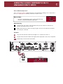
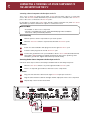
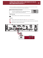
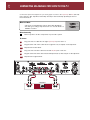
P 3 Preamplifier
Owner’s Guide
THANK YOU!
Congratulations and Thank You for Choosing Parasound
Your new Parasound P 3 Preamplifier presents the latest advancements in audio technology.
The P 3 is built to the strict quality and performance standards set by Parasound. We’re
proud to offer you this exceptional audio component that will bring many years of
enjoyment and dependability.
Here at Parasound, we design our products to perform to a higher level of flexibility
and sonic performance than you may have expected. We encourage you to read this
entire manual to learn all the features and capabilities of your new Halo P 3 Preamplifier.
If you’re eager to get up and running right away, simply follow the basic step-by-step
instructions to connect and operate the P 3. If you want to learn about some of the
technical and design aspects of your P 3, refer to the Technically Speaking and Design
Overview sections in the back of the manual. If you run into difficulties, the Troubleshooting
Guide should help you quickly remedy the problem.
We appreciate you taking the time to read these instructions and thank you for selecting
Parasound for your listening pleasure.
The Parasound Staff
Keeping Records for Future Reference
Record the serial number located on the bottom of your P 3 below. You should also note
your Parasound Dealer’s name and phone number. We recommend that you keep your
purchase receipt with this manual and store them both in a safe place. You may need to
refer to this information sometime in the future.
Parasound P 3 Preamplifier Serial #: __________________
Parasound Dealer: ____________________________________
Phone Number:_______________________________________
Date of Purchase: _____________________________________
YOU SHOULD KNOW
There is no Parasound warranty for this unit if it was not purchased from an Authorized
Parasound Dealer. Investigate any warranty claims made by unauthorized dealers very
carefully as you will need to depend entirely upon the dealer, and NOT upon Parasound.
Unauthorized dealers may lack the capability to arrange repairs of Parasound equipment.
Authorized Parasound Dealers are listed at www.parasound.com or you can call 415-397-7100
between 8:30 AM and 4:30 PM Pacific time.
A missing or tampered serial number could indicate that this unit was stolen or sold by an
unauthorized dealer. You should return it to your dealer immediately for replacement or a
full refund.
TABLE OF CONTENTS
P 3 Preamplifier
1
UNPACKING AND PLACEMENT GUIDELINES FOR THE P 3
__________________________________________________________________________________________
2
CONNECTING A SOURCE COMPONENT TO THE BALANCED DIRECT 1 INPUTS ON THE P 3
__________________________________________________________________________________________
3
CONNECTING A SOURCE COMPONENT TO THE UNBALANCED DIRECT 1 INPUTS ON THE P 3
__________________________________________________________________________________________
4
CONNECTING A SOURCE COMPONENT TO THE P 3 UNBALANCED DIRECT 2 INPUTS
__________________________________________________________________________________________
5
CONNECTING A TURNTABLE OR OTHER COMPONENT TO THE AUX INPUTS ON THE P 3
__________________________________________________________________________________________
6
CONNECTING OTHER SOURCE COMPONENTS TO THE CD AND TUNER INPUTS ON THE P 3
__________________________________________________________________________________________
7
CONNECTING AN ANALOG TAPE DECK TO THE P 3
__________________________________________________________________________________________
8
CONNECTING AN EXTERNAL SIGNAL PROCESSING COMPONENT TO THE P 3
EXTERNAL LOOP JACKS
__________________________________________________________________________________________
9
CONNECTING THE P3 TO THE BALANCED INPUTS ON YOUR POWER AMPLIFIER
__________________________________________________________________________________________
10
CONNECTING THE P 3 TO THE UNBALANCED INPUTS ON YOUR POWER AMPLIFIER
__________________________________________________________________________________________
11
CONNECTING AN INFRARED REPEATER SYSTEM TO THE P 3
__________________________________________________________________________________________
12
TURNING ON THE P 3 WITH AN EXTERNAL TRIGGER VOLTAGE
__________________________________________________________________________________________
13
TRIGGERING ON ANOTHER COMPONENT FROM THE P 3’S TRIGGER OUTPUT JACK
__________________________________________________________________________________________
14
RS232 CONTROL
__________________________________________________________________________________________
15
CONNECTING THE P 3 AC POWER CORD
__________________________________________________________________________________________
16
OPERATING YOUR P 3
__________________________________________________________________________________________
19
FRONT PANEL AND REMOTE CONTROL
__________________________________________________________________________________________
20
TROUBLESHOOTING GUIDE
__________________________________________________________________________________________
SERVICING YOUR P 3
21
__________________________________________________________________________________________
22
TECHNICALLY SPEAKING
__________________________________________________________________________________________
24
PARASOUND P 3 DESIGN OVERVIEW
__________________________________________________________________________________________
25
PARASOUND P 3 SPECIFICATIONS
__________________________________________________________________________________________
1
UNPACKING AND PLACEMENT GUIDELINES FOR THE P 3
Unpacking Your P 3
Carefully unpack your P 3 from the shipping carton and remove all the enclosed accessories:
• Remote control with two AAA batteries
• Detachable AC cord
• Two Trigger control wires with a 2.5 mm sub-mini plug on each end.
While you are unpacking your new preamplifier, inspect it thoroughly for possible shipping
damage. If you see any, contact your Parasound dealer right away. Be sure to save and store
both the inner and outer cartons and packing inserts for possible future transport. To save room
for storage, you can cut the seams on the bottom of the cartons and flatten them.
Placement Guidelines for Your P 3
For trouble-free operation and long-term reliability, follow the simple guidelines below to help
decide where to locate your P 3 in your system.
• Place the P 3 on a separate shelf that will adequately support its weight.
• Keep it away from heat sources such as air ducts or radiators.
• Leave at least 1” of space on all sides and the top. This helps facilitate passive
heat dissipation.
Rack Mounting Your Parasound P 3
If you plan to mount the P 3 into a standard 19” wide equipment rack, you will need to purchase
the optional Parasound HRA 2 Rack Mount Adapter. With its four feet removed, the P 3 chassis
and front panel height occupies two rack spaces (3-1/2” or 88mm). When mounting equipment
below the P 3, you will also need to allow about 1/8” below the unit for the bottom chassis
screws. A standard single rack space is 1-3/4” high in a 19” wide equipment rack. This
measurement standard was developed by the EIA (Electronic Industries Association) so
manufacturers of electronic components and equipment racks could build products in
standardized heights that would fit in a uniform space. Please call your Parasound dealer or call
directly to Parasound Technical Services if you need additional advice about rack mounting the P 3.
CONNECTING A SOURCE COMPONENT TO THE BALANCED
DIRECT 1 INPUTS ON THE P 3
2
Left and Right Direct 1 Input Jacks
Balanced connections will give you the best sound. If your source components have balanced
XLR output jacks, we recommend that you connect them to these inputs. Refer to the Balanced
and Unbalanced Lines in the Technically Speaking section for additional information about
why we recommend using balanced lines.
What You’ll Need:
Male
• One pair of balanced interconnect cables with XLR connectors
• An audio source component with balanced output connectors
Female
XLR Connectors
Before Connecting
Leave the P 3’s AC cord disconnected until you have made all connections to prevent
any surprise burst of sound.
Make sure that all your cables are long enough so they are not strained or stretched
once they are connected.
Make sure the Direct 1 Select switch on the P 3 is in its balanced (left) position.
To Connect
1
Plug the male end of one of the balanced cables into the right Balanced Direct 1 input
jack on the P 3
2
Plug the female end of this cable into the right channel output connector on your
source component.
3 &4
Repeat steps 1 and 2 for the left channel.
YOU SHOULD KNOW
Balanced XLR Jacks and Their Pin Configuration
The balanced inputs of the P 3 use XLR jacks that conform to the industry standard of: Pin 1:
Ground, Pin 2: Positive (+), Pin 3: Negative (--). The balanced outputs on some components
use terminals with 3 screws instead of XLR jacks. These are compatible with the P 3 as long
as you match the bare wires to the corresponding pins on the XLR plug: + to pin 2, - to pin 3,
and Ground to pin 1.
Interconnect Cables and Their Color Codes
Common color codes for input and output jacks are red for right and white for left. Match the
colors at the outputs from your preamplifier or surround controller to the inputs on your P 3
so you’ll always hear the channels in their intended position.
3
CONNECTING A SOURCE COMPONENT TO THE UNBALANCED
DIRECT 1 INPUTS ON THE P 3
Left and Right Direct 1 Unbalanced Inputs
If your best-sounding audio source component has only unbalanced RCA output jacks,
connect them to the P 3 unbalanced Direct 1 input jacks.
What You’ll Need:
Left
• One pair of shielded interconnect cables with RCA plugs
• A source component with RCA output jacks
Right
RCA Plugs
Before Connecting
Leave the P 3’s AC cord disconnected until you have made all connections to prevent
any surprise burst of sound.
Make sure that all your cables are long enough so they are not strained or stretched
once they are connected.
Make sure the Direct 1 Select switch on the P 3 is in its unbalanced (right) position.
To Connect
1
Plug one end of the first cable into the right Direct 1 input jack on the P 3.
2
Plug the other end of this cable into the right channel output jack on the source component.
3 &4
Repeat steps 1 and 2 for the left channel.
CAUTION
3
1
2
4
COMPONENTS
Right
Left
OUTPUTS
CD PLAYER
TAPE DECK
FM
87
AM 510
?
TUNER
AUX
YOU SHOULD KNOW
To achieve the purest sound reproduction, the tone control and record outputs don’t function
for Direct Inputs 1 and 2. Therefore, you cannot alter the tone or make recordings from
components that are connected to the Direct inputs.
CONNECTING A SOURCE COMPONENT TO THE P 3
UNBALANCED DIRECT 2 INPUTS
4
Direct 2 Unbalanced Input Jacks
The P 3 Unbalanced Direct 2 input jacks are for your next-best-sounding source component if
the Direct 1 input jacks are already connected to another source.
What You’ll Need:
Left
• One pair of shielded interconnect cables with RCA plugs
• A source component with RCA output jacks
Right
RCA Plugs
Before Connecting
Leave the AC cord of the P 3 disconnected until you have made all connections to
prevent any surprise burst of sound.
Make sure that all your cables are long enough so they are not strained or stretched
once they are connected.
To Connect
1
Plug one end of the first cable into the right Direct 2 input jack on the P 3.
2
Plug the other end of this cable into the right channel output jack on the source component.
3 &4
Repeat steps 1 and 2 for the left channel.
CAUTION
3
1
2
4
COMPONENTS
Right
Left
OUTPUTS
CD PLAYER
TAPE DECK
FM
87
AM 510
?
TUNER
AUX
5
CONNECTING A TURNTABLE OR OTHER COMPONENT TO
THE AUX INPUTS ON THE P 3
Connecting a Source Component to the Aux Inputs on the P 3
The P 3 has a single Aux input, but two pairs of Aux jacks for either a phono or a line level
source. The Aux Select switch determines if you’ll hear the source connected to the Aux-Phono
jacks or the source connected to the Aux-Line jacks.
It’s possible to use both pairs of Aux jacks, but this requires using the rear panel Aux Select
switch when you want to switch from a phono to a line level source.
What You’ll Need:
• A turntable or other source component
• One pair of shielded interconnect cables with RCA plugs. Most turntables
have these cables permanently attached
Before Connecting
Remove power to all the components in your audio system.
Move the Aux Select switch so it points left toward the Aux-Phono jacks.
To Connect
1
Insert one of the turntable cable plugs into the P 3 right Aux-Phono jack.
2
Insert the other plug into the P 3 left Aux-Phono jack.
3 &4
Connect the ground wire from your turntable to the P 3 Phono-GND (Ground) terminal.
Unscrew the GND terminal post slightly and insert the bare end or spade lug of the
turntable’s ground wire. Tighten the terminal post down firmly.
Connecting Another Source Component to the Aux Inputs on the P 3
Follow the same steps as when connecting a turntable with the following exceptions:
Move the Aux Select switch so it points right toward the Aux-Line jacks.
There is no separate ground wire for line-level source components.
To Connect
1
Plug one end of the first cable into the right Aux-Line input jack on the P 3.
2
Plug the other end of this cable into the right channel output jack on the source component.
3 &4
Repeat steps 1 and 2 for the left channel.
CAUTION
2
3
1
4
Right
Left
OUTPUTS
TURNTABLE
CONNECTING OTHER SOURCE COMPONENTS TO THE CD
AND TUNER INPUTS ON THE P 3
6
Connect the outputs of your CD player, tuner, or any other line level source to the CD and
Tuner jacks. All of the line level inputs are electrically identical.
What You’ll Need For Each Input Connection:
Left
• One pair of shielded interconnect cables with RCA plugs
• A source component with RCA output jacks
Right
RCA Plugs
Before Connecting
Remove power to all the components in your audio system.
To Connect
1
Plug one end of the first cable into the right CD (or Tuner) jack on the P 3.
2
Plug the other end of this cable into the right channel output jack of the source component.
3 &4
Repeat steps 1 and 2 for the left channel.
CAUTION
3
1
2
4
COMPONENTS
Right
FM
87
AM 510
Left
OUTPUTS
CD PLAYER
TUNER
7
CONNECTING AN ANALOG TAPE DECK TO THE P 3
Connect the input and output from your analog tape recorder to the Tape Play and Rec (Record)
jacks of the P 3. See Tape Record and Play Circuitry in the Technically Speaking section for
more information.
What You’ll Need:
Left
• Two pairs of shielded interconnect cables with RCA plugs
• An analog recording component such as a cassette deck or a
MiniDisc recorder
Right
RCA Plugs
Before Connecting
Remove power to all the components in your audio system.
To Connect
1
Plug one end of a cable into the right Tape Play/In jack on the P 3.
2
Plug the other end of this cable into the right line out (or Output) on the tape deck.
3&4
Repeat for the left channel.
5
Plug one end of another cable into the left Rec/Out jack on the P 3.
6
Plug the other end of this cable into the left Tape Rec/In (or Record) jack on the tape deck.
7&8
Repeat for the right channel.
CAUTION
3
5
1
7
COMPONENTS
4
8
2
Right
Left
6
Right
OUTPUTS
Left
INPUTS
TAPE DECK
CONNECTING AN EXTERNAL SIGNAL PROCESSING
COMPONENT TO THE P 3 EXTERNAL LOOP JACKS
8
You can connect signal-processing equipment such as a frequency-shaping equalizer into the signal
path of the P 3 via its External Loop Connections. See External Loop In/Out Connections in the
Technically Speaking section for more information.
What You’ll Need:
Left
• Two pairs of shielded interconnect cables with RCA plugs
• A signal-processing component
Right
RCA Plugs
Before Connecting
Remove power to all the components in your audio system.
Remove the two U-shaped metal jumpers that are already inserted into the External
Loop Out and External Loop In jacks. Make sure to save these jumpers and put them
where you can locate them if you need them in the future.
To Connect
1
Plug a cable into the Left Loop/Out jack on the P 3.
2
Plug the other end of this cable into the left input jack on the signal-processing component.
3&4
Repeat for the right channel.
5
Plug a third cable into the Left Loop/In jack on the P 3.
6
Plug the other end of this cable into the left output jack on the signal-processing component.
7&8
Repeat for the right channel.
CAUTION
1
5
3
7
COMPONENTS
2
8
4
Right
Left
Right
INPUTS
6
Left
OUTPUTS
SIGNAL PROCESSOR
YOU SHOULD KNOW
Your system cannot function if the U-shaped jumpers are removed and a component is not
connected to the P3 Loop/Out and Loop/In jacks. If you misplace the jumpers, you can substitute
a pair of shielded cables to reconnect the P3 Loop/Out and Loop/In jacks for each channel.
9
CONNECTING THE P 3 TO THE BALANCED INPUTS ON
YOUR POWER AMPLIFIER
For best sound performance, use the P 3 Balanced Line Output connections if your power
amplifier is equipped with balanced inputs.
What You’ll Need:
Male
• One pair of balanced interconnect cables with XLR plugs
• An amplifier with balanced XLR input jacks
Female
XLR Connectors
Before Connecting
Leave the AC cord disconnected until you have made all connections to prevent any
surprise burst of sound.
Make sure that all your cables are long enough so they are not strained or stretched
once they are connected.
To Connect
1
Plug the female end of one of the balanced interconnect cables into the P 3’s right
channel Balanced Line Output 2 jack.
2
Plug the male end of this cable into the balanced right channel input jack on your
power amplifier.
3 &4
Repeat steps 1 and 2 for the left channel.
CAUTION
3
1
Right
2
Left
POWER AMPLIFIER
4
INPUTS
YOU SHOULD KNOW
Balanced XLR Jacks and Their Pin Configuration
The balanced outputs of the P 3 use XLR jacks that conform to the industry standard of: Pin 1:
Ground, Pin 2: Positive (+), Pin 3: Negative (--). The balanced inputs on some components use
terminals with 3 screws instead of XLR jacks. These are compatible with the P 3 as long as
you match the bare wires to the corresponding pins on the XLR plug: + to pin 2, - to pin 3, and
Ground to pin 1.
Interconnect Cables and Their Color Codes
Common color codes for input and output jacks are red for right and white for left. Match the
colors at the outputs from your preamplifier or surround controller to the inputs on your P 3
so you’ll always hear the channels in their intended position.
CONNECTING THE P 3 TO THE UNBALANCED INPUTS ON
YOUR POWER AMPLIFIER
10
Use these outputs if your power amplifier does not have balanced input connectors or if you
prefer to use unbalanced connections.
What You’ll Need:
Left
• One pair of shielded interconnect cables with RCA jacks
• A power amplifier with unbalanced input jacks
Right
RCA Plugs
Before Connecting
Remove power to all the components in your audio system.
To Connect
1
Plug one end of the first cable into the right channel Line Output 1 jack on the P 3.
2
Plug the other end of this cable to the right channel input jack on your power amplifier.
3 &4
Repeat steps 1 and 2 for the left channel.
CAUTION
1
Right
2
POWER AMPLIFIER
Left
INPUTS
4
3
11
CONNECTING AN INFRARED REPEATER SYSTEM TO THE P 3
The External Remote Input jack is for a wired infrared repeater system or system controller. It
eliminates the need for a stick-on front panel IR flasher. There is also a Loop Out jack to loop
or “daisy chain” to an additional infrared remote-controlled component.
What You’ll Need:
•
•
•
•
An infrared receiving eye
A power supply for the IR system
A connecting block from the external IR system’s manufacturer
One cable with a 1/8” mini-plug on each end
Before Connecting
Remove power to all the components in your audio system.
To Connect
1
Plug the receiving eye into the input on the connecting block.
2
Plug the power supply into the connecting block.
3
Push one of the 1/8” mini-plugs into the connecting block.
4
Push the plug at the other end of this cable into the External Remote In jack on the P 3.
5
Plug an IR flasher or other IR repeater into the P 3’s External Remote Loop Out jack to
control another component if desired.
CAUTION
4
5
IR CONNECTING BLOCK.
1
3
Input
Output
2
YOU SHOULD KNOW
Some IR systems may vary slightly from this connection. Refer to the installation manual of
your repeater system for more information.
TURNING ON THE P 3 WITH AN EXTERNAL TRIGGER VOLTAGE
The P 3 can be turned on automatically when a trigger voltage is received from an external DC
voltage source such as a system controller.
What You’ll Need:
• A trigger cable with 2.5 mm sub-mini plugs (provided)
• A component with an external +9Vdc to +12Vdc trigger
voltage
2.5 mm sub-mini plug
Before Connecting
Remove power to all the components in your audio system.
To Connect
1
Plug one end of this cable into the 12V Trigger Input jack of the P 3.
2
Plug the other end into the component with an external DC trigger voltage.
CAUTION
1
2
Output
SYSTEM CONTROLLER
YOU SHOULD KNOW
If the component you want to use to control your P 3 doesn’t have a 2.5 mm trigger output
jack, you can cut off one plug and terminate the end of the wire. The lead with the red stripe
is positive and the lead without a stripe is negative.
You cannot automatically turn on the P 3 by applying AC power to the unit. Therefore, the P 3
will not turn on automatically if it is connected to a switched AC outlet.
12
13
TRIGGERING ON ANOTHER COMPONENT FROM THE P 3’S
TRIGGER OUTPUT JACK
The 12V Trigger Output jack generates its own +12 Vdc voltage whenever the P 3 is turned on
so it can trigger other components such as a Parasound power amplifier. This output will
provide up to 200 mA of current to trigger an external component.
What You’ll Need:
• A second trigger cable with 2.5 mm sub-mini plugs (provided)
• A component that can be triggered with an external +9 Vdc to
+12 Vdc trigger voltage
2.5 mm sub-mini plug
Before Connecting
Remove power to all the components in your audio system.
To Connect
1
Connect one end of this cable to the 12V Trigger Output jack on the P 3.
2
Connect the other end to the component that you want to trigger.
CAUTION
1
2
Input
TRIGGERED COMPONENT
YOU SHOULD KNOW
If the component you want your P 3 to control doesn't have a 2.5 mm trigger input jack, you.,
you can cut off one plug and terminate the end of the wire. The lead with the red stripe is
positive and the lead without a stripe is negative.
RS232 CONTROL
14
The P 3 External Control connector is used only if you have a computer-based system controller.
The P 3 is compatible with most system controllers. RS232 codes for Parasound units can be
downloaded from www.parasound.com.
Connecting a Controller to the RS232 Port of the P 3
What You’ll Need:
• A computer-based control system with RS232 serial output
• An RS232 serial cable with a DB9 connector. The pin
configuration is: Pin 2-transmit, Pin 3-receive, Pin 5-ground
RS232 Connector
Before Connecting
Remove power to all the components in your audio system.
To Connect
1
Connect the RS232 cable to the output of the computer-based control system.
2
Plug the RS232 cable into the RS232 Control connector on the P 3.
CAUTION
2
1
COMPUTER CONTROL
YOU SHOULD KNOW
If your system controller doesn’t use a DB9 connector, the pin configuration of its connector
must correspond to: Pin 2 transmit, Pin 3 receive, Pin 5 ground.
15
CONNECTING THE P 3 AC POWER CORD
AC Power Connections
We recommend plugging your P 3 into the same AC outlet or power strip used for your
accompanying audio components, especially the power amplifier and source components.
What You’ll Need:
• An IEC 65 AC Cord (provided)
• An AC outlet or power strip within reach of the AC cord
Before Connecting
Remove power to all the components in your audio system.
To Connect
1
Plug the female end of the AC cord into the AC receptacle on the rear of the P 3.
2
Plug the male end of the AC cord into an active AC outlet.
1
2
AC Voltage Selection Switch
The P 3 can operate on either 110-120 Vac or 220-240 Vac operation. When you
purchased your P 3, its rear panel Voltage Selector switch was already set for
the proper voltage in your area. Nevertheless, it’s wise to double-check it
before plugging into an AC outlet.
If you move to a location with a different line voltage, you can easily convert the P 3.
For 110-120 Vac Operation: Remove the lock-out bracket with a phillips
screwdriver. Next, slide the switch toward the left until the groove on the
switch lines up with 115/60Hz. Replace lock-out bracket.
For 220-240 Vac Operation: Remove the lock-out bracket with a phillips
screwdriver. Next, slide the switch toward the left until the groove on the
switch lines up with 230V/50Hz. Replace lock-out bracket.
If you’re unsure about the correct setting for your region, please consult your
Parasound dealer or a qualified service technician.
OPERATING YOUR P 3
16
See page 19 for P 3 Front Panel and Remote Control layout
Turning the P 3 On and Off
You can turn the P 3 on and off with the On-Off button on its front panel, with the On
and Off buttons on its remote control handset, or with an external DC source.
Turning On the P 3
Press either the On-Off Button on the front panel or the On button on the remote control.
Turning Off the P 3
Press either the On-Off Button on the front panel or the Off button on the remote control.
YOU SHOULD KNOW
Even when the P 3 is turned off, there is a faint glow behind its On-Off button and its P logo
badge to indicate that AC power is present. When you turn it on, the P badge and the glow
behind the On-Off button brighten, and the front panel displays the previously selected input
and volume.
Adjusting the Volume Level
You can control the overall volume
level of the P 3 in 1 dB steps with the large knob on
V
the front panel or the Volume
and V buttons on the remote control.
To increase
V volume, turn the volume control knob in a clockwise direction or press the
Volume
button on the remote control.
To decrease volume, turn the volume control knob in a counter-clockwise direction or
press the Volume V button on the remote control.
YOU SHOULD KNOW
P 3 Volume Indication
The P 3 displays volume from 00 to 80. These numbers do not correspond to reference voltages.
Muting the Main Outputs
You can mute the output of the P 3 whenever you want to quickly interrupt listening
and return to the same volume setting. The Mute button reduces volume to zero much
faster than turning the knob on the front panel or holding the Volume V button on the
remote control.
Muting the Output of the P 3
Press the Mute button on the remote control. MUTE will flash in the front panel display.
The small red indicator at the lower right of the front panel will illuminate red.
Taking the P 3 Out Of the Mute Mode
Press the Mute button on the remote control. You will
V also defeat muting by adjusting
the volume control knob or by pressing the Volume
or V buttons on the remote handset.
YOU SHOULD KNOW
When you press the Mute button on the remote control, the signal is muted at the Line Out,
Phones, and Loop Output jacks, but not at the Tape Rec/Out jacks. You will automatically turn
off mute if you press the Mute button a second time or change the volume level.
17
OPERATING YOUR P 3 continued
See page 19 for P 3 Front Panel and Remote Control layout
Selecting the Input Source
You can select the input source by repeatedly pressing the Source button on the front
panel until the desired source name appears in the status display. You can also select
the desired source directly with the Source select buttons on the remote control.
The Source buttons on the remote control correspond to the following:
Remote Control Button Input
1
Direct 1
2
Direct 2
3
Aux (line or phono selected at rear panel)
4
Tuner
5
CD
6
Tape
Selecting the Input Source on the P 3
1
Press the front panel Source button until the desired input source is selected. You can
also press the Source buttons on the remote control.
Adjusting the Balance Level
You can adjust the balance of the P 3 with the < Balance > buttons on the front panel.
Each press of a button in either direction increases the relative balance in 2 dB increments
Adjusting Balance toward the Right Channel
1
Press the Balance > button once to show the present balance level in the display.
2
The next time you press the Balance > button it will change the balance.
3
Keep pressing the Balance > button until the desired balance is reached. Each time
you press the Balance > button, the right channel level will increase by 2 dB.
Adjusting Balance toward the Left Channel
4
Press the < Balance button once to show the present balance level in the display.
5
The next time you press the < Balance button it will change the balance.
6
Keep pressing the < Balance button until the desired balance is reached. Each time
you press the < Balance button, the left channel level will increase by 2 dB.
OPERATING YOUR P 3 continued
See page 19 for P 3 Front Panel and Remote Control layout
Adjusting Bass and Treble Tone
Tone Button
Pressing the Tone button on the front panel or remote control turns on the tone
display. The illumination around the Bass and Treble buttons will also brighten. After
pressing the Tone button, you have about five seconds to make adjustments.
< Bass > Buttons
1
Press the Tone button once to display the present bass boost or cut.
2
Keep pressing the Bass < or > button until you reach the desired bass level.
3
After about 5 seconds, the display will revert to show source and volume level.
< Treble > Buttons
1
Press the Tone button once to display the present treble boost or cut.
2
Keep pressing the Treble < or > button until you reach the desired treble level.
3
After about 5 seconds, the display will revert to show the source and volume level.
Phones Jack
Connect your stereo headphones to this standard 1/8” jack. The outputs of the P 3
are still active when you connect a headphone.
YOU SHOULD KNOW
If you want to listen to the headphones with no music playing through your speakers, you will
need to turn off your power amplifier manually.
Remote Control Handset
The P 3 remote control handset controls the following functions from up to 25’
(8 meters) away:
On
Off
Volume increase
Volume decrease
Mute
Source Select
Tone on/off (but not actual tone adjustment)
For your convenience, it also controls the Parasound T 3 Tuner.
The remote uses two standard AAA batteries that are included. Make sure you insert
the batteries in the direction indicated on the molded battery compartment. When the
batteries wear out, please recycle them and replace them only with alkaline type batteries.
18
P 3 FRONT PANEL AND REMOTE CONTROL
19
1
2
3
4
15
5
14
6
7
13
8
9
12
11
P 3 - T 3 Remote Buttons
Controls
1. On,Off
2. Tone On-Off
3. Mute On-Off
4. Source Select
5. Preset < >
6. Tuning < >
7. FM-AM Select
8. Tuner Presets
9. Enter Frequency
10. Memory & Automemory
11. Mono Select
12. Radio Data System
13. Seek < >
14. Manual < >
15. Volume Adjust
P
P
P
P
T
T
T
T
T
T
T
T
T
T
P
3&T3
3
3
3
3
3
3
3
3
3
3
3
3
3
3
10
10
9
1
2
3
4
7
5
P 3 Front Panel
1. Phones Jack
2. On-Off
3. Source Select
4. Bass Adjust
5. Tone Engage
6. Balance Controls
7. Treble Adjust
8. Mute Indicator
9. Volume Control
10. Display Window
6
8
TROUBLESHOOTING GUIDE
Your Parasound P 3 Preamplifier requires no periodic maintenance and has no user-serviceable
parts inside. To avoid the risk of electric shock, do not remove the top cover. The P 3’s
exterior can easily be cleaned with a soft cloth pre-moistened only with a few drops of
water or glass cleaner.
Main Power Fuse
If this fuse blows, please contact Parasound Technical Service for further advice.
TROUBLE
No power
P 3 will not turn on with
DC trigger voltage
Power but no sound
Distorted sound through
speakers.
Hum and/or buzz through
speakers
PROBABLE CAUSE
Power cord is disconnected
Voltage selector switch is in the
wrong position
AC fuse is blown
DC trigger source wired with reverse
polarity or voltage too low
Volume control turned down
Bad connection to power amplifier
External Loop jumpers are missing
P 3 is muted
REMEDY
Connect power cord
Make sure the Voltage selector switch is in the
correct position for your region
Replace fuse with one of the same value
Check polarity of the DC trigger source with
a voltmeter
Increase the volume control setting
Check the output connections
Replace External Loop jumpers
Press Mute button or adjust the Volume knob
or remote buttons to unmute the P 3
Damaged speaker
Exchange the left and right speaker cables.
If the same speaker is distorted, the speaker is
damaged. If not, the problem may be with your
power amplifier or further up the signal path
Problem with the power amplifier or Exchange the left and right P 3 output cables.
source component
If distortion stays in the same channel, the
problem is after the preamplifier
The P 3 Balance is adjusted all the Re-adjust with the Balance buttons
way to the left or right
Ground loop from cable TV
Move the ground switch on the power amplifier
to its lift position. Install a cable isolation device
such as the Xantech 634 Ground Breaker.
www.xantech.com
Ground loop between the P 3 and
Move the ground switch on the power amplifier
power amplifier
to its lift position.
Ground loop within equipment rack Install nylon shoulder washers on both sides of
the rack-mounted panels of all equipment to
prevent the P 3 from making any metal-to-metal
contact with the rack
Other ground loop
Contact Parasound Technical Service
20
21
SERVICING YOUR P 3
If All Else Fails –Call Us for Help
Call your Parasound dealer or Parasound’s Technical Service Department toll free at
1-866-770-TECH (8324). We can often solve the problem with simple diagnostic tests you can
perform yourself. If we determine that your P 3 will need further inspection or servicing, we will:
a) refer you to an authorized Parasound repair center near you, or
b) authorize return of the unit to us and advise you of the correct procedure.
Procedure for Returning Your P 3 to Parasound for Service
If Parasound determines that you should send your P 3 to Parasound, you will be given a Return
Authorization (RA) number. This RA number must be clearly marked on the outer carton only.
IMPORTANT: Enclose a copy of your original purchase receipt. A unit is eligible for warranty
repair ONLY when the purchase receipt shows that the unit was purchased from an Authorized
Parasound Dealer. A unit obtained through unauthorized channels is not eligible for warranty
repair. Parasound is not responsible for any sellers’ misrepresentations about our warranties or
other service policies.
We do not accept any of the following:
Units with collect shipping charges
Units without a valid RA number
Units without a suitable shipping carton
Units for which we see or hear evidence of improper packing
For a non-warranty repair, contact us for an estimate of the repair charges before you ship the
unit to us. The same packing and Return Authorization number procedures apply.
Important Notice - Shipping the P 3
Before shipping the unit to Parasound, you MUST re-pack the unit into its fitted molded foam
insert sandwich and its original carton. If you do not have the original packing cartons and foam
inserts, call us for new packing materials that we can provide to you for a nominal charge. Use of
any other carton and packing materials will probably result in shipping damage, and refusal of
the unit. Common carriers such as UPS seldom pay claims for damage incurred during shipment
when a product is surrounded only with Styrofoam “peanuts” or otherwise improperly packed.
We cannot stress enough the importance of properly packing your P 3. Shipping damage
resulting from inadequate packing can cost you a lot of money and significantly increase the
time required for repair.
Ship the unit with adequate insurance. After repair under warranty, the unit will be returned to
you via prepaid UPS within the continental United States.
TECHNICALLY SPEAKING
22
Balanced and Unbalanced Input Lines
Direct Inputs
Recording and broadcast studios use balanced
connections almost exclusively because of their
inherent ability to reject noise and hum, assuring the
best sound. Certain high quality preamplifiers and
surround controllers built for residential use utilize
balanced connections with XLR jacks for the same
reasons. The P 3’s balanced outputs enable you to
take full advantage of the inherent noise rejection
capability and superior sound quality of Parasound
Halo power amplifiers.
The P 3 direct inputs have the shortest signal paths
with the fewest parts from the input to the output to
avoid any contamination from collateral tone control
or record output circuits. As a result, you can’t alter
tone or make recordings from components that are
connected to Direct Inputs 1 or 2.
Unbalanced connections with RCA jacks are found on
all home audio equipment. RCA jacks and twoconductor wires are less costly than the additional
circuitry, higher priced XLR connectors and threeconductor wiring required for balanced connections.
In an unbalanced line, the positive audio signal
appears at the center pin of the RCA jack and the
negative signal on the outer shield wire, which also
functions as the ground connection. Unbalanced
interconnect cables are vulnerable to hum from an AC
line, or other noise, such as RFI (Radio Frequency
Interference), which can be reproduced through your
loudspeakers. Since the unbalanced line’s ground
also carries the audio signal, there is no way for the
connected amplifier or preamplifier to distinguish
between the audio signals you want and unwanted
noise emanating from external sources.
Balanced lines are superior because they utilize
separate conductors for audio and ground: two inner
conductors carry the positive and negative audio
signal, and a third outer wire connects the grounds
and also shields the two signal conductors. When the
positive and negative signals appear at the
component receiving the signal they are equal, but
180 degrees out of phase with each other with respect
to ground. To send and receive balanced signals
requires special differential circuitry.
A differential input circuit amplifies only the
difference between the positive and negative signals.
For example, when a 1 Volt signal arrives at a
balanced input stage, the differential input “sees” a
positive 1 Volt minus a negative 1 Volt, or 2 Volts total.
External hum and noise that somehow get into a
balanced line is common to both its positive and
negative conductors with respect to ground.
Therefore, it’s canceled, or rejected, by the differential
input circuit.
This phenomenon of rejecting noise signals common to
both positive and negative conductors is called
common-mode rejection. Differential inputs are
specified according to how well they reject signals
common to both conductors. This is measured in dB and
is called the common mode rejection ratio or CMRR.
External Loop In / Out Connections
The left and right channel External Loop In/Out jacks
come from the factory with jumpers installed. When
these jumpers are removed, you can "insert" signalprocessing components into the internal signal path
of the P 3. This includes signal processors such as
surround decoders, equalizers, and spatial
enhancers. The External Loop also lets you patch in a
second audio record/playback system such as
computer-based CD-R, CD-RW, and MP 3 burning and
monitoring components. You can also use the
External Loop to add in sound effects, narration, or
music on videotaped movies.
Output Connections
There are two pairs of output jacks on the rear panel
of your P 3, one balanced pair and one unbalanced
pair. When a source is playing, both outputs are
active. You can connect both output pairs
simultaneously to two amplifiers if you wish.
Balance
You can change the balance a maximum of 12 dB in
either direction. Usually, you should not need to
change the balance level from its 0 dB middle
position, but if your listening area is closer to one
speaker or the other, you can compensate for this
with the balance control so one speaker does not
sound louder than the other does.
Balanced Output Connections
Use the balanced output to connect your P 3 to a
power amplifier with balanced inputs such as the
Parasound Halo Series amplifiers. Like the Balanced
Inputs, the Direct Balanced XLR inputs provide the
highest-quality audio transmission of the P 3's
outputs. As mentioned earlier, balanced circuits
provide superior hum and noise cancellation and can
even eliminate hum created by ground loops,
especially in long wire runs.
Bass and Treble Level Controls and Tone Button
The bass and treble controls offer adjustment of
overall tonal balance. The Bass controls allow you to
boost or cut low frequencies +/- 10 dB in 2 dB steps.
The Treble controls allow you to boost or cut high
frequencies +/- 10 dB in 2 dB steps. To preserve sonic
clarity, use these controls sparingly and only for
recordings that sound better with them. You will find
that very slight adjustments can add a degree of
warmth, richness, clarity and airiness. However,
greater adjustments may obscure musical detail, and
23
TECHNICALLY SPEAKING continued
even risk overloading your speakers. You can only
adjust the bass and treble controls on the front panel.
However, you can compare the sound with the tone
controls on or off by pressing the Tone button on the
front panel or remote control.
DC Trigger Input Jack
The P 3 can be turned on automatically when a trigger
voltage is received from an external source such as a
system controller. The DC Trigger circuit can be
activated with a DC voltage from between +9 Vdc to +
12 Vdc and requires only 0.2 mA of current to activate.
Use the provided gray color cable with 2.5 mm submini plugs to connect the output of the DC trigger
source to the P 3’s 12 V Trigger input. Depending on
the component used to trigger the P 3 on, you may
need to modify the DC trigger wire differently. To
trigger properly, the positive voltage must appear at
the tip of the 2.5 mm plug. The wire with the red stripe
corresponds to the positive connection.
Note: When a live DC source is connected to the P 3’s
12 V Trigger Input jack, you cannot turn the P 3 off
with its front panel On-Off button or remote control
handset Off button.
DC Trigger Output Jack
The P 3 generates its own +12 Vdc voltage at the 12 V
Trigger Out jack so you can trigger on other components.
External Remote Input and Loop Out
The External Remote input is for connection to a
wired infrared repeater system or system controller.
This input jack accepts a standard 1/8" (3.5 mm) twoconductor mini-plug with a positive tip and a negative
sleeve. Your Authorized Parasound Dealer or Custom
Installer can recommend a compatible infrared
repeater system for the P 3.
The External Remote circuit has a loop output so you
can connect an additional IR controlled component.
Front Panel Display
The display on the front panel indicates operational
status of the P 3 including:
• Source Selected
• Volume Level of both channels
• Muting status
Eliminating Hum and Buzz Caused by Ground Loops
Audible hum and buzzing noises in a system are
usually related to issues with the component
grounds. Ground (sometimes called common) is a
point of reference for voltages in virtually all audio
and video components. Ground is supposed to
remain at zero volts while the audio signal swings
positive (voltage above ground) and negative (voltage
below ground). If ground isn’t at zero, there can be an
audible 60 Hz hum (or 50 Hz hum in regions with 50
Hz AC). The harmonics of these frequencies (120 Hz,
240 Hz, 480 Hz or 100 Hz, 200 Hz, 400 Hz) may add
buzz in addition to the hum.
The ideal of zero voltage ground for all the
components in a system is practically impossible,
because some resistance between the ground points
of different components is inevitable. By keeping
components close together with their power cords
plugged into a common AC outlet or power strip,
you’ll avoid the problems created by resistance in the
house’s wiring.
Hum and buzz is also caused when unwanted voltage
flows through multiple component ground points
called ground loops. Here are three tips to avoid
ground loops:
1. Use balanced input lines with your Parasound P 3.
(See Balanced and Unbalanced Lines in this section).
2. When rack mounting, always use insulated
“shoulder” washers. These break the ground loops
caused by metal-to-metal contact between the rack,
the units, and their rack-mount bolts. Washers are
included in Parasound rack mount kits. Extras are
available from rack manufacturer Middle Atlantic
Products, www.middleatlantic.com.
3. Use the ground switch on your power amplifier to
eliminate most ground loops. This separates the
amplifier’s signal input ground from its chassis ground
to isolate unwanted voltage in the shields of the
unbalanced (RCA) interconnect cables. Be sure your
system installation is finished before you try moving
the ground switch from its “Normal” to its “Lift”
position.
Headphone Circuit
The P 3 includes a high-quality headphone amplifier.
It is suitable for headphones with an impedance of 8 Ω
or higher. The headphone jack accepts a standard
1/8” (3.5 mm) mini-jack. If your headphones have a
1/4” jack, you will need a stereo 1/4” jack-to-stereo
1/8” mini-plug adapter.
Tape Record and Play Circuitry
The Tape Play/In and Rec/Out jacks on the P 3 enable
you to connect a cassette deck or the analog input
and output of a MiniDisc or CD recorder. You can also
play back analog audio outputs from your computer’s
sound card or MP3 player.
If you don’t have a recording device, you can use the
P 3’s Tape Play/In jacks as an input for another line
level source component. The P 3 bass and treble
controls function only for playback, so you can’t use
them when making recordings.
PARASOUND P 3 DESIGN OVERVIEW
Parts Selection
Audio Circuit Path Topology
Every part within the P 3 is carefully chosen for its
accuracy and reliability. Metal film resistors with 1%
tolerance are selected for their precision and because
their values don’t drift as they heat up during
operation. Polypropylene and mica capacitors are
used extensively for their superior linearity and low
dielectric absorption. Semiconductors are selected for
superior performance in their specific roles in the
circuit. Gold has the best conductivity of any metal, so
we use high quality gold-plated input connectors and
speaker terminals. The double-sided circuit boards
are FR4 glass epoxy for long-term durability. The
chassis is made of heavy gauge steel to safely house
the internal circuitry. This attention to detail when
selecting parts makes the difference between a very
good preamplifier and an outstanding one.
Direct Inputs 1 and 2 of the Parasound P 3
preamplifier are selected by hermetically sealed
relays with gold contacts. The other inputs are
switched by a precision CMOS IC with outstanding
characteristics for signal overload, low distortion and
crosstalk, and wide frequency response. This
provides longer-term reliability than the mechanical
rotary selector switches used in most preamplifiers.
The P 3 also employs the newest Burr-Brown OPA
2134 integrated circuits with FET input stages for
audio gain functions in the audio signal path. They are
laser-trimmed for precision and boast incredibly low
noise and distortion specifications. We run the OPA
2134s at very high current to assure pure class A for
linear performance and musical characteristics,
without fatigue and harshness. The P 3 volume and
balance controls are high-precision analog volume
control ICs which provide very close level matching
between channels, far closer than is possible with a
manual or motor-driven mechanical potentiometer.
The Power Supply
The P 3 power supply begins with a large toroidal
power transformer that is chosen for its high
efficiency, low radiated hum, and high current rating.
Encapsulating the power transformer in an epoxyfilled steel canister assures ultra-quiet performance.
The audio signal path circuits and the
switching/control circuits have independent closely
regulated power supplies. This preserves the purity of
the audio signal by preventing interference between
the circuits. We also use a hand-made detachable
audiophile-grade AC cord to deliver the AC voltage to
the power transformer.
To create the DC voltage, we use high-speed rectifier
diodes and large-capacity Nichicon electrolytic filter
capacitors that are famous for low dielectric
absorption and Effective Series Resistance (ESR). Two
precision 6,800 uF filter capacitors are used for the
audio signal path B+ and B- rails, plus two 2,200 uF
capacitors for the control/switching circuitry. In
addition, these filter capacitors are bypassed with
polypropylene capacitors to help reduce AC ripple
and to eliminate noise and interference that is
generated in AC power lines from computers and
other appliances in the home.
Functionality
The P 3’s elegant front panel control and status
display make it easy to use. Its remote handset
provides convenient control over both the P 3 and the
matching Parasound T 3 Tuner. Separate On and Off
remote commands permit system programming for
unambiguous on/off status. Features that facilitate P 3
system integration include its RS232 interface for
more robust control than IR, wired external IR input
and loop out, and DC trigger input and output. These
make the P 3 as functional as it is great sounding.
24
25
PARASOUND P 3 SPECIFICATIONS
Frequency Response
5 Hz - 55 kHz, +0/-1 dB, full output
Maximum Input Level
10.5 V before clipping
Total Harmonic Distortion
< 0.01%, 1 kHz
< 0.03%, 20 kHz
Signal-to-Noise Ratio
Line inputs: > 92 dB, A-weighted, full output
> 84 dB, unweighted, full output
Phono input: >72 dB, ref. 5 mV input
IM Distortion
< 0.03%
Crosstalk
> 55 dB, 20 kHz
Maximum Output
> 8 V, before clipping
Tone Controls
Bass +/- 10 dB at 100 Hz
Treble +/- 10 dB at 10 kHz
Input Impedances
Line inputs: 30 kΩ
Tape/Play input: 30 kΩ
External Loop input: 30 kΩ
Phono input: 47 kΩ
Output Impedances
Main outputs: < 60 Ω
Tape/Rec output: < 60 Ω
External Loop output: < 60 Ω
Recommended power amplifier load:
> 600 Ω
Recommended headphone: > 8 Ω
Channel Level Matching
< 0.1 dB
Dimensions
Width: 17-1/4” (437 mm)
Panel Height: 3-1/2” (88 mm)
Total Height with feet: 4-1/8” (105 mm)
Total Height with rack adapter attached: 3-5/8”
Depth: 13-3/4” (350 mm)
Power Requirement
12 Watts
Net Weight
16 lb. (7.3 kg)
Shipping Weight
23 lb. (10.5 kg)
Input Sensitivity
Line inputs: 150 mV, ±5%
Phono input: 2 mV
Features and specifications subject to change
without notice.
© Parasound Products, Inc. 2002. V 1.1
Parasound Products, Inc. 950 Battery Street, San Francisco, CA 94111
415-397-7100 / Fax 415-397-0144 www.parasound.com