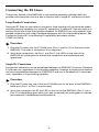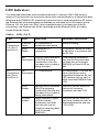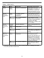
1
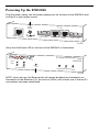
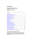
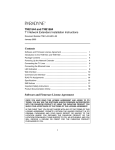
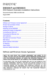
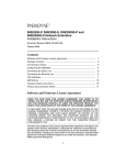
ENE2020-P and ENE2020-S 2-Port E1 Network Extenders Installation Instructions Document Number ENE2-A2-GN10-10 September 2005 Contents Software and Firmware License Agreement ................................................. 1 Product Documentation ................................................................................ 3 Warranty, Sales, Service, and Training Information ...................................... 3 Package Contents ......................................................................................... 3 Powering Up the ENE2020 ........................................................................... 4 Configuring the E1 Ports ............................................................................... 5 Connecting the E1 Lines ............................................................................... 8 Connecting the Ethernet Line ....................................................................... 9 LED Indicators .............................................................................................. 10 RJ45 Pin Assignments .................................................................................. 12 EMI Notices .................................................................................................. 13 Important Safety Instructions ........................................................................ 14 Software and Firmware License Agreement ONCE YOU HAVE READ THIS LICENSE AGREEMENT AND AGREE TO ITS TERMS, YOU MAY USE THE SOFTWARE AND/OR FIRMWARE INCORPORATED INTO THE PARADYNE PRODUCT. BY USING THE PARADYNE PRODUCT YOU SHOW YOUR ACCEPTANCE OF THE TERMS OF THIS LICENSE AGREEMENT. IN THE EVENT THAT YOU DO NOT AGREE WITH ANY OF THE TERMS OF THIS LICENSE AGREEMENT, PROMPTLY RETURN THE UNUSED PRODUCT IN ITS ORIGINAL PACKAGING AND YOUR SALES RECEIPT OR INVOICE TO THE LOCATION WHERE YOU OBTAINED THE PARADYNE PRODUCT OR THE LOCATION FROM WHICH IT WAS SHIPPED TO YOU, AS APPLICABLE, AND YOU WILL RECEIVE A REFUND OR CREDIT FOR THE PARADYNE PRODUCT PURCHASED BY YOU. The terms and conditions of this License Agreement (the “Agreement”) will apply to the software and/or firmware (individually or collectively the “Software”) incorporated into the Paradyne product (the “Product”) purchased by you and any derivatives obtained 1 from the Software, including any copy of either. If you have executed a separate written agreement covering the Software supplied to you under this purchase, such separate written agreement shall govern. Paradyne Corporation (“Paradyne”) grants to you, and you (“Licensee”) agree to accept a personal, non-transferable, non-exclusive, right (without the right to sublicense) to use the Software, solely as it is intended and solely as incorporated in the Product purchased from Paradyne or its authorized distributor or reseller under the following terms and conditions: 1. Ownership: The Software is the sole property of Paradyne and/or its licensors. The Licensee acquires no title, right or interest in the Software other than the license granted under this Agreement. 2. Licensee shall not use the Software in any country other than the country in which the Product was rightfully purchased except upon prior written notice to Paradyne and an agreement in writing to additional terms. 3. The Licensee shall not reverse engineer, decompile or disassemble the Software in whole or in part. 4. The Licensee shall not copy the Software except for a single archival copy. 5. Except for the Product warranty contained in the manual, the Software is provided “AS IS” and in its present state and condition and Paradyne makes no other warranty whatsoever with respect to the Product purchased by you. THIS AGREEMENT EXPRESSLY EXCLUDES ALL OTHER WARRANTIES, WHETHER EXPRESS OR IMPLIED, OR ORAL OR WRITTEN, INCLUDING WITHOUT LIMITATION: a. Any warranty that the Software is error-free, will operate uninterrupted in your operating environment, or is compatible with any equipment or software configurations; and b. ANY AND ALL IMPLIED WARRANTIES, INCLUDING WITHOUT LIMITATION IMPLIED WARRANTIES OF MERCHANTABILITY, FITNESS FOR A PARTICULAR PURPOSE AND NON-INFRINGEMENT. Some states or other jurisdictions do not allow the exclusion of implied warranties on limitations on how long an implied warranty lasts, so the above limitations may not apply to you. This warranty gives you specific legal rights, and you may also have other rights which vary from one state or jurisdiction to another. 6. IN NO EVENT WILL PARADYNE BE LIABLE TO LICENSEE FOR ANY CONSEQUENTIAL, INCIDENTAL, PUNITIVE OR SPECIAL DAMAGES, INCLUDING ANY LOST PROFITS OR LOST SAVINGS, LOSS OF BUSINESS INFORMATION OR BUSINESS INTERRUPTION OR OTHER PECUNIARY LOSS ARISING OUT OF THE USE OR INABILITY TO USE THE SOFTWARE, WHETHER BASED ON CONTRACT, TORT, WARRANTY OR OTHER LEGAL OR EQUITABLE GROUNDS, EVEN IF PARADYNE HAS BEEN ADVISED OF THE POSSIBILITY OF SUCH DAMAGES, OR FOR ANY CLAIM BY ANY THIRD PARTY. 7. The rights granted under this Agreement may not be assigned, sublicensed or otherwise transferred by the Licensee to any third party without the prior written consent of Paradyne. 2 8. This Agreement and the license granted under this Agreement shall be terminated in the event of breach by the Licensee of any provisions of this Agreement. 9. Upon such termination, the Licensee shall refrain from any further use of the Software and destroy the original and all copies of the Software in the possession of Licensee together with all documentation and related materials. 10. This Agreement shall be governed by the laws of the State of Florida, without regard to its provisions concerning conflicts of laws. Product Documentation This document describes units manufactured after 13 January 2005. See the prior version of this document for information about units manufactured on or before that date. Complete documentation for Paradyne products is available at www.paradyne.com. Select Support → Technical Manuals. To order a paper copy of a Paradyne document, or to speak with a sales representative, please call 1-727-530-2000. Warranty, Sales, Service, and Training Information Contact your local sales representative, service representative, or distributor directly for any help needed. For additional information concerning warranty, sales, service, repair, installation, documentation, training, distributor locations, or Paradyne worldwide office locations, use one of the following methods: Internet: Visit the Paradyne World Wide Web site at www.paradyne.com. (Be sure to register your warranty at www.paradyne.com/warranty.) Telephone: Call our automated system to receive current information by fax or to speak with a company representative. — Within the U.S.A., call 1-800-795-8004 — Outside the U.S.A., call 1-727-530-2340 Package Contents Unpack and Inspect the Equipment. The following components should be included: 1 ENE2020 1 Power supply If there is any visible damage, do not attempt to connect the device. Contact your sales or service provider. 3 Powering Up the ENE2020 Plug the power supply into the power adapter port on the back of the ENE2020 and connect it to your power source. Power Adapter T1 or E1 1 2 34 5 6 7 8 10/100 Connection Port 2 Config 5V DC 1 2 34 5 6 7 8 Port 2 Port 1 Port 1 Config 04-17581 Verify that the Power LED on the front of the ENE2020 is illuminated. E1 Network Extender 2000 ENE2020 Port 2 Port 1 Lnk Alm E1 Connection Power 100 Act Lnk 10/100 Ethernet Connection 04-17580 NOTE: Upon start up, the Ethernet link will remain disabled (as indicated by no illumination of the Ethernet 100, Act and Lnk LEDs) until at least one of the two E1 connections has been established. 4 Configuring the E1 Ports Configuration Switches for both E1 Port 1 and E1 Port 2 are numbered from left to right, 1–8. Table 1. Configuration Switch Settings ENE2020-P Provider Configuration Switches ENE2020-S Subscriber Configuration Switches Switch Port 1 Port 2 Port 1 1 Speed Speed Not used. The ENE2020-S determines speed via communication with its partner E1 provider unit. 3 Frame Type Not used. Port 2 frame type is determined by the Port 1 frame type configuration. Frame Type Not used. Port 2 frame type is determined by the Port 1 frame type configuration. 4 Line Code Not used. Port 2 line code is determined by the Port 1 line code configuration. Line Code Not used. Port 2 line code is determined by the Port 1 line code configuration. 5 Not used Not used Not used Not used 6 Not used Not used Not used Not used 7 Timing Not used. Port 2 timing is determined by the Port 1 timing configuration. Not used. The ENE2020-S determines timing via communication with its partner E1 provider unit 8 Not used Not used Not used 2 5 Port 2 Not used Speed On the ENE2020-P (only), switches 1 and 2 control the port speed. The E1 lines each have 31 channels continually running at 64 kbps for a collective bandwidth of 1,984 kbps. The timeslot configuration determines how many of the channels for each port will actually receive data. Ports configured to operate as fractional E1 lines require contiguous timeslots as indicated in the table below. Port 1 configuration switches 1 and 2 on the ENE2020-P work together to provide four timeslot/bandwidth options for the Port 1 E1 link. Port 2 configuration switches 1 and 2 on the ENE2020-P provide the timeslot/bandwidth options for the Port 2 E1 link. The ENE2020-S determines timeslot and bandwidth configurations for the two E1 links via communication with its partner E1 provider unit. Table 2. Speed Settings Using Switches 1 and 2 Switch 1 Switch 2 Timeslots Bandwidth (kbps) Down Down 1–31 1,984 Up Down 1–24 1,536 Down Up 1–16 1,024 Up Up 1–8 512 Frame Type Switch 3 sets the Frame Type for Port 1 on both the ENE2020-P and the ENE2020-S. Switch 3 controls the frame type of both E1 ports (Port 1 and Port 2); frame type for the two ports cannot be configured independently. Frame type is the E1 data encapsulation method. A frame consists of 248 bits (8-bit samples of each of the 31 E1 data channels plus a synchronization bit) transmitted at a rate of 8,000 frames per second (1,984 kbps) across the E1 line. The ENE2020 can be configured to use Cyclic Redundancy Check (CRC) to detect line errors and scrutinize data integrity across the E1 line by appending a hexidecimal checksum (calculated from the previous E1 frame contents) to the end of each E1 frame. The remote modem then makes a similar calculation upon receipt of each E1 frame and compares it to the checksum of the ensuing E1 frame. Table 3. Frame Type Settings Using Switch 3 Switch 3 Frame Type Down Cyclic Redundancy Check Up No Cyclic Redundancy Check 6 Line Code Switch 4 sets the Line Code for Ports 1 and 2 on both the ENE2020-P and the ENE2020-S. Switch 4 controls the line code of both E1 ports (Port 1 and Port 2); line code for the two ports cannot be configured independently. Line code is the E1 mode of transmission. The two line code options outlined below fall within the International Telecommunication Union - Telecommunication Standardization Sector (ITU-T) G.703 Standards for Transmission Facilities. High Density Binary 3 – High Density Binary 3 (HDB3) is used to accommodate the minimum ones density requirement in the European public network. HDB3 line encoding helps prevent loss of synchronization between the ENE2020 and remote E1 equipment by using bipolar violations to guarantee the presence of pulses in the E1 line. Alternate Mark Inversion – Alternate Mark Inversion (AMI) simply alternates positive and negative pulses. Although AMI links typically encounter long strings of zeros which can potentially cause loss of synchronization between units, the ENE2020 meets the European minimum ones density requirement internally such that, even with AMI, loss of synchronization is prevented between the ENE2020 and remote E1 equipment (just as it is with HDB3). Table 4. Line Code Settings Using Switch 4 Switch 4 Line Code Down High Density Binary 3 Up Alternate Mark Inversion Timing Switch 7 sets the timing for the ENE2020-P (only). Switch 7 controls the timing of both E1 links (Port 1 and Port 2) on the ENE2020-P. The ENE2020-S determines timing for the two E1 links via communication with its partner E1 provider unit. Timing refers to the clock source for E1 transmission links. Local Clock Source – Local clock source refers to timing derived from an oscillator onboard the ENE2020-P. Loop Clock Source – Loop clock source refers to timing derived from an intermediate device. Table 5. Setting Timing Source Using Switch 7 Switch 7 Clock Source Down Local Up Loop 7 Connecting the E1 Lines The primary feature of the ENE2020 is loop bonding capability, although both the provider and subscriber units are able to function with a single E1 connection as well. Loop Bonded Connection Using two E1 lines for one network connection (loop bonding) will net twice the speed and data passing capability as a single E1 connection. A second E1 line also acts as a backup should one of the lines become disabled. An ENE2020 can only establish loop bonded connections with other Paradyne equipment with the loop bonding feature. See Product to Product E1 Loop Bonding Compatibility (document number COMP-A2-GK43). Procedure 1. Plug the E1 cables into the E1 RJ45 ports (Port 1 and Port 2) on the back of the ENE2020. The order of connection is not important. 2. Verify both connections: the Port 1 and Port 2 Lnk LEDs on the front of the ENE2020 will pulse green to indicate the connections are established and operational. Single E1 Connection A single line connection can be established between an ENE2020-S and any Paradyne E1 provider unit, regardless of loop bonding capability. Likewise, a single line connection can also be established between an ENE2020-P and any of Paradyne's E1 subscriber units, regardless of loop bonding capability. Procedure 1. Plug the E1 cable into one of the two E1 RJ45 ports on the back of the ENE2020; either port (Port 1 or Port 2) may be used. 2. Verify the connection: the E1 link LED on the front of the ENE2020 (Port 1 Lnk or Port 2 Lnk depending upon which port was connected) will pulse green to indicate the connection is established and operational. 8 Connecting the Ethernet Line The 10/100BaseT Ethernet Port auto-negotiates speed and duplex mode in accordance with the remote equipment to which it is connected; Ethernet speed and duplex mode configurations cannot be configured on the ENE2020. For the best connection results, the remote device (PC, hub, or switch) should be set to auto-negotiate speed and duplex mode. If the remote device cannot be configured to auto-negotiate, speed may be set at either 10 Mbps or 100 Mbps but duplex mode must be set to Half Duplex. A 10/100BaseT Ethernet connection will not operate properly if the remote device is set to Full Duplex. Procedure 1. Plug the Ethernet cable into the 10/100 Ethernet Port on the back of the ENE2020. 2. Verify the connection: solid green illumination of the 10/100 Ethernet Connection Lnk (Link) LED on the front of the ENE2020 indicates a connection has been established. If the Ethernet Lnk LED is illuminated but not the Ethernet 100 LED, then a 10 Mbps connection has been established. If the Ethernet Lnk and 100 LEDs are both illuminated, then a 100 Mbps connection has been established. For most applications, the ENE2020 connects to a PC using a straight-through Ethernet cable and to a hub or a switch using a crossover Ethernet cable. For any other connection combinations you must verify the pinout of the Ethernet device to which you are connecting the ENE2020 in order to determine which type of cable is required. 9 LED Indicators This document describes units manufactured after 13 January 2005. See the prior version of this document for information about units manufactured on or before that date. Whenever both ENE2020 E1 connections have lost link or have presented an E1 Alarm, the Ethernet link will automatically be disabled (as indicated by no illumination of the Ethernet 100, Act and Lnk LEDs). Upon reestablishment of at least one of the E1 connections, the Ethernet link will be reinstated and the Ethernet LEDs will reflect current Ethernet Status. Table 6. LEDs (1 of 2) LED State Indication Additional Information E1 Connections Lnk (Port 1 and Port 2) Flashing* Green E1 connection is established and active Traffic is flowing. Solid Green Problematic E1 connection A connection exists but there is indication of a problem with the E1 line. E1 Connections Alm (Port 1 and Port 2) No Loss of Synchronization Illumination (LOS)The incoming connection to the unit has been lost; no data is being received. If the outgoing connection from the unit has also been lost then the unit's partner ENE2020 will have LOS as well. No E1 is operational Illumination An established E1 link has no alarm indications and is operational unless the E1 Lnk LED remains unlit as well, in which case the ENE2020 has LOS. Solid Amber Remote Alarm Indication (RAI)The outgoing connection from the unit has been lost; no data is being transmitted. The unit's partner ENE2020 has lost its incoming connection and has LOS. Pulsing* Amber Alarm Indication Signal (AIS)An indirect connection has been lost; the unit may no longer be receiving data from its partner ENE2020. The unit's partner ENE2020 has lost a connection with an intermediate device and has LOS or RAI. 10 Table 6. LEDs (2 of 2) LED State Indication Additional Information Power Solid Green ENE2020 is operational If the Power LED is not illuminated, it is unlikely that the ENE2020 is receiving power and therefore none of the LEDs will be illuminated. 10/100 Ethernet Connection 100 Solid Green 100 Mbps Ethernet connection is established If the Ethernet 100 LED is illuminated, the Ethernet Lnk LED will also be illuminated. No No 100 Mbps Ethernet Illumination connection If the Ethernet 100 LED remains unlit but the Ethernet Lnk LED is illuminated then a connection has been established at 10 Mbps rather than 100 Mbps. 10/100 Ethernet Connection Act Pulsing* Amber Standard operation Traffic is flowing without any problems. Solid Amber Heavy traffic 10/100 Ethernet Connection Lnk No No activity Illumination Either there is no Ethernet link or a link exists but there is no activity. Solid Green If the Ethernet Lnk LED is illuminated but not the Ethernet 100 LED then a 10 Mbps connection has been established. If the Ethernet 100 LED is also illuminated, then a 100 Mbps connection has been established. Ethernet connection is established No No Ethernet connection Illumination The Ethernet 100 and Act LEDs will remain unlit by default. * A pulsing LED blinks steadily at a rate of once per second. A flashing LED blinks at a more rapid, less constant rate. 11 RJ45 Pin Assignments E1 RJ45 Pin Assignments If you are using a shielded E1 cable for your network connection, it must be grounded through pins 3, 6, 7 and 8. Table 7. E1 RJ45 Pin Assignments Pin Function Pin 1 Rx Ring Pin 2 Rx Tip Pin 3 not used Pin 4 Tx Ring Pin 5 Tx Tip Pin 6 not used Pin 7 not used Pin 8 not used Ethernet RJ45 Pin Assignments Table 8. Ethernet RJ45 Pin Assignments Pin Function Pin 1 Rx+ Pin 2 Rx– Pin 3 Tx+ Pin 4 not used Pin 5 not used Pin 6 Tx– Pin 7 not used Pin 8 not used 12 EMI Notices United States – EMI Notice: This equipment has been tested and found to comply with the limits for a Class A digital device, pursuant to Part 15 of the FCC rules. These limits are designed to provide reasonable protection against harmful interference when the equipment is operated in a commercial environment. This equipment generates, uses, and can radiate radio frequency energy and, if not installed and used in accordance with the instruction manual, may cause harmful interference to radio communications. Operation of this equipment in a residential area is likely to cause harmful interference in which case the user will be required to correct the interference at his own expense. The authority to operate this equipment is conditioned by the requirements that no modifications will be made to the equipment unless the changes or modifications are expressly approved by Paradyne Corporation. If the equipment includes a ferrite choke or chokes, they must be installed per the installation instructions. Canada – EMI Notice: This Class A digital apparatus meets all requirements of the Canadian interference-causing equipment regulations. Cet appareil numérique de la classe A respecte toutes les exigences du réglement sur le matérial brouilleur du Canada. 13 ! Important Safety Instructions 1. Read and follow all warning notices and instructions marked on the product or included in the manual. 2. Do not allow anything to rest on the power cord and do not locate the product where persons will walk on the power cord. 3. Do not attempt to service this product yourself, as opening or removing covers may expose you to hazardous voltage or to other risks. Refer all servicing to qualified service personnel. 4. General purpose cables are used with this product for connection to the network. Special cables, which may be required by the regulatory inspection authority for the installation site, are the responsibility of the customer. Use a UL Listed, CSA certified, minimum No. 26 AWG line cord for connection to the Digital Subscriber Line (DSL) network. 5. When installed, the product must comply with the applicable Safety Standards and regulatory requirements of the country in which it is installed. If necessary, consult with the appropriate regulatory agencies and inspection authorities to ensure compliance. 6. A rare phenomenon can create a voltage potential between the earth grounds of two or more buildings. If products installed in separate buildings are interconnected, the voltage potential may cause a hazardous condition. Consult a qualified electrical consultant to determine whether or not this phenomenon exists and, if necessary, implement corrective action prior to interconnecting the products. 7. Input power to this product must be provided by one of the following: (1) a UL Listed/CSA certified power source with a Class 2 or Limited Power Source (LPS) output for use in North America, or (2) a certified Class II power source, with a Safety Extra Low Voltage (SELV) output having a maximum of 240 VA available, for use in the country of installation. 8. In addition, since the equipment is to be used with telecommunications circuits, take the following precautions: — Never install telephone wiring during a lightning storm. — Never install telephone jacks in wet locations unless the jack is specifically designed for wet locations. — Never touch uninsulated telephone wires or terminals unless the telephone line has been disconnected at the network interface. — Use caution when installing or modifying telephone lines. — Avoid using a telephone (other than a cordless type) during an electrical storm. There may be a remote risk of electric shock from lightning. — Do not use the telephone to report a gas leak in the vicinity of the leak. Copyright 2005 Paradyne Corporation. Printed in U.S.A. 14 15 *ENE2-A2-GN10-10* *ENE2-A2-GN10-10* 16