1
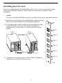
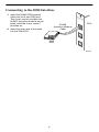
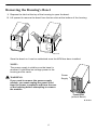
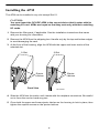
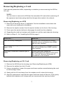
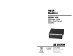
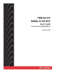
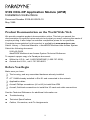
TM
9109 OCU-DP Application Module (APM)
Installation Instructions
Document Number 9109-A2-GN15-10
May 1999
Product Documentation on the World Wide Web
We provide complete product documentation online. This lets you search the
documentation for specific topics and print only what you need, reducing the waste of
surplus printing. It also helps us maintain competitive prices for our products.
Complete documentation for this product is available at www.paradyne.com.
Select Library → Technical Manuals → NextEDGE Multiservices Access System.
Select the following document:
9191-A2-GH30
NextEDGE Multiservices Access System Technical Reference
To request a paper copy of a Paradyne document:
Within the U.S.A., call 1-800-PARADYNE (1-800-727-2396)
Outside the U.S.A., call 1-727-530-8623
Before You Begin
Make sure you have:
The housing, and any associated hardware already installed
A T1 NAM already installed in Slot 01 and connected to the network
Applicable cables
A small Phillips screwdriver (#1 or #2) to install the APM
A small, flat-blade screwdriver to install the I/O card and cable connections
See the Technical Reference for additional information on:
Troubleshooting
Technical Specifications
Cables, Connectors, and Pin Assignments
1
Package Checklist
Verify that your package contains the following:
OCU-DP APM
OCU-DP I/O card
When your equipment arrives, inspect it for physical damage and tighten any screws
that may have worked loose. Contact your sales representative immediately if there are
any signs of shipping damage or if anything is missing from your package. Otherwise,
proceed with the installation.
Equipment You May Need to Order
A DDS Network cable must be ordered for this product (either the 14 ft., Feature No.
3600F3-501, or 25 ft., Feature No. 3600-F3-502).
NOTE:
The following NAM I/O versions are required to use the OCU-DP APM:
— The SINGLE T1 NAM for Model 9161
— The DUAL T1 NAM for Model 9261
! HANDLING PRECAUTIONS FOR STATIC-SENSITIVE DEVICES
This product is designed to protect sensitive components from
damage due to electrostatic discharge (ESD) during normal
operation. When performing installation procedures,
however, take proper static control precautions to
prevent damage to equipment. If you are not sure
of the proper static control precautions, contact
your nearest sales or service representative.
2
496-15149
Installing the I/O Card
The I/O card provides the APM with DDS connections. The I/O card inserts directly
behind the APM that it supports. Slot numbers are identical to facilitate correct
installation.
NOTE:
For the 2-port OCU-DP APM, only Port 1 and Port 2 on the I/O card are functional.
1. Remove the I/O card from the shipping box. Handle only by
the top and bottom edges to avoid damaging the card.
2. At the rear of the housing, align the I/O card with the upper
and lower tracks of the slot. Push gently towards the
midplane until it stops and you cannot push the card any
further.
91
09
OC
U
Port 1
5-Slot
PO
RT
2-Slot
1
Rear View
Port 2
PO
RT
2
Port 3
PO
RT
3
Port 4
PO
RT
4
Port 5
Screws
PO
RT
98-15150-02
5
Port 6
3. There are two captive screws on the I/O card. Alternately
tighten each screw until both are snug.
PO
RT
6
98-15922
3
Connecting to the DDS Interface
1. Insert the RJ48S DDS network
cable into the 4-wire DDS port.
The 2-port version provides two
RJ48S, 8-position modular keyed
jacks, while the 6-port version
provides six.
91
09
OC
U
RJ48S
8-position Modular
Cable
2. Insert the other end of the cable
into the DSU/CSU.
COMSPHERE
OCU
PO
RT
1
PO
3610
RT
2
DDS
DSU
PO
RT
3
98-15970
4
Removing the Housing’s Bezel
1. Depress the latch at the top of the housing to open the bezel.
2. Lift upward to remove the bezel from the two slots at the bottom of the housing.
496-15123
Save the bezel so it can be reattached once the APM has been installed.
NOTE:
The power supply is visible once the bezel is
removed. It provides low voltage power to the
housing and its cards.
Power
Supply
! WARNING:
If you need to remove the power supply
module, you must unplug the power cord
from the power receptacle and from the rear
of the housing before attempting to remove
the module.
Front View
(without Bezel)
98-15174-01
5
Installing the APM
The APM can be installed in any slot except Slot 01.
CAUTION:
You must insert the OCU-DP APM in the correct slot so that it mates with its
matching I/O card. APMs are keyed so that they mate only with their matching
I/O cards.
1. Remove the filler panel, if applicable. See the installation instructions that came
with your housing for information.
2. Remove the APM from the shipping box. Handle only by the top and bottom edges
to avoid damaging the card.
3. At the front of the housing, align the APM with the upper and lower tracks of the
selected slot.
5-Slot
2-Slot
Ejector
Latches
Ejector
Latches
Front View
98-15152-02
4. Slide the APM into the tracks until it seats with the midplane connectors. Be careful
not to force the card or bend any pins.
5. Close both the upper and lower ejector latches on the housing to lock in place, then
tighten the captive screws on the ejector latches.
6
Removing/Replacing a Card
Card removal procedures differ, depending on whether you are removing the APM or
I/O card.
NOTE:
You can insert or remove the APM and its associated I/O card without powering off
the equipment and interrupting data flow through other cards in the network.
Removing/Replacing an APM
1. Remove the housing’s bezel, if applicable. See the installation instructions that
came with your housing for information.
2. Remove the captive screws from the ejector latches on the front of the housing.
3. Press open the ejector latches to disengage the card from the midplane.
4. Supporting the card by its edges, pull straight out until the card clears the housing.
5. Refer to Steps 3 – 5 of Installing the APM on page 6.
If the slot . . .
Then the . . .
Was previously unassigned
Configuration settings are the factory
defaults and are accessible from SNMP
and the user interface.
Was previously assigned to the same
type of APM
Existing configuration settings are used
and are accessible from SNMP and the
user interface.
Previously contained a different type of
APM
System generates a Module
Misconfiguration alarm for the given
slot. See the Technical Reference for
procedures in this situation.
Removing/Replacing an I/O Card
1. Remove the APM from the housing (see Removing/Replacing an APM).
2. Remove the cables from the I/O card.
3. Using a screwdriver, loosen the upper and lower captive screws fastening the card
to the housing’s frame.
4. Gently pull the I/O card away from the midplane until it clears the housing.
5. Align the replacement card with the upper and lower tracks of the slot. Push gently
towards the midplane until it stops and you cannot push the card any further.
7
6. Alternately tighten each captive screw until both are snug.
7. Reattach the cables as appropriate.
Power-On
Refer to the installation instructions that came with your housing to power on the
equipment.
Warranty, Sales, Service, and Training Information
Contact your local sales representative, service representative, or distributor directly for
any help needed. For additional information concerning warranty, sales, service, repair,
installation, documentation, training, distributor locations, or Paradyne worldwide office
locations, use one of the following methods:
H
Internet: Visit the Paradyne World Wide Web site at www.paradyne.com.
(Be sure to register your warranty there. Select Service & Support → Warranty
Registration.)
H
Telephone: Call our automated system to receive current information by fax or to
speak with a company representative.
— Within the U.S.A., call 1-800-870-2221
— Outside the U.S.A., call 1-727-530-2340
Document Feedback
We welcome your comments and suggestions about this document. Please mail them
to Technical Publications, Paradyne Corporation, 8545 126th Ave. N., Largo, FL 33773,
or send e-mail to [email protected]. Include the number and title of this
document in your correspondence. Please include your name and phone number if you
are willing to provide additional clarification.
Trademarks
All products and services mentioned herein are the trademarks, service marks,
registered trademarks or registered service marks of their respective owners.
*9109–A2–GN15–10*
Copyright E 1999 Paradyne Corporation
8