1
Operating Instructions
Color CCTV Camera
Model No.
WV-CW334S, WV-CW334SE
WV-CW364S, WV-CW364SE
Before attempting to connect or operate this product, please read these
instructions carefully and save this manual for future use.
The model number is abbreviated in some descriptions in this manual.
For U.S. and Canada:
WV-CW334S, WV-CW364S
For Europe and other countries:
WV-CW334SE, WV-CW364SE
WARNING:
• This apparatus must be earthed.
• Apparatus shall be connected to a mains socket outlet with a protective earthing connection.
• The mains plug or an appliance coupler shall
remain readily operable.
• All work related to the installation of this product should be made by qualified service personnel or system installers.
• For PERMANENTLY CONNECTED
APPARATUS provided neither with an all-pole
MAINS SWITCH nor an all-all pole circuit
breaker, the installation shall be carried out in
accordance with all applicable installation
rules.
• The connections should comply with local
electrical code.
UL listed model No.:
WV-CW334S, WV-CW364S
For Canada
This Class A digital apparatus complies with
Canadian ICES-003.
For U.S.A.
NOTE: This equipment has been tested and
found to comply with the limits for a Class A digital device, pursuant to Part 15 of the FCC Rules.
These limits are designed to provide reasonable
protection against harmful interference when the
equipment is operated in a commercial environment. This equipment generates, uses, and can
radiate radio frequency energy and, if not installed
and used in accordance with the instruction manual, may cause harmful interference to radio communications.
Operation of this equipment in a residential area
is likely to cause harmful interference in which
case the user will be required to correct the interference at his own expense.
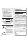
CAUTION
RISK OF ELECTRIC
SHOCK DO NOT OPEN
CAUTION: TO REDUCE THE RISK OF ELECTRIC SHOCK,
DO NOT REMOVE COVER (OR BACK).
NO USER-SERVICEABLE PARTS INSIDE.
REFER SERVICING TO QUALIFIED SERVICE PERSONNEL.
FCC Caution: To assure continued compliance,
(example - use only shielded interface cables
when connecting to computer or peripheral
devices). Any changes or modifications not
expressly approved by the party responsible for
compliance could void the user’s authority to
operate this equipment.
The lightning flash with arrowhead symbol, within an equilateral triangle, is intended to alert
the user to the presence of
uninsulated "dangerous voltage" within the product's enclosure that may be of sufficient
magnitude to constitute a risk of
electric shock to persons.
The exclamation point within an
equilateral triangle is intended
to alert the user to the presence
of important operating and
maintenance (servicing) instructions in the literature accompanying the appliance.
2
For U.S.A.
The model number and serial number of this
product may be found on the surface of the
unit.
You should note the model number and serial
number of this unit in the space provided and
retain this book as a permanent record of your
purchase to aid identification in the event of
theft.
Model No.
Serial No.
We declare under our sole responsibility that the product
to which this declaration relates is in conformity with the
standards or other normative documents following the
provisions of Directives 2006/95/EC and 2004/108/EC.
Wir erklären in alleiniger Verantwortung, daß das Produkt,
auf das sich diese Erklärung bezieht, mit den folgenden
Normen oder normativen Dokumenten übereinstimmt.
Gemäß den Bestimmungen der Richtlinie 2006/95/EC
und 2004/108/EC.
CAUTION:
An ALL-POLE MAINS SWITCH with a contact
separation of at least 3 mm in each pole shall be
incorporated in the electrical installation of the
building.
Turn the power off at the mains to disconnect the
main power for all unit.
FOR YOUR SAFETY PLEASE READ THE
FOLLOWING TEXT CAREFULLY.
WARNING: This apparatus must be earthed.
IMPORTANT
The wires in this mains lead are coloured in accordance with the following code.
Green-and-yellow:
Earth
Blue:
Neutral
Brown:
Live
As the colours of the wire in the mains lead of
this appliance may not correspond with the
coloured markings identifying the terminals in your
plug, proceed as follows.
The wire which is coloured green-and-yellow
must be connected to the terminal in the plug which
is marked with the letter E or by the earth symbol I
or coloured green or green-and-yellow.
The wire which is coloured blue must be connected to the terminal in the plug which is marked
with the letter N or coloured black.
The wire which is coloured brown must be connected to the terminal in the plug which is marked
with the letter L or coloured red.
Nous déclarons sous notre propre responsabilité que le
produit auquel se réfère la présente déclaration est
conforme aux normes spécifiées ou à tout autre
document normatif conformément aux dispositions des
directives 2006/95/CE et 2004/108/CE.
Nosotros declaramos bajo nuestra única responsabilidad
que el producto a que hace referencia esta declaración
está conforme con las normas u otros documentos
normativos siguiendo las estipulaciones de las directivas
2006/95/CE y 2004/108/CE.
Noi dichiariamo sotto nostra esclusiva responsabilità che
il prodotto a cui si riferisce la presente dichiarazione
risulta conforme ai seguenti standard o altri documenti
normativi conformi alle disposizioni delle direttive
2006/95/CE e 2004/108/CE.
Wij verklaren als enige aansprakelijke, dat het product
waarop deze verklaring betrekking heeft, voldoet aan de
volgende normen of andere normatieve documenten,
overeenkomstig de bepalingen van Richtlijnen 2006/95/
EC en 2004/108/EC.
Vi erklærer os eneansvarlige for, at dette produkt, som
denne deklaration omhandler, er i overensstemmelse
med standarder eller andre normative dokumenter i følge
bestemmelserne i direktivene 2006/95/EC og 2004/108/
EC.
Vi deklarerar härmed vårt fulla ansvar för att den produkt
till
vilken
denna
deklaration
hänvisar
är
i
överensstämmelse med de standarder eller andra
normativa dokument som framställs i direktiv nr 2006/95/
EC och 2004/108/EC.
Ilmoitamme yksinomaisella vastuullamme, että tuote, jota
tämä ilmoitus koskee, noudattaa seuraavia standardeja
tai muita ohjeellisia asiakirjoja, jotka noudattavat
direktiivien 2006/95/EC ja 2004/108/EC säädöksiä.
Vi erklærer oss alene ansvarlige for at produktet som
denne erklæringen gjelder for, er i overensstemmelse
med følgende normer eller andre normgivende
dokumenter som følger bestemmelsene i direktivene
2006/95/EC og 2004/108/EC.
3
Important safety instructions
1) Read these instructions.
2) Keep these instructions.
3) Heed all warnings.
4) Follow all instructions.
5) Clean only with dry cloth.
6) Do not block any ventilation openings. Install in accordance with the manufacturer's instructions.
7) Do not install near any heat sources such as radiators, heat registers, stoves, or other apparatus (including amplifiers) that produce heat.
8) Do not defeat the safety purpose of the polarized or grounding-type plug. A polarized plug has
two blades with one wider than the other. A grounding type plug has two blades and a third
grounding prong. The wide blade or the third prong are provided for your safety. If the provided
plug does not fit into your outlet, consult an electrician for replacement of the obsolete outlet.
9) Protect the power cord from being walked on or pinched particularly at plugs, convenience
receptacles, and the point where they exit from the apparatus.
10) Only use attachments/accessories specified by the manufacturer.
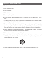
11) Use only with the cart, stand, tripod, bracket, or table specified by the manufacturer, or sold
with the apparatus. When a cart is used, use caution when moving the cart/apparatus combination to avoid injury from tip-over.
S3125A
12) Unplug this apparatus during lightning storms or when unused for long periods of time.
4
Limitation of liability
THIS PUBLICATION IS PROVIDED "AS IS" WITHOUT WARRANTY OF ANY KIND, EITHER
EXPRESS OR IMPLIED, INCLUDING BUT NOT LIMITED TO, THE IMPLIED WARRANTIES OF
MERCHANTABILITY, FITNESS FOR ANY PARTICULAR PURPOSE, OR NON-INFRINGEMENT OF
THE THIRD PARTY'S RIGHT.
THIS PUBLICATION COULD INCLUDE TECHNICAL INACCURACIES OR TYPOGRAPHICAL
ERRORS. CHANGES ARE ADDED TO THE INFORMATION HEREIN, AT ANY TIME, FOR THE
IMPROVEMENTS OF THIS PUBLICATION AND/OR THE CORRESPONDING PRODUCT (S).
Disclaimer of warranty
IN NO EVENT SHALL Panasonic System Networks Co., Ltd. BE LIABLE TO ANY PARTY OR ANY
PERSON, EXCEPT FOR REPLACEMENT OR REASONABLE MAINTENANCE OF THE PRODUCT,
FOR THE CASES, INCLUDING BUT NOT LIMITED TO BELOW:
(1) ANY DAMAGE AND LOSS, INCLUDING WITHOUT LIMITATION, DIRECT OR INDIRECT, SPECIAL, CONSEQUENTIAL OR EXEMPLARY, ARISING OUT OF OR RELATING TO THE PRODUCT;
(2) PERSONAL INJURY OR ANY DAMAGE CAUSED BY INAPPROPRIATE USE OR NEGLIGENT
OPERATION OF THE USER;
(3) UNAUTHORIZED DISASSEMBLE, REPAIR OR MODIFICATION OF THE PRODUCT BY THE
USER;
(4) INCONVENIENCE OR ANY LOSS ARISING WHEN IMAGES ARE NOT DISPLAYED, DUE TO
ANY REASON OR CAUSE INCLUDING ANY FAILURE OR PROBLEM OF THE PRODUCT;
(5) ANY PROBLEM, CONSEQUENTIAL INCONVENIENCE, OR LOSS OR DAMAGE, ARISING
OUT OF THE SYSTEM COMBINED BY THE DEVICES OF THIRD PARTY;
(6) ANY CLAIM OR ACTION FOR DAMAGES, BROUGHT BY ANY PERSON OR ORGANIZATION
BEING A PHOTOGENIC SUBJECT, DUE TO VIOLATION OF PRIVACY WITH THE RESULT OF
THAT SURVEILLANCE-CAMERA'S PICTURE, INCLUDING SAVED DATA, FOR SOME REASON, BECOMES PUBLIC OR IS USED FOR ANY PURPOSE;
(7) LOSS OF REGISTERED DATA CAUSED BY ANY FAILURE.
5
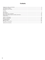
Contents
Important safety instructions.......................................................................................................... 4
Limitation of liability........................................................................................................................ 5
Disclaimer of warranty.................................................................................................................... 5
Preface........................................................................................................................................... 7
Features.......................................................................................................................................... 7
Precautions.................................................................................................................................... 8
Precautions for installation........................................................................................................... 10
Major operating controls and their functions............................................................................... 12
Preparations................................................................................................................................. 15
Camera installation....................................................................................................................... 19
Make a connection....................................................................................................................... 28
Troubleshooting............................................................................................................................ 31
Specifications............................................................................................................................... 32
Standard accessories................................................................................................................... 34
Optional accessories.................................................................................................................... 35
6
Preface
This product is surveillance color CCTV camera equipped with a 1/3 type CCD solid-state image
sensor with 768 horizontal pixels (NTSC), 752 horizontal pixels (PAL).
This camera can be mounted on a ceiling or a wall without any difficulty.
Features
This product is provided with the adaptive black stretch function, high resolution of 540 TV lines
(horizontal), and minimum illuminance of 0.6 lx (C/L), 0.05 lx (B/W) for WV-CW364S, 0.4 lx (B/W) for
WV-CW334S, (F1.3(WIDE)) thanks to the adoption of the newly developed digital signal processor.
Optional heater unit can be connected
When using the optional heater unit, the product can be used at temperatures within –30 °C to
+50 °C {–22 °F to + 122 °F} and humidity below 90 %.
7
Precautions
The following points as well as the contents of "Warning" and "Caution" shall be
observed.
Refer installation work to the dealer.
Installation work requires technique and experiences. Otherwise injury, or damage to this
product may result.
Be sure to consult the dealer.
Install this product high enough to ensure
that people don't hit their heads.
Failure to observe this may cause a drop resulting in injury or accidents.
Do not insert any foreign objects.
This could permanetly damage this product.
Turn the power off immediately and contact
qualified service personnel for service.
Do not strike or give a strong shock to this
product.
Failure to observe this may cause injury or fire.
Do not attempt to disassemble or modify
this product.
Failure to observe this may cause fire or electric
shock.
Consult the dealer for the repair or inspections.
Turn the power off when do wiring of this
product.
Failure to observe this may cause electric
shock. A short circuit or wrong wiring may
cause fire.
Stop operation immediately when something is wrong with this product.
When smoke goes up from this product or the
smell of smoke comes from this product, continued use will result in fire, injury, or damage to
the product.
Turn the power off immediately and contact
qualified service personnel for service.
Do not use this product in an atmosphere
of flammable gases.
Failure to observe this may cause injury by
explosion.
Select an installation area that can support the total weight.
Selecting an inappropriate installation surface
may cause the product to fall down or topple
over, resulting in injury.
Installation work shall be started after sufficient
reinforcement.
Periodic inspections shall be conducted.
Rust on the metal parts or screws may cause
the product to fall down resulting in injury or
accidents.
Consult the dealer for the inspections.
8
This product shall be installed in a vibration-free place.
Failure to observe this may cause screws and
bolts to be loosened and consequently to fall
resulting in injury.
Avoid installing this product in locations
where it is subject to damage by salt or
corrosive gas.
Otherwise the mounting fixtures will deteriorate,
causing the product to fall down and leading to
accidents.
Use the specified mount bracket.
Failure to observe this may cause a drop resulting in injury or accidents.
Do not rub the edges of metal parts with
your hand.
Failure to observe this may cause injury.
Tighten screws and mounting fixtures to
the specified torque.
Failure to observe this may cause a drop resulting in injury or accidents.
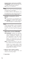
[Precautions for use]
This product has no power switch.
When turning off the power, turn off a circuit
breaker.
Cleaning this product body
Turn the power off when cleaning this product.
Do not use strong abrasive detergent when
cleaning this product. Otherwise, it may cause
discoloration.
To keep on using with stable performance
Parts of this product may deteriorate and it
may shorten the lifetime of this product when
using in locations subject to high temperatures
and high humidity. (Recommended operating
temperature: +35 °C {95 °F} or lower)
Do not expose this product to direct heat
sources such as a heater.
Handle this camera with care.
Do not drop this camera, nor apply shock or
vibration to this camera.
Failure to observe this may cause trouble.
Do not touch the dome cover with your
bare hands.
A dirty dome cover causes deterioration of picture quality.
Discoloration on the CCD color filter
When continuously shooting a bright light
source such as a spotlight, the color filter of the
CCD may have deteriorated and it may cause
discoloration. Even when changing the fixed
shooting direction after continuously shooting a
spotlight for a certain period, the discoloration
may remain.
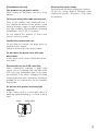
Do not aim this product at strong light
sources.
A light source such as a spot light causes a
blooming (light bleeding) or a smear (vertical
lines).
Smear
Blight subject
Blooming
9
Precautions for installation
The following points as well as the contents of "Warning" and "Caution" shall be
observed.
Panasonic assumes no responsibility for
injuries or property damage resulting from
failures arising out of improper installation
or operation inconsistent with this documentation.
Installation work shall be performed in
accordance with the technology standard
of the electric installation.
This product is designed to be installed
under eaves.
Keep the product out of direct sunlight.
Installing place
Contact your dealer for assistance if you are
unsure of an appropriate place in your particular environment.
• Make sure that the installation area is
strong enough to hold the product, such
as a concrete ceiling.
• Install the camera in the foundation area of
the architecture or where sufficient strength
is assured.
• If a ceiling board such as plaster board is
too weak to support the total weight, the
area shall be sufficiently reinforced.
Avoid installing this product in the following locations.
• Locations where a chemical agent is used
such as a swimming pool.
• Locations subject to steam and oil smoke
such as a kitchen, Locations near flammable gas or vapor.
• Locations where radiation or x-ray emissions are produced.
• Locations where corrosive gas is produced, Locations where it may be damaged by briny air such as seashores.
10
• Locations where the temperature is not
within –10 °C to +50 °C {14 °F to +122 °F}.
(When using the optional heater unit, the
product can be used at temperatures within –30 °C to +50 °C {–22 °F to +122 °F}
and humidity below 90 %.)
• Locations subject to vibrations (This product is not designed for on-vehicle use.)
Avoid moist or dusty places to install this
system.
Otherwise, lifetime of the internal parts may be
shortened.
Avoid installing the camera in a place with
a high level of noise.
Installation near an air conditioner, an air cleaner, a vending machine, or the like causes noise.
Be sure to remove this product if it is not
in use.
Keep the camera cable away from the
lighting cable.
Failure to observe this may cause noise.
Radio interference
When this product is used near TV/radio antenna, strong electric field or magnetic field (near a
motor or a transformer), images may be distorted and noise sound may be produced.
In such a case, run the camera cable through
specialized steel conduit tubes.
Locally procure the screws
Screws are not supplied with this product. Prepare the screws according to the material,
structure, strength and other factors of the
mounting area and the total weight of objects
to be mounted.
Screw tightening
• The screws and bolts must be tightened
with an appropriate tightening torque
according to the material and strength of
the installation area.
• Do not use an impact driver. Failure to
observe this may cause overtightening and
consequently damage to the screws.
• When a screw is tightened, make the
screw at a right angle to the surface. After
tightening the screws or bolts, perform
visual check to ensure tightening is enough
and there is no backlash.
Do not remove or loosen the screws.
Do not remove or even loosen the screws (7
pieces) on the rear of the camera.
Otherwise, water exposure may cause damage
or malfunction of camera, or camera dropping
may result in injury.
11
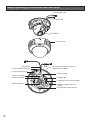
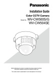
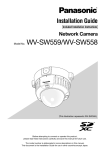
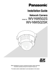
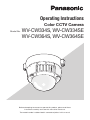
Major operating controls and their functions
w Video output cable
q Power cord
!5 Inner dome
e Dome cover
!3 Dip switch
!2 Heater output connector
1
2
3
4
!1 Camera fixing screw
* This illustration shows the camera
without the inner dome.
t Panning table
!0 Focus lock knob
o Zoom lock knob
y Tilting table
u Tilting lock screw (left and right)
i Azimuth adjuster
12
!4 Monitor output connector
(RCA)
r Panning lock screw [LOCK]
q Power cord
Supplies 24 V AC or 12 V DC from an
external power source.
w Video output cable
Transmits composite video signals. If this
unit is connected to the multiplex unit, the
multiplexed VD2 that is prioritized over INT
is automatically selected.
e Dome cover
r Panning lock screw [LOCK]
Fixes the panning table.
t Panning table
Rotate this table to adjust the panning
angle of the camera.
y Tilting table
Adjusts the tilting position of the camera.
u Tilting lock screws (left and right)
Fixes the tilting position.
i Azimuth adjuster
Adjusts the azimuth angle of the camera.
o Zoom lock knob
Fixes the zoom position after adjusting.
!0 Focus lock knob
Fixes the focus position after adjusting.
!1 Camera fixing screw
Fixes the attachment on the camera body.
!2 Heater output connector
Connects to the optional heater unit.
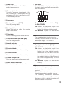
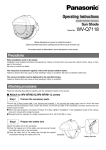
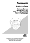
!3 Dip switch
Turns ON/OFF the day/night mode, adaptive black stretch, backlight compensation,
and white balance.
B.S.
D/N
BLC
ATW
ON
OFF
AWC
Simple day/night mode selector [D/N]
for WV-CW334S:
ON: Selects the black-white mode if the
picture is dark; it selects the color
mode if the picture is bright enough.
OFF (default): Displays the color picture
normally.
Note:
• The simple day/night function is established by using the SENSE UP function for
black-white images. The IR filter is
secured.
Day/night mode selector [D/N] for
WV-CW364S:
ON: Selects the black-white mode if the
picture is dark; it selects the color
mode if the picture is bright enough.
When set to ON, the camera switches
from color to black-white images when
the ambient brightness (illuminance) of
the camera is approximately 0.6 lx or
less.
OFF (default): Displays the color picture
normally.
Note:
• To obtain color images, a sufficient level of
illuminance (approximately 30 lx or more) is
required.
• The switching illuminance level varies
depending on subjects and light sources.
• The switching illuminances described
above are reference values. The switching
illuminance shall be decided based on the
actual installation environment.
13
Adaptive black stretch selector [B.S.]:
ON (default): Corrects the dark area of an
object automatically to lighten it.
OFF: Does not compensate.
Note:
• When set to "ON", noise may be increased
in the dark area of the object.
In addition, darkness and brightness may
be emphasized in the vicinity of the boundary between the dark and bright areas.
Backlight compensation selector
[BLC]:
ON: Compensates the background automatically if it is brighter than the object.
OFF (default): Uses this mode when the
front of the object is extremely bright.
Note:
• Under some conditions, such as extremely
strong backlight, the desired compensation effect may not be achieved even if the
mode is set to ON to detect the backlight
level.
White balance selector [ATW/AWC]:
ATW (default): Activates the automatic
color temperature tracking mode. The
camera continuously measures the
color temperature of the light source
and automatically adjusts the white
balance. The adjustment of the color
temperature ranges from approximately 2700 K to 6000 K.
AWC: Activates the automatic white balance control mode. This adjustment is
suitable for a location where a light
source is stable. The adjustment of the
color temperature ranges from approximately 2000 K to 10000 K.
!4 Monitor output connector (RCA)
Connects the LCD monitor and such
devices for checking images.
!5 Inner dome
14
Preparations
When installing the camera on a wall or a ceiling, there are two methods as specified below.
(+ Next page)
• Using a two-gang junction box
• Using the mounting base
Refer to all work related to the installation of this product to qualified service personnel or system
installer.
• The mounting base is supplied. Use the screws supplied with this product.
Important:
• Prepare the mounting screw according to the material of the area where the camera attachment (accessory) is to be installed. In this case, wood screws and nails should not be used. For
mounting a camera on a concrete ceiling, use an anchor bolt (M4) or an AY plug bolt (M4) for
securing.
(Recommended tightening torque M4: 1.6 N·m {1.18 lbf·ft})
• When using the provided camera attachment, make sure that either of the arrow marks faces
upward.
• Required pull-out capacity of a single screw/bolt is 196 N {44.06 lbf} or more.
• If a ceiling board such as plaster board is too weak to support the total weight, the area shall
be sufficiently reinforced.
• When using an optional mounting bracket, refer to the operating instructions of the bracket in
use.
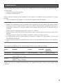
The mounting conditions of the camera mount bracket are described as follows:
Installation
place
Applicable mount
bracket
Recommended
screw
Number
of screw
Minimum pull-out
strength
(per 1 pc.)
Ceiling/wall
Two-gang junction box
M4 or equivalent
4 pcs.
196 N {44.06 lbf}
Ceiling/wall
Mounting base
(approx. 350 g {0.77 lbs})
M4 or equivalent
4 pcs.
196 N {44.06 lbf}
Ceiling
WV-Q169
(approx. 700 g {1.55 lbs})
–
–
*
* Make sure that the installed mount bracket can support more than 5 times of the weight of the
camera.
15
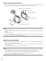
Using a two-gang junction box
• When the camera is installed using the two-gang junction box, mount the camera attachment
(accessory) to the embedded box installed on the wall or ceiling as a first step.
[Mounting position on wall or ceiling]
46 mm {1-13/16 inches}
Two-gang junction box
FRO
NT
TOP
FRON
T
TOP
83.5 mm {3-9/32 inches}
Camera attachment (accessory)
Note:
• For wall mounting:
Installation shall be performed in such a manner that "MTOP" of the camera attachment faces
upward.
• For ceiling mounting:
The front side (model number indication face) of the camera shall be aligned in the direction of
the arrow in "<FRONT" on the camera attachment.
Using the mounting base
• When installing the camera with the mounting base, attach the mounting base to the wall or
ceiling in the first place. (+ next page.)
Mount the camera attachment (accessory) by using the screws supplied with mounting bracket. (+ next page.)
(Recommended tightening torque: 0.78 N·m {0.58 lbf·ft})
Note:
• When installing the camera on the wall or ceiling where cable holes are already provided, or
when installing the camera with exposed wiring, the mount bracket shall be used.
• The female screws for piping conform to ANSI NPSM (parallel pipe threads) 3/4 inches.
The female screws for piping shall be removed with a hexagon wrench.
• To connect conduit from the top, refer to page 27.
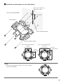
16
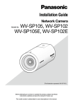
z Install the mounting base on the wall/ceiling.
ø27 mm {1-1/16 inches}
Cable access hole
(A For use of the hole)
51 mm {2 inches}
Mounting base
A
B
A
Center of mounting base
B
B
A
Female thread for conduit
(For use of the hole A)
(For use of the hole B)
85 mm
{3-11/32 inches}
138 mm
{5-7/16 inches}
138 mm
{5-7/16 inshes}
85 mm
{3-11/32 inches}
Note:
• Only the same type of holes, A or B, shall be
used for mounting.
B
A
A
B
B
A
A
B
17
xPreviously run the cables from the wall or ceiling through the cable access hole.
cMount the attachment onto the mount bracket.
Recommended tightening torque: 0.78 N·m {0.58 lbf·ft}
FRO
NT
TOP
Camera attachment
Note:
• For wall mounting:
Installation shall be performed in such a manner that "MTOP" of the camera attachment faces
upward. (Except for the case of connecting the conduit from the top. (+ page 27))
• For ceiling mounting:
The front side (model number indication face) of the camera shall be aligned in the direction of
the arrow in "<FRONT" on the camera attachment.
• Ensure that any one of the arrows on the mount bracket is aligned with the arrow of "MTOP" on
the attachment.
18
Camera installation
z Mount the camera.
LOCK
OPEN
<To mount the camera on a two-gang junction box>
q Connect the power cord and the video output cable. (+ page 28)
w Align the "OPEN" mark of the camera with the protrusion of the camera attachment.
e Engage the attachment mounting screw of the camera with the camera mounting hole of the
camera attachment and rotate the camera in the direction of the arrow to the "LOCK" position
to secure the camera to the camera attachment without any backlash.
Camera mounting hole
Protrusion
FRO
NT
TOP
Attachment mounting screw
19
LO
C
K
OP
EN
<To use the mounting base>
q Attach the camera onto the camera attachment
while aligning the "OPEN" mark of the camera
with the projection of the camera attachment.
LO
CK
OP
EN
Projection
Important:
• When mounting the camera body, cables shall
be run between the camera attachment and
mounting base as indicated by the arrow in the
illustration.
* Cable running as indicated by the arrow is an
example. Cable running shall be varied with
installation environment.
20
LO
CK
OP
EN
w Engage the attachment mounting screw of
the camera with the camera mounting hole
of the camera attachment and rotate the
camera in the direction of the arrow to the
"LOCK" position to secure the camera to
the camera attachment without any backlash.
LO
CK
OP
EN
Projections
e Connect the power cord and the video
output cable at the side of the mounting
base. (+ page 28)
Apply waterproof treatment to the connected section. (+ page 26)
Make cable
connections.
r Accommodate the connected cables
inside the cable guide of the mounting
base.
Important:
• To prevent the cables from being caught
when the cover is attached, keep the
cables inside the cable guide.
Cable guide
Connected cable
Cable guide
21
t Mount the supplied base cover on the
mounting base.
Important:
• To prevent the cables from being caught
when the base cover is attached, keep the
cables inside the cable guide.
Base cover
y Use the bit for tamperproof screw (accessory) to tighten the fixing screws provided
on both sides of the base cover.
(Recommended tightening torque:
0.78 N·m {0.58 lbf·ft})
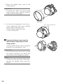
xRemove the dome cover from the
main body by loosening the three
fixing screws.
Loosen the three fixing screws by using the
provided bit for tamperproof screw.
Important:
• Do not hold the inner dome when carrying
the camera. Otherwise, the camera part
may fall and it may damage the camera.
Note:
• Perform the same procedure when replacing with the optional dome cover WVCW4S.
22
Base cover fixing screw
cSecure the camera to the bracket
with the camera fixing screw (red, 1
position).
Important:
• The camera fixing screw shall be securely
tightened. Otherwise, water exposure may
cause damage or malfunction of camera,
or camera dropping may result in injury.
(Recommended tightening torque:
0.78 N·m {0.58 lbf·ft})
23
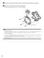
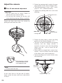
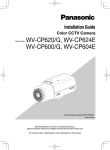
Adjust the camera
zPan, tilt and azimuth adjustment
Important:
• Do not touch the iris motor. Failure to
observe this may cause trouble.
• Do not hold the camera by the lens unit
when adjusting panning, tilting, or azimuth.
q Rotate the panning table to adjust the panning position of the camera. (Range: 320°)
• The adjusting range is from +180 ° (clockwise) to –140 ° (counterclockwise).
• Tighten the panning table lock screw after
adjusting
Panning lock screw
Detach the inner dome from the camera by
picking the front and rear sides.
CCW: –140 °
Panning table
Indication
: CCD up side
CW: +180 °
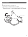
w Rotate the tilting table to adjust the tilting
position of the camera (Range: ±75 °).
• This lens can also be rotated in the reverse
direction, but the image azimuth is
reversed. In such a case, turn the panning
table to the 180 ° side to correct the azimuth image.
• When used at an angle that is close to horizontal, it must be noted that the shadow
of the dome cover may be projected.
• Fasten the tilting lock screws of both sides
after adjusting.
Pick the portion marked
in the illustration as well
as the opposite side.
Note:
• Do not touch the lens.
Tilting lock
Pick the portion marked
screw (x2)
in the illustration as well
as the opposite side.
At the same time as the pan and tilt adjustments, make the zoom and focus adjustments
in Step 2.
24
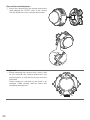
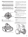
Variable tilt angle: ±75 °
Note:
• When the zoom lock knob is adjusted to
the WIDE side and the tilt angle is approx.
±75 °, 1/3 part of the screen may be hidden.
Important
• Tighten the panning table lock screw and
tilting lock screw. (Recommended tightening torque: 0.59 N·m {0.44 lbf·ft})
e Rotate the azimuth adjuster to adjust the
azimuth angle of the image (Range:
±100°).
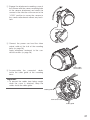
q Loosen the zoom lock knob and move the
knob between TELE and WIDE to obtain
the appropriate angle of view. Tighten the
zoom lock knob.
w Loosen the focus lock knob and move the
knob between FAR and NEAR to obtain
the optimum focus. Tighten the focus lock
knob.
Note:
• To change the angle of view by moving the
zoom lock knob, also move the focus lock
knob to adjust the focus.
cMount the dome cover and inner
Azimuth adjuster
Rotating angle:
–100 °
Rotating angle:
+100 °
Indication
xZoom and focus adjustment
At the same time as adjusting the pan and
tilt(Step 2), adjust the zoom and focus.
NEAR
FAR
TELE
dome.
Tighten the screws that have been loosened in Step 2 in page 22 using the supplied driver bit.
(Recommended tightening torque:
0.78 N·m {0.58 lbf·ft})
Important:
• Attach the inner dome in accordance with
the lens direction to not to change the lens
direction.
• Check if the tabs of the inner dome are
firmly fit.
• Remove the protection sheet from the outside of the dome.
Cutout for
mounting
Groove for
mounting
WIDE
This illustration represents WV-CW364S.
25
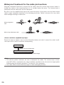
Waterproof treatment for the cable joint sections
Adequate waterproof treatment is required for the cables when the camera with exposed cables is
installed by means of the mounting base or it is installed under the eaves. The camera body is
waterproof, but the cable ends are not waterproof.
Be sure to use the supplied butyl tape at the connection parts of the power cord and video output
cable to apply waterproof treatment in the following procedure. Failure to observe this may cause
water leakage resulting in malfunction.
When using power
cord
When using video output cable
<How to wind the supplied butyl tape>
Stretch the tape by approx. twice (see the illustration below) and wind it around the cable. Insufficient tape stretch causes insufficient waterproofing.
Stretch the tape to about twice.
Dobled length
Note:
• To install this product outdoors, be sure to waterproof the cables. The camera body is waterproof (IEC IP66 or equivalent) only when installation specified in this document and appropriate
waterproofing are properly performed. The bracket is not waterproof.
• The cable shall be wound with butyl tape in a half-overlapping manner.
26
Important:
• If open wiring is conducted, be sure to use conduits and run the cables inside the tubes to protect the cables from direct sunlight.
• When the conduit is connected at the lateral or bottom position, either of the arrow marks on
the bracket shall be the top position.
• When the conduit is connected from the top, the arrow mark on the attachment shall be either
of the right or left position.
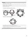
<To connect conduit from the side or bottom>
Arrow mark
Connecting
conduit
<To connect conduit from the top>
FRONT
TOP
• For installation on the wall, do not connect the dehumidifying device at the upper side to prevent water from being stored in the dehumidifying device.
If water remains inside, the dehumidifying device cannot function properly.
• Installation work shall be such that there is no intrusion of water into the architecture through
the conduits having been joined.
27
Make a connection
Cautions:
• FOR UL LISTED MODEL(S), ONLY CONNECT THIS TO 24 V AC OR 12 V DC CLASS 2
POWER SUPPLY.
• Be sure to connect the grounding lead to the GND terminal.
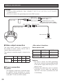
Power cord
BNC connector
Brown (Live)
Blue (Neutral)
To 24 V AC/12 V DC*
power supply
Green/Yellow (GND)
To GND (only for 24 V AC)
* When using 12 V DC power supply,
the optional heater unit is unavailable.
BNC connector
Video output cable
BNC connector
To VIDEO IN
l Video output connection
• Wire colors & functions
The video output connector is connected to
the monitor or other system devices with a
coaxial cable (locally procured).
The maximum extensible length is shown in the
table.
Camera power cord
Type of coaxial
RG-59/U RG-6/U RG-11/U RG-15/U
cable
(3C-2V) (5C-2V) (7C-2V) (10C-2V)
Recommended m
250
500
600
800
maximum
feet
825
1 650
1 980
2 640
cable length
l Power connection
Precaution:
The following connections should be made
by qualified service personnel or system
installers in accordance with local electrical
code (NEC 725-51 for NTSC model).
28
Wire color
24 V AC
12 V DC
Brown
24 V AC (L)
Positive
Blue
24 V AC (N)
Negative
Green/yellow
To GND
–
Cautions:
• Be sure to connect the GND (grounding)
lead of the camera and grounding terminal
of the power supply when using a 24 V AC
power source.
• Shrinking the cable-entry seal is a onetime
procedure. Do not shrink the cable-entry
seal until it has been ascertained that unit
is functioning.
• Cord length and wire gauge
24 V AC
The recommended cord length and copper
wire size are shown in the table for reference.
The voltage supplied to the camera should be
between 19.5 V AC and 28 V AC.
Recommended wire gauge for 24 V AC line.
#22
#20
#18
Copper wire size
#24
(AWG)
(0.22 mm2) (0.33 mm2) (0.52 mm2) (0.83 mm2)
Length of
m
20
30
45
75
cable
(approx.)
feet
66
100
150
250
12 V DC
The recommended resisance and copper wire
size are shown in the table for reference.
The voltage supplied to the camera should be
between 10.8 V DC and 16 V DC.
Resistance of copper wire [20 °C {68 °F}]
Copper wire size
(AWG)
#22
#20
#18
#24
(0.22 mm2) (0.33 mm2) (0.52 mm2) (0.83 mm2)
Resistance (Ω/m)
0.078
0.050
0.03
0.018
Resistance (Ω/ft)
0.024
0.015
0.009
0.005
Use the formula below to calculate the power
cord and power supply.
"L", "R", "VA", "I" shall satisfy the inequalitty
below.
10.8 V DC ≤ VA - 2(R x I x L) ≤ 16 V DC
L: Cord length (m) {feet}
R: Resistance of copper wire (Ω/m) {Ω/ft}
VA:DC output voltage of power supply unit
I:DC current consumption (A). See specifications.
Important:
• When using 12 V DC power supply, the
heater is unavailable.
29
Optional Heater Unit WV-CW5H (option)
Installing the heater unit enables the camera to operate in a low-temperature environment below
–30 °C {–22 °F}. The heater turns on automatically when the temperature inside the camera drops
below +10 °C {50 °F} and turns off when the temperature rises. A small fan inside the unit will minimize condensation on the surface of the dome cover caused by changes in ambient temperature
unless temperatures change too rapidly.
Important:
• When using 12 V DC power supply, the optional heater unit is unavailable.
• Turning the heater on and off may disturb the camera images.
• The power supply of the camera shall be turned off when mounting or dismounting the heater.
When servicing, pay attention to high temperature on the surface of the heater unit. Disconnect
the harness and wait until the heater unit cools.
• When the camera is installed and operated in low temperatures below –10 °C {14 °F}, normal
images may not be obtained immediately after startup. In such a case, wait around 60 minutes
or more.
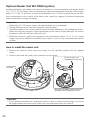
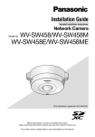
How to install the heater unit
q Remove the camera’s dome cover and mount it in the specified position with the supplied
screw.
w Connect the heater unit cable to the connector of the camera.
Screw for heater unit*
(supplied with heater unit)
Heater output
connector
* Two screws including a spare screw are
provided as the standard accessories.
Important:
• After mounting the heater unit, arrange the harness cable as shown in the drawing so as not to
be tangled around the dome cover, safety wire, and equipment inside the camera.
30
Troubleshooting
Before asking for repairs, check the symptoms with the following table.
Contact your dealer if a problem cannot be solved even after checking and trying the solution in the
table or a problem is not described below.
Symptom
No image displayed
Blurred image
Cause/solution
• Are the power cord and coaxial cable
connected appropriately?
→ Check whether the connection is
appropriately established.
• Is the adjusting monitor connected ?
→ Check whether connection is established.
• Is the monitor brightness appropriately
adjusted, or is the contrast appropriately
adjusted?
→ Check whether the monitor settings
are appropriate.
• Is the dome cover free from contamination and/or flaws?
→ Check the dome cover.
• Is the focus adjusted correctly?
→ Check if the focus is adjusted correctly.
• Is the lens of the camera soiled with dirt
or dust?
→ Check whether the lens of the camera
is clean.
Reference
pages
28
24
–
–
25
–
Damaged power cord
sheathing
Heated portion of power line
consisting of power cord
during use
Warmed power cord or loosened connection by bending
or stretching during use
The power cord and connector is damaged. Use of the damaged cord or connector may cause electric shock or fire.
Turn off the power immediately and request
repair to your dealer.
–
31
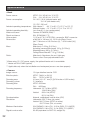
Specifications
• Basic
Power source:
Power consumption:
NTSC:24 V AC 60 Hz, 12 V DC
PAL: 24 V AC 50 Hz, 12 V DC
24 V AC: 2
.9 W (without heater unit)
13.1 W (with heater unit)
12 V DC: 250 mA*
Ambient operating temperature: With Heater**: –30 °C to 50 °C (–22 °F to 122 °F)
Without Heater: –10 °C to 50 °C (14 °F to 122 °F)
Ambient operating humidity:
Less than 90 % (no condensation)
Water resistance:Camera: IEC60529 (IP66)***
Shock resistance: 50J, IEC60068-2-75
Video output:
1.0 V [p-p]/75 Ω, NTSC/PAL composite, BNC connector
Dimensions:ø164 mm x 146 mm (H), 191.5 mm (Base Cover)
{ø6-7/16 inches x 5-3/4 inches (H), 7-9/16 inches (W)}
(Base Cover)
Mass:
Main body: 1.05 kg {2.31 lbs}
(including camera attachment 100 g {0.22 lbs})
Mounting base: 350 g {0.78 lbs}
Ceiling Mount Bracket: 700 g (1.55 lbs)
Finish:
Main body: Aluminum die cast, light gray
Dome cover: Clear polycarbonate resin
* When using 12 V DC power supply, the optional heater unit is unavailable.
** Heater unit WV-CW5H (option)
*** Applicable only when the installation and waterproof process are done properly.
• Camera
Image sensor:
Effective pixels:
Scanning area:
Scanning system:
Scanning lines: Scanning frequency:
1/3 type interline transfer CCD
NTSC:768 (H) x 494 (V)
PAL: 752 (H) x 582 (V)
4.9 mm (H) × 3.7 mm (V) {3/16 inches x 5/32 inches}
2:1 interlace
NTSC:525 lines
PAL: 625 lines
Horizontal:15.734 kHz (NTSC)
15.625 kHz (PAL)
Vertical:59.94 Hz (NTSC)
50.00 Hz (PAL)
Synchronization:IInternal, multiplexed vertical drive (VD2)
Resolution:
Horizontal: 540 TV lines (at center)
Vertical: 350 TV lines (NTSC at center)
400 TV lines (PAL, at center)
Minimum illumination:
WV-CW364S: 0.6 lx (C/L), 0.05 lx (B/W), F1.3 (WIDE)
WV-CW334S: 0.6 lx (C/L), 0.4 lx (B/W), F1.3 (WIDE)
Signal-to-noise ratio: 50 dB (equivalent to AGC Off, weight On)
32
Switch Function:Simple day/night mode selector for WV-CW334S, day/night
mode selector for WV-CW364S (ON/OFF), adaptive black
stretch selector (ON/OFF), backlight compensation selector (ON/
OFF), white balance selector (ATW/AWC)
• Lens
Type:
3.6x variable focal lens
Focal length:
2.8 mm - 10.0 mm
F number:
F1.3 (WIDE) - F3.1 (TELE)
Focus range:
∞ - 1.2 m
Angle of view:
WV-CW364S
Horizontal: 100.50 ° (WIDE) - 27.39 ° (TELE)
Vertical:
73.51 ° (WIDE) - 20.45 ° (TELE)
WV-CW334S
Horizontal: 100.18 ° (WIDE) - 27.39 ° (TELE)
Vertical:
73.33 ° (WIDE) - 20.45 ° (TELE)
Adjusting angle:
Panning range: +180 ° to –140 °
Tilting Range: ±75 °
Azimuth Range:±100 °
Dimensions and mass indicated are approximate.
Specifications are subject to change without notice.
33
Standard accessories
Installation Guide (this book) ........................................ 1 pc.
Warranty card (NTSC models only) .............................. 1 pc.
The following parts are used during installation procedures.
Base cover .................................................................. 1 pc.
Mounting base ............................................................ 1 pc.
Fixing screw for mounting base ................................... 5 pcs.
(incl. 1 spare screw)
Camera attachment . ................................................... 1 pc.
Bit for tamperproof screw............................................. 1 pc.
Butyl tape .................................................................... 1 pc.
34
Optional accessories
Dome cover
Heater unit
Ceiling mount bracket
WV-CW4S
WV-CW5H
WV-Q169
35
Information on Disposal for Users of Waste Electrical & Electronic Equipment (private
households)
This symbol on the products and/or accompanying documents means that used electrical and
electronic products should not be mixed with general household waste.
For proper treatment, recovery and recycling, please take these products to designated collection
points, where they will be accepted on a free of charge basis. Alternatively, in some countries you
may be able to return your products to your local retailer upon the purchase of an equivalent new
product.
Disposing of this product correctly will help to save valuable resources and prevent any potential
negative effects on human health and the environment which could otherwise arise from inappropriate waste handling. Please contact your local authority for further details of your nearest designated collection
point.
Penalties may be applicable for incorrect disposal of this waste, in accordance with national legislation.
For business users in the European Union
If you wish to discard electrical and electronic equipment, please contact your dealer or supplier for further information.
Information on Disposal in other Countries outside the European Union
This symbol is only valid in the European Union.
If you wish to discard this product, please contact your local authorities or dealer and ask for the correct method
of disposal.
For U.S. and Canada:
For Europe and other countries:
Panasonic System Networks Company
of America,
Unit of Panasonic Corporation
of North America
Panasonic Corporation
www.panasonic.com/business/
For customer support, call 1.800.528.6747
Three Panasonic Way, Secaucus,
New Jersey 07094 U.S.A.
http://panasonic.net
Importer's name and address to follow EU rules:
Panasonic Testing Centre
Panasonic Marketing Europe GmbH
Winsbergring 15, 22525 Hamburg F.R.Germany
Panasonic Canada Inc.
5770 Ambler Drive, Mississauga,
Ontario, L4W 2T3 Canada
(905)624-5010
www.panasonic.ca
© Panasonic System Networks Co., Ltd. 2011
Ns0211-0
3TR006876AZA
Printed in China