1
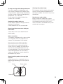
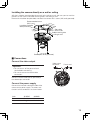
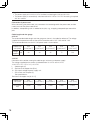
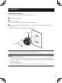
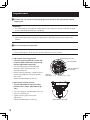
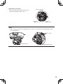
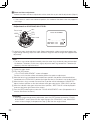
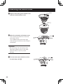
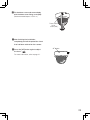
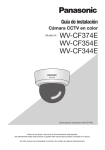
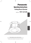
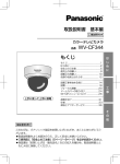
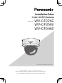
Installation Guide Color CCTV Camera Model No: WV-CF374E WV-CF354E WV-CF344E This illustration represents WV-CF344E. Before attempting to connect or operate this product, please read these instructions carefully and save this manual for future use. The model number is abbreviated in some descriptions in this manual. We declare under our sole responsibility that the product to which this declaration relates is in conformity with the standard or other normative document following the provisions of Directive 2004/108/EC. Vi deklarerar härmed vårt fulla ansvar för att den produkt till vilken denna deklaration hänvisar är i överensstämmelse med standarddokument eller annat normativt dokument som framställs i direktiv 2004/108/EC. Wij verklaren als enige aansprakelijke, dat het product waarop deze verklaring betrekking heeft, voldoet aan de volgende norm of ander normatief dokument, overeenkomstig de bepalingen van Richtlijn 2004/108/EC. Ilmoitamme yksinomaisella vastuullamme, että tuote, jota tämä ilmoitus koskee, noudattaa seuraavaa standardia tai muuta ohjeellista asiakirjaa, jotka noudattavat direktiivin 2004/108/EC säädöksiä. Vi erklærer os eneansvarlige for, at dette produkt, s o m d e n n e d e k l a r a t i o n o m h a n d l e r, e r i overensstemmelse med standard eller andre normative dokumenter i følge bestemmelserne i direktiv 2004/108/EC. Vi erklærer oss alene ansvarlige for at produktet som denne erklæringen gjelder for, er i overensstemmelse med følgende norm eller andre normgivende dokumenter som følger bestemmelsene i direktiv 2004/108/EC. CAUTION RISK OF ELECTRIC SHOCK DO NOT OPEN CAUTION: TO REDUCE THE RISK OF ELECTRIC SHOCK, DO NOT REMOVE COVER (OR BACK). NO USER-SERVICEABLE PARTS INSIDE. REFER SERVICING TO QUALIFIED SERVICE PERSONNEL. The lightning flash with arrowhead symbol, within an equilateral triangle, is intended to alert the user to the presence of uninsulated "dangerous voltage" within the product's enclosure that may be of sufficient magnitude to constitute a risk of electric shock to persons. The exclamation point within an equilateral triangle is intended to alert the user to the presence of important operating and maintenance (servicing) instructions in the literature accompanying the appliance. 2 WARNING: •To prevent fire or electric shock hazard, do not expose this apparatus to rain or moisture. •The apparatus should not be exposed to dripping or splashing and that no objects filled with liquids, such as vases, should be placed on the apparatus. •All work related to the installation of this product should be made by qualified service personnel or system installers. •To prevent injury, this apparatus must be securely attached to the floor/wall/ceiling in accordance with the installation instructions. •The installation shall be carried out in accordance with all applicable installation rules. •This product has no power switch. When turning off the power, turn off a Power Supply or remove a power cable. •The connections should comply with local electrical code. Contents Important safety instructions............................................................................................................ 4 Limitation of liability.......................................................................................................................... 5 Disclaimer of warranty..................................................................................................................... 5 Preface............................................................................................................................................ 6 About notations .............................................................................................................................. 6 Features ......................................................................................................................................... 6 About the user manuals................................................................................................................... 7 Trademarks and registered trademarks............................................................................................ 7 Precautions..................................................................................................................................... 8 Precautions for installation............................................................................................................. 10 Major operating controls and their functions.................................................................................. 12 Preparations.................................................................................................................................. 13 Remove the dome cover............................................................................................................. 13 About the side cable access hole ............................................................................................... 14 Installation method of camera..................................................................................................... 14 Connections................................................................................................................................ 15 Installation .................................................................................................................................... 17 Adjustment.................................................................................................................................... 18 Attaching the dome cover.............................................................................................................. 22 Setup menu................................................................................................................................... 24 List of setup menu...................................................................................................................... 24 Basic operation............................................................................................................................. 25 Screen transition diagram CF374 . ................................................................................................. 27 Screen transition diagram CF354 . ................................................................................................. 28 Screen transition diagram CF344 . ................................................................................................. 29 Troubleshooting ............................................................................................................................ 30 Specifications ............................................................................................................................... 31 Standard accessories ................................................................................................................... 32 3 Important safety instructions 1) Read these instructions. 2) Keep these instructions. 3) Heed all warnings. 4) Follow all instructions. 5) Do not use this apparatus near water. 6) Clean only with dry cloth. 7) Do not block any ventilation openings. Install in accordance with the manufacturer's instructions. 8) Do not install near any heat sources such as radiators, heat registers, stoves, or other apparatus (including amplifiers) that produce heat. 9) Protect the power cord from being walked on or pinched particularly at plugs, convenience receptacles, and the point where they exit from the apparatus. 10) Only use attachments/accessories specified by the manufacturer. 11) Use only with the cart, stand, tripod, bracket, or table specified by the manufacturer, or sold with the apparatus. When a cart is used, use caution when moving the cart/ apparatus combination to avoid injury from tip-over. S3125A 12) Refer all servicing to qualified service personnel. Servicing is required when the apparatus has been damaged in any way, such as power-supply cord or plug is damaged, liquid has been spilled or objects have fallen into the apparatus, the apparatus has been exposed to rain or moisture, does not operate normally, or has been dropped. 4 Limitation of liability THIS PUBLICATION IS PROVIDED "AS IS" WITHOUT WARRANTY OF ANY KIND, EITHER EXPRESS OR IMPLIED, INCLUDING BUT NOT LIMITED TO, THE IMPLIED WARRANTIES OF MERCHANTABILITY, FITNESS FOR ANY PARTICULAR PURPOSE, OR NON-INFRINGEMENT OF THE THIRD PARTY'S RIGHT. THIS PUBLICATION COULD INCLUDE TECHNICAL INACCURACIES OR TYPOGRAPHICAL ERRORS. CHANGES ARE ADDED TO THE INFORMATION HEREIN, AT ANY TIME, FOR THE IMPROVEMENTS OF THIS PUBLICATION AND/OR THE CORRESPONDING PRODUCT (S). Disclaimer of warranty IN NO EVENT SHALL Panasonic System Networks Co., Ltd. BE LIABLE TO ANY PARTY OR ANY PERSON, EXCEPT FOR REPLACEMENT OR REASONABLE MAINTENANCE OF THE PRODUCT, FOR THE CASES, INCLUDING BUT NOT LIMITED TO BELOW: (1) ANY DAMAGE AND LOSS, INCLUDING WITHOUT LIMITATION, DIRECT OR INDIRECT, SPECIAL, CONSEQUENTIAL OR EXEMPLARY, ARISING OUT OF OR RELATING TO THE PRODUCT; (2) PERSONAL INJURY OR ANY DAMAGE CAUSED BY INAPPROPRIATE USE OR NEGLIGENT OPERATION OF THE USER; (3) UNAUTHORIZED DISASSEMBLE, REPAIR OR MODIFICATION OF THE PRODUCT BY THE USER; (4) INCONVENIENCE OR ANY LOSS ARISING WHEN IMAGES ARE NOT DISPLAYED, DUE TO ANY REASON OR CAUSE INCLUDING ANY FAILURE OR PROBLEM OF THE PRODUCT; (5) ANY PROBLEM, CONSEQUENTIAL INCONVENIENCE, OR LOSS OR DAMAGE, ARISING OUT OF THE SYSTEM COMBINED BY THE DEVICES OF THIRD PARTY; (6) ANY CLAIM OR ACTION FOR DAMAGES, BROUGHT BY ANY PERSON OR ORGANIZATION BEING A PHOTOGENIC SUBJECT, DUE TO VIOLATION OF PRIVACY WITH THE RESULT OF THAT SURVEILLANCE-CAMERA'S PICTURE, INCLUDING SAVED DATA, FOR SOME REASON, BECOMES PUBLIC OR IS USED FOR ANY PURPOSE. 5 Preface This product is a 1/3-type CCD color CCTV camera. Connection of this product to a video monitor allows users to use this product as a monitoring camera. • WV-CF374E: with color / black-and-white mode switch function • WV-CF354E: with easy black-and-white mode switch function and focus adjustment function • WV-CF344E: with easy black-and-white mode switch function About notations The following notations are used when describing the functions limited for specific models. The functions without the notations are supported by all models. : The functions with this notation are available when using the model WV-CF374E. : The functions with this notation are available when using the model WV-CF354E. CF344 : The functions with this notation are available when using the model WV-CF344E. CF374 CF354 Features Introduction of newly developed high-resolution CCD The introduction of the newly developed CCD with 976 horizontal pixels has led to a horizontal resolution of as high as 650 TV lines. High sensitivity achieved because of noise reduction function Sensitivity at the following minimum illuminations has been accomplished for color images because of the introduction of low noise circuit design (Lens (built-in): F1.3): 0.08 lx (color), 0.008 lx (black-and-white) CF374 0.08 lx (color), 0.05 lx (black-and-white) CF354 CF344 Day/Night conversion function equipped CF374 No setup change is required at night because the image automatically changes from the color mode to the black-and-white mode at low illuminance. Bright images can be captured even at night because of automatic switching of IR filters at low illuminance. Focus adjustment function equipped CF354 Auto focus is achieved at installation of the camera or through menu operation. 6 Motion detection function (VMD) equipped The motion of an object is detectable. The acts of covering the camera with a cloth, a cap or other acts and changing the camera direction during surveillance can be detected. Note: • The VMD function is not the dedicated function to prevent thefts, fires, etc. We are not responsible for any accidents or damages caused by applying the function for the above purposes. About the user manuals The operating instructions of the camera consist of 2 sets: this book and operating instructions (PDF). This book explains how to install the camera. Refer to the "Operation Instructions (PDF)" on the provided CD-ROM for descriptions of how to perform the unit settings. Adobe® Reader® is required to read PDF. When the Adobe® Reader® is not installed on the PC, download the latest Adobe® Reader® from the Adobe web site and install it. Trademarks and registered trademarks Adobe, Acrobat Reader and Reader are either registered trademarks or trademarks of Adobe Systems Incorporated in the United States and/or other countries. 7 Precautions Refer installation work to the dealer. resulting in injury. Installation work requires technique and experiences. Otherwise injury or damage to this product may result. Be sure to consult the dealer. Install this product in a location high enough to avoid people and objects from bumping the product. Do not insert any foreign objects. Failure to observe this may cause a drop resulting in injury or accidents. This could permanetly damage this product. Turn the power off immediately and contact qualified service personnel for service. Do not strike or give a strong shock to this product. Failure to observe this may cause injury or fire. Do not attempt to disassemble or modify this product. Failure to observe this may cause fire or electric shock. Consult the dealer for the repair or inspections. Stop operation immediately when something is wrong with this product. When smoke goes up from this product or the smell of smoke comes from this product, continued use will result in fire, injury, or damage to the product. Turn the power off immediately and contact qualified service personnel for service. Select an installation area that can support the total weight. Selecting an inappropriate installation surface may cause the product to fall down or topple over, resulting in injury. Installation work shall be started after sufficient reinforcement. Periodic inspections shall be conducted. Rust on the metal parts or screws may cause the product to fall down resulting in injury or accidents. Consult the dealer for the inspections. This product shall be installed in a vibration-free place. 8 Failure to observe this may cause screws and bolts to be loosened and consequently to fall Turn the power off when do wiring of this product. Failure to observe this may cause electric shock. A short circuit or wrong wiring may cause fire. Do not use this product in an atmosphere of flammable gases. Failure to observe this may cause injury by explosion. Avoid installing this product in locations where it is subject to damage by salt or corrosive gas. Otherwise the mounting fixtures will deteriorate, causing the product to fall down and leading to accidents. Tighten screws and mounting fixtures to the specified torque. Failure to observe this may cause a drop resulting in injury or accidents. [Precautions for use] This product is designed to be used indoors. This product is not operable outdoors. This product has no power switch. When turning off the power, turn off a circuit breaker. To keep on using with stable performance Cleaning this product body Parts of this product may deteriorate and it may shorten the lifetime of this product when using in locations subject to high temperatures and high humidity. (Recommended operating temperature: +35 °C or lower) Do not expose this product to direct heat sources such as a heater. Turn the power off when cleaning this product. Do not use strong abrasive detergent when cleaning this product. Otherwise, it may cause discoloration. Handle this product with care. Do not drop this product, nor apply shock or vibration to this product. Failure to observe this may cause trouble. Synchronous mode setting Image synchronous mode of this camera indicates internal synchronization (INT) only. Set the multiplexed vertical drive (VD2) as OFF when the camera is connected to the system controller of the company. Do not touch the dome cover with your bare hands. A dirty dome cover causes deterioration of picture quality. Noise on monitor This product is equipped with a super sensitive CCD. Therefore, noise may appear on the monitor. This phenomenon is not trouble. Discoloration on the CCD color filter When continuously shooting a bright light source such as a spotlight, the color filter of the CCD may have deteriorated and it may cause discoloration. Even when changing the fixed shooting direction after continuously shooting a spotlight for a certain period, the discoloration may remain. Do not aim this product at strong light sources. A light source such as a spot light causes a blooming (light bleeding) or a smear (vertical lines). Smear Bright subject Blooming 9 Precautions for installation Panasonic assumes no responsibility for injuries or property damage resulting from failures arising out of improper installation or operation inconsistent with this documentation. This product is designed to be used indoors. This product is not operable outdoors. Do not expose the product to direct sunlight for hours and do not install the product near a heater or an air conditioner. Otherwise, it may cause deformation, discoloration and malfunction. Keep the product away from water and moisture. Installing place Avoid moist or dusty places to install this system. Otherwise, lifetime of the internal parts may be shortened. Contact your dealer for assistance if you are unsure of an appropriate place in your particular environment. • Make sure that the installation area is strong enough to hold the product, such as a concrete ceiling. • Install the camera in the foundation area of the architecture or where sufficient strength is assured. • If a ceiling board such as plaster board is too weak to support the total weight, the area shall be sufficiently reinforced. Avoid installing this product in a place with a high level of noise. Avoid installing this product in the following locations. Do not damage the power plug or cable. • Location where it may get wet from rain or water splash. • Locations where a chemical agent is used such as a swimming pool. • Locations subject to steam and oil smoke such as a kitchen. • Locations near flammable gas or vapor. • Locations where radiation or x-ray emissions are produced. • Locations where corrosive gas is produced, Locations where it may be damaged by briny air such as seashores. 10 • Locations where the temperature is not within –10 °C to +50 °C. • Locations subject to vibrations (This product is not designed for on-vehicle use.) • Locations subject to condensation as the result of severe changes in temperature (In case of installing the product in such locations, the dome cover may become foggy or condensation may be caused on the cover.) Installation near an air conditioner, an air cleaner, a vending machine, or the like causes noise. Avoid installing and connecting during a lightning storm. Otherwise, an electric shock or fire may be caused. Be sure to remove this product if it is not in use. Keep the camera cable away from the lighting cable. Failure to observe this may cause noise. Radio interference When the camera is used near TV/radio antenna, strong electric field or magnetic field (near a motor or a transformer), images may be distorted and noise sound may be produced. In such a case, run the camera cable through specialized steel conduit tubes. Locally procure the screws Screws are not supplied with this product. Prepare the screws according to the material, structure, strength and other factors of the mounting area and the total weight of objects to be mounted. Screw tightening • The screws and bolts must be tightened with an appropriate tightening torque according to the material and strength of the installation area. • Do not use an impact driver. Failure to observe this may cause overtightening and consequently damage to the screws. • When a screw is tightened, make the screw at a right angle to the surface. After tightening the screws or bolts, perform visual check to ensure tightening is enough and there is no backlash. 11 Major operating controls and their functions 1 2 3 4 5 ( & % $ # " 6 7 8 9 ) ! 1Video output connector Transmits composite video signals. 2Mark This mark is used when the dome cover is installed. 3Lens 4Focus knob (with lock function) CF374 CF344 Locks the focus position after focus adjustment. 5Zoom knob (with lock function) Locks the zoom position after zoom adjustment. 6Tilting lock screw Fixes the tilting position. 7AF button [AF] CF354 page 21. 8Setup button [SET] Press the [SET] button once and the “Focus Adjustment” screen will be displayed. CF374 CF344 Hold down the [SET] button for more than 2 seconds and the setup menu will be displayed. •[LEFT] / [RIGHT]: Press the [right] or [left ] button to move to the right or left in the menu, or change the displayed values. •[UP] / [DOWN]: Press the [up] or [down] button to move up or down in the menu. 12 (This illustration represents WV-CF344E.) •[SET]: Press this button in the menu to confirm the selected value or function. In addition, this button is used to open submenus. 9Adjustment monitor output jack Connect the adjustment monitor (small LCD monitor, etc.) to the adjustment monitor output jack to adjust the camera angle. @Panning table lock screw [LOCK] Locks the panning position after adjustment. AAzimuth adjuster Adjusts the azimuth angle of the camera. BTilting table Adjusts the tilting position of the camera. CPanning table Adjusts the panning position of the camera. DCable access hole EPower cord Supplies 24 V AC or 12 V DC from an external power source. FDust guard cap A rubber cap which prevent dust go into the camera through the cable access hole. GFingerplate This is where to put your fingers when removing the dome cover. Preparations When installing the camera on a wall or ceiling, there are three methods as specified below. • Use the one-gang junction box • Installing the camera directly on a wall or ceiling • Using the optional ceiling mount bracket WV-Q174E (for embedded installation on a ceiling) Important: • Procure 2 screws (M4) to secure the camera to a wall or ceiling according to the material of the installation area. Do not use wood screws and nails. For mounting a camera on a concrete wall or ceiling, use an anchor bolt (M4) for securing. (Recommended tightening torque M4: 1.6 N·m) • Required pull-out strength of a single screw/bolt is 196 N or more. • If a ceiling board such as plaster board is too weak to support the total weight, the installation area shall be sufficiently reinforced. • The protection sheet attached to the dome section should be peeled off after installation. The mounting conditions of the camera are described as follows: Installation place Applicable mount bracket Recommended screw Number of screw Minimum pull-out strength (per 1 pc.) Ceiling / wall One-gang junction box (locally procured) M4 2 pcs. 196 N Ceiling / wall (Direct mounting) M4 2 pcs. 196 N - *1 Ceiling WV-Q174E (approx. 310 g) - *1 Make sure that the installed mount bracket can support more than 5 times of the weight of the camera. Remove the dome cover 1 Peel off the protection sheet from the dome cover. Don't remove completely as this protects the dome during installation. 2 Loosen the dome cover fixing screw. 3 Adjust the mark on this unit to [|] on the dome cover, and turn the dome cover counterclockwise to remove it. Mark Mark [|] Note: • The clear dome cover and the inner dome are joined into a single unit. Therefore, never try to remove them. 13 About the side cable access hole If you choose not to drill hole in the wall or ceiling, but to wire the camera with the cable exposed, cut the cable access hole on the side of the dome cover to provide a cable entry. Side cable access hole Precautions when wiring from the side: • Remove the dust guard cap. Run the cable through the cable access hole and bend it inward, then reinstall the dust guard cap. • Move the cable to one side as shown. • Be careful not to pinch the cable with the dome cover. Installation method of camera Using a gang junction box (locally procured) When using a gang junction box (101.6 mm x 60.3 mm), procure one locally that meets the dimensions in the figure. Next locally procure 2 camera-mounting screws suitable for the installation surface and structure of the wall/ceiling or gang junction box. 1 Attach the gang junction box to the wall or ceiling. 2 Attach the camera to the gang junction box with the 2 screws (locally procured). 3 Tighten all mounting screws. 14 Installation mark 83.5 mm Screws (M4, locally procured) Gang junction box (locally procured) Installing the camera directly on a wall or ceiling Affix the installation template label (accessory) to the ceiling or wall, and use a pen to mark the positions of the screws and cable mounting hole in the ceiling or wall. Remove the installation template label, and attach the camera with 2 screws (M4, locally procured). Recommended screw (M4, 2 pcs.) Installation template label (accessory) 29 m m 83.5 mm Side cable m access hole 21 m Cable mounting hole in ceiling or wall Screws (M4, locally procured) Connections Connect the video output Important: Video output connector Power cord • Be sure to turn off the power of each device before connecting. • Be sure to secure the coaxial cable connectors. Connect a coaxial cable (locally procured) to the video output connector. Connect the power supply Connect the two-color conductor cable of the camera to the power supply. The colors and functions of the conductors are shown below. Color 12 V DC 24 V AC Brown Positive Live Blue Negative Neutral 15 Important: • The power supply of 24 V AC/12 V DC shall be insulated against 220 to 240 V AC. • The power supply is automatically switchover either 24 V AC or 12 V DC. No setting is required with this camera. Connection of power cord When connecting the power cord, use connectors that are designed for the power cord, and be careful not to let the power cord fall off. In addition, waterproofing work is needed at the joint, e.g., wrapping waterproof tape around the joint. Cable length and wire gauge 24 V AC The recommended cable length and wire gauge are shown in the table for reference. The voltage supplied to the power terminals of the camera should be within 19.5 V AC and 28 V AC. The recommended wire size for 24 V AC power cord is shown below: Copper wire size (AWG) #24 (0.205 mm2) #22 (0.325 mm2) #20 (0.519 mm2) #18 (0.833 mm2) #16 (1.307 mm2) Length (m) (approx.) 20 30 45 75 120 12 V DC Calculation of the relation among the cable length, resistance, and power supply. The voltage supplied to the camera shall be between 10.8 V DC and 16 V DC. 10.8 V DC ≤ VA - 2 (R x I x L) ≤ 16 V DC L :Cable length (m) R :Resistance of copper wire (Ω/m) VA:DC output voltage of power supply unit I :DC current consumption (A) See specifications. Resistance of copper wire [at 20 °C] 16 Copper wire size (AWG) #24 (0.205 mm2) #22 (0.325 mm2) #20 (0.519 mm2) #18 (0.833 mm2) #16 (1.307 mm2) Resistance Ω/m 0.083 0.052 0.033 0.020 0.013 Installation Installation of camera Turn off the power of all related devices before installation. 1 Remove the dome cover. 2 Connect all cables. If necessary, bind the cable with cable tie (locally procured). 3 Install the camera (The illustration below shows installation using a gang junction box (locally procured) ). Mount the camera with 2 screws (M4, locally procured). Installation mark Screws (M4, locally procured) Important: •Be sure to avoid twisting the cables when tightening the screws. Note: •When attached to the ceiling: Install the camera with its front (Model number indication face) facing the direction opposite to the “ TOP” arrow of the installation mark (“ FRONT” direction of the installation template label in the accessories). •When attached to the wall: Install the camera with the “ TOP” arrow of the installation mark facing upward. 17 Adjustment 1 Connect the ∅3.5 mm miniature plug (mono channel) to the adjustment monitor output jack. Important: • This video output is intended for confirmation of view angle, etc. during installation or repair service, and not for recording or monitoring. Note: • Video cannot be output through the video output cable after connecting the adjustment monitor. 2 Pan, tilt and azimuth adjustment Important: • When adjusting pan, tilt or azimuth, do not hold the lens of the camera. Original position mark 1 Adjustment of panning position Loosen the panning table lock screw and rotate the table to determine the panning position (adjustable range: 350°). • The panning position can be adjusted between +180° (clockwise) and –170° (counter-clockwise). • After the panning position is determined, fix the panning table with the panning table lock screw. (Recommended torque: 0.39 N·m) Panning table Panning table lock screw[LOCK] Counterclockwise: -170 º Clockwise: +180 º 2Adjustment of tilting position Turn the tilting table to adjust the tilting position of the camera. (adjustable range: ±90 °) • The view angle can be adjusted as the camera uses vari-focal lens. • Tighten the tilting lock screw after adjustment. (Recommended torque: 0.59 N·m) 18 Adjustable range: ±90 º 3Adjustment of azimuth Adjust the azimuth by rotating the azimuth azimuth adjuster adjuster. (adjustable range: ±100 °) Rotation angle: -100 º Rotation angle: +100 º Note: • Adjust azimuth so that the image top mark is facing “∆” to display the image properly rather than upside-down. TOP mark Image top mark Image top mark 19 3 Zoom and focus adjustment Perform the zoom and focus adjustments at the same time as pan and tilt adjustments (Step 2). Note: • If the camera is used in near-horizontal position, the shadow of the dome cover may appear in the image. <Adjustment on WV-CF344E, WV-CF374E> Focus knob NEAR WIDE Lens FAR TELE FOCUS ADJUSTMENT Zoom knob LOW HIGH ...................I INDICATOR 1135 PEAK HOLD 1135 BEST FOCUS 1 Loosen the zoom knob and focus knob. Select photographic subject and choose proper view angle through zooming. Adjust the zoom and focus rings to make the image clear (approximate adjustment). Note: •The focus may not be adjusted smoothly when the zoom ring is extremely close to the end of W direction (T direction). At this time, slightly adjust the zoom ring towards the T direction (W direction), and then adjust the focus. 2Tighten the zoom knob. 3Press the [SET] button. →The “FOCUS ADJUSTMENT” screen will appear. The focus assist function will be activated to perform the optimum adjustment. 4When the focus ring is positioned near the best focus position, the position will automatically be memorized as the "PEAK HOLD" position (the higher the value is, the closer it is to the focus point). 5When the focus ring is moved, the current focus position will be indicated on "INDICATOR". Adjust the focus position so that the indicator value goes close to the "PEAK HOLD" position. 6When the indicator value goes to the best focus position, "BEST FOCUS" will be displayed in reverse at the lower right corner of the screen. 7Press the [SET] button again to close the "FOCUS ADJUSTMENT" menu. (No operation for 3 minutes also closes the menu.) Important: • If the view angle changes during adjustment, press the [SET] button to close the “FOCUS ADJUSTMENT” screen (once the view angle changes, the “PEAKHOLD” and “INDICATOR” values will also change), and repeat from step 4 after the view angle is fixed. 20 Important: • When shooting in the following place or following subjects, press the [SET] button again to close the “FOCUS ADJUSTMENT” screen, or adjust to the best focus position while viewing the image. • Frequently moving subject • Subject with large illuminance change • Subject with low illuminance • Too bright or reflective subject • Subject through a window • Place where the lens easily becomes dirty • Subject with less contrast such as white wall • Subject with remarkable depth • Subject with heavy flicker • Subject with horizontally parallel lines such as a shutter <Adjustment on WV-CF354E> 1 Loosen the zoom knob and adjust to the best view angle between TELE and WIDE. Note: • The focus may not be adjusted smoothly when the zoom adjustment ring is extremely close to the end of W direction (T direction). At this time, slightly adjust the zoom adjustment ring towards the T direction (W direction), and then adjust the focus. 2Tighten the zoom knob. 3Rotate the front of the lens, and adjust to the best view angle between NEAR and FAR. 4Press the [AF ] button on the side of the camera, which will automatically focus. Note: •The AF function is not available over the entire focus range. Be sure to perform approxmate adjustment of the view angle before manual focusing, and then press the [AF] button to enable the AF function. •For the following subjects, select ELC control method, and then manually adjust the focus. • Fast-moving subject • Subject with significant illuminance change • Subject with low illuminance (such as high beam light) • Too bright or reflective subject • Subject behind a window • Less contrasty subject (such as white wall) • Subject with remarkable depth • Subject with flicker • Subject with parallel lines (such as a shutter) • Blurred or dirty spherical cover 21 Attaching the dome cover 1Align the mark with [|] on the dome cover, Mark and then install the dome cover. Mark [|] 2Adjust the orientation of the dome cover. Turn the enclosure clockwise so that the mark aligns with [||]. Turn the dome cover to the left or right while viewing the monitor so that the light is not blocked. Mark Important: •Be sure to align the mark with [||] when adjusting the dome cover. Do not apply excessive force, or you may cause damage. 3Turn the dome cover clockwise so that the mark aligns with [|||]. 22 Mark 4Fix the dome cover and camera body with the dome cover fixing screw (M3). (Recommended torque: 0.59 N · m) Dome cover fixing screw (M3) 5 After finishing the installation, completely peel off the protection sheet that had been retained on the camera. 6 Press the [AF] button again to adjust the focus. AF button CF354 For more information, refer to page 21. 23 Setup menu Performing each setting item in the setup menu should be completed in advance to use this unit. Perform the settings for each item in accordance with the conditions of the camera shooting area. List of setup menu Setup item Description CAMERA ID This item specifies the camera title. The camera title that indicates the camera location and other information about the camera is created with alphanumeric characters and symbol, and then displayed on the screen. Performs the camera operation settings. CAMERA SCENE 1/ SCENE 2 ALC/ELC Selects a scene file. It is possible to register and save the settings as a scene file in case that it is necessary to change the settings such when shooting at night. SHUTTER Specifies the electronic shutter speed. AGC Specifies gain adjustment. SENS UP Specifies electronic sensitivity enhancement. WHITE BAL Specifies white balance adjustment. DNR Selects the level of the digital noise reduction function. D&N (IR/ELE) Performs each setting regarding the black-and-white mode such as switching between color and black-and-white images. VMD Performs settings regarding VMD (Video Motion Detection) Selects the method of controlling the quantity of light in accordance with the lens to be used. Performs the settings regarding the camera system such as synchronization and privacy zone. SYSTEM Only INT method can be used; VD2 synchronization cannot be used. SYNC PRIVACY ZONE Hides undesired portions in the camera shooting area. STABILIZER Decides whether or not to enable the image stabilizer. EL-ZOOM Switches the electronic zoom on and off. UPSIDE-DOWN Flips the camera images vertically or horizontally. LDC Adjusts the lens distortion correction to convert the image so that it matches the square monitor. FOCUS CF354 Selects the adjustment method and fine adjustment method for focus. SPECIAL CHROMA GAIN Adjusts the chroma level (color density). AP GAIN Adjusts the aperture level. PEDESTAL Adjusts the pedestal (brightness) level. PIX OFF Corrects image defects such as flaws. CAMERA RESET Restores the settings in the setup menu to the default settings. SER.NO. Displays the serial number of this product. LANGUAGE 24 Selects a language to be used in the setup menu. Basic operation The operations in the setup menu are performed with the operation buttons after calling up the setup menu on the connected video monitor. The description below explains how to operate the setup menu basically. Screenshots of WV-CF354E are shown as an example. Screenshot 1 Hold down the [SET] button for about 2 seconds to call up the top screen of the setup menu. MODEL WV-CF354 CAMERA ID OFF CAMERA SYSTEM SPECIAL LANGUAGE END Step 1 Press the [up] or [down] button to move the cursor to "END". Step 2 Press the [right ] button to move the cursor to "SETUP", and press the [SET ] button to change the setup mode from "DISABLE" to "ENABLE". SETUP DISABIE Screenshot 2 The setup mode changes to "ENABLE", and the setup menu becomes ready to be set. Step 3 Move the cursor to the item to be set, and press the [SET] button. MODEL WV-CF354 CAMERA ID OFF CAMERA SYSTEM SPECIAL LANGUAGE END SETUP ENABLE 25 Screenshot 3 The selected setup screen in the setup menu appears on the screen. **CAMERA SETUP** SCENE1 ALC/ELC ALC SHUTTER OFF AGC ON(HIGH) SENS UP OFF WHITE BAL ATW1 DNR LOW D&N(ELE) OFF VMD OFF RET TOP END Step 4 Perform the settings for each item. • Selection of setting item: Press the [up] or [down] button to move the cursor. • Change of settings: Press the [right ] or [left ] button. • Display of advanced setup screen: Press the [SET] button when " " is attached to the target setting item. • Return to previous setup screen: Move the cursor to "RET" and press the [SET] button. Note: • If the top screen of the setup menu is called up with the operation buttons, the setup mode is always "DISABLE" to prevent operation errors. To perform settings in the setup menu, change the setup mode to "ENABLE". • The cursor is a reversely highlighted part. 26 • Return to the top screen: Move the cursor to "TOP" and press the [SET] button, to display the top screen of the setup menu. Step 5 Move the cursor to “END” and press the [SET ] button to return to the camera image screen, or wait about 5 minutes and the setup menu will automatically close. Screen transition diagram Top screen MODEL WV-CF374 CAMERA ID OFF CAMERA SYSTEM SPECIAL LANGUAGE CF374 "CAMERA ID" screen **CAMERA ID** 0123456789 ABCDEFGHIJKLM NOPQRSTUVWXYZ ().,'":;&#!?= +-*/%$ SPACE POSI RET TOP END RESET END SETUP DISABLE ................ "CAMERA SETUP" screen **CAMERA SETUP** SCENE1 ALC/ELC ALC SHUTTER OFF AGC ON(HIGH) SENS UP OFF WHITE BAL ATW1 DNR HIGH D&N(IR) AUTO1 VMD OFF RET TOP END "SYSTEM SETUP" screen **SYSTEM SETUP** SYNC INT PRIVACY ZONE OFF STABILIZER OFF EL-ZOOM OFF UPSIDE-DOWN OFF LDC I...... 0 + RET TOP END "SPECIAL SETUP" screen **SPECIAL SETUP** ....I..160 CHROMA GAIN ...I... 32 AP GAIN .I..... 15 PEDESTAL + PIX OFF CAMERA RESET PUSH SET SER.NO. XXXXXXXX RET TOP END "LANGUAGE SETUP" screen **LANGUAGE SETUP** LANGUAGE ENGLISH SET RET TOP END 27 Screen transition diagram Top screen MODEL WV-CF354 CAMERA ID OFF CAMERA SYSTEM SPECIAL LANGUAGE END SETUP DISABLE CF354 "CAMERA ID" screen **CAMERA ID** 0123456789 ABCDEFGHIJKLM NOPQRSTUVWXYZ ().,'":;&#!?= +-*/%$ SPACE POSI RET TOP END RESET ................ "CAMERA SETUP" screen **CAMERA SETUP** SCENE1 ALC/ELC ALC SHUTTER OFF AGC ON(HIGH) SENS UP OFF WHITE BAL ATW1 DNR HIGH D&N(ELE) OFF VMD OFF RET TOP END "SYSTEM SETUP" screen **SYSTEM SETUP** SYNC INT PRIVACY ZONE OFF STABILIZER OFF EL-ZOOM OFF UPSIDE-DOWN OFF LDC I...... 0 + FOCUS ABF PUSH RET TOP END "SPECIAL SETUP" screen **SPECIAL SETUP** ....I..160 CHROMA GAIN ...I... 32 AP GAIN .I..... 15 PEDESTAL + PIX OFF CAMERA RESET PUSH SET SER.NO. XXXXXXXX RET TOP END "LANGUAGE SETUP" screen **LANGUAGE SETUP** LANGUAGE SET RET TOP END 28 ENGLISH Screen transition diagram Top screen MODEL WV-CF344 CAMERA ID OFF CAMERA SYSTEM SPECIAL LANGUAGE END SETUP DISABLE CF344 "CAMERA ID" screen **CAMERA ID** 0123456789 ABCDEFGHIJKLM NOPQRSTUVWXYZ ().,'":;&#!?= +-*/%$ SPACE POSI RET TOP END RESET ................ "CAMERA SETUP" screen **CAMERA SETUP** SCENE1 ALC/ELC ALC SHUTTER OFF AGC ON(HIGH) SENS UP OFF WHITE BAL ATW1 DNR HIGH D&N(ELE) OFF VMD OFF RET TOP END "SYSTEM SETUP" screen **SYSTEM SETUP** SYNC INT PRIVACY ZONE OFF STABILIZER OFF EL-ZOOM OFF UPSIDE-DOWN OFF LDC I...... + 0 RET TOP END "SPECIAL SETUP" screen **SPECIAL SETUP** ....I..160 CHROMA GAIN ...I... 32 AP GAIN .I..... 15 PEDESTAL + PIX OFF CAMERA RESET PUSH SET SER.NO. XXXXXXXX RET TOP END "LANGUAGE SETUP" screen **LANGUAGE SETUP** LANGUAGE ENGLISH SET RET TOP END 29 Troubleshooting Before asking for repairs, confirm the causes with the following table. Contact your dealer if a problem cannot be solved even after checking and trying the solution in the table or a problem is not described below. Symptom Cause/solution •Are the power cord and coaxial cable connected appropriately? →Check whether the connection is appropriately established. •Is the adjustment monitor connected? → Confirm whether the monitor is connected. No image displayed Blurred image Black line in image Reference page 15-16 18 •Is the monitor brightness appropriately adjusted, or is the contrast appropriately adjusted? → Check whether the monitor settings are appropriate. – •Is the cushioning material in the spherical cover removed? → Confirm whether the cushioning material has been removed. – •Is the spherical cover dirty or damaged? → Verify the state of the spherical cover. – •Is the focus adjusted correctly? → Check if the focus is adjusted correctly. 20-21 •Is the lens of the camera soiled with dirt or dust? → Check whether the lens of the camera is clean. – •Is the connected system controller set to multiplexed vertical drive (VD2)? → Check whether the connected system controller is set correctly. 9 •The power cord or connector is damaged. Continuous use of the damaged cord or connector may cause electric shock or fire. Turn off the power supply immediately and request repair from your dealer. – Damaged power cord sheathing Heated portion of power line consisting of power cord and connector during use The temperature of power cord rises or falls when the power cord is bent or stretched during use 30 Specifications WV-CF374E WV-CF354E WV-CF344E 24 V AC 50/60 Hz, 12 V DC 24 V AC: 2.1 W, 12 V DC: 180 mA 1/3-type interline transfer CCD 976 (H)×582 (V) 4.8 mm (H)×3.6 mm (V) 2:1 interlace 625 lines 15.625 kHz 50.00 Hz Internal (INT) 650 TV lines 400 TV lines 1.0 V [p-p] PAL composite video signal 75 52 dB (AGC OFF) 0.08 lx (color mode) Minimum illumination 0.008 lx 0.05 lx (black-and-white mode) (black-and-white mode) Lens 3.6x vari-focal lens Focal length 2.8 mm to 10.0 mm F1.3 (WIDE)to F3.1 (TELE) F1.3 (WIDE)to F3.0 (TELE) F1.3 (WIDE)to F3.1 (TELE) Aperture ratio WIDE (H×V) 100.8°×73.8° WIDE (H×V) 100.3°×73.4° WIDE (H×V) 100.3°×73.5° View angle TELE (H×V) 27.6°×20.7° TELE (H×V) 27.8°×20.9° TELE (H×V) 27.6°×20.7° Pan:+180 ° to –170 ° Adjustable angle range Tilt:±90 ° Azimuth:±100 ° Ambient operating temperature –10 °C to +50 °C Ambient operating humidity Less than 90 % Dimensions ø108 mm × 94 mm (H) Mass 320 g Chinese: up to 8 characters; English letter, numbers and symbols: up Camera title to 16 characters. Light control mode setting ALC/ALC+/ELC Back light compensation ON/OFF Auto black stretch (ABS) ON/OFF OFF (1/50), 1/120, 1/250, 1/500, 1/1000, 1/2000, 1/4000, 1/10000, 1/120000 (s) Shutter speed Auto gain control ON (HIGH/MID/LOW), OFF OFF/AUTO (×2, ×4, ×6, ×10, ×16, ×32) /FIX (×2, ×4, ×6, ×10, ×16, Sensitivity up ×32, ×64, ×128, ×256, ×512) White balance ATW1/ATW2/AWC Digital noise reduction LOW/HIGH Power source Power consumption Image sensor Effective pixels Scanning area Scanning system Scanning line Horizontal scanning frequency Vertical scanning frequency Synchronization Horizontal resolution Vertical resolution Video output Signal-to-noise ratio 31 Day&Night (IR) Day&Night (Electric) Video motion detection Number of scene file Privacy zone Image stabilizer Electronic zoom Upside-down Lens distortion correction Focus CF354 WV-CF374E WV-CF354E AUTO1/AUTO2/ON/OFF CF374 AUTO/OFF CF354 CF344 OFF/Motion Detection /Scene Change 2 ON (1)/ON (2)/OFF ON/OFF ON (up to 2x)/OFF ON/OFF 0 to 255 ABF/MANUAL WV-CF344E Values of weight and dimensions are approximate. The specification is subject to change without notice. Standard accessories CD-ROM*............................................................. 1 pc. Installation Guide(this book).................................. 1 pc. *The CD-ROM contains the operating installations and installation guide (PDF). The following is used during installation procedures: Installation template label...................................... 1 pc. 32 Information on Disposal for Users of Waste Electrical & Electronic Equipment (private households) This symbol on the products and/or accompanying documents means that used electrical and electronic products should not be mixed with general household waste. For proper treatment, recovery and recycling, please take these products to designated collection points, where they will be accepted on a free of charge basis. Alternatively, in some countries you may be able to return your products to your local retailer upon the purchase of an equivalent new product. Disposing of this product correctly will help to save valuable resources and prevent any potential negative effects on human health and the environment which could otherwise arise from inappropriate waste handling. Please contact your local authority for further details of your nearest designated collection point. Penalties may be applicable for incorrect disposal of this waste, in accordance with national legislation. For business users in the European Union If you wish to discard electrical and electronic equipment, please contact your dealer or supplier for further information. Information on Disposal in other Countries outside the European Union This symbol is only valid in the European Union. If you wish to discard this product, please contact your local authorities or dealer and ask for the correct method of disposal. 33 34 35 Panasonic Corporation http://panasonic.net Importer's name and address to follow EU rules: Panasonic Testing Centre Panasonic Marketing Europe GmbH Winsbergring 15, 22525 Hamburg F.R.Germany © Panasonic System Networks Co., Ltd. 2012 sC1211-3052 PGQX1143WA Printed in China