1
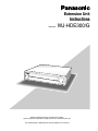
Extension Unit
Instructions
Model No.
WJ-HDE300/G
Extensio
n Unit
WJ-HDE
300
Before attempting to connect or operate this product,
please read these instructions carefully and save this manual for future use.
The model number is abbreviated in some descriptions in this manual.
We declare under our sole responsibility that the product to which this
declaration relates is in conformity with the standards or other normative
documents following the provisions of Directives 2006/95/EC and
2004/108/EC.
Wij verklaren als enige aansprakelijke, dat het product waarop deze
verklaring betrekking heeft, voldoet aan de volgende normen of andere
normatieve documenten, overeenkomstig de bepalingen van Richtlijnen
2006/95/EC en 2004/108/EC.
Wir erklären in alleiniger Verantwortung, daß das Produkt, auf das sich
diese Erklärung bezieht, mit den folgenden Normen oder normativen
Dokumenten übereinstimmt. Gemäß den Bestimmungen der Richtlinie
2006/95/EC und 2004/108/EC.
Vi erklærer os eneansvarlige for, at dette produkt, som denne deklaration
omhandler, er i overensstemmelse med standarder eller andre normative
dokumenter i følge bestemmelserne i direktivene 2006/95/EC og
2004/108/EC.
Nous déclarons sous notre propre responsabilité que le produit auquel se
réfère la présente déclaration est conforme aux normes spécifiées ou à tout
autre document normatif conformément aux dispositions des directives
2006/95/CE et 2004/108/CE.
Vi deklarerar härmed vårt fulla ansvar för att den produkt till vilken denna
deklaration hänvisar är i överensstämmelse med de standarder eller andra
normativa dokument som framställs i direktiv nr 2006/95/EC och
2004/108/EC.
Nosotros declaramos bajo nuestra única responsabilidad que el producto a
que hace referencia esta declaración está conforme con las normas u otros
documentos normativos siguiendo las estipulaciones de las directivas
2006/95/CE y 2004/108/CE.
Ilmoitamme yksinomaisella vastuullamme, että tuote, jota tämä ilmoitus
koskee, noudattaa seuraavia standardeja tai muita ohjeellisia asiakirjoja,
jotka noudattavat direktiivien 2006/95/EC ja 2004/108/EC säädöksiä.
Noi dichiariamo sotto nostra esclusiva responsabilità che il prodotto a cui si
riferisce la presente dichiarazione risulta conforme ai seguenti standard o
altri documenti normativi conformi alle disposizioni delle direttive
2006/95/CE e 2004/108/CE.
Vi erklærer oss alene ansvarlige for at produktet som denne erklæringen
gjelder for, er i overensstemmelse med følgende normer eller andre
normgivende dokumenter som følger bestemmelsene i direktivene
2006/95/EC og 2004/108/EC.
For U.K.
WARNING:
• To prevent fire or electric shock hazard, do not expose this appliance to
rain or moisture. The apparatus shall not be exposed to dripping or
splashing and that no objects filled with liquids, such as vases, shall be
placed on the apparatus.
• All work related to the installation of this product should be made by
qualified service personnel or system installers.
• For PERMANENTLY CONNECTED APPARATUS provided neither with
an all-pole MAINS SWITCH nor an all-pole circuit breaker, the installation shall be carried out in accordance with all applicable installation
rules.
CAUTION:
• Read the label
on the rear of the unit for identification of this product,
and the power ratings.
CAUTION
RISK OF ELECTRIC SHOCK
DO NOT OPEN
CAUTION: TO REDUCE THE RISK OF ELECTRIC SHOCK,
DO NOT REMOVE COVER (OR BACK).
NO USER-SERVICEABLE PARTS INSIDE.
REFER SERVICING TO QUALIFIED SERVICE PERSONNEL.
The lightning flash with arrowhead symbol,
within an equilateral triangle, is intended to
alert the user to the presence of uninsulated
"dangerous voltage" within the product's
enclosure that may be of sufficient magnitude to constitute a risk of electric shock to
persons.
The exclamation point within an equilateral
triangle is intended to alert the user to the
presence of important operating and maintenance (servicing) instructions in the literature accompanying the appliance.
Power disconnection. Unit with or without ON-OFF switches
have power supplied to the unit whenever the power cord is
inserted into the power source; however, the unit is operational
only when the ON-OFF switch is in the ON position. The power
cord is the main power disconnect for all units.
FOR YOUR SAFETY PLEASE READ THE FOLLOWING TEXT CAREFULLY.
This appliance is supplied with a moulded three pin mains plug for your
safety and convenience.
A 5 amp fuse is fitted in this plug.
Should the fuse need to be replaced please ensure that the replacement
fuse has a rating of 5 amp and that it is approved by ASTA or BSI to
BS1362.
or the BSI mark
on the body of the
Check for the ASTA mark
fuse.
If the plug contains a removable fuse cover you must ensure that it is
refitted when the fuse is replaced.
If you lose the fuse cover the plug must not be used until a replacement
cover is obtained.
A replacement fuse cover can be purchased from your local Panasonic
Dealer.
H
IF THE FITTED MOULDED PLUG IS UNSUITABLE FOR THE SOCKET OUTLET IN YOUR HOME THEN THE FUSE SHOULD BE
REMOVED AND THE PLUG CUT OFF AND DISPOSED OF SAFELY.
THERE IS A DANGER OF SEVERE ELECTRICAL SHOCK IF THE
CUT OFF PLUG IS INSERTED INTO ANY 13 AMP SOCKET.
If a new plug is to be fitted please observe the wiring code as shown
below.
If in any doubt please consult a qualified electrician.
WARNING: This apparatus must be earthed.
IMPORTANT
The wires in this mains lead are coloured in accordance with the following code.
Green-and-yellow:
Earth
Blue:
Neutral
Brown:
Live
As the colours of the wire in the mains lead of this appliance may not
correspond with the coloured markings identifying the terminals in your
plug, proceed as follows.
The wire which is coloured green-and-yellow must be connected to
the terminal in the plug which is marked with the letter E or by the earth
symbol I or coloured green or green-and-yellow.
The wire which is coloured blue must be connected to the terminal in
the plug which is marked with the letter N or coloured black.
The wire which is coloured brown must be connected to the terminal
in the plug which is marked with the letter L or coloured red.
How to replace the fuse
Open the fuse compartment with
a screwdriver and replace the fuse
and fuse cover.
FUSE
The serial number of this product may be found on the rear
of the unit.
You should note the serial number of this unit in the space
provided and retain this book as a permanent record of your
purchase to aid identification in the event of theft.
Model No.
Serial No.
2
G
WJ-HDE300
■ Important Safety Instructions
1) Read these instructions.
2) Keep these instructions.
3) Heed all warnings.
4) Follow all instructions.
5) Do not use this apparatus near water.
6) Clean only with dry cloth.
7) Do not block any ventilation openings. Install in accordance with the manufacturer's instructions.
8) Do not use near any heat sources such as radiators, heat registers, stoves, or other apparatus (including amplifiers) that
produce heat.
9) Do not defeat the safety purpose of the polarized or grounding-type plug. A polarized plug has two blades with one wider
than the other. A grounding-type plug has two blades and a third grounding prong. The wide blade or the third prong are
provided for your safety. If the provided plug does not fit into your outlet, consult an electrician for replacement of the
obsolete outlet.
10) Protect the power cord from being walked on or pinched particularly at plugs, convenience receptacles and the points
where they exit from the apparatus.
11) Only use attachments/accessories specified by the manufacturer.
12) Use only with the cart, stand, tripod, bracket, or table specified by the manufacturer, or sold with the apparatus. When a
cart is used, use caution when moving the cart/apparatus combination to avoid injury from tip-overs.
S3125A
13) Unplug this apparatus during lightning storms or when unused for long periods of time.
14) Refer all servicing to qualified service personnel. Servicing is required when the apparatus has been damaged in any way,
such as power-supply cord or plug is damaged, liquid has been spilled or objects fallen into the apparatus, the apparatus
has been exposed to rain or moisture, does not operate normally, or has been dropped.
3
Contents
■ Important Safety Instructions . . . . . . . . . . . . . . . . . . . . . . . . . . . . . . . 3
■ General . . . . . . . . . . . . . . . . . . . . . . . . . . . . . . . . . . . . . . . . . . . . . . . 5
■ Precautions . . . . . . . . . . . . . . . . . . . . . . . . . . . . . . . . . . . . . . . . . . . . 5
■ Appearance . . . . . . . . . . . . . . . . . . . . . . . . . . . . . . . . . . . . . . . . . . . . 6
● Front View . . . . . . . . . . . . . . . . . . . . . . . . . . . . . . . . . . . . . . . . . . . 6
● Rear View . . . . . . . . . . . . . . . . . . . . . . . . . . . . . . . . . . . . . . . . . . . . 7
● Inside the Front Lid . . . . . . . . . . . . . . . . . . . . . . . . . . . . . . . . . . . . 8
■ Replacing/Mounting HDDs . . . . . . . . . . . . . . . . . . . . . . . . . . . . . . . . 9
● Procedures . . . . . . . . . . . . . . . . . . . . . . . . . . . . . . . . . . . . . . . . . . 9
■ Mounting in a Rack . . . . . . . . . . . . . . . . . . . . . . . . . . . . . . . . . . . . . . . 12
● Unit Layout . . . . . . . . . . . . . . . . . . . . . . . . . . . . . . . . . . . . . . . . . . . 12
● How to Mount . . . . . . . . . . . . . . . . . . . . . . . . . . . . . . . . . . . . . . . . . 13
■ Connections . . . . . . . . . . . . . . . . . . . . . . . . . . . . . . . . . . . . . . . . . . . . 14
● Procedures . . . . . . . . . . . . . . . . . . . . . . . . . . . . . . . . . . . . . . . . . . 14
■ Setup Procedures . . . . . . . . . . . . . . . . . . . . . . . . . . . . . . . . . . . . . . . 15
● Basic Setups . . . . . . . . . . . . . . . . . . . . . . . . . . . . . . . . . . . . . . . . . 15
● Replacement & Setup in the SINGLE mode . . . . . . . . . . . . . . . . . 19
● Changing Setups . . . . . . . . . . . . . . . . . . . . . . . . . . . . . . . . . . . . . 20
● Recovery of RAID5 Disk . . . . . . . . . . . . . . . . . . . . . . . . . . . . . . . . 22
● Unit Number Check . . . . . . . . . . . . . . . . . . . . . . . . . . . . . . . . . . . . 26
■ Troubleshooting . . . . . . . . . . . . . . . . . . . . . . . . . . . . . . . . . . . . . . . . . 27
■ Specifications . . . . . . . . . . . . . . . . . . . . . . . . . . . . . . . . . . . . . . . . . . . 28
■ Accessories . . . . . . . . . . . . . . . . . . . . . . . . . . . . . . . . . . . . . . . . . . . . 28
4
■ General
The extension unit WJ-HDE300 can accommodate up to four hard disk drives per unit to add available disk space to the digital
disk recorder WJ-HD316A/WJ-HD309A series. Up to seven extension units can be connected to a digital disk recorder. The
units can be operated in RAID level 5* mode for high tolerance to disk error.
* RAID level 5 (Redundant Arrays for Independent Disks, independent data disks with distributed parity blocks)
RAID level 5 regards 3 or more drives as one drive, and it is possible to read data by automatically attaching error correction data even though one of the drives is broken. (It is impossible to read data if 2 or more drives are broken.)
RAID level 5 requires a minimum of 3 drives per unit.
When using the RAID function, the logical disk size of the extension unit will be as below.
Logical disk size = Smallest size of the disk among the disks in the extension unit x (Number of the disks in the extension
unit - 1) The actual space may be several percent lower than the logical space.
Even when the total capacity of HDD mounted on each extension unit is more than 2 TB, the capacity that is actually available will be 2 TB or less.
* Important
When set to RAID level 5, the digital disk recorder will not access the HDD preinstalled in it, but will access only the HDDs
in the extension unit.
■ Precautions
• Do not operate the appliance beyond its specified temperature, humidity or power source ratings.
Do not use the appliance in an extreme environment
where a high temperature or high humidity exists. Use
the appliance at temperatures within +5 °C to +45 °C
(41 °F to 113 °F) and humidity below 85 %.
The input power source for this appliance is 220 V AC –
240 V AC 50 Hz.
• Avoid shock and vibration
Shock or vibration may damage the HDD.
The HDDs are fragile especially when the HDD motors
are revolving and the HDD POWER indicator lights. Be
sure to turn off either switch: the POWER switch on the
rear panel, or the HDD POWER switch inside the front
lid: before you mount the unit into a rack or dismount it.
Do not move the HDD for 30 seconds after turning off
the power.
• Pay attention to static electricity
Put your hand on a metallic surface to discharge static
electricity before installation.
Do not touch components mounted on the HDD directly
with your hand.
Hold only the two sides of the HDD when installing.
• Avoid condensation on the surface of the HDD.
If this happens, do not turn on the power of the appliance and leave the appliance for around 2 hours.
Wait until the dew evaporates in any of the following
cases.
• The appliance is moved to a place significantly different in temperature or humidity.
• The appliance is moved out from an air-conditioned
room.
• The appliance is placed in an extremely humid
place.
• The appliance is placed in a room where a heater
has just been turned on.
• Consumable parts
Contact your dealer about replacement when the time
comes.
A hard disk drive needs replacing after a certain length
(depends on the model) of operation.
Cooling fans also need replacing after around
20 000 - 30 000 hours of operation.
• Do not block the ventilation opening or slots on the
cover.
To prevent the appliance from overheating, place it at
least 5 cm (2 inches) away from the wall.
• Avoid placing the unit on an inclined surface.
Otherwise, malfunction or damage to the disk may
occur. Place the unit in a horizontal position.
5
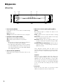
■ Appearance
● Front View
q
we
r
t
ERROR
HDD
POWER
HDD 1
HDD 2
HDD 3
HDD 4
OPERATE
Extension Unit
WJ-HDE
q Error indicator [ERROR]
Lights when an error occurs. Refer to Troubleshooting
for details.
Red: System error
Orange: Thermal error or malfunction of the cooling fan.
w HDD power indicator [HDD POWER]
ON: Indicates that the HDDs are powered.
OFF: Indicates that the HDDs are not powered.
Notes:
• Do not move or shock the unit while this indicator is
lit. Otherwise, the HDDs will be damaged.
• This indicator will light and go out by the setting of
the HDD POWER switch inside the front lid of the
unit, or by the operation on the HDD SAFETY MENU
of the digital disk recorder.
e Operate indicator [OPERATE]
Lights green when turning on the power switch on the
rear panel.
r HDD access indicators [HDD 1] [HDD 2] [HDD 3]
[HDD 4]
Each indicator lights to indicate the status of the
respective HDD.
Green: Indicates that the respective HDD is running
normally.
Red: Indicates that the respective HDD is the first faulty
drive among the HDDs in the unit.
Red blink: Indicates that the respective HDD is the
second or subsequent faulty drive among the HDDs
in the unit.
Orange-red alternate blink/Orange: Indicates that the
respective drive is currently being recovered in
RAID level 5 mode.
These indicators normally show the status of the
respective drive, but they work as a set when a system
error occurs. Refer to Troubleshooting for further information.
Important
When one of the indicators lights red, replace the
respective HDD immediately. If two or more indicators
light/blink red, it will be impossible to recover data.
There may be cases where it is eventually impossible to
recover data if two drives are coincidentally damaged
or the second drive fails during the data recovery
process.
t Front cover
Detach the front cover when it is necessary to install
HDDs or to operate the switches inside the unit.
6
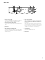
● Rear View
y u
i
i
o
SIGNAL GND
!0
POWER
EXT
IN
OUT
2
AC IN
1
!1
!2
y Serial in connector [IN]
Connect the WJ-HD300 series digital disk recorder or
other extension unit with the supplied serial cable.
u Serial out connector [OUT1] [OUT2]
Connect another extension unit with the supplied serial
cable.
i Cooling fan
o Signal GND terminal [SIGNAL GND]
Connect this terminal if required, to the SIGNAL GND
terminal of other equipment to avoid a possible grounding loop and noise.
!0 Power switch [POWER]
Turn on the power of the unit with this switch before
turning on the power of the digital disk recorder, or turn
them on simultaneously. Otherwise, the HDDs will not
be mounted.
When turning off the power of the unit with this switch,
turn off the power of the digital disk recorder first, and
then turn off the power of this unit after confirming that
all HDD access indicators are not lit or blinking.
!1 AC inlet [AC IN]
Connect the supplied power cord.
!2 Cable clamp
7
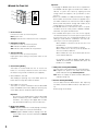
● Inside the Front Lid
q’
!3
MODE
w’
!4
e’
RESET
!5
!6
SINGLE RAID5
HDD POWER
OFF
ON
RECOVER
q' Error indicators
Functions the same as on the front panel.
Red: System error
Orange: Thermal error or malfunction of the cooling fan.
w' HDD power indicator
Functions the same as on the front panel.
ON: Indicates that HDDs are powered.
OFF: Indicates that the HDDs are not powered.
e' Operate indicator
Functions the same as on the front panel.
Lights green when turning on the power switch on the
rear panel.
!3 Reset button [RESET]
This button is located inside the unit. To access this
button, it is necessary to detach the front cover. Press
this button using a small screw driver (not supplied).
• When SINGLE is selected
After adding or replacing any of the HDDs, press this
button. Refer to Setup Procedures for details.
• When RAID 5 is selected
This button is used in combination with the RECOVER
button and MODE switch after adding or replacing any
of the HDDs. Refer to Setup Procedures for details.
Important
Do not press the RESET button and the RECOVER
button simultaneously when SINGLE is selected.
Otherwise, the setting of the digital disk recorder
may be initialized and it may cause a malfunction.
!4 Mode switch [MODE]
RAID 5: Applies RAID level 5 mode (striping at the byte
level also stripe error correction information).
SINGLE: Applies SINGLE mode (no striping across drives for data or error correction information). Default
position
8
Important
• Changing the MODE switch will not be accepted when
the ERROR indicator lights red and/or when HDD 1-4
indicate a system error status by lighting red and
orange. When this happens, ask your dealer to solve
the error.
• When set to RAID5, the HDD preinstalled in the digital
disk recorder will not work. Instead, it is applied only to
the HDDs installed in the extension unit and the digital
disk recorder will perform storage and readout of the
image data by accessing the extension unit.
• The MODE switches of all extension units in a system
should be set to the same position, SINGLE or RAID5.
Otherwise, the system will malfunction.
• The available disk space of the unit can be logically
calculated as follows. The actual space may be several
percent lower than you calculated depending on the
HDD type used and their combination. The most efficient way is to use the same type drives.
When SINGLE is selected, it will be the sum of all
the HDD sizes.
When RAID 5 is selected, it will be as follows.
When 3 HDDs are in the unit: It will be double the
size of the smallest HDD size.
When 4 HDDs are in the unit: It will be triple the size
of the smallest HDD size.
For example, if 4 HDDs of 80 GB, 120 GB, and two
160 GB are mounted, the available disk space will
be 80 G x 3 = 240 GB.
!5 HDD power switch [HDD POWER]
Use this switch in the ON position for normal operation.
ON: Supplies the power to the HDDs and the HDD
power indicators will light. Default position
OFF: Does not supply the power and the HDD power
indicators will go out.
!6 Recover button [RECOVER]
Use this button with the RESET button after replacing
the HDDs used in the RAID 5 mode to start data recovery.
Refer to page 12 for details.
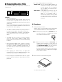
■ Replacing/Mounting HDDs
Up to four HDDs (locally procured) can be installed in an
extension unit.
HDD 2
HDD 4
HDD 1
HDD 3
Important
• Type of hard disk drive
Consult your dealer about hard disk drives. Use only
hard disk drives compatible with the extension unit. If
unauthorized hard disk drives are used, it may cause a
system error.
It is recommended that the same type drives having the
same capacity should be installed in the extension units
to maximize the usable capacity.
• The HDDs should be installed in the proper positions in
the order as shown above. Do not skip or reverse the
order of the HDD positions. Otherwise, the recorder will
not recognize the extension unit or wrongly mounted
drives.
• The replaced/added HDDs will be formatted.
SINGLE mode: Only the replaced/added HDD will be
formatted. For example, when the HDD
4 of the extension unit 2 is replaced,
only the HDD4 of the extension unit 2
will be formatted.
RAID 5 mode: All the HDDs of the extension units will
be formatted when a new HDD is
added or a preinstalled HDD is
removed. For example, when the HDD
4 of the extension unit 2 is added, all
the HDDs of the extension unit 2 will be
formatted.
● Procedures
1.
HDD power-off procedures
Perform either of the following procedures depending
on the installation situations to stop the HDD motors.
Case 1: When the rear of the units is accessible, turn off
the power switches of the digital disk recorder
first, and turn off extension units.
• The MODE switches of all units in a system should be
set to the same position, SINGLE or RAID5. When
mixed, it will cause a system error. See Troubleshooting
for details.
• When applying the RAID5 mode, it requires a minimum
of 3 drives per unit. When only two drives are mounted
in position #1 and #2, the ERROR indicator will be lit
red, HDD3 indicator will blink red, and HDD4 indicator
will be lit red.
• When applying the RAID5 mode, the digital disk
recorder will not access the HDD preinstalled in it, but
will access only the HDDs in the extension unit.
• Do not change the installed positions after the system
has been operated. Otherwise, data readout will not be
performed
POWER
Case 2: When the rear of the units is inaccessible, for
example when mounted in a rack, open the
SETUP MENU of the digital disk recorder and set
the HDD SAFETY MODE to ON. The extension
units will turn to the HDD power-off mode.
Refer to Setup Procedures of this manual and the
Operating Instructions included with the digital
disk recorder for details .
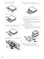
2.
Detach the front cover and the front panel.
2-1
2-1 Remove the two screws.
9
2-2 Slide the front cover to the left.
2-3 Pull the front cover toward you.
3.
Remove two of the HDD mounting brackets.
• Remove the four screws and pull the brackets toward
you.
2-3
2-2
2-3
2-4 Disconnect the harness.
2-4
• When replacing an HDD, remove it from the bracket.
4.
Prepare the HDDs to be fixed on the brackets.
• Release the static electricity from your body before
touching the HDDs.
• Put the conductive bag (in which the HDD was packed)
on a soft surface and place the HDD on it with the circuit board side down.
2-5 Remove the six screws (marked with ∆) and detach
the thin metal plate covering the front side.
5.
Fix the HDDs on the brackets.
5-1 Slide the HDD onto the bracket.
5-2 Tighten the screws with the dampers and the
sleeves (supplied four pieces each) to fix the HDD
on the bracket.
2 -5
2-6 Disconnect the connectors when adding or replacing the HDDs.
Damper
Sleeve
6.Repeat step 5 to fix all the HDDs on the bracket.
• Do not use an electric screwdriver to fix them.
Recommended tightening torque = 0.49 N·m {5 kgf·cm}
2 -6
10
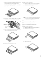
7.
Place the brackets with the fixed HDDs into the unit and
fix them using the four screws removed in step 3.
• Do not use an electric screwdriver to fix them.
Recommended tightening torque = 0.784 N · m
{8 kgf · cm}
11. Attach the front cover as it was.
11-1 Align the left edges of both the front cover and the
unit, and then push the front cover onto the unit.
11-2 Slide the front cover to the right.
15 - 2
8.
Connect the connector with gray cable to the upper
HDD and the connector with red cable to the lower.
Note: The front cover may be attached and detached
as necessary in the next step of Setup Procedures.
Be careful not to damage the harness.
12. Mount the unit referring to Mounting in a Rack.
13. Connect the unit referring to Connections.
Connector with
red cable
Connector with
gray cable
9.
14. Set up the unit referring to Setup Procedures.
15. Attach the front cover as it was.
15-1 Align the left edges of both the front cover and the
unit, and then push the front cover onto the unit.
15-2 Slide the front cover to the right.
Attach the metal plate removed in step 2 with the six
screws (marked with ∆) previously removed.
15 - 2
15-3 Tighten the two screws.
10. Connect the detached harness as it was.
15 - 3
11
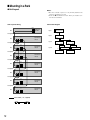
■ Mounting in a Rack
● Unit Layout
Notes:
• Be sure to make a space of 1 U (44 mm) between the
units for ventilation in a rack.
• Refer to “● Unit Number Check” when you need to confirm the unit numbers.
Connection Diagram
Unit Layout & Wiring
COPY1
Digital Disk
Recorder
2U
Layer1
EXT STORAGE
Digital Disk Recorder
EXT STORAGE
1U Space
IN
IN
OUT
2 1
2U
Layer2
WJ-HDE300
Unit #1
OUT2
OUT
2 1
2U
WJ-HDE300
Unit #2
IN
WJ-HDE300 #2
OUT2
IN
OUT1
IN
Layer3
1U Space
WJ-HDE300 #1
OUT1
2U
OUT
2 1
WJ-HDE300
Unit #3
1U Space
IN
2U
OUT
2 1
WJ-HDE300
Unit #4
1U Space
IN
OUT
2 1
2U
WJ-HDE300
Unit #5
1U Space
IN
2U
OUT
2 1
WJ-HDE300
Unit #6
1U Space
IN
2U
OUT
2 1
Serial cable (1 m, supplied)
12
WJ-HDE300
Unit #7
OUT1
IN
WJ-HDE300 #5
Layer4
WJ-HDE300 #4
IN
OUT2
IN
IN
1U Space
WJ-HDE300 #3
WJ-HDE300 #7
IN
WJ-HDE300 #6
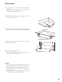
● How to Mount
1.
Turn off the power of the unit and detach the plug from
the outlet.
When not turning off the power, open the front cover
and turn off the HDD POWER switch.
2.
Remove the six rubber feet by removing the six screws
from the bottom of the unit
Remove 6 screws
3.
Fix the Rack Mounting Brackets (supplied) on both
sides of the unit with the four screws (M4X10, supplied).
M4X10 (Supplied)
Rack Mounting Bracket (Supplied)
4.
Install the unit in the rack securing it with four screws
(M5x12, not supplied).
5.
Turn on the power of the unit.
When the HDD POWER switch is turned off, turn it on
and attach the front cover as it was.
M5X12 (Not supplied)
Cautions:
• Make a space of 1U (44 mm) between the units for ventilation, and install them in the rack as low as possible.
• Keep the temperature in a rack below 45 °C (113 °F).
• Install a fan in the rack when the ambient temperature is
above 30 °C (86 °F).
• Do not block the ventilation openings or slots on the
cover to prevent the unit from overheating.
13
■ Connections
You can connect up to seven extension units with the digital
disk recorder (the WJ-HD316A/WJ-HD309A series) as
shown below using the supplied serial cables.
Important
• Never use extension cables (locally procured). Be sure
to use the supplied serial cables for connection.
• Physical connections determine the unit number in a
system for each unit. Connect units with the recorder in
numeric order as shown in the figure. For example, connect the sixth and seventh units to the third unit when
five units have been already installed.
• Do not change connections after the system has run.
Otherwise, the recorder will no longer recognize the
extension units as before. You can change connections
only when you can discard all existing data stored in
the units.
• If turning off the power of a unit, none of the connected
following units will work because of interrupted data
transmission.
Note: When the system is connected in a different way from
the figure, a unit number check can be performed on
the HDD SAFETY MODE of the digital disk recorder.
Refer to Setup Procedures.
● Procedures
1. Connect the EXT STORAGE port of the recorder and
the IN port of extension unit #1 using the supplied serial
cable.
2. Connect the OUT port of unit #1 and the IN port of unit
#2 using the supplied serial cable.
3. Repeat connections in the same way for the remaining
units.
4. Confirm the cable layout after connections.
5. Secure the cables using the clamp (supplied) and fix it
to the rear of the units.
How to fix the cable clamp
Cable Clamp
COPY
10/100
BASE-T
2
EXIT
STORAG
E
1
2
1
Fixing screw
Remove this screw from
the unit and fix the cables
with the cable clamp
Digital Disk Recorder
4
1
1
SIGNAL GND
MODE
SERIAL
3
AUDIO IN
How to fix the cables
CASCAKE
OUT
2
AUDIO OUT
16
15
14
16
15
14
2
MONITOR OUT CASCADE IN
13
12
COPY
ALARM
POWER
MONITOR (VGA)
11
10
9
ALARM/CONTOROL
8
7
6
PS·DATA
5
6
5
RS-485(CAMERA)
10/100BASE-T EXIT STORAGE
4
3
2
1
IN
AC IN
OUT
13
12
11
10
9
CAMERA
8
7
4
3
2
1
EXT STORAGE
Cable clamp
EXT
IN
IN
OUT
2
WJ-HDE300 #1
1
Screw for the
cable clamp
SIGNAL GND
POWER
EXT
IN
OUT
2
OUT2
IN
AC IN
1
OUT1
IN
WJ-HDE300 #2
WJ-HDE300 #3
SIGNAL GND
SIGNAL GND
POWER
POWER
EXT
EXT
IN
OUT2
IN
WJ-HDE300 #5
IN
IN
OUT
1
AC IN
WJ-HDE300 #7
SIGNAL GND
SIGNAL GND
POWER
POWER
EXT
2
IN
WJ-HDE300 #6
POWER
POWER
14
OUT1
SIGNAL GND
EXT
AC IN
1
OUT2
OUT1
SIGNAL GND
IN
OUT
2
AC IN
1
IN
WJ-HDE300 #4
IN
OUT
2
EXT
EXT
OUT
2
1
AC IN
IN
IN
OUT
2
1
AC IN
OUT
2
1
AC IN
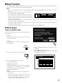
■ Setup Procedures
The following pages describe procedures on how to set up or change the disk mode, how to recover data in RAID5, or
how to check the unit number using the HDD SAFETY MODE.
Notes:
• Refer to the operating instructions of the digital disk recorder WJ-HD316A/WJ-HD309A series for setup menu operations.
• The MODE switches of all units in a system should be set
to the same position, SINGLE or RAID5.
HDD 2
HDD 4
• The HDDs should be installed in the proper positions in the
HDD 1
HDD 3
order as shown in the figure. Do not skip or reverse the
order of the HDD positions. Otherwise, the recorder will not
recognize the extension unit.
• Do not change HDD positions of the extension unit after once the system has been operated. Otherwise, it will be
impossible to read the recorded data.
• The power-on order should be the extension units first and then the recorder. The power-off order should be the
recorder first and then the units.
• At least, three hard disk drives per extension unit are needed to run it in the RAID5 mode.
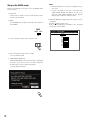
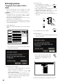
● Basic Setups
Setup to the SINGLE mode
Perform the following to set up the unit to the SINGLE mode
for the first time.
1 Power OFF
Confirm that the power of the recorder and the extension units are turned off.
2 SINGLE
Set the MODE switch inside the front lid of the extension
unit to SINGLE.
SET
MODE
SINGLE RAID5
3 Turn on the power switch of the extension units.
6 HDD DISK MENU will appear when the system check is
completed.
Perform formatting on the menu.
Refer to "■ Formatting the Hard Disk" of the operating
instructions of the recorder.
HDD DISK MENU
WJ-HD300A TOP MENU
Digital Disk Recorder
POWER
FORMAT
MAIN
4 Turn on the power switch of the recorder.
→ The recorder will start.
EXT1
EXT2
EXT3
EXT4
5 HDD SAFETY MODE OFF
"HDD SAFETY MODE" menu will open after completing
the system check. Select OFF on the menu and press
the SET button on the recorder’s front panel.
→ The recorder will restart.
Notes:
• It will take about 3 or 5 minutes to complete the system check.
• If "ON" is selected on the menu of the main unit,
"HDD SAFETY MODE" will appear. If "ON" is not
selected, "HDD SAFETY MODE" will not appear.
Skip the step 5 and proceed to the step 6.
EXT5
EXT6
MIRROR ON MIRROR OFF REMOVE LINK RESTART
1
160GB
160GB
160GB
160GB
*(160GB)
ADD (160GB)
160GB
EXT7 LOST
2
160GB
160GB
160GB
160GB
*(ERROR)
ADD (ERROR)
160GB
-
3
160GB
160GB
160GB
160GB
160GB
160GB
-
EXIT
4
160GB
160GB
160GB
160GB
160GB
160GB
-
Information of recording areas : [SETUP/ESC] OK : [SET]
15
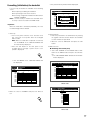
Setup to the RAID5 mode
Perform the following to set up the unit to the RAID5 mode
for the first time.
1 Power OFF
Confirm that the power of the recorder and the extension units are turned off.
2 RAID5
Set the MODE switch inside the front lid of the extension
unit to RAID5.
Notes:
• It will take about 3 or 5 minutes to complete the system check.
• If "ON" is selected on the menu of the main unit,
"HDD SAFETY MODE" will appear. If "ON" is not
selected, "HDD SAFETY MODE" will not appear.
Skip the step 5 and proceed to the step 6.
6 HDD DISK MENU will appear when the system check is
completed.
Perform formatting on the menu.
Refer to "■ Formatting the Hard Disk" of the operating
instructions of the recorder.
MODE
SINGLE RAID5
HDD DISK MENU
WJ-HD300A TOP MENU THE CANDIDATE FOR A FORMAT
Digital Disk Recorder
ALL UNIT
ONE UNIT
MAIN EXT1 480GB
3 Turn on the power switch of the extension units.
EXT2 480GB
EXT3 480GB
EXT4 *(480GB)
EXT5 ADD (480GB)
EXT6 480GB
EXT7 LOST
POWER
4 Turn on the power switch of the recorder.
→ The recorder will start.
5 HDD SAFETY MODE OFF
"HDD SAFETY MODE" menu will open after completing
the system check. Select OFF on the menu and press
the SET button on the recorder’s front panel.
→ The recorder will restart.
SET
16
RETURN: [SETUP/ESC] OK : [SET]
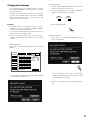
Formatting (Initialization) the hard disk
It is necessary to initialize the hard disk in the following
cases.
When replacing or adding the hard disk
When operating the unit for the first time
When having changed the hard disk mode between
SINGLE and RAID5
Note: It is unnecessary to initialize the hard disk when
recovery is to be executed in the RAID5 mode.
→ The password entry window will be displayed.
HDD DISK MENU
WJ-HD300A TOP MENU
Digital Disk Recorder
FORMAT
MAIN
EXT1
EXT2
EXT3
EXT4
EXT5
Important:
When the hard disk is formatted (initialized), all of the
recorded images will be deleted.
1 Power up
• Turn on the power switches of the extension units
first. Then turn on the power switch of the digital
disk recorder.
Note: When the hard disk is replaced or removed,
the "TOP MENU" of the "HDD DISK MENU" will
be automatically displayed.
• Press the SET button on the front panel of the
recorder when a message " System check is completed" is displayed.
SET
→ The "TOP MENU" of the "HDD DISK MENU" will
be displayed.
EXT6
EXT7
MIRROR ON MIRROR OFF REMOVE LINK RESTART
1
2
3
160GB M
160GB M
Enter the password.
160GB
160GB
160GB
160GB
160GB
160GB
160GB
160GB
160GB
*(160GB)
*(ERROR)
160GB
ADD (160GB) EXECUTE
ADD (ERROR) CANCEL
160GB
160GB
160GB
160GB
LOST
-
EXIT
4
160GB
160GB
160GB
160GB
160GB
160GB
-
Information of recording areas : [SETUP/ESC] OK : [SET]
3 Password entry
• Enter the password for an administrator by rotating
the jog dial. Camera selection buttons are available
to enter numbers for password.
• Move the cursor to "EXECUTE" and press the SET
button.
4 Mode selection
● Initializing all hard disk (unit)
• Select "ALL FORMAT" for the SINGLE mode or "ALL
UNIT" for the RAID5 mode and press the SET button.
→ The "RECORDING AREA SETUP OF ALL DISKS"
will be displayed.
HDD DISK MENU
WJ-HD300A TOP MENU THE CANDIDATE FOR A FORMAT
Digital Disk Recorder
ALL FORMAT SELECTED DISK MIRROR FORMAT
1
HDD DISK MENU
WJ-HD300A TOP MENU
Digital Disk Recorder
EXT1
FORMAT
MIRROR ON MIRROR OFF REMOVE LINK RESTART
1
2
160GB
160GB
160GB
160GB
160GB
160GB
160GB
*(160GB)
*(ERROR)
ADD (160GB) ADD (ERROR)
160GB
160GB
LOST
-
MAIN 160GB
EXT1
EXT2
EXT3
EXT4
EXT5
EXT6
EXT7
2
160GB
160GB
160GB
160GB
160GB
160GB
160GB
*(160GB)
*(ERROR)
ADD (160GB) ADD (ERROR)
160GB
160GB
LOST
-
3
4
MAIN 160GB
3
160GB
160GB
160GB
160GB
160GB
160GB
-
EXIT
EXT2
4
160GB
160GB
160GB
160GB
160GB
160GB
-
EXT3
EXT4
EXT5
EXT6
EXT7
160GB
160GB
160GB
160GB
160GB
160GB
-
160GB
160GB
160GB
160GB
160GB
160GB
-
RETURN: [SETUP/ESC] OK : [SET]
SINGLE mode
Information of recording areas : [SETUP/ESC] OK : [SET]
HDD DISK MENU
WJ-HD300A TOP MENU THE CANDIDATE FOR A FORMAT
Digital Disk Recorder
2 Move the cursor to "FORMAT" and press the SET button.
ALL UNIT
ONE UNIT
MAIN EXT1 480GB
EXT2 480GB
SET
EXT3 480GB
EXT4 *(480GB)
EXT5 ADD (480GB)
EXT6 480GB
EXT7 LOST
RETURN: [SETUP/ESC] OK : [SET]
RAID5 mode
17
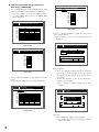
● Initializing selected hard disk (the selected unit
when using the RAID5 mode)
• Select "SELECTED DISK" for the SINGLE mode or "ONE
UNIT" for the RAID5 mode and press the SET button.
→ The "DISK SELECT" menu for the SINGLE mode or
the "UNIT SELECTION" menu for the RAID5 mode
will be displayed.
Digital Disk Recorder
WJ-HD300A
HDD DISK MENU
UNIT SELECTION THE SETTING METHOD
Auto Setup
All Copy Area All Pre REC Area Detailed Setup
MAIN EXT1 480GB
EXT2 480GB
EXT3 480GB
EXT4 *(480GB)
EXT5 ADD (480GB)
EXT6 480GB
Digital Disk Recorder
WJ-HD300A
HDD DISK MENU
THE CANDIDATE FOR A FORMAT
EXT7 LOST
DISK SELECT
RETURN: [SETUP/ESC] OK : [SET]
Select HDD to be formatted,and press [SET]key.
1
2
160GB
160GB
160GB
160GB
160GB
160GB
*(160GB)
*(ERROR)
ADD (160GB) ADD (ERROR)
160GB
160GB
LOST
MAIN 160GB
EXT1 160GB
EXT2
EXT3
EXT4
EXT5
EXT6
EXT7
3
4
160GB
160GB
160GB
160GB
160GB
160GB
-
160GB
160GB
160GB
160GB
160GB
160GB
-
RAID5 mode
• Select a setting method by moving the cursor and
press the SET button.
→ The confirmation menu of the recording area will be
displayed.
RETURN: [SETUP/ESC] OK : [SET]
Digital Disk Recorder HDD DISK MENU
WJ-HD300A THE CANDIDATE FOR A FORMAT RECORDING AREA SETUP OF ALL DISK
SINGLE mode
Digital Disk Recorder
WJ-HD300A
HDD DISK MENU
THE CANDIDATE FOR A FORMAT
UNIT SELECTION
NORMAL
EVENT
COPY
FREE
90GB
1800GB
450GB
450GB
Select HDD to be formatted,and press [SET] key.
MAIN HDD Total capacity : 2790GB
EXT1 480GB
EXT2 480GB
EXT3 480GB
EXT4 *(480GB)
RETURN: [SETUP/ESC] OK : [SET]
EXT5 ADD (480GB)
EXT6 480GB
EXT7 LOST
RETURN: [SETUP/ESC] OK : [SET]
RAID5 mode
• Select the desired hard disk (or unit) and press the SET
button.
→ The "SETTING METHOD" menu will be displayed.
Digital Disk Recorder
WJ-HD300A
HDD DISK MENU
DISK SELECT THE SETTING METHOD
Auto Setup
MAIN
EXT1
EXT2
EXT3
EXT4
EXT5
EXT6
5 Area selection
• Select the desired recording area to be initialized
by moving the cursor and specify the capacity by
rotating the jog dial. Repeat this to assign two or
more areas.
• Confirm the capacities of the set recording areas
and press the SET button.
→ The confirmation dialog window will be displayed.
All Copy Area All Pre REC Area Detailed Setup
1
160GB
160GB
160GB
160GB
*(160GB)
ADD (160GB)
160GB
EXT7 LOST
2
160GB
160GB
160GB
160GB
*(ERROR)
ADD (ERROR)
160GB
-
3
160GB
160GB
160GB
160GB
160GB
160GB
-
4
160GB
160GB
160GB
160GB
160GB
160GB
-
Digital Disk Recorder HDD DISK MENU
WJ-HD300A THE CANDIDATE FOR A FORMAT RECORDING AREA SETUP OF ALL DISK
NORMAL
90GB
EVENT
COPY
Starting format of all HDDs,
and
all of data in450GB
HDDs
1800GB
are going to be erased.
EXECUTE
FREE
450GB
CANCEL
HDD Total capacity : 2790GB
RETURN: [SETUP/ESC] OK : [SET]
RETURN: [SETUP/ESC] OK : [SET]
SINGLE mode
6 Execute
• Select "EXECUTE" and press the SET button.
→ The window will return to the TOP after completing the formatting.
18
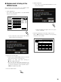
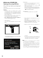
● Replacement & Setup in the
SINGLE mode
4 SAFETY MODE OFF
• Select OFF on the HDD SAFETY MODE menu and
press the SET button.
When the drive has become faulty in the SINGLE mode,
perform replacement and setup as shown below.
1 SAFETY MODE ON
Select ON for HDD Safety Mode on the SETUP MENU
and press the SET button.
SETUP MENU
Advanced
System
Recording
Event
Schedule
Switcher
Display
Comm
Maintenance
1
REC Rate
Disk Info
Version Info
MAIN 160GB
EXT1
Disk End Mode
EXT2
Disk Capacity
EXT3
Date Delete
EXT4
EXT5
Event Log
EXT6
Error Log
EXT7
Access Log
Quick Menu
15000h
160GB
15000h
160GB
15000h
160GB
15000h
160GB
15000h
160GB
15000h
160GB
15000h
160GB
15000h
2
3
4
160GB
15000h
160GB
15000h
160GB
15000h
160GB
15000h
160GB
15000h
160GB
15000h
160GB
15000h
160GB
15000h
160GB
15000h
160GB
15000h
160GB
15000h
160GB
15000h
160GB
15000h
160GB
15000h
160GB
15000h
160GB
15000h
160GB
15000h
160GB
15000h
160GB
15000h
160GB
15000h
160GB
15000h
160GB
15000h
LIVE
Remaining
Normal REC Area
Event REC Area
Copy Area
Copy 1(Rear)
Copy 2(Front)
■ Warning for Disk Life Time
■ HDD Safety Mode
1800GB
1200GB
1000GB
1000GB
1000GB
SET
30000h
ON
→ HDD DISK MENU will appear when the system
check is completed.
SET
→ The recorder will restart and the HDD SAFETY
MODE window will be displayed.
5 Perform formatting for the new drive using the menu.
Refer to “■ Formatting the Hard Disk” of the operating
instructions of the recorder.
HDD DISK MENU
WJ-HD300A TOP MENU
Digital Disk Recorder
FORMAT
MAIN
EXT1
EXT2
EXT3
EXT4
EXT5
EXT6
MIRROR ON MIRROR OFF REMOVE LINK RESTART
1
160GB
160GB
160GB
160GB
*(160GB)
ADD (160GB)
160GB
EXT7 LOST
2
160GB
160GB
160GB
160GB
*(ERROR)
ADD (ERROR)
160GB
-
3
160GB
160GB
160GB
160GB
160GB
160GB
-
EXIT
4
160GB
160GB
160GB
160GB
160GB
160GB
-
Information of recording areas : [SETUP/ESC] OK : [SET]
2 Replacement of faulty HDD
• Confirm that the HDD POWER indicator on the front
panel of the extension unit has gone out.
• Replace the faulty hard disk referring to
■ Replacing/Mounting HDD.
• Go to the next step below after finishing the connection of the front cover harness with the unit while
the switches and buttons remain operable (step 11
of ■ Replacing/Mounting HDD).
3 Press the RESET button.
RESET
19
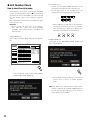
● Changing Setups
Changing the total number of HDD in
RAID5
Do the following when the total number of the hard
disks in the extension unit is increased (3 to 4) or
reduced (4 to 3) after the system has been operated.
Important:
• The MODE switches of all extension units in a system
should be set to the same position, SINGLE or RAID5.
Otherwise, the system will malfunction.
• At least three hard disk drives per extension unit are
needed to run it in the RAID5 mode.
• When the total number of the hard disks in an extension
unit is increased or reduced, all data previously stored
in the unit will be erased.
3 Initializing the unit
MODE
1 Set the MODE switch to SINGLE.
SINGLE RAID5
2 While holding down the RECOVER but1
ton, press the RESET button.
3 While holding down the RECOVER button, release
the RESET button about 1 second later.
4 Release the RECOVER button after the HDD
POWER indicator turns on (5 seconds later).
5 Repeat the above steps when initializing two or
more units.
ERROR
HDD
POWER
RESET
MODE
SINGLE RAID5
HDD
POWER
OFF
OPERATE
Press Release
ON
RECOVER
HDD
POWER
1 SAFETY MODE ON
Select ON for "HDD Safety Mode" and close the SETUP
MENU.
3
2
HDD POWER
2
4
Hold
Release
MODE
SINGLE RAID5
SETUP MENU
Advanced
System
Recording
Event
Schedule
Switcher
Display
Comm
Maintenance
1
REC Rate
Disk Info
Version Info
MAIN 160GB
EXT1
Disk End Mode
EXT2
Disk Capacity
EXT3
Date Delete
EXT4
EXT5
Event Log
EXT6
Error Log
EXT7
Access Log
Quick Menu
15000h
160GB
15000h
160GB
15000h
160GB
15000h
160GB
15000h
160GB
15000h
160GB
15000h
160GB
15000h
2
3
4
160GB
15000h
160GB
15000h
160GB
15000h
160GB
15000h
160GB
15000h
160GB
15000h
160GB
15000h
160GB
15000h
160GB
15000h
160GB
15000h
160GB
15000h
160GB
15000h
160GB
15000h
160GB
15000h
160GB
15000h
160GB
15000h
160GB
15000h
160GB
15000h
160GB
15000h
160GB
15000h
160GB
15000h
160GB
15000h
■ Warning for Disk Life Time
■ HDD Safety Mode
LIVE
Remaining
Normal REC Area
Event REC Area
Copy Area
COPY 1 (Rear)
COPY 2 (Front)
1800GB
1200GB
1000GB
1000GB
1000GB
4 Set the MODE switch back to RAID5.
5 SAFETY MODE OFF
• Select OFF on the HDD SAFETY MODE window and
press the SET button.
30000h
OFF
→ The recorder will restart and the HDD SAFETY MODE
window will be displayed.
→ The recorder will restart and the HDD
DISK MENU will be displayed after the
system check is completed (3 - 5 minutes later).
SET
HDD DISK MENU
WJ-HD300A TOP MENU THE CANDIDATE FOR A FORMAT
Digital Disk Recorder
ALL UNIT
ONE UNIT
MAIN -
2 Install/uninstall the hard disk
• Confirm that the HDD POWER indicator on the front
panel of the extension unit went out.
• Install or uninstall the hard disk referring to ■
Replacing/Mounting HDD.
• Go to the next step below after finishing the connection of the front cover harness with the unit while
the switches and buttons remain operable (step 11
of ■ Replacing/Mounting HDD).
20
EXT1 480GB
EXT2 480GB
EXT3 480GB
EXT4 *(480GB)
EXT5 ADD (480GB)
EXT6 480GB
EXT7 LOST
RETURN: [SETUP/ESC] OK : [SET]
• Perform the formatting of the changed extension unit.
Changing hard disk mode
Do the following when the hard disk mode is changed
from SINGLE to RAID5 or vice versa after the system
has been operated.
Skip this section and perform settings in the same way
as "Setup to the SINGLE mode" or "Setup to the RAID5
mode" when the power switches of the recorder and
extension units are accessible.
Important:
• The MODE switches of all extension units in a system
should be set to the same position, SINGLE or RAID5.
Otherwise, the system will malfunction.
• At least, three hard disk drives per extension unit are
needed to run it in the RAID5 mode.
• When the hard disk mode of the extension unit is
changed, all data previously stored in the unit will be
erased.
2 Change the mode
• Confirm that the HDD POWER indicator on the front
panel of the extension unit went out.
• Change the MODE switch on the unit to SINGLE or
RAID5. The default position is SINGLE.
MODE
MODE
SINGLE RAID5
SINGLE RAID5
• Press the RESET button.
RESET
3 SAFETY MODE OFF
• Select OFF on the HDD SAFETY MODE menu and
press the SET button.
1 SAFETY MODE ON
Select ON for "HDD Safety Mode" and close the SETUP
MENU.
SETUP MENU
Advanced
System
Recording
Event
Schedule
Switcher
Display
Comm
Maintenance
1
REC Rate
Disk Info
Version Info
MAIN 160GB
15000h
EXT1 160GB
Disk End Mode
EXT2
Disk Capacity
EXT3
Date Delete
EXT4
EXT5
Event Log
EXT6
Error Log
EXT7
Access Log
Quick Menu
15000h
160GB
15000h
160GB
15000h
160GB
15000h
160GB
15000h
160GB
15000h
160GB
15000h
2
3
4
160GB
15000h
160GB
15000h
160GB
15000h
160GB
15000h
160GB
15000h
160GB
15000h
160GB
15000h
160GB
15000h
160GB
15000h
160GB
15000h
160GB
15000h
160GB
15000h
160GB
15000h
160GB
15000h
160GB
15000h
160GB
15000h
160GB
15000h
160GB
15000h
160GB
15000h
160GB
15000h
160GB
15000h
160GB
15000h
■ Warning for Disk Life Time
■ HDD Safety Mode
LIVE
Remaining
Normal REC Area
Event REC Area
Copy Area
Copy 1(Rear)
Copy 2(Front)
1800GB
1200GB
1000GB
1000GB
1000GB
SET
30000h
ON
→ The recorder will restart and the HDD SAFETY MODE
window will be displayed.
→ The recorder will restart and the HDD DISK
MENU will be displayed after the system check
is completed (3 - 5 minutes).
• Perform the formatting of the changed extension
unit.
21
● Recovery of RAID5 Disk
Replacing and recovering RAID5 disk
When an HDD access indicator on the front panel of the
extension unit is lit red, it indicates that the hard disk drive
malfunctions.
Do the following to replace and recover the faulty hard disk.
Important:
• Immediately replace the hard disk when an HDD
access indicator is lit red. If one indicator is lit red and
the other blinks red, or the second hard disk fails during
the recovery process, it is impossible to recover the
data as a RAID5 system.
• When the ERROR indicator is lit red, it is a system error.
Consult your dealer. Refer to Troubleshooting.
• Refer to ■ Replacing/Mounting HDD for details on
types, mounting positions, and number of hard disk drives that should be installed in the unit.
1 SAFETY MODE ON
Select ON for "HDD Safety Mode" and close the SETUP
MENU.
2 Replacement
• Confirm that the HDD POWER indicator on the front
panel of the extension unit went out.
• Replace the faulty hard disk referring to ■
Replacing/Mounting HDD.
• Go to the next step below after finishing the connection of the front cover harness with the unit while
the switches and buttons remain operable (step 11
of ■ Replacing/Mounting HDD).
3 Data Recovery
1 Confirm that the MODE switch is set to RAID5.
MODE
SINGLE RAID5
1
2 While holding down the RECOVER button, press the
RESET button.
3 While holding down the RECOVER button, release
the RESET button about 1 second later.
4 Release the RECOVER button after the HDD
POWER indicator turns on (5 seconds later).
5 Repeat the above steps when initializing two or
HDD DISK MENU
WJ-HD300A TOP MENU THE CANDIDATE FOR A FORMAT
Digital Disk Recorder
ALL UNIT
ONE UNIT
HDD
POWER
ERROR
RESET
MAIN MODE
EXT1 480GB
SINGLE RAID5
EXT2 480GB
HDD
POWER
EXT3 480GB
OFF
EXT4 *(480GB)
EXT5 ADD (480GB)
EXT6 480GB
HDD POWER
OPERATE
HDD
POWER
ON
3
2
Press Release
RECOVER
2
4
EXT7 LOST
RETURN: [SETUP/ESC] OK : [SET]
→ The recorder will restart and the HDD SAFETY MODE
window will be displayed.
Hold
Release
more units.
→ The HDD access indicator of the drive will blink red
and orange alternately during the recovery process
and will go out when the process is completed
Notes:
• For reference, it will take about 12 hours to complete
the recovery process for 160 GB data.
• Do not operate any switch or button of the extension
unit while the HDD indicator of the drive in the recovery
process blinks red and orange alternately. Otherwise,
the process will fail.
• The recorder can be operated during the data recovery
process, though the recovery time will be lengthened.
22
4 HDD SAFETY MODE OFF
• Select OFF on the HDD SAFETY MODE window and
press the SET button.
• Select EXIT and press the SET button to close the
menu.
HDD DISK MENU
WJ-HD300A TOP MENU THE CANDIDATE FOR A FORMAT
Digital Disk Recorder
ALL FORMAT SELECTED DISK MIRROR FORMAT
1
2
160GB
160GB
160GB
160GB
160GB
160GB
160GB
*(160GB)
*(ERROR)
ADD (160GB) ADD (ERROR)
160GB
160GB
LOST
-
3
4
MAIN 160GB
EXT1
EXT2
EXT3
EXT4
EXT5
EXT6
EXT7
160GB
160GB
160GB
160GB
160GB
160GB
-
160GB
160GB
160GB
160GB
160GB
160GB
-
RETURN: [SETUP/ESC] OK : [SET]
SET
→ The recorder will restart and enter the system
check mode. After 3 or 5 minutes, the system
check complete window will be displayed.
SET
• Press the SET button to display the HDD DISK
MENU.
23
Setting/Changing hard disk mode after
resetting error
→ The recorder will restart and the HDD SAFETY
MODE window will be displayed.
It is impossible to change or set up the hard disk mode
when the ERROR indicator and one of HDD access
indicators is lit red or is blinking. To set or change the
mode, repair the system so the indicators go out.
Refer to Troubleshooting of this manual and the operating instructions of the digital disk recorder for details.
Important:
• When an HDD indicator is lit or blinking red, the
HDD is faulty and should be replaced performing
the following steps.
• When less than three hard disks are mounted or the
mounted positions are wrong in RAID5, the HDD
indicators will blink red and be lit red. Add hard
disk(s) or correct the positions and then set up the
extension unit again.
• When the ERROR indicator is lit red and all HDD
access indicators are lit red and orange, it is a system error. Consult your dealer.
1 SAFETY MODE ON
Select ON for HDD Safety Mode on the SETUP MENU
and press the SET button.
SETUP MENU
Advanced
System
Recording
Event
Schedule
Switcher
Display
Comm
Maintenance
1
REC Rate
Disk Info
Version Info
MAIN 160GB
15000h
EXT1 160GB
15000h
Disk End Mode
EXT2 160GB
Disk Capacity
EXT3
Date Delete
EXT4
EXT5
Event Log
EXT6
Error Log
EXT7
Access Log
Quick Menu
15000h
160GB
15000h
160GB
15000h
160GB
15000h
160GB
15000h
160GB
15000h
2
160GB
15000h
160GB
15000h
160GB
15000h
160GB
15000h
160GB
15000h
160GB
15000h
160GB
15000h
160GB
15000h
3
160GB
15000h
160GB
15000h
160GB
15000h
160GB
15000h
160GB
15000h
160GB
15000h
160GB
15000h
■ Warning for Disk Life Time
■ HDD Safety Mode
4
160GB
15000h
160GB
15000h
160GB
15000h
160GB
15000h
160GB
15000h
160GB
15000h
160GB
15000h
2 Replacement of faulty HDD
• Confirm that the HDD POWER indicator on the front
panel of the extension unit has gone out.
• Replace the faulty hard disk referring to
■ Replacing/Mounting HDD.
• Go to the next step below after finishing the connection of the front cover harness with the unit while
the switches and buttons remain operable (step 11
of ■ Replacing/Mounting HDD).
3 Initialization
1 Set the MODE switch to SINGLE.
LIVE
MODE
Remaining
Normal REC Area
Event REC Area
Copy Area
Copy 1(Rear)
Copy 2(Front)
SINGLE RAID5
1800GB
1200GB
1000GB
1000GB
1000GB
30000h
ON
1
2 While holding down the RECOVER button, press the
RESET button.
3 While holding down the RECOVER button, release
the RESET button about 1 second later.
4 Release the RECOVER button after the HDD
POWER indicator turns on.
SET
ERROR
HDD
POWER
RESET
MODE
SINGLE RAID5
HDD
POWER
HDD POWER
OFF
OPERATE
ON
RECOVER
2
HDD
POWER
24
3
2
Press Release
Hold
4
Release
→ After that, the HDD DISK MENU respective to the
selected mode (SINGLE or RAID5) will be displayed automatically.
4 MODE switch setting
Set the MODE switch to SINGLE or RAID5.
MODE
MODE
SINGLE RAID5
SINGLE RAID5
HDD DISK MENU
WJ-HD300A TOP MENU THE CANDIDATE FOR A FORMAT
Digital Disk Recorder
ALL UNIT
ONE UNIT
MAIN EXT1 480GB
5 SAFETY MODE OFF
• Select OFF and press the SET button.
EXT2 480GB
EXT3 480GB
EXT4 *(480GB)
EXT5 ADD (480GB)
EXT6 480GB
EXT7 LOST
RETURN: [SETUP/ESC] OK : [SET]
• Perform formatting referring to ■ Formatting
(Initialization) the Hard Disk of the operating instructions of the recorder.
SET
→ The recorder will restart. After 3 or 5 minutes,
the system check complete window will be displayed.
25
● Unit Number Check
How to check the unit number
Each extension unit is given a unit number depending
on the connected position. Refer to ■ Connections of
this manual for the recommended connection form and
the unit numbers given to the respective extension
units.
Do the following to check which unit numbers are given
to the extension units.
Important
• Do not change the connections of the extension
units after the system has been operated.
Otherwise, the recorder will fail to recognize the
extension units.
2 Unit number check
• Confirm that the HDD POWER indicators on the
front panel of the extension units have gone out.
• On the front panel of the recorder, press the
Camera Selection buttons from [1] to [7] in order.
1
SETUP MENU
Advanced
System
Recording
Event
Schedule
Switcher
Display
Comm
Maintenance
1
REC Rate
Disk Info
Version Info
MAIN 160GB
15000h
EXT1 160GB
Disk End Mode
EXT2
Disk Capacity
EXT3
Date Delete
EXT4
EXT5
Event Log
EXT6
Error Log
EXT7
Access Log
Quick Menu
15000h
160GB
15000h
160GB
15000h
160GB
15000h
160GB
15000h
160GB
15000h
160GB
15000h
2
3
4
160GB
15000h
160GB
15000h
160GB
15000h
160GB
15000h
160GB
15000h
160GB
15000h
160GB
15000h
160GB
15000h
160GB
15000h
160GB
15000h
160GB
15000h
160GB
15000h
160GB
15000h
160GB
15000h
160GB
15000h
160GB
15000h
160GB
15000h
160GB
15000h
160GB
15000h
160GB
15000h
160GB
15000h
160GB
15000h
■ Warning for Disk Life Time
■ HDD Safety Mode
3
4
SEQ
5
6
7
→ All the HDD access indicators of the respective
unit will be lit red for 5 seconds. For example,
when the button [1] is pressed, the HDD access
indicators on the extension unit #1 will be lit.
HDD 1
1 SAFETY MODE ON
Select ON for HD Safety Mode and press the SET button.
2
HDD 2
HDD 3
HDD 4
3 SAFETY MODE OFF
Select OFF on the HDD SAFETY MODE window and
press the SET button.
LIVE
Remaining
Normal REC Area
Event REC Area
Copy Area
Copy 1(Rear)
Copy 2(Front)
1800GB
1200GB
1000GB
1000GB
1000GB
30000h
ON
SET
SET
→ The recorder will restart and the HDD SAFETY
MODE window will be displayed.
→ The recorder will restart. After 3 or 5 minutes of
system check, it will run in normal operation
mode.
Note: The HDD access indicator that is lit red or blinking due to failure of the hard disk in RAID5 will keep
its state while the other indicators of the unit are lit
red to display the unit number.
26
■ Troubleshooting
Symptom
Cause
What to do
No power is supplied.
Insufficient power cord connection
POWER switch or HDD POWER switch is
turned off.
Securely connect the power cord.
Turn on the POWER switch and HDD
POWER switch.
ERROR indicator lights orange.
Thermal error has stopped the
unit.
Cooling fan(s) may be faulty.
Ambient temperature exceeds the operable
range.
Ventilation may be blocked.
Repair cooling fan(s).
Arrange the ambient temperature so that
it lies within the acceptable range.
Remove obstacles blocking the openings or slots. See below for cleaning.
ERROR indicator lights red.
System fault
Repair is required.
Extension unit or added HDD is
not recognized.
Connection cables other than supplied may
have been used.
Insufficient connector junction
Powering up the recorder and units in opposite
order
Use the supplied cable.
The recorder and units are connected to different AC mains
HDD installation position is wrong.
MODE switch setting
Firmly join the cables and connectors.
The order should be "the extension units
first, then the recorder" or at the same
time.
Keep the above order for powering up,
or rearrange the AC mains connection to
the same source.
Install HDDs in order from the position
#1, #2, #3, and #4. Never skip or reverse
the order.
Set the MODE switch appropriately.
HDD access indicator alternately
blinks orange and red or blinks
green though no recording/playback.
In recovery process of RAID5
Automatic periodic (every 5 seconds) data
check in RAID5
Not a problem
Data recovery fails after replacing the HDDs in the RAID 5
mode.
The HDD to be recovered may be faulty.
Repair the faulty HDD.
Size of the new HDD may be smaller than
before although nominally the same.
Install an HDD larger than before or the
same size.
The HDDs have not been replaced correctly.
Never skip or reverse the position.
The cables are not connected correctly to the
HDDs.
Check that the cables are connected to
the HDDs correctly and firmly.
HDD access indicators light and
blink red.
Disk drive is faulty in RAID5 mode.
Repair the faulty HDD and implement
The steady light means it is the first faulty drive, the recovery process.
the blinking light means it is one of the later
ones.
HDD access indicators light red
and orange.
System fault
Red and orange lighting of these four bits displays error status as shown below.
8: Red
9: Orange
9 8 8 8: Hardware error
8 9 8 8: Hardware error
9 9 8 8: Hardware error
8 8 9 8: Hardware error
9 8 9 8: Hardware error
8 9 9 8: Hardware error
9 9 9 8: Hardware error
8 8 8 9: Hardware error
8 9 8 9: Hardware error
9 9 8 9: Hardware error
8 8 9 9: Hardware error
8 9 9 9: Disk CRC error
Repair is required.
27
■ Specifications
Required power:
Power consumption:
Interface:
Operating temperature:
Operating humidity:
Dimensions:
Weight:
220 V AC - 240 V AC 50 Hz
85 W (including 4 HDDs when installed)
2-wire serial, 480 Mbps logical speed
+5 °C to +45 °C (41 °F to 113 °F)
Less than 85 %
420 mm (W) x 88 mm (H) x 350 mm (D), rubber feet exclusive
19-9/16" (W) x 3-7/16" (H) x 13-13/16" (D)
7.2 kg (16 lbs) (not including hard disk drives)
Weight and dimensions indicated are approximate.
Specifications are subject to change without notice.
■ Accessories
Operating instructions (this document)....................... 1 pc.
The following are for installation.
Power cord ................................................................. 1 pc.
Serial cable ................................................................. 1 pc.
Rack mounting bracket .............................................. 2 pcs.
Bracket fixing screw ................................................... 4 pcs.
28
HDD fixing screw ...................................................... 16 pcs.
Damper ..................................................................... 16 pcs.
Sleeve ....................................................................... 16 pcs.
[English]
Declaration of Conformity with the requirements of Technical Regulation on the Restriction Of the use of certain
Hazardous Substances in Electrical and Electronic Equipment (adopted by Order No.1057 of Cabinet of Ministers of
Ukraine)
The Product is in conformity with the requirements of Technical Regulation on the Restriction Of the use of certain Hazardous Substances in
electrical and electronic equipment (TR on RoHS).
The content of hazardous substance with the exemption of the applications listed in the Annex No.2 of TR on RoHS:
1. Lead (Pb) – not over 0,1wt % or 1000wt ppm;
2. Cadmium (Cd) – not over 0,01wt % or 100wt ppm;
3. Mercury (Hg) – not over 0,1wt % or 1000wt ppm;
4. Hexavalent chromium (Cr6+) – not over 0,1wt % or 1000wt ppm;
5. Polybrominated biphenyls (PBBs) – not over 0,1wt % or 1000wt ppm;
6. Polybrominated diphenyl ethers (PBDEs) – not over 0,1wt % or 1000wt ppm.
[êÛÒÒÍËÈ flÁ˚Í]
ÑÂÍ·‡ˆËfl Ó ëÓÓÚ‚ÂÚÒÚ‚ËË í·ӂ‡ÌËflÏ íÂıÌ˘ÂÒÍÓ„Ó ê„·ÏÂÌÚ‡ Ó· 鄇Ì˘ÂÌËË àÒÔÓθÁÓ‚‡ÌËfl ÌÂÍÓÚÓ˚ı ljÌ˚ı Ç¢ÂÒÚ‚ ‚
˝ÎÂÍÚ˘ÂÒÍÓÏ Ë ˝ÎÂÍÚÓÌÌÓÏ Ó·ÓÛ‰Ó‚‡ÌËË (ÛÚ‚ÂʉfiÌÌÓ„Ó èÓÒÚ‡ÌÓ‚ÎÂÌËÂÏ ‹1057 䇷ËÌÂÚ‡ åËÌËÒÚÓ‚ ì͇ËÌ˚)
àÁ‰ÂÎË ÒÓÓÚ‚ÂÚÒÚ‚ÛÂÚ Ú·ӂ‡ÌËflÏ íÂıÌ˘ÂÒÍÓ„Ó ê„·ÏÂÌÚ‡ Ó· 鄇Ì˘ÂÌËË àÒÔÓθÁÓ‚‡ÌËfl ÌÂÍÓÚÓ˚ı ljÌ˚ı Ç¢ÂÒÚ‚ ‚ ˝ÎÂÍÚ˘ÂÒÍÓÏ Ë ˝ÎÂÍÚÓÌÌÓÏ
Ó·ÓÛ‰Ó‚‡ÌËË (íê éàÇÇ).
ëÓ‰ÂʇÌË ‚‰Ì˚ı ‚¢ÂÒÚ‚ ‚ ÒÎÛ˜‡flı, Ì Ô‰ÛÒÏÓÚÂÌÌ˚ı ÑÓÔÓÎÌÂÌËÂÏ ‹2 íê éàÇÇ:
1. Ò‚Ë̈ (Pb) – Ì Ô‚˚¯‡ÂÚ 0,1 % ‚ÂÒ‡ ‚¢ÂÒÚ‚‡ ËÎË ‚ ÍÓ̈ÂÌÚ‡ˆËË ‰Ó 1000 ÏËÎÎËÓÌÌ˚ı ˜‡ÒÚÂÈ;
2. ͇‰ÏËÈ (Cd) – Ì Ô‚˚¯‡ÂÚ 0,01 % ‚ÂÒ‡ ‚¢ÂÒÚ‚‡ ËÎË ‚ ÍÓ̈ÂÌÚ‡ˆËË ‰Ó 100 ÏËÎÎËÓÌÌ˚ı ˜‡ÒÚÂÈ;
3. ÚÛÚ¸ (Hg) – Ì Ô‚˚¯‡ÂÚ 0,1 % ‚ÂÒ‡ ‚¢ÂÒÚ‚‡ ËÎË ‚ ÍÓ̈ÂÌÚ‡ˆËË ‰Ó 1000 ÏËÎÎËÓÌÌ˚ı ˜‡ÒÚÂÈ;
4. ¯ÂÒÚË‚‡ÎÂÌÚÌ˚È ıÓÏ (Cr6+) – Ì Ô‚˚¯‡ÂÚ 0,1 % ‚ÂÒ‡ ‚¢ÂÒÚ‚‡ ËÎË ‚ ÍÓ̈ÂÌÚ‡ˆËË ‰Ó 1000 ÏËÎÎËÓÌÌ˚ı ˜‡ÒÚÂÈ;
5. ÔÓÎË·ÓÏ·ËÙÂÌÓÎ˚ (PBB) – Ì Ô‚˚¯‡ÂÚ 0,1 % ‚ÂÒ‡ ‚¢ÂÒÚ‚‡ ËÎË ‚ ÍÓ̈ÂÌÚ‡ˆËË ‰Ó 1000 ÏËÎÎËÓÌÌ˚ı ˜‡ÒÚÂÈ;
6. ÔÓÎË·ÓωËÙÂÌÓÎÓ‚˚ ˝ÙË˚ (PBDE) – Ì Ô‚˚¯‡ÂÚ 0,1 % ‚ÂÒ‡ ‚¢ÂÒÚ‚‡ ËÎË ‚ ÍÓ̈ÂÌÚ‡ˆËË ‰Ó 1000 ÏËÎÎËÓÌÌ˚ı ˜‡ÒÚÂÈ.
[ì͇ªÌҸ͇ ÏÓ‚‡]
ÑÂÍ·‡ˆ¥fl ÔÓ Ç¥‰ÔÓ‚¥‰Ì¥ÒÚ¸ ÇËÏÓ„‡Ï íÂıÌ¥˜ÌÓ„Ó ê„·ÏÂÌÚÛ é·ÏÂÊÂÌÌfl ÇËÍÓËÒÚ‡ÌÌfl ‰ÂflÍËı ç·ÂÁÔ˜ÌËı ê˜ӂËÌ ‚
ÂÎÂÍÚ˘ÌÓÏÛ Ú‡ ÂÎÂÍÚÓÌÌÓÏÛ Ó·Î‡‰Ì‡ÌÌ¥ (Á‡Ú‚‰ÊÂÌÓ„Ó èÓÒÚ‡ÌÓ‚Ó˛ ‹1057 䇷¥ÌÂÚÛ å¥Ì¥ÒÚ¥‚ ì͇ªÌË)
ÇË¥· ‚¥‰ÔÓ‚¥‰‡π ‚ËÏÓ„‡Ï íÂıÌ¥˜ÌÓ„Ó ê„·ÏÂÌÚÛ é·ÏÂÊÂÌÌfl ÇËÍÓËÒÚ‡ÌÌfl ‰ÂflÍËı ç·ÂÁÔ˜ÌËı ê˜ӂËÌ ‚ ÂÎÂÍÚ˘ÌÓÏÛ Ú‡ ÂÎÂÍÚÓÌÌÓÏÛ Ó·Î‡‰Ì‡ÌÌ¥ (íê éÇçê).
ÇÏ¥ÒÚ Ì·ÂÁÔ˜ÌËı ˜ӂËÌ Û ‚ËÔ‡‰Í‡ı, Ì ӷÛÏÓ‚ÎÂÌËı ‚ ÑÓ‰‡ÚÍÛ ‹2 íê éÇçê, :
1. Ò‚Ë̈¸(Pb) – Ì Ô‚ˢÛπ 0,1 % ‚‡„Ë Â˜Ó‚ËÌË ‡·Ó ‚ ÍÓ̈ÂÌÚ‡ˆ¥ª ‰Ó 1000 ˜‡ÒÚËÌ Ì‡ ϥθÈÓÌ;
2. ͇‰Ï¥È (Cd) – Ì Ô‚ˢÛπ 0,01 % ‚‡„Ë Â˜Ó‚ËÌË ‡·Ó ‚ ÍÓ̈ÂÌÚ‡ˆ¥ª ‰Ó 100 ˜‡ÒÚËÌ Ì‡ ϥθÈÓÌ;
3. ÚÛÚ¸(Hg) – Ì Ô‚ˢÛπ 0,1 % ‚‡„Ë Â˜Ó‚ËÌË ‡·Ó ‚ ÍÓ̈ÂÌÚ‡ˆ¥ª ‰Ó 1000 ˜‡ÒÚËÌ Ì‡ ϥθÈÓÌ;
4. ¯ÂÒÚË‚‡ÎÂÌÚÌËÈ ıÓÏ (Cr6+) – Ì Ô‚ˢÛπ 0,1 % ‚‡„Ë Â˜Ó‚ËÌË ‡·Ó ‚ ÍÓ̈ÂÌÚ‡ˆ¥ª ‰Ó 1000 ˜‡ÒÚËÌ Ì‡ ϥθÈÓÌ;
5. ÔÓÎ¥·ÓÏ·¥ÙÂÌÓÎË (PBB) – Ì Ô‚ˢÛπ 0,1 % ‚‡„Ë Â˜Ó‚ËÌË ‡·Ó ‚ ÍÓ̈ÂÌÚ‡ˆ¥ª ‰Ó 1000 ˜‡ÒÚËÌ Ì‡ ϥθÈÓÌ;
6. ÔÓÎ¥·ÓωÂÙÂÌ¥ÎÓ‚¥ ÂÙ¥Ë (PBDE) – Ì Ô‚ˢÛπ 0,1 % ‚‡„Ë Â˜Ó‚ËÌË ‡·Ó ‚ ÍÓ̈ÂÌÚ‡ˆ¥ª ‰Ó 1000 ˜‡ÒÚËÌ Ì‡ ϥθÈÓÌ.
http://panasonic.net
Importer's name and address to follow EU rules:
Panasonic Testing Centre
Panasonic Marketing Europe GmbH
Winsbergring 15, 22525 Hamburg F.R.Germany
© Panasonic System Networks Co., Ltd. 2011
Nd0611-0
3TR001884HDA
Printed in China


![Operating Instructions (Portuguese [Brazil])](http://vs1.manualzilla.com/store/data/006052096_1-84739a8f11f03fef0d4289e674ebe49f-150x150.png)