1
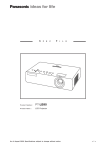
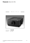
S
P
E
C
F
I
L
E
The PT-DW730LS and PT-DW730LK are not equipped with a lens.
P ro d u c t N u m b e r :
P ro d u c t N a m e :
PT-DW730S/DW730K
PT-DW730LS/DW730LK
DLP ™ Projectors
As of December 2011. Specifications and appearance are subject to change without notice.
SFD11M001-1
1/15
S
P
E
C
F
I
L
E
PT-DW730S/DW730K/DW730LS/DW730LK
DLP ™ Projectors
Specifications
Main unit
Power supply
Power consumption
120 V AC, 60 Hz
220–240 V AC, 50/60 Hz
DLP™ chip
Lens
Panel size
Display method
Pixels
PT-DW730S/DW730K
PT-DW730LS/DW730LK
Lamp
Screen size
Brightness* 2
Center-to-corner uniformity* 2
Contrast* 2
Resolution
Scanning frequency
DVI-D
RGB
YPBPR (YCBCR)
Video/S-Video
Optical axis shift
Keystone correction range
Installation
Terminals
DVI-D IN
RGB 1 IN
R, G, B
120 V AC, 7.5 A, 50/60 Hz
220–240 V AC, 4.3 A, 50/60 Hz
790 W (830 VA) (0.2 W with standby mode set to eco* 1 , 8 W with
standby mode set to normal. Both with fan stopped.)
760 W (950 VA) (0.3 W with standby mode set to eco* 1 , 9 W with
standby mode set to normal. Both with fan stopped.)
16.5 mm (0.65 in) diagonal (16:10 aspect ratio)
DLP™ chip × 1, DLP™ system
1,024,000 (1,280 × 800) × 1, total of 1,024,000 pixels
Powered zoom/focus lenses (1.8 – 2.5:1), F 1.7–1.9, f 25.6 – 35.7 mm
Optional powered zoom/focus lenses and fixed-focus lens
300 W (max. 310 W) UHM lamps (× 2) (dual lamp system)
1.27 –15.24 m (50 – 600 inches) (1.27– 5.08 m (50– 200 inches) with the
ET-DLE055), 16:10 aspect ratio
7,000 lumens (dual lamp, lamp mode: high)
90%
2,500:1 (full on/full off, contrast mode: high, brightness: 3,500 lumens)
1,280 × 800 pixels (Input signals that exceed this resolution will be
converted to 1,280 × 800 pixels.)
fH: 15 kHz – 91 kHz, fV: 50 Hz – 85 Hz, dot clock: 162 MHz or lower
fH: 15 kHz – 91 kHz, fV: 50 Hz – 85 Hz, dot clock: 150 MHz or lower
480i (525i):
fH 15.75 kHz; fV 60 Hz,
576i (625i):
fH 15.63 kHz; fV 50 Hz,
480p (525p):
fH 31.50 kHz; fV 60 Hz,
576p (625p):
fH 31.25 kHz; fV 50 Hz,
720 (750)/60p: fH 45.00 kHz; fV 60 Hz,
720 (750)/50p: fH 37.50 kHz; fV 50 Hz,
1035/60i:
fH 33.75 kHz; fV 60 Hz,
1080 (1125)/60i: fH 33.75 kHz; fV 60 Hz,
1080 (1125)/50i: fH 28.13 kHz; fV 50 Hz,
1080/25p:
fH 28.13 kHz; fV 25 Hz,
1080/24p:
fH 27.00 kHz; fV 24 Hz,
1080/24sF:
fH 27.00 kHz; fV 48 Hz,
1080/30p:
fH 33.75 kHz; fV 30 Hz,
1080/60p:
fH 67.50 kHz; fV 60 Hz,
1080/50p:
fH 56.25 kHz; fV 50 Hz
fH: 15.75 kHz, fV: 60 Hz [NTSC/NTSC4.43/PAL-M/PAL60]
fH: 15.63 kHz, fV: 50 Hz [PAL/PAL-N/SECAM]
Vertical: +60% (powered), horizontal: ±10% (powered)
Vertical: ±40° (±30° with the ET-DLE055 and ET-DLE080)
Ceiling/floor, front/rear
DVI-D 24-pin × 1, DVI 1.0 compliant, HDCP compatible, for single link
only
480p, 576p, 720/60p, 720/50p, 1080/60i, 1080/50i, 1080/24p,
1080/24sF, 1080/25p, 1080/30p, 1080/60p, 1080/50p,
VGA (640 × 480) – WUXGA* 3 (1,920 × 1,200), compatible with noninterlaced signals only, dot clock: 25–162 MHz
BNC × 5
R: 0.7 Vp-p, 75 ohms,
G: 0.7 Vp-p (G: 1.0 Vp-p for sync on G), 75 ohms,
B: 0.7 Vp-p, 75 ohms
HD/VD, SYNC: High impedance, TTL (positive/negative)
NOTE: HD/SYNC, and VD terminals do not accept tri-level sync signals.
Y, PB, PR (Y, CB, CR) Y: 1.0 Vp-p (including sync signal), PB/PR (CB/CR): 0.7 Vp-p, 75 ohms
As of December 2011
SFD11M001-1
2/15
S
P
E
C
F
I
DLP ™ Projectors
L
E
PT-DW730S/DW730K/DW730LS/DW730LK
RGB 2 IN
R, G, B
D-sub HD 15-pin × 1
R: 0.7 Vp-p, 75 ohms,
G: 0.7 Vp-p (G: 1.0 Vp-p for sync on G), 75 ohms,
B: 0.7 Vp-p, 75 ohms
HD/VD, SYNC: High impedance, TTL (positive/negative)
NOTE: HD/SYNC, and VD terminals do not accept tri-level sync signals.
Y, PB, PR (Y, CB, CR)
VIDEO IN
S-VIDEO IN
SERIAL IN
SERIAL OUT
REMOTE 1 IN
REMOTE 1 OUT
REMOTE 2 IN
LAN
Power cord length
Cabinet materials
Dimensions (W × H × D) PT-DW730S/DW730K
PT-DW730LS/DW730LK
Weight
Operation noise* 2
Operating temperature
Operating humidity
Remote control unit
Power supply
Operation range* 7
Dimensions (W × H × D)
Weight
PT-DW730S/DW730K
PT-DW730LS/DW730LK
Y: 1.0 Vp-p (including sync signal), PB/PR (CB/CR): 0.7 Vp-p, 75 ohms
BNC × 1, 1.0 Vp-p, 75 ohms
Mini DIN 4-pin × 1, Y: 1.0 Vp-p, C: 0.286 Vp-p, 75 ohms
D-sub 9-pin × 1 for external control (RS-232C compliant)
D-sub 9-pin × 1 for link control (RS-232C compliant)
M3 jack × 1 for wired remote control
M3 jack × 1 for link control
D-sub 9-pin × 1 for external control (parallel)
RJ-45 × 1 for network connection, 100Base-TX/10Base-T, compliant
with PJLink™
3.0 m (9 ft 10 in)
Molded plastic
498 mm × 175 mm* 4 × 466 mm* 5 (19-19/32˝ × 6-7/8˝ * 4 × 18-11/32˝ * 5 )
(with supplied lens)
498 mm × 175 mm* 4 × 432 mm* 5 (19-19/32˝ × 6-7/8˝ * 4 × 17˝ * 5 )
(without lens)
Approx. 16.3 kg (35.9 lbs) (with supplied lens)
Approx. 15.4 kg (34.0 lbs) (without lens)
39 dB (dual lamp operation, lamp mode: high),
35 dB (dual lamp operation, lamp mode: normal)
0°– 45°C (32°–113°F) * 6
20%– 80% (no condensation)
3 V DC (R6/AA type battery × 2)
Approx. 30 m (98 ft 5 in) when operated from directly in front of the
signal receptor
51 × 176 × 23 mm (2˝ × 6-15/16˝ × 29/32˝)
Approx. 134 g (4.7 oz) (including batteries)
Supplied accessories
Power cord (× 1)
Power cord security lock (× 1)
Wireless/wired remote control unit (× 1)
Batteries for remote control (R6/AA type × 2)
Optional accessories
Zoom lens (0.8–1.0:1)
Zoom lens (1.4– 2.0:1)
Zoom lens (2.4 – 3.8:1)
Zoom lens (3.8 – 5.7:1)
Zoom lens (5.6 – 9.0:1)
Fixed-focus lens (0.8:1)
Ceiling mount bracket
Replacement lamp unit
Replacement filter unit
ET-DLE080
ET-DLE150
ET-DLE250
ET-DLE350
ET-DLE450
ET-DLE055
ET-PKD56H (for high ceilings)
ET-PKD55S (for low ceilings)
ET-LAD60A
ET-LAD60AW (Twin Pack)
ET-EMF300
Weights and dimensions shown are approximate. Specifications and appearance are subject to change without notice.
*1 When the standby mode is set to eco, network functions such as power on over the LAN network will not operate, and the serial output terminal cannot be used. Also, only certain commands can be received for external control using the serial terminal.
*2 Measurement, measuring conditions, and method of notation all comply with ISO 21118 international standards.
*3 WUXGA resolution is supported only when the signals are compliant with VESA CVT-RB (Coordinated Video Timing-Reduced Blanking).
*4 With legs at shortest position.
*5 Protruding parts not included.
*6 The operating temperature range is 0°C to 40°C (32°F to 104°F) when the fan control is set to High Altitude mode (for altitudes from 1,400 m to
2,700 m (4,593 ft to 8,858 ft) above sea level). Also, if the ambient temperature exceeds 40°C (104°F) (35°C (95°F) in High Altitude mode) when
the projector is being used with Lamp Select set to Dual and Lamp Power set to High, the light output may be reduced approximately 20% to
protect the projector.
*7 Operation range differs depending on environments.
As of December 2011
SFD11M001-1
3/15
S
P
E
F
C
I
L
E
PT-DW730S/DW730K/DW730LS/DW730LK
DLP ™ Projectors
9 (11/32)
20 (25/32)
155 (6-3/32)
77.5
(3-1/16)
175 (6-7/8)
43 (1-11/16)
unit : mm (inch)
NOTE: This illustration is not drawn to scale.
The illustration shows the PT-DW730S/DW730K.
21 (13/16)
466 (18-11/32)
423 (16-21/32)
Dimensions
416 (16-3/8)
498 (19-19/32)
Terminals
1
2
3
R/PR
LAN
VIDEO IN
IN
S-VIDEO IN
B/PB
SYNC/HD
RGB1 IN
7
8
REMOTE 2
IN
RGB2 IN
9
10
As of December 2011
SFD11M001-1
SERIAL
5
VD
OUT
REMOTE 1
6
G/Y
4
OUT
DVI-D I N
1
Video input
7
Remote 1 input
2
S-Video input
8
Remote 1 output
Remote 2 input
3
RGB 1 input
9
4
RGB 2 Input
10 Serial input
5
DVI-D input
11 Serial output
6
LAN connector
11
4/15
S
P
E
C
F
I
L
E
PT-DW730S/DW730K/DW730LS/DW730LK
DLP ™ Projectors
H
Upper edge of projected image
416–496
(16-3/8–
19-17/32)
*2
340–420
(13-3/8–
16-17/32)
Standard setting-up position
*1 When the
A: 84 mm
43 mm
44 mm
45 mm
51 mm
95 mm
27 mm
lens protrudes to the maximum.
(3-5/16˝ ) with the ET-DLE080
(1-11/16˝ ) with the supplied lens
(1-23/32˝ ) with the ET-DLE150
(1-25/32˝ ) with the ET-DLE250
(2˝ ) with the ET-DLE350
(3-3/4˝ ) with the ET-DLE450
(1-1/16˝ ) with the ET-DLE055
L
*2 Adjustable in 40 mm (1-9/16˝) steps.
A* 1
168
(6-10/16)
Projected image
255
(10-1/32)
H
L
Lower edge of projected image
L
344
(13-17/32)
100
(3-15/16)
unit : mm (inch)
Projected image
100
(3-15/16)
400
(15-3/4)
NOTE:
Illustrations show the projector installed
using optional ceiling mount bracket
ET-PKD56H and an optional lens.
This illustration is not drawn to scale.
Caution:
• All construction work should be done by a qualified technician.
• When mounting to the ceiling, use the special mounting bracket. To prevent the projector from swaying or dropping, attach the wire between the mounting bracket and the ceiling.
As of December 2011
SFD11M001-1
5/15
S
P
E
F
C
I
L
E
PT-DW730S/DW730K/DW730LS/DW730LK
DLP ™ Projectors
Projection distance for 16:10 aspect ratio screen
Unit: meters
Screen size
(diagonal)
Distance to screen (L)
Zoom
ET-DLE080
Zoom lens
[m]
Height from the edge
of screen to
Fixed-focus center of lens (H)
ET-DLE150
Zoom lens
Supplied lens
ET-DLE250
Zoom lens
ET-DLE350
Zoom lens
ET-DLE450
Zoom lens
ET-DLE055
Fixed-focus
lens
Zoom
lenses
Fixedfocus
lens
[in]
min.
max.
min.
max.
min.
max.
min.
max.
min.
max.
min.
max.
1.27 / 50
0.87
1.09
1.45
2.12
1.91
2.70
2.54
4.06
4.00
6.11
5.96
9.60
0.87
-0.07 – 0.34
0.34
1.52 / 60
1.05
1.32
1.75
2.55
2.31
3.26
3.07
4.89
4.83
7.36
7.21
11.57
1.06
-0.08 – 0.40
0.40
1.78 / 70
1.24
1.54
2.05
2.98
2.71
3.81
3.59
5.72
5.65
8.61
8.46
13.55
1.24
-0.09 – 0.47
0.47
2.03 / 80
1.42
1.77
2.35
3.42
3.11
4.37
4.12
6.55
6.48
9.86
9.71
15.53
1.42
-0.11 – 0.54
0.54
2.29 / 90
1.60
2.00
2.65
3.85
3.50
4.92
4.64
7.38
7.31
11.11
10.96
17.51
1.61
-0.12 – 0.61
0.61
2.54 / 100
1.78
2.22
2.95
4.28
3.90
5.48
5.17
8.20
8.13
12.36
12.22
19.49
1.79
-0.14 – 0.67
0.67
3.05 / 120
2.15
2.68
3.55
5.15
4.70
6.59
6.21
9.86
9.79
14.86
14.72
23.45
2.16
-0.16 – 0.81
0.81
3.81 / 150
2.70
3.36
4.45
6.45
5.89
8.25
7.79
12.35
12.27
18.61
18.47
29.38
2.71
-0.20 – 1.01
1.01
5.08 / 200
3.62
4.49
5.95
8.61
7.88
11.03
10.41
16.49
16.40
24.85
24.73
39.28
3.63
-0.27 – 1.35
1.35
6.35 / 250
4.53
5.62
7.45
10.78
9.86
13.81
13.03
20.63
20.53
31.10
30.99
49.17
–
-0.34 – 1.68
–
7.62 / 300
5.45
6.76
8.96
12.95
11.85
16.58
15.65
24.77
24.67
37.35
37.25
59.06
–
-0.40 – 2.02
–
10.16 / 400
7.28
9.02
11.96
17.28
15.83
22.13
20.90
33.06
32.94
49.84
49.76
78.85
–
-0.54 – 2.69
–
12.70 / 500
9.11
11.29
14.96
21.61
19.80
27.68
26.14
41.34
41.20
62.33
62.28
98.64
–
-0.67 – 3.37
–
15.24 / 600
10.94
13.56
17.96
25.94
23.78
33.23
31.39
49.62
49.47
74.82
74.80 118.43
–
-0.81 – 4.04
–
Unit: feet
Screen size
(diagonal)
Distance to screen (L)
Zoom
ET-DLE080
Zoom lens
ET-DLE150
Zoom lens
Supplied lens
Fixed-focus
ET-DLE250
Zoom lens
ET-DLE350
Zoom lens
ET-DLE450
Zoom lens
Height from the edge
of screen to
center of lens (H)
ET-DLE055
Fixed-focus
lens
Zoom
lenses
Fixedfocus
lens
[in]
min.
max.
min.
max.
min.
max.
min.
max.
min.
max.
min.
max.
1.27 / 50
2.8
3.6
4.7
6.9
6.3
8.9
8.3
13.3
13.1
20.1
19.5
31.5
2.9
-0.2 – 1.1
1.1
1.52 / 60
3.5
4.3
5.7
8.4
7.6
10.7
10.1
16.0
15.8
24.2
23.6
38.0
3.5
-0.3 – 1.3
1.3
1.78 / 70
4.1
5.1
6.7
9.8
8.9
12.5
11.8
18.8
18.5
28.3
27.8
44.5
4.1
-0.3 – 1.6
1.6
2.03 / 80
4.7
5.8
7.7
11.2
10.2
14.3
13.5
21.5
21.3
32.3
31.9
51.0
4.7
-0.4 – 1.8
1.8
2.29 / 90
5.3
6.5
8.7
12.6
11.5
16.2
15.2
24.2
24.0
36.4
36.0
57.4
5.3
-0.4 – 2.0
2.0
2.54 / 100
5.9
7.3
9.7
14.0
12.8
18.0
16.9
26.9
26.7
40.5
40.1
63.9
5.9
-0.4 – 2.2
2.2
3.05 / 120
7.1
8.8
11.6
16.9
15.4
21.6
20.4
32.4
32.1
48.7
48.3
76.9
7.1
-0.5 – 2.7
2.7
3.81 / 150
8.9
11.0
14.6
21.2
19.3
27.1
25.5
40.5
40.2
61.0
60.6
96.4
8.9
-0.7 – 3.3
3.3
5.08 / 200
11.9
14.7
19.5
28.3
25.8
36.2
34.2
54.1
53.8
81.5
81.1
128.9
11.9
-0.9 – 4.4
4.4
6.35 / 250
14.9
18.4
24.5
35.4
32.4
45.3
42.8
67.7
67.4
102.0
101.7
161.3
–
-1.1 – 5.5
–
7.62 / 300
17.9
22.2
29.4
42.5
38.9
54.4
51.4
81.3
80.9
122.5
122.2
193.8
–
-1.3 – 6.6
–
10.16 / 400
23.9
29.6
39.2
56.7
51.9
72.6
68.6
108.4
108.1
163.5
163.3
258.7
–
-1.8 – 8.8
–
12.70 / 500
29.9
37.0
49.1
70.9
65.0
90.8
85.8
135.6
135.2
204.5
204.3
323.6
–
-2.2 – 11.0
–
15.24 / 600
35.9
44.5
58.9
85.1
78.0
109.0
103.0
162.8
162.3
245.5
245.4
388.5
–
-2.7 – 13.3
–
[m]
• The value for L (distance to screen) varies slightly within ±5% depending on the zoom lens characteristics.
• The zoom lens characteristics may cause slight image distortion.
1
• When vertical keystone correction is used, the image is corrected in the direction that reduces its projected size.
• The brightness varies depending on the zoom setting.
Note: When the ET-DLE055 is mounted, the optical lens shift function cannot be used.
As of December 2011
SFD11M001-1
6/15
S
P
E
F
C
I
L
E
PT-DW730S/DW730K/DW730LS/DW730LK
DLP ™ Projectors
Projection distance for 16:9 aspect ratio screen
Unit: meters
Screen size
(diagonal)
Distance to screen (L)
Zoom
ET-DLE080
Zoom lens
[m]
Height from the edge
of screen to
Fixed-focus center of lens (H)
ET-DLE150
Zoom lens
Supplied lens
ET-DLE250
Zoom lens
ET-DLE350
Zoom lens
ET-DLE450
Zoom lens
ET-DLE055
Fixed-focus
lens
Zoom
lenses
Fixedfocus
lens
[in]
min.
max.
min.
max.
min.
max.
min.
max.
min.
max.
min.
max.
1.27 / 50
0.89
1.12
1.49
2.18
1.97
2.78
2.62
4.18
4.11
6.29
6.13
9.87
0.90
-0.14 – 0.31
0.31
1.52 / 60
1.08
1.35
1.80
2.62
2.38
3.35
3.15
5.03
4.96
7.57
7.42
11.90
1.09
-0.16 – 0.37
0.37
1.78 / 70
1.27
1.59
2.11
3.07
2.79
3.92
3.69
5.88
5.81
8.85
8.70
13.94
1.28
-0.19 – 0.44
0.44
2.03 / 80
1.46
1.82
2.42
3.51
3.19
4.49
4.23
6.73
6.66
10.14
9.99
15.97
1.46
-0.22 – 0.50
0.50
2.29 / 90
1.65
2.05
2.72
3.96
3.60
5.06
4.77
7.58
7.51
11.42
11.28
18.01
1.65
-0.25 – 0.56
0.56
2.54 / 100
1.84
2.29
3.03
4.40
4.01
5.63
5.31
8.44
8.36
12.71
12.56
20.04
1.84
-0.27 – 0.62
0.62
3.05 / 120
2.21
2.75
3.65
5.29
4.83
6.77
6.39
10.14
10.06
15.27
15.14
24.11
2.22
-0.33 – 0.75
0.75
3.81 / 150
2.78
3.45
4.58
6.63
6.05
8.49
8.01
12.69
12.61
19.13
19.00
30.21
2.79
-0.41 – 0.93
0.93
5.08 / 200
3.72
4.62
6.12
8.86
8.10
11.34
10.70
16.95
16.86
25.55
25.43
40.38
3.73
-0.55 – 1.25
1.25
6.35 / 250
4.66
5.78
7.66
11.08
10.14
14.19
13.40
21.21
21.11
31.97
31.86
50.54
–
-0.69 – 1.56
–
7.62 / 300
5.60
6.94
9.21
13.31
12.18
17.04
16.09
25.46
25.36
38.39
38.29
60.71
–
-0.82 – 1.87
–
10.16 / 400
7.48
9.27
12.29
17.76
16.27
22.75
21.48
33.98
33.86
51.23
51.16
81.05
–
-1.10 – 2.49
–
12.70 / 500
9.36
11.60
15.38
22.21
20.36
28.46
26.87
42.49
42.35
64.07
64.02 101.39
–
-1.37 – 3.11
–
15.24 / 600
11.24
13.93
18.46
26.67
24.44
34.16
32.26
51.00
50.85
76.91
76.89 121.73
–
-1.64 – 3.74
–
Unit: feet
1
Screen size
(diagonal)
Distance to screen (L)
Zoom
ET-DLE080
Zoom lens
ET-DLE150
Zoom lens
Supplied lens
Fixed-focus
ET-DLE250
Zoom lens
ET-DLE350
Zoom lens
ET-DLE450
Zoom lens
Height from the edge
of screen to
center of lens (H)
ET-DLE055
Fixed-focus
lens
Zoom
lenses
Fixedfocus
lens
[in]
min.
max.
min.
max.
min.
max.
min.
max.
min.
max.
min.
max.
1.27 / 50
2.9
3.7
4.9
7.1
6.5
9.1
8.6
13.7
13.5
20.6
20.1
32.4
2.9
-0.5 – 1.0
1.0
1.52 / 60
3.5
4.4
5.9
8.6
7.8
11.0
10.3
16.5
16.3
24.8
24.3
39.1
3.6
-0.5 – 1.2
1.2
1.78 / 70
4.2
5.2
6.9
10.1
9.1
12.9
12.1
19.3
19.1
29.0
28.6
45.7
4.2
-0.6 – 1.4
1.4
2.03 / 80
4.8
6.0
7.9
11.5
10.5
14.7
13.9
22.1
21.9
33.3
32.8
52.4
4.8
-0.7 – 1.6
1.6
2.29 / 90
5.4
6.7
8.9
13.0
11.8
16.6
15.7
24.9
24.6
37.5
37.0
59.1
5.4
-0.8 – 1.8
1.8
2.54 / 100
6.0
7.5
9.9
14.4
13.2
18.5
17.4
27.7
27.4
41.7
41.2
65.7
6.0
-0.9 – 2.0
2.0
3.05 / 120
7.3
9.0
12.0
17.4
15.8
22.2
21.0
33.3
33.0
50.1
49.7
79.1
7.3
-1.1 – 2.5
2.5
3.81 / 150
9.1
11.3
15.0
21.7
19.9
27.8
26.3
41.6
41.4
62.7
62.3
99.1
9.1
-1.3 – 3.1
3.1
5.08 / 200
12.2
15.1
20.1
29.1
26.6
37.2
35.1
55.6
55.3
83.8
83.4
132.5
12.2
-1.8 – 4.1
4.1
6.35 / 250
15.3
19.0
25.1
36.4
33.3
46.6
44.0
69.6
69.3
104.9
104.5
165.8
–
-2.3 – 5.1
–
7.62 / 300
18.4
22.8
30.2
43.7
40.0
55.9
52.8
83.5
83.2
125.9
125.6
199.2
–
-2.7 – 6.1
–
10.16 / 400
24.5
30.4
40.3
58.3
53.4
74.6
70.5
111.5
111.1
168.1
167.8
265.9
–
-3.6 – 8.2
–
12.70 / 500
30.7
38.1
50.5
72.9
66.8
93.4
88.2
139.4
139.0
210.2
210.0
332.6
–
-4.5 – 10.2
–
15.24 / 600
36.9
45.7
60.6
87.5
80.2
112.1
105.9
167.3
166.8
252.3
252.2
399.4
–
-5.4 – 12.3
–
[m]
• The value for L (distance to screen) varies slightly within ±5% depending on the zoom lens characteristics.
• The zoom lens characteristics may cause slight image distortion.
• When vertical keystone correction is used, the image is corrected in the direction that reduces its projected size.
• The brightness varies depending on the zoom setting.
Note: When the ET-DLE055 is mounted, the optical lens shift function cannot be used.
As of December 2011
SFD11M001-1
7/15
S
P
E
C
F
I
L
E
PT-DW730S/DW730K/DW730LS/DW730LK
DLP ™ Projectors
Calculation of the projection distance
For a screen size different from the above, use the equation below to calculate the projection distance.
Aspect ratio 16:10
ET-DLE080
minimum
maximum
L (m) = (diagonal screen size in inches) × 0.0183 - 0.0471
L (m) = (diagonal screen size in inches) × 0.0227 - 0.0442
ET-DLE150
minimum
maximum
L (m) = (diagonal screen size in inches) × 0.0300 - 0.0540
L (m) = (diagonal screen size in inches) × 0.0433 - 0.0498
Supplied lens
minimum
maximum
L (m) = (diagonal screen size in inches) × 0.0398 - 0.0746
L (m) = (diagonal screen size in inches) × 0.0555 - 0.0725
ET-DLE250
minimum
maximum
L (m) = (diagonal screen size in inches) × 0.0524 - 0.0800
L (m) = (diagonal screen size in inches) × 0.0828 - 0.0792
ET-DLE350
minimum
maximum
L (m) = (diagonal screen size in inches) × 0.0827 - 0.1351
L (m) = (diagonal screen size in inches) × 0.1249 - 0.1346
ET-DLE450
minimum
maximum
L (m) = (diagonal screen size in inches) × 0.1251 - 0.3017
L (m) = (diagonal screen size in inches) × 0.1979 - 0.2991
ET-DLE055
(fixed focus)
L (m) = (diagonal screen size in inches) × 0.0184 - 0.0476
ET-DLE080
minimum
maximum
L (m) = (diagonal screen size in inches) × 0.0188 - 0.0471
L (m) = (diagonal screen size in inches) × 0.0233 - 0.0442
ET-DLE150
minimum
maximum
L (m) = (diagonal screen size in inches) × 0.0309 - 0.0540
L (m) = (diagonal screen size in inches) × 0.0445 - 0.0498
Supplied lens
minimum
maximum
L (m) = (diagonal screen size in inches) × 0.0409 - 0.0746
L (m) = (diagonal screen size in inches) × 0.0571 - 0.0725
ET-DLE250
minimum
maximum
L (m) = (diagonal screen size in inches) × 0.0539 - 0.0800
L (m) = (diagonal screen size in inches) × 0.0851 - 0.0792
ET-DLE350
minimum
maximum
L (m) = (diagonal screen size in inches) × 0.0850 - 0.1351
L (m) = (diagonal screen size in inches) × 0.1284 - 0.1346
ET-DLE450
minimum
maximum
L (m) = (diagonal screen size in inches) × 0.1286 - 0.3017
L (m) = (diagonal screen size in inches) × 0.2034 - 0.2991
ET-DLE055
(fixed focus)
L (m) = (diagonal screen size in inches) × 0.0189 - 0.0476
Aspect ratio 16:9
• Distances calculated with the above equations will include a slight error.
As of December 2011
SFD11M001-1
8/15
S
P
E
C
F
I
L
E
PT-DW730S/DW730K/DW730LS/DW730LK
DLP ™ Projectors
Shift range
Optical axis shift function allows to shift the position of a projected image as shown below.
• Floor mount
• Ceiling mount
(When the lens except the ET-DLE080 is mounted.)
(When the lens except the ET-DLE080 is mounted.)
H
0.1H
V
Standard postition
of projected image
0.6V
(Height of
projected image)
0.6V
V
0.1H
(Height of
projected image)
(Width of
projected image)
Standard postition
of projected image
0.1H
0.1H
H
(Width of
• Floor mount
• Ceiling mount
(When the ET-DLE080 is mounted.)
(When the ET-DLE080 is mounted.)
0.5V
Standard postition
of projected image
0.6V
0.6V
(Height of
projected image)
V
0.1H
0.5V
0.1H
V
(Width of
projected image)
(Height of
projected image)
H
0.1H
Standard postition
of projected image
0.1H
H
(Width of
projected image)
• The ET-DLE055 has a fixed short-focus lens. Therefore, the lens shift function provided in the main unit cannot be used.
Installable angle
Install the projector at an angle within the range shown below.
• Horizontal direction
The projector may be installed at a horizontal
angle of ±15°.
-1 5° +1 5°
360
°
• Vertical direction
The projector may be installed at a vertical
angle of 360°.
As of December 2011
SFD11M001-1
9/15
S
P
E
C
F
I
L
E
PT-DW730S/DW730K/DW730LS/DW730LK
DLP ™ Projectors
List of compatible signals
The signals that can be input to this projector are shown in the table below. Horizontal scanning frequencies of 15 kHz to 91 kHz, vertical scanning frequencies of 50 Hz to 85 Hz, and a dot clock of
150 MHz maximum can be input.
NOTE:
The native resolution of this projector is 1,024 × 800 pixels. If the display resolution of the input signal is different from the
native resolution, image compression or expansion will be used to convert the input signal to a level within the native resolution.
Display mode
NTSC/NTSC4.43/PAL-M/PAL60
PAL/PAL-N/SECAM
480i (525i)
576i (625i)
480p (525p)
576p (625p)
720/60p
720/50p
1080/60i
1080/50i
1080/24p
1080/24sF
1080/25p
1080/30p
1080/60p
1080/50p
VGA400
Display
resolution
(dots)1
720 × 480i
720 × 576i
720 × 480i
720 × 576i
720 × 483
720 × 576
1,280 × 720
1,920 × 1,080i
1,920 × 1,080
1,920 × 1,080i
1,920 × 1,080
640 × 400
VGA480
640 × 480
SVGA
800 × 600
MAC16
XGA
832 × 624
1,024 × 768
MXGA
1,152 × 864
MAC21
1280 × 768
1,152 × 870
1,280 × 768
1280 × 800
1,280 × 800
MSXGA
SXGA
1,280 × 960
1,280 × 1,024
SXGA+
1,400 × 1,050
WXGA+
UXGA
WSXGA+
1920 × 1080 3
1,440
1,600 ×
1,680 ×
1,920 ×
1,920 ×
WUXGA 3
× 900
1,200
1,050
1,080
1,200
Scanning frequency
H
V
(kHz)
(kHz)
15.7
15.6
15.7
15.6
31.5
31.3
45.0
37.5
33.8
28.1
27.0
27.0
28.1
33.8
67.5
56.3
31.5
37.9
31.5
35.0
37.9
37.5
43.3
35.2
37.9
48.1
46.9
53.7
49.7
39.6
48.4
56.5
60.0
65.5
68.7
80.0
96.7
64.0
67.5
76.7
68.7
39.6
47.8
41.3
49.7
60.0
64.0
80.0
91.1
64.0
82.2
55.9
75.0
65.3
66.6
74.0
59.9
50.0
59.9
50.0
59.9
50.0
60.0
50.0
60.0
50.0
24.0
24.0
50.0
60.0
60.0
50.0
70.1
85.1
59.9
66.7
72.8
75.0
85.0
56.3
60.3
72.2
75.0
85.1
74.6
50.0
60.0
70.1
75.0
81.6
85.0
100.0
120.0
71.2
74.9
85.0
75.1
49.9
59.9
50.0
59.8
60.0
60.0
75.0
85.0
60.0
75.0
59.9
60.0
60.0
59.9
60.0
Dot clock
frequency
(MHz)
−
−
13.5
13.5
27.0
27.0
74.3
74.3
74.3
74.3
74.3
74.3
74.3
74.3
148.5
148.5
25.2
31.5
25.2
30.2
31.5
31.5
36.0
36.0
40.0
50.0
49.5
56.3
57.3
51.9
65.0
75.0
78.8
86.0
94.5
105.0
130.0
94.2
108.0
121.5
100.0
65.3
79.5
68.0
83.5
108.0
108.0
135.0
157.5
108.0
155.9
106.5
162.0
146.3
138.5
154.0
Picture
quality 2
A
A
A
A
A
A
AA
AA
A
A
A
A
A
A
A
A
A
A
A
A
A
A
A
A
A
A
A
A
A
A
A
A
A
A
A
A
A
A
A
A
A
AA
AA
AA
AA
A
A
A
B
A
B
A
B
A
A
A
Format
VIDEO/S-VIDEO
YP B P R /RGB
YP B P R /RGB/DVI-D
RGB/DVI-D
1. The “i” appearing after the resolution indicates an interlaced signal.
2. The following symbols are used to indicate picture quality.
AA
Maximum picture quality can be obtained.
A
Signals are converted by the image processing circuit before picture is projected.
B
Pixels are thinned (or the image is converted by an image processing circuit for DVI-D signal input) before the picture is projected.
3. Compliant with VESA CVT-RB (Coordinated Video Timing-Reduced Blanking).
As of December 2011
SFD11M001-1
10/15
S
P
E
F
C
I
L
E
PT-DW730S/DW730K/DW730LS/DW730LK
DLP ™ Projectors
Serial connector
The serial connector complies with RS-232C. To control the projector from a personal computer, commands must be input through communication software, based on the format and satisfying the communication conditions shown below.
Pin assignments and signal names
6
No.
1
2
3
4
5
9
1
5
Signal name
–
TXD
RXD
–
GND
Description
NC
Send data
Receive data
Connected internally
Ground
No.
6
7
8
9
Signal name
–
CTS
RTS
–
Description
NC
Connected internally
Connected internally
NC
Description
NC
Receive data
Send data
Connected internally
Ground
No.
6
7
8
9
Signal name
–
RTS
CTS
–
Description
NC
Connected internally
Connected internally
NC
D-sub 9-pin (female) Serial input
Pin assignments and signal names
9
No.
1
2
3
4
5
6
5
1
Signal name
–
RXD
TXD
–
GND
D-sub 9-pin (male) Serial output
Communication conditions (factory setting)
Signal level
Synchronization method
Baud rate
Parity
Character length
Stop bit
X parameter
S parameter
RS-232C-compliant
Start-stop synchronization
9,600 bps
None
8 bits
1 bit
None
None
Basic format
Transmission from the computer begins with STX, then the ID, command, parameter, and ETX are sent
in this order. Add parameters according to the details of control.
STX
A
D
I1 I2
;
C1 C2 C3
Start
(2 byte)
Semicolon
(1 byte)
(1 byte)
ID: 2 characters
(2 bytes)
01 to 64: Address number
0A to 0Z: Group ID
ZZ: All units (ID ALL)
:
Colon
(1 byte)
P1 P2 ... Pn
ETX
End
(1 byte)
Parameters
(undefined length)
Command
(3 bytes)
(Control and/or query commands)
ID designator
CAUTION
• It may not be possible to send or receive commands for about 10 to 60 seconds when the lamp is first turned on. If this
occurs, wait for 60 seconds, then try sending or receiving again.
• When sending multiple commands, be sure to wait for at least 0.5 second after receiving a response from the projector before
sending the next command.
• Additional time is sometimes required for response due to processing inside the projector. Set the time-out period for command response to 10 seconds or more.
• When using two or more units:
1) Set different IDs for each unit.
2) Designate only one unit as RESPONSE (ID ALL) ON and the rest as RESPONSE (ID ALL) OFF.
3) Each group should have only one RESPONSE (ID GROUP) ON and the rest should be RESPONSE (ID GROUP) OFF.
As of December 2011
SFD11M001-1
11/15
S
P
E
C
F
I
L
E
DLP ™ Projectors
Cable specifications
PT-DW730S/DW730K/DW730LS/DW730LK
Projector
1
PC (DTE)
NC
NC
2
2
3
3
4
NC
NC
NC
NC
6
7
7
8
8
9
4
5
5
6
1
NC
NC
9
Control commands
*
Command : Parameter
Function
PON
POF
IIS:DVI
IIS:RG1
IIS:RG2
IIS:VID
IIS:SVD
LPM:0
LPM:1
LPM:2
LPM:3
OSH:0
OSH:1
OFZ:0
OFZ:1
OAS
VPM:NAT
VPM:STD
VPM:DYN
VPM:CIN
VPM:GRA
VXX:DLVI0=+0 0000
VXX:DLVI0=+0 0001
VXX:DLVI0=+0 0002
VXX:DLVI0=+0 0003
OTE:1
OTE:2
OTE:4
OTE:10
TSD:y1y2y3y4 m1m2d1d2w
TST:h1h2m1m2 s1s2
OOS:0
OOS:1
POWER (STANDBY)
INPUT SELECT
LAMP SELECT
SHUTTER
FREEZE
Callback
Standby power on
Standby power off
DVI-D
RGB 1
RGB 2
Video
S-Video
Dual (two lamps)
Single lamp
Lamp 1
Lamp 2
Shutter on
Shutter off
Off
On
AUTO SETUP
Natural
Standard
Dynamic
Cinema
Graphic
SYSTEM DAYLIGHT VIEW 2 Off
1
2
3
COLOR TEMPERATURE
Middle
High
User
Default
DATE
Date setting
TIME
Time setting
ON SCREEN
On-screen display off
On-screen display on
PICTURE MODE
PON
POF
IIS:DVI
IIS:RG1
IIS:RG2
IIS:VID
IIS:SVD
LPM:0
LPM:1
LPM:2
LPM:3
OSH:0
OSH:1
OFZ:0
OFZ:1
OAS
VPM:NAT
VPM:STD
VPM:DYN
VPM:CIN
VPM:GRA
VXX:DLVI0=+00000
VXX:DLVI0=+00001
VXX:DLVI0=+00002
VXX:DLVI0=+00003
OTE:1
OTE:2
OTE:4
OTE:10
TSD:y1y2y3y4m1m2d1d2w
TST:h1h2m1m2s1s2
OOS:0
OOS:1
Do not send PON, POF or OSH commands continuously in a short period of time. Doing so may burst the lamp or shorten the lamp replacement
cycle.
*
When a command that cannot be executed during standby mode is sent, the projector will send an ER401 command in reply.
As of December 2011
SFD11M001-1
12/15
S
P
E
C
F
I
L
E
PT-DW730S/DW730K/DW730LS/DW730LK
DLP ™ Projectors
Status request commands
Command : Parameter
QPW
Function
Main power status
QSH
Shutter function status
QFZ
Freeze function status
QIN
Input signal status
QOS
On-screen display status
QST
Q$L:1
Q$L:2
QSL
Projector run time
Lamp 1 run time
Lamp 2 run time
Lamp operation mode status
QLP
Lamp power mode status
QPM
Picture mode status
QVX:DLVI0
System daylight view status
QTM:0
QTM:1
QTM:2
QGD
QGT
Temperature status
Callback
000
001
0
1
0
1
DVI
RG1
RG2
VID
SVD
0
1
p1p2p3p4p5
p1p2p3p4
p1p2p3p4
0
1
2
3
0
1
NAT
STD
DYN
CIN
GRA
DLVI0=+00000
DLVI0=+00001
DLVI0=+00002
DLVI0=+00003
p1p2p3p4/p5p6p7p8 (*1)
Date setting status
Time setting status
y1y2y3y4m1m2d1d2w
h1h2m1m2s1s2
Description
Standby (Off)
On
Off
On
Off
On
DVI-D
RGB 1
RGB 2
Video
S-Video
Off
On
00000h –99999h
0000h –9999h
0000h –9999h
Dual
Single
Lamp 1
Lamp 2
High
Low
Natural
Standard
dynamic
Cinema
Graphic
Off
1
2
3
p0 = Intake air
p1 = Exhaust air
p2 = DLP™ chip
yyyymmdd (day of week) (*2)
hhmmss
* 1 p1p2p3p4: Celsius (°C), p5p6p7p8: Fahrenheit (°F)
* 2 Day of week: Monday = 1, Tuesday = 2, ... Sunday = 7
NOTE: If a wrong command is received, the projector will send an ER401 or ER402 command to the computer.
Command example
To set the on-screen display off, send the command as shown below.
STX
Start
ADZZ ;
ID Address
OOS
:
Command
0
ETX
Parameter
End
NOTE: When sending commands without parameters, a colon (:) is not necessary.
As of December 2011
SFD11M001-1
13/15
S
P
E
C
F
I
L
E
DLP ™ Projectors
PT-DW730S/DW730K/DW730LS/DW730LK
Notes on projector placement and operation
The projector uses a high-wattage lamp that becomes very hot during operation. Please observe the
following precautions.
1.
Never place objects on top of the projector.
2.
Make sure there is an unobstructed space of 500 mm (19-11/16˝) or more around the projector’s
exhaust openings.
3.
Do not stack projector units directly on top of one another for the purpose of multiple (stacked)
projection. When stacking projector units, be sure to provide the amount of space indicated below
between them. These space requirements also apply to installations where only one projector unit
is operating at one time and the other unit is used as a backup.
4.
Make sure that nothing blocks the projector’s air intake and exhaust openings. Also, install the projector so that cool or hot air from other air conditioning equipment does not flow directly toward
the projector’s air intake or exhaust openings.
5.
Do not install the projector in an enclosed space. If it is necessary to install it in an enclosed
space, add a separate ventilation system. If ventilation is insufficient, hot air will accumulate at the
intake opening. This may cause the projector’s protective circuit to interrupt projector operation.
6.
If the projector is installed in an enclosed space, ensure that the projector’s intake and exhaust
openings are not blocked. Take particular care to ensure that hot air from the exhaust openings is
not sucked into the intake openings.
7.
When installing the projector in any manner other than floor mounting with the adjuster legs, use
the five threaded ceiling mount holes (screw diameter: M6, projector interior thread length: 12 mm)
to secure the projector.
500 mm (19-11/16 ˝ )
or more
500 mm (19-11/16 ˝ ) or more
100 mm
( 3-15/16 ˝ )
or more
500 mm (19-11/16 ˝ )
or more
Do not stack projector
units directly on top of
one another.
Direction of air intake and exhaust
Intake
Exhaust
As of December 2011
SFD11M001-1
14/15
S
P
E
C
F
DLP ™ Projectors
I
L
E
PT-DW730S/DW730K/DW730LS/DW730LK
Operating the projector continuously
1.
If the projector is to be operated continuously for 24 hours, use the dual-lamp optical system's alternating lamp operation (lamp relay) function. Continuously operating the projector for 24 hours in the duallamp mode is not recommended. Allow a minimum of two hours per day of non-operation time for each
lamp if the projector is to be operated continuously for more than 22 hours.
2.
The lamp replacement cycle duration becomes shorter if the projector is operated repeatedly for short
periods.
Weights and dimensions shown are approximate. Specifications and appearance are subject to change without notice.
Product availability differs depending on region and country. This product may be subject to export control regulations.
DLP and the DLP logo are trademarks of Texas Instruments.
PJLink is a registered trademark, or a trademark application has been filed, in Japan, the United States, and other countries and regions.
All other trademarks are the property of their respective trademark owners.
As of December 2011
SFD11M001-1
15/15