1
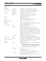
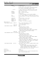
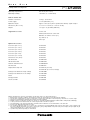
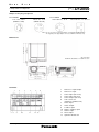
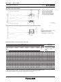
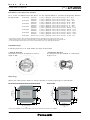
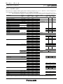
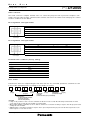
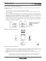
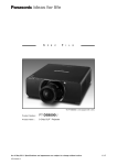
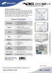
S
P
E
C
P ro d u c t N u m b e r :
PT-D12000
P ro d u c t N a m e :
3-Chip DLP™ Projector
F
I
L
E
As of July 2008. Appearance and specifications are subject to change without notice.
< 1 >
S
P
E
C
F
I
L
E
PT-D12000
3-Chip DLP™ Projector
Specifications
Main Unit
Power supply:
North America:
120–240 V AC, 16 – 9.0 A, 50/60 Hz (3-wire single-phase)
Europe, Asia
220–240 V AC, 9.5 A, 50/60 Hz (3-wire single-phase)
Power consumption:
North America:
1,600–1,500 W (10-15 W in standby mode with fan stopped)
Europe, Asia
1,500 W (15 W in standby mode with fan stopped)
DLP™ chip:
Panel size:
0.95˝ diagonal (4:3 aspect ratio)
Display method:
DLP™ chip x 3 (R, G, B), DLP™ projection system
Pixels:
1,470,000 (1,400 x 1,050) x 3, total of 4,410,000 pixels
Lens:
Optional powered zoom/focus lenses
Lamp:
300 W UHM™ lamp x 4
Screen size:
70 – 600 inches, 4:3 aspect ratio
(70 – 300 inches with the ET-D75LE5, 4:3 aspect ratio)
Brightness * :
12,000 lumens (four-lamp operation mode)
Center-to-corner uniformity * 1:
90%
Contrast * :
5,000:1 (full on/full off, in dynamic iris 3 mode)
Resolution:
1,400 x 1,050 pixels (Input signals that exceed this resolution will be
1
1
converted to 1,400 x 1,050 pixels.)
Scanning frequency:
RGB:
Horizontal: 15 –100 kHz, Vertical: 24 –120 Hz* 2,
Dot clock: 20–162 MHz
YPBPR (YCBCR):
480i: fH 15.75 kHz; fV 60 Hz, 576i: fH 15.63 kHz; fV 50 Hz,
480p: fH 31.50 kHz; fV 60 Hz, 576p: fH 31.25 kHz; fV 50 Hz,
720/60p: fH 45.00 kHz; fV 60 Hz, 720/50p: fH 37.50 kHz; fV 50 Hz,
1035/60i: fH 33.75 kHz; fV 60 Hz, 1080/60i: fH 33.75 kHz; fV 60 Hz,
1080/50i: fH 28.13 kHz; fV 50 Hz, 1080/25p: fH 28.13 kHz; fV 25 Hz,
1080/24p: fH 27.00 kHz; fV 24 Hz, 1080/24sF: fH 27.00 kHz; fV 48 Hz,
1080/30p: fH 33.75 kHz; fV 30 Hz, 1080/60p: fH 67.50 kHz; fV 60 Hz,
1080/50p: fH 56.25 kHz; fV 50 Hz
S-Video/Video:
Horizontal: 15.75/15.63 kHz, Vertical: 50/60 Hz,
(NTSC, NTSC4.43, PAL, PAL60, PAL-N, PAL-M, SECAM)
Optical axis shift* 3:
Vertical:
±50% (±40% with the ET-D75LE6) from center of screen, powered
Horizontal:
±30% (±20% with the ET-D75LE6) from center of screen, powered
Keystone correction range:
Vertical: ±40° (±22° with the ET-D75LE5, ±28° wih the ET-D75LE6),
with geometric adjustment: vertical ±10°, horizontal ±15°
Installation:
Terminals:
Ceiling/floor, front/rear
DVI-D IN:
DVI-D 24-pin x 1, DVI 1.0 compliant, compatible with HDCP, compatible with single link only,
480p, 576p, 720/60p, 720/50p, 1080/60i, 1080/50i, 1080/24p,
1080/24sF, 1080/25p, 1080/30p, 1080/60p, 1080/50p
VGA (640 x 480) – WUXGA*4 (1,920 x 1,200), compatible with noninterlaced signals only, dot clock: 25–162 MHz
RGB1 IN:
R, G, B:
BNC x 5
G: 0.7 Vp-p (1.0 Vp-p for sync on G), 75 ohms,
B, R: 0.7 Vp-p, 75 ohms
HD, VD, SYNC: 1.4–5.0 Vp-p, positive/negative automatic
Y, PB, PR
Y: 1.0 p-p, 75 ohms (incl. sync signal), PB/PR: 0.7 Vp-p, 75 ohms
0.7 Vp-p (1.0 Vp-p for sync on G), 75 ohms
NOTE: HD/SYNC, and VD terminals do not accept 3-value direct sync signals.
As of July 2008
< 2 >
S
P
E
C
F
I
L
E
PT-D12000
3-Chip DLP™ Projector
RGB2 IN:
D-sub HD 15-pin x 1
R, G, B:
0.7 Vp-p (1.0 Vp-p for sync on G), 75 ohms
HD, VD, SYNC: TTL, high impedance, positive/negative automatic
VD: 1.4–5.0 Vp-p, positive/negative automatic, 75 ohms
Y, PB, PR
Y: 1.0 p-p, 75 ohms (incl. sync signal), PB/PR: 0.7 Vp-p, 75 ohms
NOTE: HD/SYNC, and VD terminals do not accept 3-value direct sync signals.
VIDEO IN:
BNC x 1, 1.0 Vp-p, 75 ohms
VIDEO OUT:
BNC x 1, 1.0 Vp-p, active through
S-VIDEO IN:
Mini DIN 4-pin x 1
Y: 1.0 Vp-p, C: 0.286 Vp-p, 75 ohms (S1 signal compatible)
LAN:
RJ-45 x 1, 10Base-T/100Base-TX, compatible with PJLink™ (class 1)
SERIAL IN * :
D-sub 9-pin (female) x 2, for external control (RS-232C/RS-422 compli-
5
ant)
SERIAL OUT * :
D-sub 9-pin (male) x 1, for link control
REMOTE 1 IN:
M3 jack x 1 for wired remote control
REMOTE 1 OUT:
M3 jack x 1 for link control
REMOTE 2 IN:
D-sub 9-pin x 1 for external control (parallel)
5
Optional board slot * :
6
With ET-MD77SD1 installed:
SERIAL IN:
BNC x 1, SD-SDI signal (YCBCR 4:2:2 10-bit):
SERIAL OUT:
BNC x 1, active through
SERIAL IN:
BNC x 1
SMPTE 259M compliant: 480i, 576i
With ET-MD77SD3 installed:
SD-SDI signal (YCBCR 4:2:2 10-bit):
SMPTE 259M compliant: 480i, 576i
Single-link HD-SDI signal (YCBCR 4:2:2 10-bit):
SMPTE 292M compliant: 720/50p, 720/60p, 1035/60i, 1080/50i,
1080/60i, 1080/25p, 1080/24p, 1080/24sF, 1080/30p
SERIAL OUT:
With ET-MD100SD4 installed:
BNC x 1, active through
Link A/Link B IN: BNC x 1 for each
SD-SDI signal (YCBCR 4:2:2 10-bit):
SMPTE 259M compliant: 480i, 576i
Single-link HD-SDI signal (YCBCR 4:2:2 10-bit):
SMPTE 292M compiant: 720/50p, 720/60p, 1080/50i, 1080/60i,
1080/25p, 1080/24p, 1080/24sF, 1080/30p
Dual-link HD-SDI signal (RGB 4:4:4 12-bit/10-bit):
SMPTE 372M compiant: 1920 x 1080/50i, 1920 x 1080/60i, 1920 x
1080/25p, 1920 x 1080/24p, 1920 x 1080/24sF, 1920 x 1080/30p
Dual-link HD-SDI signal (X´Y´Z´ 4:4:4 12-bit):
2048 x 1080/24p, 2048 x 1080/24sF
With ET-MD77DV installed:
DVI-D IN:
DVI-D 24-pin x 1, DVI 1.0 compliant, compatible with HDCP, compatible with single link only,
480p, 576p, 720/60p, 720/50p, 1080/60i, 1080/50i, 1080/24p,
1080/24sF, 1080/25p, 1080/30p, 1080/60p, 1080/50p
VGA (640 x 480) – WUXGA*4 (1,920 x 1,200), compatible with noninterlaced signals only, dot clock: 25–162 MHz
Power cord:
3 m/9.8´
Cabinet material:
Moulded plastic
Dimensions (W x H x D):
578 x 320 x 643 mm (22-3/4˝ x 12-19/32˝ x 25-5/16˝) (without lens)
Weight*7:
Approx. 35 kg (77.2 lbs) (without lens)
As of July 2008
< 3 >
S
P
E
C
F
I
L
E
PT-D12000
3-Chip DLP™ Projector
Operating temperature*8:
0°C–45°C (32°F–113°F)
Operating humidity:
10%–80% (no condensation)
Remote Control Unit
Number of functions:
35 keys, 39 functions
Power supply:
3 V DC (AA battery x 2)
Operation range*9:
Approx. 30 m (98.4´) when operated from directly signal receptor
Dimensions (W x H x D):
51 x 22.7 x 176 mm (2˝ x 7/8˝ x 6-15/16˝)
Weight:
134 g (4.7 oz) (including batteries)
Supplied Accessories
Power cord
Wireless/wired remote control unit
Batteries for remote control (x 2)
Eye bolts (x 4)
Wire rope
Optional Accessories
Zoom lens (0.9 –1.1:1):
ET-D75LE6
Zoom lens (1.4 –1.8:1):
ET-D75LE1
Zoom lens (1.8 – 2.8:1):
ET-D75LE2
Zoom lens (2.8 – 4.6:1):
ET-D75LE3
Zoom lens (4.6 –7.4:1):
ET-D75LE4
Zoom lens (7.3 –13.8:1):
ET-D75LE8
Fixed-focus lens (0.7:1):
ET-D75LE5
SD-SDI board:
ET-MD77SD1
HD/SD-SDI board:
ET-MD77SD3
Dual link HD-SDI board:
ET-MD100SD4
DVI-D board:
ET-MD77DV
Replacement lamp unit
ET-LAD12K (one unit)
ET-LAD12KF (a set of four lamps)
Ceiling mount bracket for high ceilings
ET-PKD100H
Ceiling mount bracket for low ceilings
ET-PKD100S
Frame
ET-PFD100
Carrying handle
ET-HAD100
Smoke cut filter
ET-SFD100
Weights and dimensions shown are approximate. Specifications subject to change without notice.
*1 Measurement, measuring conditions, and method of notation all comply with ISO 21118 international standards.
*2 Smooth image reproduction may not be possible when a motion video signal with a vertical frequency other than 50 or 60 Hz is input.
*3 Shift range is limited during simultaneous horizontal and vertical shifting.
*4 WUXGA resolution is supported only when the signals are compliant with VESA CVT-RB (Coordinated Video Timing-Reduced Blanking).
*5 Contact your dealers for details when the control using RS-232C or RS-422 is required.
*6 The LAN terminal on the optional board will be inactivated after installation. Use the LAN terminal on the main unit.
*7 Average value. May differ depending on models.
*8 The operating temperature range is 0°C (32°F) to 40°C (104°F) when used in High-Altitude mode (1,400 m [4,593 feet] to 2,700 m [8,858 feet]).
Also, if the ambient temperature exceeds 40°C (104°F) (35°C [95°F] in High-Altitude mode) when using all four lamps, the light output may be
reduced approximately 30% to protect the projector.
*9 Operation range differs depending on environments.
As of July 2008
< 4 >
S
P
E
F
C
I
L
E
PT-D12000
3-Chip DLP™ Projector
Shape of the plug receptacle
PT-D12000U
PT-D12000E
125 V AC, 20 A
(NEMA 5-20R)
250 V AC, 15 A
(NEMA 6-15R)
Note:
220-240V AC, 16 A
220-240V AC, 13 A/15 A
Be sure to use the power plug adaptor cord supplied with the projector.
The supplied power plug adaptor can be used with the PT-D12000 only.
607
(23-29/32˝)
643 (25-5/16˝)
Dimensions
120
(4-23/32˝)
265 (10-7/16˝)
320 (12-19/32˝)
218 (8-19/32˝)
36
(1-13/32˝)
unit : mm (inch)
NOTE: This illustration is not drawn to scale.
477
(18-25/32˝)
448 (17-5/8˝)
578 (22-3/4˝)
Terminals
1
7 8
2
9
As of July 2008
3
10
4
11
5
12 13
6
1
2
3
4
5
6
7
8
9
10
11
12
13
Remote 1 input/output
Remote 2 input
Serial input (RS-232C)
Serial input (RS-422)
Serial output (RS-422)
LAN connector
(10Base-T/100Base-TX)
Video input
Video output
S-Video input
RGB 1 (YP B P R ) input
RGB 2 Input
DVI-D input
Optional board slot
< 5 >
S
P
E
F
C
I
L
E
PT-D12000
3-Chip DLP™ Projector
Standard setting-up positions
416.5– 536.5
(16-13/32˝–
21-1/8˝)
*1 When the lens protrudes to the maximum.
163
L
*1
Projected image
414 mm (16-5/16˝) with the ET-D75LE6
316.5 mm (12-15/32˝) with ET-D75LE1
301 mm (11-27/32˝) with the ET-D75LE2
304.5 mm (12˝) with the ET-D75LE3
328.4 mm (12-15/16˝) with the ET-D75LE4
456.5 mm (17-31/32˝) with the ET-D75LE8
404.5 mm (15-15/16˝) with the ET-D75LE5
(6-13/32˝)
H
Upper edge of projected image
H
L
unit : mm (inch)
157
(6-3/16˝)
Lower edge of projected image
NOTE:
Illustrations show the projector installed
using optional ceiling bracket
ET-PKD100H and an optional lens.
L
This illustration is not drawn to scale.
87.5
(3-7/16˝)
Projected image
Projection distance (screen aspect ratio 4:3)
Distance to screen
Zoom
Lens
(Throw ratio)
ET-D75LE6
Zoom lens
(1.0–1.2:1)
ET-D75LE1
Zoom lens
(1.5– 2.0:1)
ET-D75LE2
Zoom lens
(2.0– 3.0:1)
ET-D75LE3
Zoom lens
(3.0– 5.0:1)
ET-D75LE4
Zoom lens
(5.0 –8.0:1)
ET-D75LE8
Zoom lens
(7.9–15.0:1)
min.
max.
min.
max.
min.
max.
min.
max.
min.
min.
70
1,393
4.6
1,662
5.5
4,215
13.8
4,226
13.9
7,094
23.3
7,101 11,374
37.3
23.3
11,091 21,142
69.4
36.4
1,600
5.2
1,910
6.3
2,768
9.1
3,178
10.4
3,588
11.8
3,998
13.1
4,817
15.8
6,047
19.8
8,096
26.6
2,801
9.2
80
2,072
6.8
2,379
7.8
2,686
8.8
2,992
9.8
3,606
11.8
4,526
14.8
6,060
19.9
7,594
24.9
9,128
29.9
12,196
40.0
15,264
50.0
18,332
60.1
3,212
10.5
4,832
15.9
4,843
15.9
8,125
26.7
8,132 13,013
42.7
26.7
12,730 24,214
79.4
41.8
3,624
11.9
5,449
17.9
5,460
17.9
9,156
30.0
9,163 14,652
48.1
30.1
14,370 27,286
89.5
47.1
4,035
13.2
6,067
19.9
6,077 10,187
33.4
19.9
10,193 16,292
53.5
33.4
16,009 30,358
99.6
52.5
4,858
15.9
7,301
24.0
7,312 12,248
40.2
24.0
12,255 19,570
64.2
40.2
19,288 36,501
63.3
119.8
6,093
20.0
Screen
size
(inch,
diagonal)
90
1,807
5.9
2,158
7.1
100
2,014
6.6
2,406
7.9
120
2,428
8.0
2,902
9.5
150
3,049
10.0
3,646
12.0
200
4,084
13.4
4,886
16.0
250
5,119
16.8
6,126
20.4
300
6,154
20.2
7,366
24.2
8,224
27.0
9,846
32.3
400
500
10,294 12,326
33.8
40.4
600
12,364 14,806
48.6
40.6
max.
ET-D75LE5
Fixed-focus
lens
(0.8:1)
max.
9,153
30.0
9,164 15,341
50.3
30.0
15,348 24,488
80.3
50.4
24,207 45,717
79.4
150.0
8,150 12,240
40.2
26.7
12,250 20,496
67.2
40.2
20,502 32,685
107.2
67.3
32,404 61,076
106.3
200.4
10,145
33.3
10,208 15,326
50.3
33.5
15,337 25,650
84.2
50.3
25,657 40,881
134.1
84.2
40,602 76,435
133.2
250.8
12,194
40.0
12,265 18,413
60.4
40.2
18,423 30,805
101.1
60.4
30,811 49,078
161.0
101.1
48,799 91,794
160.1
301.2
16,292
53.5
16,380 24,586
80.7
53.7
24,596 41,114
134.9
80.7
41,120 65,471
214.8
134.9
65,194 122,512
213.9
401.9
20,390
66.9
20,495 30,759
100.9
67.2
30,769 51,423
168.7
100.9
51,429 81,864
268.6
168.7
81,589 153,230
267.7
502.7
24,488
80.3
24,610 36,932
121.2
80.7
36,942 61,732
202.5
121.2
61,738 98,257
322.4
202.6
97,984 183,948
321.5
603.5
1,022
3.4
1,180
3.9
1,338
4.4
1,496
4.9
1,812
5.9
2,286
7.5
3,076
10.1
3,866
12.7
4,656
15.3
-
• The figures in the above table may vary by approximately ±5% depending on the projection lens that is used.
• When vertical keystone correction is used, the image is corrected in the direction that reduces its projected size.
• At the shortest projection distance, the zoom lens characteristics may cause slight image distortion.
*2: The shift range function does not operate when the fixed-focus lens is installed.
As of July 2008
Height from the
edge of screen to
center of lens (H)
Fixed-focus
Zoom lenses
Zoom lenses
except
ET-D75LE6
0
0
0
0
0
0
0
0
0
0
0
0
0
0
0
0
0
0
0
0
0
0
0
0
– 1,067
– 3.50
– 1,219
– 4.00
– 1,372
– 4.50
– 1,524
– 5.00
– 1,829
– 6.00
– 2,286
– 7.50
– 3,048
– 10.00
– 3,810
– 12.50
– 4,572
– 15.00
– 6,096
– 20.00
– 7,620
– 25.00
– 9,144
– 30.00
Fixedfocus
lens * 2
ET-D75LE6
107 –
0.35 –
122 –
0.40 –
137 –
0.45 –
152 –
0.50 –
183 –
0.60 –
229 –
0.75 –
305 –
1.00 –
381 –
1.25 –
457 –
1.50 –
610 –
2.00 –
762 –
2.50 –
914 –
3.00 –
960
3.15
1,097
3.60
1,234
4.05
1,372
4.50
1,646
5.40
2,057
6.75
2,743
9.00
3,429
11.25
4,115
13.50
5,486
18.00
6,858
22.50
8,230
27.00
533
1.75
610
2.00
686
2.25
762
2.50
914
3.00
1,143
3.75
1,524
5.00
1,905
6.25
2,286
7.50
-
millimeters
feet
< 6 >
S
P
E
F
C
I
L
E
PT-D12000
3-Chip DLP™ Projector
Calculation of the projection distance
For a screen size different from the above, use the equation below to calculate the projection distance.
4:3 aspect ratio
ET-D75LE6
ET-D75LE1
ET-D75LE2
ET-D75LE3
ET-D75LE4
ET-D75LE8
ET-D75LE5
minimum
maximum
minimum
maximum
minimum
maximum
minimum
maximum
minimum
maximum
minimum
maximum
(fixed focus)
L
L
L
L
L
L
L
L
L
L
L
L
L
(mm)
(mm)
(mm)
(mm)
(mm)
(mm)
(mm)
(mm)
(mm)
(mm)
(mm)
(mm)
(mm)
=
=
=
=
=
=
=
=
=
=
=
=
=
(diagonal
(diagonal
(diagonal
(diagonal
(diagonal
(diagonal
(diagonal
(diagonal
(diagonal
(diagonal
(diagonal
(diagonal
(diagonal
screen
screen
screen
screen
screen
screen
screen
screen
screen
screen
screen
screen
screen
size
size
size
size
size
size
size
size
size
size
size
size
size
in
in
in
in
in
in
in
in
in
in
in
in
in
inches)
inches)
inches)
inches)
inches)
inches)
inches)
inches)
inches)
inches)
inches)
inches)
inches)
x
x
x
x
x
x
x
x
x
x
x
x
x
20.7 - 56.6
24.8 - 73.6
30.68 - 76.0
40.98 - 100.4
41.15 - 79.5
61.73 - 106.4
61.73 - 95.8
103.09 - 121.6
103.09 - 115.8
163.93 - 101.3
163.95 - 386.2
307.18 - 359.8
15.798 - 83.5
• The figures in the above table may vary by approximately ±5% depending on the projection lens that is used.
• When vertical keystone correction is used, the image is corrected in the direction that reduces its projected size.
• At the shortest projection distance, the zoom lens characteristics may cause slight image distortion.
Installable Angle
Install the projector at an angle within the range shown below.
• Vertical direction
The projector may be installed at a vertical
angle of 360°.
• Horizontal direction
The projector may be installed at a horizontal
angle of ±15°.
Shift range
Optical axis shift function allows to shift the position of a projected image as shown below.
0.3H
0.12V
0.4V
0.12V
projected image
0.4V
0.5V
0.1V
0.1V
projected image
Standard position
of
0.12V
Standard position
of
ET-D75LE6
Heirght of
projected image
(V)
0.12V
0.5V
0.1V
Heirght of
projected image
(V)
0.1V
ET-D75LE1/D75LE2/D75LE3/D75LE4/D75LE8
0.3H
Width of
projected image
(H)
0.2H
Width of
projected image
(H)
0.2H
• Because the ETD75LE5 is a fixed short-throw lens, the lens shift function cannot be used with it.
As of July 2008
< 7 >
S
P
E
F
C
I
L
E
PT-D12000
3-Chip DLP™ Projector
List of compatible signals
This projector supports RGB signals with horizontal frequencies of 15 to 100 kHz, vertical frequencies
of 24 to 120 Hz and dot clock frequencies of 20 MHz to 162 MHz.
NOTE:
The native resolution of this projector is 1,400 x 1,050 pixels. If the display resolution of the input signal is different from the
native resolution, image compression or expansion will be used to convert the input signal to a level within the native resolution.
Display mode
NT SC/ N TSC4. 43/ P A L -M / P A L 6 0
P A L/ P A L- N / SEC A M
480i
576i
480p
576p
720/ 60p
720/ 50p
1080/ 60i
1080/ 50i
1080/ 24p
1080/ 24 sF
1080/ 25p
1080/ 30p
1080/ 60p
1080/ 50p
VG A 400
VG A 480
S VG A
MA C16
XG A
Display
resolution
(dots) 1
720 x 480i
720 x 576i
720 x 480i
720 x 576i
720 x 483
720 x 576
1 ,2 8 0 x 7 2 0
1 ,9 2 0 x 1 ,0 8 0 i
1 ,9 2 0 x 1 ,0 8 0
1 ,9 2 0 x 1 ,0 8 0 i
1 ,9 2 0 x 1 ,0 8 0
640 x 400
640 x 480
800 x 600
832 x 624
1 ,0 2 4 x 7 6 8
1 ,0 2 4 x 7 6 8 i
1 ,0 2 4 x 7 6 8
MX G A
1152 x 864
MA C21
1280 x 768
1152 x 870
1 ,2 8 0 x 7 6 8
1280 x 80
1 ,2 8 0 x 8 0 0
MS XG A
S XG A
S XG A +
WX G A +
UX G A
W S XG A +
1920 x 1080 2
WU XG A 2
1 ,2 8 0 x 9 6 0
1 ,2 8 0 x 1 ,0 2 4
1 ,4 0 0 x 1 0 5 0
1 ,4 4 0
1 ,6 0 0 x
1 ,6 8 0 x
1 ,9 2 0 x
1 ,9 2 0 x
x 900
1 ,2 0 0
1 ,0 5 0
1 ,0 8 0
1 ,2 0 0
Scanning frequency
H
V
(kHz)
(kHz)
15.7
15.6
15.7
15.6
31.5
31.3
45.0
37.5
33.8
28.1
27.0
27.0
28.1
33.8
67.5
56.3
31.5
37.9
31.5
35.0
37.9
37.5
43.3
35.2
37.9
48.1
46.9
53.7
49.7
39.6
48.4
56.5
60.0
65.5
68.7
35.5
80.0
96.7
64.0
67.5
76.7
68.7
39.6
47.8
41.3
49.7
60.0
52.4
64.0
72.3
78.2
80.0
91.1
65.2
78.8
82.2
55.9
75.0
65.3
66.6
74.0
59.9
50.0
59.9
50.0
59.9
50.0
60.0
50.0
60.0
50.0
24.0
24.0
50.0
60.0
60.0
50.0
70.1
85.1
59.9
66.7
72.8
75.0
85.0
56.3
60.3
72.2
75.0
85.1
74.6
50.0
60.0
70.1
75.0
81.6
85.0
87.0
100.0
120.0
71.2
74.9
85.0
75.1
49.9
59.9
50.0
59.8
60.0
50.0
60.0
66.3
72.0
75.0
85.0
60.0
72.0
75.0
59.9
60.0
60.0
59.9
60.0
Dot clock
frequency
(MHz)
Format
Plug and Play compatibility
RGB 2
DVI-D input
input
EDID1
EDID2
–
–
13.5
13.5
27.0
27.0
74.3
74.3
74.3
74.3
74.3
74.3
74.3
74.3
148.5
148.5
25.2
31.5
25.2
30.2
31.5
31.5
36.0
36.0
40.0
50.0
49.5
56.3
57.3
51.9
65.0
75.0
78.8
86.0
94.5
44.9
105.0
130.0
94.2
108.0
121.5
100.0
65.3
79.5
68.0
83.5
108.0
88.0
108.0
125.0
135.1
135.0
157.5
122.6
149.3
155.9
106.5
162.0
146.3
138.5
154.0
VIDEO/S-VIDEO
—
—
—
YP B P R /RGB
—
—
—
YP B P R /RGB/DVI
No
Yes
No
No
No
No
Yes
No
Yes
No
NO
RGB/DVI
No
RGB/DVI
Yes
Yes
No
No
Yes
Yes
No
No
Yes
Yes
Yes
No
No
No
No
Yes
Yes
No
RGB
RGB/DVI
No
Yes
No
Yes
No
No
Yes
Yes
No
No
Yes
Yes
No
No
No
No
Yes
Yes
No
No
Yes
Yes
No
Yes
Yes
Yes
1. The “i” appearing after the resolution indicates an interlaced signal. Line flicker occurs when an interlaced signal is input.
2. WUXGA resolution is supported only when the signals are compliant with VESA CVT-RB (Coordinated Video Timing-Reduced Blanking).
As of July 2008
< 8 >
S
P
E
F
C
I
L
E
PT-D12000
3-Chip DLP™ Projector
Serial connector
The serial connector complies with RS-232C. To control the projector from a personal computer, commands must be input through communication software, based on the format and satisfying the communication conditions shown below.
Pin assignments and signal names
No. Signal name
Description
No. Signal name
Description
1
–
NC
6
–
NC
2
TXD
Send data
7
CTS
Connected internally
3
RXD
Receive data
8
RTS
Connected internally
4
–
Connected internally
9
–
NC
5
GND
Ground
D-sub 9-pin (female)
Serial input
Pin assignments and signal names
No. Signal name
Description
No. Signal name
Description
1
–
NC
6
–
NC
2
RXD
Receive data
7
RTS
Connected internally
3
TXD
Send data
8
CTS
Connected internally
4
–
Connected internally
9
–
NC
5
GND
Ground
D-sub 9-pin (male)
Serial output
Communication conditions (factory setting)
Signal level
RS-232C-compliant
Synchronization method
Start-stop synchronization
Baud rate
9,600 bps
Parity
None
Character length
8 bits
Stop bit
1 bit
X parameter
None
S parameter
None
Basic format
Transmission from the computer begins with STX, then the ID, command, parameter, and ETX are sent
in this order. Add parameters according to the details of control.
STX
A
D
Start
(1 byte)
I1 I2
ID 2 characters
(2 bytes)
;
C1 C2 C3
Semicolon
(1 byte)
ID designator:
01 to 64: Address number
0A to 0Z: Group ID
ZZ: All units (ID ALL)
:
Colon
(1 byte)
P1 P2 ... Pn
ETX
End
(1 byte)
Parameters
(undefined length)
Command
(3 bytes)
(Control and/or query commands)
CAUTIION
• It may not be possible to send or receive commands for about 10 to 60 seconds when the lamp is first turned on. If this
occurs, wait for 60 seconds, then try sending or receiving again.
• When sending multiple commands, be sure to wait for at least 0.5 second after receiving a response from the projector before
sending the next command.
• Additional time is sometimes required for response due to processing inside the projector. Set the time-out period for command response to 10 seconds or more.
As of July 2008
< 9 >
S
P
E
C
F
I
L
E
PT-D12000
3-Chip DLP™ Projector
Cable specifications
Projector
1
PC (DTE)
NC
NC
3
3
4
NC
NC
4
5
5
6
1
2
2
NC
NC
6
7
7
8
8
9
NC
NC
9
Control commands
Command : Parameter
Function
PON
POF
IIS:RG1
IIS:RG2
IIS:VID
IIS:SVD
IIS:DVI
IIS:AUX
LPM:0
LPM:1
LPM:2
LPM:3
LPM:4
LPM:5
LPM:6
LPM:7
LPM:8
LPM:9
LPM:10
LPM:11
LPM:12
LPM:13
OSH:1
OSH:0
OPP:0
OPP:1
OPP:2
OPP:3
OAS
VPM:NAT
VPM:STD
VPM:DYN
VPM:CIN
VPM:GRA
OTE:0
OTE:1
OTE:2
OTE:4
OTE:9
OTE:10
TSD:y1y2y3y4m1m2d1d2w
TST:h1h2m1m2s1s2
OOS:1
OOS:0
POWER (STANDBY)
As of July 2008
INPUT SELECT
LAMP SELECT
SHUTTER
P IN P SELECT
Callback
Standby power on
Standby power off
RGB 1
RGB 2
Video
S-Video
DVI
AUX
Quad (four lamps)
Lamp 1 + 4
Lamp 2 + 3
Dual (two lamps)
Lamp 1 + 2 + 3
Lamp 1 + 2 + 4
Lamp 1 + 3 + 4
Lamp 2 + 3 + 4
Triple (three lamps)
Lamp 1
Lamp 2
Lamp 3
Lamp 4
Single lamp
Shutter on
Shutter off
P in P off
User 1
User 2
User 3
AUTO SETUP
PICTURE MODE
COLOR TEMPERATURE
DATE
TIME
ON SCREEN
Natural
Standard
Dynamic
Cinema
Graphic
Low
Middle
High
User 1
User 2
Default
Date setting
Time setting
On-screen display on
On-screen display off
PON
POF
IIS:RG1
IIS:RG2
IIS:VID
IIS:SVD
IIS:DVI
IIS:AUX
LPM:0
LPM:1
LPM:2
LPM:3
LPM:4
LPM:5
LPM:6
LPM:7
LPM:8
LPM:9
LPM:10
LPM:11
LPM:12
LPM:13
OSH:1
OSH:0
OPP:0
OPP:1
OPP:2
OPP:3
OAS
VPM:NAT
VPM:STD
VPM:DYN
VPM:CIN
VPM:GRA
OTE:0
OTE:1
OTE:2
OTE:4
OTE:9
OTE:10
TSD:y1y2y3y4m1m2d1d2w
TST:h1h2m1m2s1s2
OOS:1
OOS:0
< 10 >
S
P
E
C
F
I
L
E
PT-D12000
3-Chip DLP™ Projector
Status asking commands
Command : Parameter
QPW
Function
Main power status
QSH
Shutter function status
QIN
Input signal status
QOS
On-screen display status
QST
Q$L:p1
Q$L:p2
Q$L:p3
Q$L:p4
QSL
Projector run time
Lamp 1 run time
Lamp 2 run time
Lamp 3 run time
Lamp 4 run time
Lamp operation mode status
QIB
Optional board slot status
QPP
P in P status
QGD
QGT
Date setting status
Time setting status
Callback
001
000
1
0
RG1
RG2
VID
SVD
DVI
AUX
1
0
00000-99999
0000-9999
0000-9999
0000-9999
0000-9999
0
1
2
3
4
5
6
7
8
9
10
11
12
13
MD77SD1
MD77SD3
MD100SD4
MD77DV
NONE
UNKNOWN
NOT SUPPORT
0
1
2
3
y1y2y3y4m1m2d1d2w
h1h2m1m2s1s2
Description
On
Off
On
Off
RGB 1
RGB 2
Video
S-Video
DVI
AUX
On
Off
00000h –99999h
0000h –9999h
0000h –9999h
0000h –9999h
0000h –9999h
Quad (four lamps)
Lamp 1 + 4
Lamp 2 + 3
Dual (two lamps)
Lamp 1 + 2 + 3
Lamp 1 + 2 + 4
Lamp 1 + 3 + 4
Lamp 2 + 3 + 4
Triple (three lamps)
Lamp 1
Lamp 2
Lamp 3
Lamp 4
Single lamp
ET-MD77SD1
ET-MD77SD3
ET-MD100SD4
ET-MD77DV
Uninstalled
Unknown
Not supported
Off
User 1
User 2
User 3
yyyymmdd (day of week)
hhmmss (*2)
(*1)
* 1 Day of week: Monday = 1, Tuesday = 2, ... Sunday = 7
* 2 Set the date and time to UTC (universal time coordinated).
NOTE: If a wrong command is received, the projector will send an ER401 or ER402 command to the computer.
Command example
To set the on-screen display off, send the command as shown below.
STX
ADZZ ;
Start
ID Address
Character code 02
ZZ: ID ALL
OOS
:
Command
0
ETX
Parameter
End
Character code 03
NOTE: When sending commands without parameters, a colon (:) is not necessary.
As of July 2008
< 11 >
S
P
E
F
C
I
L
E
PT-D12000
3-Chip DLP™ Projector
Notes on Projector Placement and Operation
The projector uses a high-wattage lamp that becomes very hot during operation. Please observe the
following precautions.
1.
Never place objects on top of the projector while it is operating.
2.
Make sure there is an unobstructed space of 500 mm (19-11/16˝) or more around the projector’s
exhaust openings.
3.
Do not stack projector units directly on top of one another for the purpose of multiple (stacked)
projection. When stacking projector units, be sure to provide the amount of space indicated below
between them. These space requirements also apply to installations where only one projector unit
is operating at one time and the other unit is used as a backup.
4.
If the projector is placed in a box or enclosure, ensure the temperature of the air surrounding the
projector is between 0°C/32°F and 40°C/104°F. Also make sure the projector’s intake and exhaust
openings are not blocked. Take particular care to ensure that hot air from the exhaust openings is
not sucked into the intake openings.
500 mm (19-11/16˝)
or more
500 mm
(19-11/16˝)
or more*
500 mm
(19-11/16˝)
or more*
Do not stack projector
units directly on top
of one another.
* When two units are used together.
300 mm (11-13/16˝) or more for a
single unit operation.
Direction of Air Intake and Exhaust
Intake
Exhaust
Operating the Projector Continuously
1.
If the projector is to be operated continuously 24 hours, use the lamp relay mode. The projector cannot
be operated continuously 24 hours in quad-lamp mode. Allow a minimum of two hours per day of nonoperation time if the projector is to be operated continuously more than 22 hours.
2.
The lamp replacement cycle duration becomes shorter if the projector is operated repeatedly for short
periods.
Weights and dimensions shown are approximate. Specifications are subject to change without notice. This product may be subject to
export control regulations. DLP and the DLP logo are trademarks of Texas Instruments. UHM is a trademark of Matshushita Electic.
The PJLink is an application trademark in Japan, the United States, and other countries and regions or registered trademarks.
All other trademarks are the property of their respective trademark owners.
As of July 2008
< 12 >