1
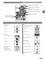
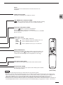
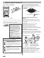
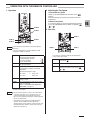
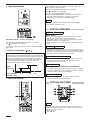
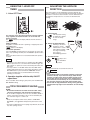
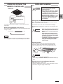
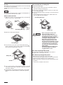
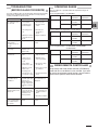
APPENDIX A Operating Instructions
CS-KS12NB41 & CZ-18BT1U + CU-KS12NK1A
CS-KS18NB4UW & CZ-18BT1U + CU-KS18NKU
CS-KS18NB4UW & CZ-18BT1U + CU-KS18NKUA
(852-6-4181-211-00-1)
A-1
Operating Instructions
Split System Air Conditioner
Model No.
Indoor Units
Outdoor Units
(For Single use)
CS-KS12NB41
CS-KS18NB4UW
CU-KS12NK1A
CU-KS18NKU
CU-KS18NKUA
(For Multiple use)
CU-3KS19NBU
CU-4KS24NBU
CU-4KS31NBU
Ceiling Panel
CZ-18BT1U
This air conditioner uses the refrigerant R410A.
“Multiple use” is applied for the model
CS-KS18NB4UW only.
• “Single use” means that only one indoor unit is
connected with one outdoor unit in a one-unit-to-oneunit configuration.
• “Multiple use” (i.e. Flexi-Multi system) means that two
or more indoor units are connected with one outdoor
unit in a multiple-unit-to-one-unit configuration.
Before operating the unit, read these operating instructions thoroughly and keep them for future reference.
Panasonic Corporation
1006 Kadoma, Kadoma City, Osaka, Japan
85264181211001
CV6233187622
FEATURES
This air conditioner is an inverter type unit that automatically adjusts capability as appropriate. Details on these functions are provided below;
refer to these descriptions when using the air conditioner.
• Microprocessor Controlled Operation
• Automatic and 3-step Fan Speed
The interior compartment of the remote controller contains
several features to facilitate automatic operation, easy
logically displayed for easy use.
• Simple One-touch Remote Controller
The remote controller has several features to facilitate
automatic operation.
• 24-Hour ON or OFF Timer
This timer can be set to automatically turn the unit on or off
at any time within a 24 hour period.
• 1-Hour OFF Timer
This timer can be set to automatically turn off the unit at
any time after one hour.
• Night Setback
This function saves energy by controlling operation to
provide a quieter operating sound than normal.
Auto/High/Medium/Low
• Air Sweep Control
This function moves a flap up and down in the air outlet,
directing air in a sweeping motion around the room and
providing comfort in every corner.
• Auto. Flap Control
This automatically sets the flap to the optimum position
during cooling and drying operation.
• Automatic Restart Function for Power Failure
Even when power failure occurs, preset programmed
operation can be reactivated once power resumes.
• High Power Operation
The unit operates at maximum output for 30 minutes,
regardless of the desired temperature.
The fan speed is 1 step above “High”.
CONTENTS
Page
Page
FEATURES.................................................................................2
PRODUCT INFORMATION ........................................................2
SAFETY PRECAUTIONS...........................................................2
INSTALLATION LOCATION........................................................3
ELECTRICAL REQUIREMENTS ...............................................3
SAFETY INSTRUCTIONS..........................................................3
NAMES OF PARTS ....................................................................4
USING THE REMOTE CONTROLLER ......................................8
OPERATION WITH THE REMOTE CONTROLLER...................9
1. Operation ....................................................................9
2. Adjusting the Fan Speed .............................................9
3. Fan Only......................................................................9
4. Night Setback Mode..................................................10
5. HIGH POWER Mode.................................................10
SPECIAL REMARKS ............................................................... 10
SETTING THE TIMER ............................................................. 10
USING THE 1-HOUR OFF TIMER .......................................... 12
TIPS FOR ENERGY SAVING .................................................. 12
ADJUSTING THE AIRFLOW DIRECTION .............................. 12
OPERATION WITHOUT THE REMOTE CONTROLLER......... 13
CARE AND CLEANING ........................................................... 13
TROUBLESHOOTING (BEFORE CALLING FOR SERVICE) . 15
OPERATING RANGE............................................................... 15
WIRED REMOTE CONTROLLER ........................................... 15
SPECIFICATIONS.................................................................... 16
PRODUCT INFORMATION
If you have problems or questions concerning your Air
Conditioner, you will need the following information. Model
and serial numbers are on the nameplate on the bottom of
the cabinet.
SAFETY PRECAUTIONS
The following symbols used in this manual, alert you
to potentially dangerous conditions to users, service
personnel or the appliance:
This symbol refers to a hazard or unsafe
practice which can result in severe
personal injury or death.
Model No. __________________________________
Serial No. ___________________________________
Date of purchase _____________________________
Dealer’s address _____________________________
Phone number _______________________________
2
CAUTION
This symbol refers to a hazard or unsafe
practice which can result in personal
injury or product or property damage.
INSTALLATION LOCATION
• We recommend that this air conditioner be installed
properly by qualified installation technicians in
accordance with the Installation Instructions
provided with the unit.
• Before installation, check that the voltage of the electric
supply in your home or office is the same as the voltage
shown on the nameplate.
• Do not install this air conditioner
where there are fumes or flammable
gases, or in an extremely humid space
such as a greenhouse.
• Do not install the air conditioner where
excessively high heat-generating
objects are placed.
• To prevent possible hazards from insulation failure,
the unit must be grounded.
• Do not clean inside the indoor and outdoor units by users.
Engage authorized dealer or specialist for cleaning.
• In case of malfunction of this appliance, do not repair by
yourself. Contact to the sales dealer or service dealer for a
repair.
• Refrigerant gas leakage may cause fire.
• For safety, be sure to turn the air conditioner off and
also to disconnect the power before cleaning.
• Pull off the power plug from a receptacle, or switch off the
breaker, or switch off the power disconnecting mean to
isolate the air conditioner from the main power supply in
case of emergency.
CAUTION
Avoid:
To protect the air conditioner from heavy corrosion, avoid installing
the outdoor unit where salty sea water can splash directly onto it or
in sulphurous air near a spa.
ELECTRICAL REQUIREMENTS
1. All wiring must conform to the local electrical codes.
Consult your dealer or a qualified electrician for details.
2. Each unit must be properly grounded with a ground (or
earth) wire or through the supply wiring.
3. Wiring must be done by a qualified electrician.
NOTE
Pull off the power plug from a receptacle, or switch off the breaker, or
switch off the power disconnecting mean to isolate the air conditioner
from the main power supply when not in use for a long time.
• Do not turn the air conditioner on and off from the power
mains switch. Use the ON/OFF operation button.
• Do not stick anything into the air outlet of the outdoor unit.
This is dangerous because the fan is rotating at high
speed.
• Do not touch the air inlet or the sharp aluminum fins
of the outdoor unit. You may get injured.
• Keep the fire alarm and the air outlet at least 1.5m away from
the unit.
• Do not let children play with the air conditioner.
• Do not cool or heat the room too much if babies or invalids
are present.
• Do not sit or step on the unit. You may fall down
accidentally.
• Do not stick any object into the FAN CASE.
You may be injured and the unit may be damaged.
SAFETY INSTRUCTIONS
• Read this Instruction Manual carefully before using
this air conditioner. If you still have any difficulties
or problems, consult your dealer for help.
• This air conditioner is designed to give you
comfortable room conditions. Use this only for its
intended purpose as described in this Instruction
Manual.
• Confirm to authorized dealer or specialist on usage of
specified refrigerant type.
Using of refrigerant other than the specified type may cause
product damage, burst and injury etc.
• Never touch the unit with wet hands.
• Never use or store gasoline or other flammable vapor or
liquid near the air conditioner — it is very dangerous.
• Do not use this appliance in a potentially explosive
atmosphere.
• This air conditioner has no ventilator for intaking fresh air
from outdoors. You must open doors or windows frequently
when you use gas or oil heating appliances in the same
room, which consume a lot of oxygen from the air.
Otherwise there is a risk of suffocation in an extreme case.
• Do not swallow the battery.
• After removing the battery from remote controller, keep it
away from the reach of children. The battery can cause
death by suffocation if swallowed.
• When inserting the battery, make sure the polarities
(+ and -) are correct.
NOTICE
• This device complies with part 15 of the FCC Rules.
Operation is subject to the following two conditions:
(1) This device may not cause harmful interference, and (2) this
device must accept any interference received, including
interference that may cause undesired operation.
• This equipment has been tested and found to comply with
the limits for a Class B digital device, pursuant to part 15 of
the FCC Rules.
These limits are designed to provide reasonable protection
against harmful interference in a residential installation. This
equipment generates, uses and can radiate radio frequency
energy and, if not installed and used in accordance with the
instructions, may cause harmful interference to radio
communications. However, there is no guarantee that
interference will not occur in a particular installation. If this
equipment does cause harmful interference to radio or television
reception, which can be determined by turning the equipment off
and on, the user is encouraged to try to correct the interference
by one or more of the following measures:
• Reorient or relocate the receiving antenna.
• Increase the separation between the equipment and receiver.
• Connect the equipment into an outlet on a circuit different from
that to which the receiver is connected.
• Consult the dealer or an experienced radio/TV technician for
help.
• FCC Caution: To assure continued compliance, follow the
attached installation instructions. Any changes or modifications
not expressly approved by the party responsible for compliance
could void the user's authority to operate this equipment.
3
NAMES OF PARTS
UNIT DISPLAY AND OPERATION
BUTTON
INDOOR UNIT
INDOOR UNIT
Air Intakes
OPERATION button
OPERATION lamp
Air Outlet!
(4 locations)
TIMER lamp
HIGH POWER lamp
REMOTE CONTROL receiver
Remote Controller
IMPORTANT
Refrigerant Tubes
OUTDOOR UNIT
Drain Hose
Avoid using radio equipment such as mobile phone near (within
4 ft. (1.2 m)) the remote control receiver. Some radio equipment
may cause malfunction of the unit.
If the trouble happens, disconnect power and restart the air
conditioner after a few minutes.
Air Outlet
REMOTE
CONTROL
receiver
This section picks up infrared signals from the
remote controller (transmitter).
OPERATION
button
When the remote controller cannot be used,
pressing this button enables cooling operation.
Each time this button is pressed, the operation
mode changes cyclically.
NOTE
Cooling operation
Stop
This illustration is based on the external view of a standard model.
Consequently, the shape may differ from that of the air conditioner
which you have selected.
This air conditioner consists of an indoor unit and an outdoor unit.
You can control the air conditioner with the remote controller.
OPERATION
lamp
This lamp lights when the system is in the
continuous DRY (orange), COOL (green) and
FAN (green) mode.
Air Intake
Air from the room is drawn into this section and
passes through air filters which remove dust.
TIMER lamp
This lamp lights when the system is being
controlled by the timer.
Air Outlet
Conditioned air is blown out of the air
conditioner through the air outlet.
HIGH POWER
lamp
This lamp lights during operation in the HIGH
POWER mode.
Remote
Controller
The remote controller controls power ON/OFF,
operation mode selection, temperature, fan
speed, timer setting, and air sweeping.
Refrigerant
Tubes
The indoor and outdoor units are connected by
copper tubes through which refrigerant gas
flows.
Drain Hose
Moisture in the room condenses and drains off
through this hose.
The outdoor unit contains the compressor, fan
Outdoor
(Condensing) motor, heat exchanger coil, and other electrical
components.
Unit
4
NOTE
The unit’s display lamps are dimmed during operation in the NIGHT
SETBACK mode.
REMOTE CONTROLLER (DISPLAY)
Displayed when transmitting data
Displayed when indoor unit sensor is
in use
Displayed when setting temperature
Displayed when temperature is shown
Displayed when setting timer
Displayed when the time
display is set to 12-hour
time.
Symbols
(1) Operation mode
(4) Timer
MILD DRY ..............................
24-hour clock with ON/OFF
program Timer .......................
COOL .....................................
ON Timer. ..............................
FAN ........................................
OFF Timer. ............................
(2) Fan speed
1-hour OFF Timer. .................
Automatic operation ...............
(5) NIGHT SETBACK..................
HIGH .....................................
MEDIUM.................................
(6) Confirmation
of transmission.......................
LOW .......................................
(7) Auto. flap indication................
(3) Temperature setting
60 – 86 °F
When set to 80 °F
temperature indication............
Flap angle indication..............
Sweep indication....................
(8) High power operation.............
5
REMOTE CONTROLLER
Transmitter
When you press the buttons on the remote controller, the
mark
appears in the display to transmit the setting changes to the receiver
in the air conditioner.
Display
Information on the operating conditions is displayed while the remote
controller is switched on. If the unit is turned off, FLAP setting and
FAN SPEED setting are not displayed.
HIGH POWER button
: If this button is pressed during DRY, COOL or FAN operation, the unit
operates at maximum output for 30 minutes, regardless of the
desired temperature.
The fan speed is 1step above ‘‘HIGH’’.
FAN SPEED selector button
: The air conditioner automatically decides the fan speeds.
: High fan speed
: Medium fan speed
: Low fan speed
FLAP button
Press this button either to select the setting of the airflow direction to the auto.
flap in each mode or one of the six possible positions manually or to select the
sweep function which moves the flap up and down automatically.
: Auto flap setting: If selected in a cooling or dry operation, the flap is set
at position (7) in the following chart.
: The airflow direction can be set manually. (six positions)
: The flap moves up and down automatically.
NOTE
When you press the FLAP button, the air flow direction will be changed one by
one as follows.
SWEEP
ON TIME/OFF TIME setting buttons
Advance button
Return button
No display: The timer does not operate.
: The air conditioner starts at the set time.
: The air conditioner stops at the set time.
: The air conditioner stops and starts, or starts and
stops, at the set times every day. For details, see
“SETTING THE TIMER”.
CANCEL button
SENSOR button
When you press this button (use a small-tipped object such as a ballpoint
pen), the
mark will appear at the display. And the room temperature is
detected by the sensor which is built into the indoor unit and the air
conditioner is controlled accordingly.
NOTE
If the remote controller is located near a heat source, such as a space
heater or in direct sunlight, press the SENSOR button to switch to the
sensor on the indoor unit.
ADDRESS switch
• The address switch changes to prevent mixing of signals from remote controller’s when
two air conditioners are installed next to each other. Normally, the address switch is set
to A. For more information, please contact the dealer where you made the purchase.
• Normally, the tabs on the remote controller should not be bent.
6
Temperature display selector button
This switches the temperature display
between °C and °F.
Sensor
A temperature sensor inside the remote controller senses the room
temperature.
ON/OFF operation button
This button is for turning the air conditioner on and off.
1 HR. TIMER button (1-HOUR OFF TIMER)
: When you press this button, regardless of whether the unit is operating
or stopping, the unit operates for one hour and then shuts down.
Temperature setting buttons (TEMP.)
Press the
button to increase the set temperature.
Press the
button to reduce the set temperature.
The temperature setting changes by 1 °C or 2 °F each time one of the TEMP.
buttons is pressed.
MODE selector button
Use this button to select DRY, COOL or FAN mode.
(DRY)
: The air conditioner reduces the humidity in the room.
(COOL)
: The air conditioner makes the room cooler.
(FAN)
: The air conditioner works only as a circulation fan.
NIGHT SETBACK button
For details, see “4. Night Setback Mode”. When you press this button in the
DRY or COOL mode, the
mark appears in the display, and the remote
controller will automatically adjust the set temperature to save energy.
CLOCK button
Time display selector button
This switches the time display between 24-hour time and 12-hour time.
ACL button (ALL CLEAR)
Puts the remote controller into pre-operation status. Always press this button
after replacing the batteries.
NOTE
(Cover closed)
• The illustration above pictures the remote controller after the cover has been opened.
• The remote controller sends the temperature signal to the air conditioner regularly at five minute intervals. If the signal from the
remote controller stops for more than 15 minutes due to the loss of the remote controller or other trouble, the air conditioner will
switch to the temperature sensor which is built into the indoor unit and control the room temperature. In these cases, the
temperature around the remote controller may differ from the temperature detected at the air conditioner’s position.
• The indoor fan runs continuously when the system is in normal operation. It does not turn off when the desired room temperature is
reached. If Night Set Back mode is selected, the fan will turn off intermittently during cooling operation in order to control air flow.
7
USING THE REMOTE CONTROLLER
HOW TO INSTALL BATTERIES
HOW TO USE THE REMOTE CONTROLLER
When using the remote controller, always point the unit’s transmitter
head directly at the air conditioner’s receiver.
Air Conditioner
(Indoor unit)
Receiver
Remote Controller
ACL button
1. Slide the cover in the direction indicated by the arrow and remove
it.
2. Install two AAA alkaline batteries. Make sure the batteries point in
the direction marked in the battery compartment.
3. Use a thin object such as the tip of a pen to press the ACL button.
CAUTION
• The batteries last about six months,
depending on how much you use the
remote controller. Replace the
batteries when the remote controller’s
display fails to light, or when the
remote controller cannot be used to
change the air conditioner’s settings.
• Use two fresh leak-proof type-AAA
alkaline batteries.
• In replacing batteries, follow the
instructions as mentioned in the
subsection “HOW TO INSTALL
BATTERIES”.
• If you do not use the remote controller
more than 1 month, take out the
batteries.
• Dispose of the used batteries at the
designated location in compliance
with the applicable local ordinances.
REMOTE CONTROLLER INSTALLATION
POSITION
The remote controller may be operated either from a non-fixed
position or from a wall-mounted position. To ensure that the air
conditioner operates correctly, do not install the remote controller in
the following places:
•
•
•
•
•
•
•
In direct sunlight
Behind a curtain or other places where it is covered
More than 26 ft.(8 m) away from the air conditioner
In the path of the air conditioner’s airstream
Where it may become extremely hot or cold
Where it may be subject to electrical or magnetic noise
Where there is an obstacle between the remote controller and air
conditioner (since a check signal is sent from the remote controller
every 5 minutes)
MOUNTING THE REMOTE CONTROLLER
Before mounting the remote controller, press the ON/OFF operation
button at the mounting location to make sure that the air conditioner
operates from that location. The indoor unit should make a beeping
sound to indicate that it has received the signal.
Rear Side
Remote Control Holder
Information for Users on Collection and Disposal
of Old Equipment and used Batteries
[Information on Disposal in other Countries
outside the European Union]
These symbols are only valid in the European Union.
If you wish to discard these items, please contact
your local authorities or dealer and ask for the correct
method of disposal.
Note for the battery symbol (bottom two symbol
examples):
This symbol might be used in combination with a
chemical symbol. In this case it complies with the
requirement set by the Directive for the chemical
involved.
Pb
8
(Transmitter
head)
Press
Set in
place
Mounting Screws
5/32 x 5/8"
(4 x 16 mm)
(included)
Hole
• To prevent loss of the remote
controller, you can connect the
remote controller to the holder by
passing a string through the remote
controller and attachment hole.
To take out the remote controller, pull it forward.
WHEN HOLDING THE REMOTE CONTROLLER
• When using the remote controller and during air conditioner
operation, the transmitter on the remote controller should be
pointed towards the receiver on the indoor unit.
• Make sure that there are no objects between the remote controller
and receiver which could block the signal.
OPERATION WITH THE REMOTE CONTROLLER
1. Operation
2. Adjusting the Fan Speed
A. Automatic fan speed
Simply set the FAN SPEED selector button to the
position.
This automatically sets the best fan speed for the room
temperature.
B. Manual fan speed
STEP 2
STEP 3
If you want to adjust fan speed manually during operation,
just set the FAN SPEED selector button as desired. [
,
, or
]
3. Fan Only
STEP 2
STEP 1
STEP 4
STEP 5
NOTE
Check that the circuit breaker on the power panel is
turned on.
STEP 3
STEP 1
Press the setting buttons as described below and
change the settings as desired.
STEP 1
STEP 2
STEP 3
Press the MODE selector button
and select the desired mode.
For dehumidifying operation
o
For cooling operation
o
For fan only operation
o
To start the air conditioner, press the ON/
OFF operation button.
Press the TEMP. setting buttons to change
the temperature setting to the desired
temperature.
Adjustable temperature range:
30 °C max.
16 °C min.
or
If you want to circulate air without any temperature
control, follow these steps:
STEP 1
Press the MODE selector button to switch to
the fan mode
.
STEP 2
Press the ON/OFF operation button.
STEP 3
Press the FAN SPEED selector button to
select the fan speed of your choice (
,
or
).
86 °F max.
60 °F min.
STEP 4
Set the FAN SPEED selector button to the
setting you want.
STEP 5
Press the FLAP button and set the airflow
direction as desired.
(Refer to “ADJUSTING THE AIRFLOW
DIRECTION” on page 12.)
To stop the air conditioner, press the ON/OFF
operation button again.
NOTE
• Choose the best position in the room for the remote
controller, which also acts as the sensor for room
comfort and transmits the operating instructions.
Once you’ve found this best position, always keep the
remote controller there.
• This appliance has a built-in 5-minute time delay
circuit to ensure reliable operation. When the
operation button is pressed, the compressor will start
running within three minutes. In the event of power
failure, the unit will stop.
9
4. Night Setback Mode
HIGH POWER mode can be used to increase the output of the
indoor unit for all operation modes.
Press the HIGH POWER button while unit is operating.
The
mark appears in the display.
To cancel, press HIGH POWER button again.
• When the HIGH POWER button is pressed, the unit operates at
maximum output for 30 minutes, regardless of the desired
temperature. The fan speed is 1 step above “High”.
NOTE
Depending on the operating conditions, the fan speed may be
increased by a small amount only.
SPECIAL REMARKS
‘‘DRY’’ (
) Operation
How it works?
Night Setback Mode is used for saving energy.
Press the NIGHT SETBACK button while unit is operating.
The
mark appears in the display.
To release the night setback function, press the NIGHT SETBACK
button again.
In Cooling and DRY Mode: (
and
)
When the night setback mode is selected, the air conditioner
automatically raises the temperature setting 2 °F when 30 minutes
have passed after the selection was made, and then another 2 °F
after another 30 minutes have passed, regardless of the indoor
temperature when night setback was selected. This enables you
to save energy without sacrificing comfort. This function is
convenient when gentle cooling is needed.
• Once the room temperature reaches the level that was set, the
unit’s operation frequency is changed automatically.
• During DRY operation, the fan speed automatically runs at lower
speed for providing a comfortable breeze.
• ‘‘DRY’’ operation is not possible if the indoor temperature is 59 °F
or less.
Cooling ( ) operation
• Sometimes the indoor unit may not get to the set fan speed such as
LOW under cool operation at very low outdoor temperatures due to
the indoor unit being protected from ice or frost when combined with
the outdoor unit for Low Ambient Cooling models.
Power failure during operation
• In the event of power failure, the unit will stop. When the power is
resumed, the unit will restart automatically in approximately
5 minutes by the remote controller.
Clicking Sound
Setting
temperature
Press the NIGHT
SETBACK button
2 °F
Clicking sound is heard from the air conditioner
• In cooling operation, any plastic parts may shrink due to a sudden
temperature change. In this event, a clicking sound may occur. This
is normal, and the sound will soon disappear.
2 °F
30 min.
5. HIGH POWER Mode
30 min.
Time
Remote Controller
• The remote controller sends the setting condition to the air
conditioner regularly at five minute intervals.
SETTING THE TIMER
NOTE
In the descriptions below, the following settings are used for the
temperature and time indicator selector button on the bottom front
section of the remote controller.
• Temperature: °F
• Time: AM, PM
10
1. How to set the present time
Operation
(Example) To set to 10:30 pm.
Indication
1. Press the ON TIME setting
button once.
2. Press the Advance, Return
( , ) button until AM 7:10
is displayed.
Operation
1. Press the CLOCK button
once if the time indicator is
not flashing.
Indication
The time indication alone
flashes.
2. Press the Advance, Return
The time can be set in 1-minute
( , ) button until PM 10:30 increments. Holding down the
is displayed.
button advances the time rapidly
in 10-minute increments.
3. Press the CLOCK button
again.
The timer
indication is
displayed, and the present ON
time is shown.
The timer
indication
blinks.
The time can be set in 10-minute
increments. Holding down the
button advances the time rapidly
in 10-minute increments.
3. Wait a few seconds, and then The timer
indication
stops blinking and the present
time is displayed.
the setting is complete.
4. How to set daily ON/OFF repeat timer
(Example) To start operation at 7:10 am. and stop the air conditioner
at 11:00 am.
This completes the setting of the
current time.
2. How to set the OFF time
(Example) To stop the air conditioner at 11:00 am.
10:30 pm.
Present time
7:10 am.
ON
Operation
Operation
1. Press the OFF TIME setting
button once.
Indication
The timer
indication is
displayed, and the present OFF
time is shown.
2. Press the Advance, Return
The timer
indication
( , ) button until AM 11:00 blinks.
is displayed.
The time can be set in 10-minute
increments. Holding down the
button advances the time rapidly
in 10-minute increments.
3. Wait a few seconds, and then The timer
the setting is complete.
indication
stops blinking and the present
time is displayed.
3. How to set the ON time
(Example) To start operation at 7:10 am.
1. Set the timer ON/OFF times
as shown in 2-1, 2, 3 and 3-1,
2, 3.
11:00 am.
OFF
Indication
The present time 10:30 pm. and
are displayed.
NOTE
• The ON/OFF combination timer uses the current time as the
reference, and it is activated starting from whichever set time
comes first.
• With the ON/OFF combination timer, the settings are repeated
every day.
• You can check the timer ON/OFF times after you have set them by
pressing the ON TIME and OFF TIME setting buttons.
To cancel a timer program
• Press the CANCEL button.
• When either an ON or OFF timer is to be canceled, press the
button corresponding to the timer whose program is to be
canceled, and then press the CANCEL button.
NOTE
• The airflow direction, fan speed and temperature setting can be
changed after a timer program has been set even when the unit is
stopped. Even when operation is stopped during an ON timer
program, the unit will start operating when the set time is reached
provided that the program is not canceled.
• When the ON timer and OFF timer are set to the same time, the
timer operates as if it is turned off.
11
USING THE 1-HOUR OFF
TIMER
1. 1-Hour OFF Timer
This function causes the unit to operate for one hour and then
stop, regardless of whether the unit is on or off when this
button is pressed.
The
indicator in the display indicates that this function is
operating.
Setting procedure:
Regardless of whether the unit is operating or stopped, press the 1
HR. TIMER button.
appears in the display.
Cancellation procedure:
Press the ON/OFF operation button to turn the unit off, wait for the
unit to stop operating, and then press the ON/OFF operation button
again.
The 1-Hour Timer function is now cancelled and the unit operates
normally.
NOTE
• If, while the 1-Hour Timer function is operating, the 1HR. TIMER
button is pressed once to cancel the function and then again, the
unit continues to operate for one hour from that point in time and
then stops.
• It is not possible to use the OFF Timer and 1-Hour OFF Timer
together. Whichever function is set last takes precedence. If the 1
HR. TIMER button is pressed while the TIMER OFF function
operates, the OFF Timer is cancelled and the unit will stop
operating one hour later.
2. Operation together with the daily ON/OFF
repeat timer
The 1-Hour OFF Timer setting is given priority over the DAILY ON/
OFF REPEAT setting.
TIPS FOR ENERGY SAVING
Avoid
• Do not block neither the air intake nor the air outlet. It may
cause less performance, and may leads to malfunctions.
• Do not let direct sunlight into the room. Use sunshades, blinds or
curtains. If the walls and ceiling of the room are warmed by the
sun, it will take longer to cool the room.
Do
• Always try to keep the air filter clean. (Refer to “CARE AND
CLEANING”.) A clogged filter will impair the performance of the
unit.
• To prevent conditioned air from escaping, keep windows, doors and
any other openings closed.
12
ADJUSTING THE AIRFLOW
DIRECTION
The vertical airflow can be adjusted by moving the flap with the
remote controller. Do not move the flap with your hands. Confirm that
the remote controller has been turned on. Use the FLAP button to
set either the sweep function or one of the six airflow direction
settings.
A. Sweep function
The flap starts moving
up and down to deliver
air over the sweep
range.
B. Setting the airflow manually
SWEEP
Referring to the above
illustration, use the
COOL
FLAP button to set the DRY
airflow direction within FAN
the range used during
the cooling or
dehumidifying operation.
C. Auto flap function
The flap is set to
the
recommended
position.
NOTE
The flap automatically closes when the unit is off.
CAUTION
• Use the FLAP button on the remote controller to adjust the
position of the flap. If you move the flap by hand, the flap
position according to the remote controller and the actual
flap position may no longer match. If this should happen,
shut off the unit, wait for the flap to close, and then turn on
the unit again; the flap position will now be normal again.
• Do not have the flap pointed down during cooling operation.
Condensation may begin to form around the air vent and drip
down.
OPERATION WITHOUT THE
REMOTE CONTROLLER
CARE AND CLEANING
• Cleaning and maintenance operations
must be carried out by specially
trained personnel.
While working in high places, slipping
or falling may result in serious injury.
• For safety, be sure to turn the air
conditioner off and also to disconnect
the power before cleaning.
• Do not pour water on the indoor unit to
clean it. This will damage the internal
components and cause an electric
shock hazard.
INDOOR UNIT
OPERATION button
OPERATION lamp
Ceiling panel (Indoor Unit)
Clean the ceiling panel of the indoor unit with a vacuum cleaner
brush, or wipe it with a clean, soft cloth.
If you have lost the remote controller or it has trouble, follow the
steps below.
When the air conditioner is not running
Each time the OPERATION button is pressed, the operation mode
changes cyclically.
Cooling operation
If it is stained, use a clean cloth moistened with a mild liquid
detergent. When cleaning it, be careful not to force the flaps out of
place.
CAUTION
Stop
NOTE
The temperature is set to the room temperature minus 4°F during
the cooling operation, and the fan speed and flap are set to Auto.
• Never use solvents, or harsh chemicals
when cleaning the indoor unit. Do not
wipe the plastic casing using very hot
water.
• Some metal edges and the fins are
sharp and may cause injury if handled
improperly; be especially careful when
you clean these parts.
• The internal coil and other components
of the outdoor unit must be cleaned
every year. Consult your dealer or
service center.
Cleaning the flaps
• The air outlet flap can be removed and washed with water.
• Be sure to always stop operation before removing the flap.
• After washing with water, allow it to dry, and then remount it.
CAUTION
• Do not move the flap with your hands.
• When using a footstool or the like, be careful not to let it tip
over.
Cleaning the main unit and Remote Controller
• Wipe clean using a soft, dry cloth.
• To remove stubborn dirt, moisten a cloth in warm water no hotter
than 104 °F, wring thoroughly, and then wipe.
13
Air filter
The air filter collects dust and other particles from the air and should
be cleaned once every 6 months.
If the filter gets blocked, the efficiency of the air conditioner drops
greatly.
How to remove the air intake grille
1. Open the air intake grille.
2. Detach the safety cord from the frame (remember to attach it
again after cleaning or maintenance).
3. Hold on the air intake grille and pull it towards you to detach the
NOTE
two air intake grille hinges.
The frequency with which the filter should be cleaned depends on
the environment in which the unit is used.
4. Clean the grille gently using a soft sponge, or the like. Then dry it
with care.
Neutral detergent may be used to remove stubborn dirt. Then
rinse thoroughly with water and dry it.
How to remove the filter
1. Slide the two latches of the air intake grille with your thumbs in the
Air intake grille hinge
direction of the arrow to open the grille.
Air intake
grille
Latch
Air intake grille hinge
Ceiling
panel
Safety cord
2. Open the air intake grille downward.
CAUTION
Air intake grille
3. Press the tabs on both sides of the air filter (indicated with
marks on the grill) to release the filter, and then, lift and pull the
filter up and out using the tabs to remove it.
• When cleaning the air filter, never
remove the safety cord. If it is
necessary to remove it for servicing
and maintenance inside, be sure to
reinstall the safety cord securely (hook
on the grille side) after the work.
• When the air intake grille has been
opened, rotating parts (such as the
fan), electrically charged areas, etc. will
be exposed in the unit’s opening. Bear
in mind the dangers that these parts
and areas pose, and proceed with the
work carefully.
• Periodically check the outdoor unit to
see if the air outlet or air intake is
clogged with dirt or soot.
Care: After a prolonged idle period
Check the indoor and outdoor unit air intakes and outlets for
blockage; if there is a blockage, remove it.
Safety cord
Air filter
4. Use a vacuum cleaner to remove light dust. If there is sticky dust
on the filter, wash the filter in lukewarm, soapy water, rinse it in
clean water, and dry it.
5. Insert the filter correctly again inside the grille, close the grille
letting the latches slide towards the outside and fix again the
latch.
14
Care: Before a prolonged idle period
•
•
•
•
Operate the fan for half a day to dry out the inside.
Disconnect the power supply and also turn off the circuit breaker.
Clean the air filter and replace it in its original position.
Outdoor unit internal components must be checked and cleaned
periodically.
Contact your local dealer for this service.
TROUBLESHOOTING
(BEFORE CALLING FOR SERVICE)
If your air conditioner does not work properly, first check the following
points before requesting service. If it still does not work properly,
contact your dealer or service center.
Trouble
Air conditioner does
not run at all.
Possible Cause
Remedy
1. Power failure.
1. Restore power.
2. Leakage circuit
breaker tripped.
2. Contact service
center.
3. Line voltage is too
low.
3. Consult your
electrician or
dealer.
4. Batteries in remote
controller have run
down.
4. Replace batteries.
OPERATION lamp
blinks and air
conditioner does not
operate.
Trouble in system.
Contact service
center.
Compressor runs but
soon stops.
Obstruction in front of
condenser coil.
(Outdoor Unit)
Remove obstruction.
Poor cooling
performance.
1. Dirty or clogged air
filter.
1. Clean air filter to
improve airflow.
2. Heat source or
many people in
room.
2. Eliminate heat
source if possible.
3. Doors and/or
windows are open.
3. Shut them to keep
the heat out.
4. Obstacle near air
intake or air
discharge port.
4. Remove it to ensure
good airflow.
5. Thermostat is set
5. Set the temperature
too high for cooling.
lower.
OPERATING RANGE
The air conditioner is operable within the temperature ranges as
listed below:
For Cooling Only Models : CU-KS18NKU
COOLING
Temperature
Indoor air
temperature
Outdoor air
temperature
Max.
95 °F DB /
71 °F WB
115 °F DB
Min.
67 °F DB /
57 °F WB
67 °F DB
For Low Ambient Cooling Models : CU-KS12NK1A, CU-KS18NKUA
COOLING
Temperature
Indoor air
temperature
Outdoor air
temperature
Max.
95 °F DB /
71 °F WB
115 °F DB
Min.
67 °F DB /
57 °F WB
0 °F DB
For Cooling Only Models : CU-3KS19NBU, CU-4KS24NBU,
CU-4KS31NBU
COOLING
Temperature
Indoor air
temperature
Outdoor air
temperature
Max.
95 °F DB /
71 °F WB
115 °F DB
Min.
67 °F DB /
57 °F WB
14 °F DB
WIRED REMOTE CONTROLLER
A separately sold wired remote controller (CZ-RD515U)
used with this air conditioner is also available. If you wish
to use the wired remote control function, you will need to
purchase the optional wired remote controller.
This is normal, and
the sound will soon
disappear.
Clicking sound is
heard from the air
conditioner.
In cooling operation,
any plastic parts may
shrink due to a
sudden temperature
change. In this event,
a clicking sound may
occur.
OPERATION lamp
lights but outdoor unit
will not run.
1. Turn off the power
The use of cellular
then restart the air
phones near the air
conditioner after a
conditioner may cause
while.
disturbance to its
normal operation.
2. Consult your dealer.
TIMER lamp blinks
(3 sec. interval) and
air conditioner does
not operate.
FLOAT SWITCH is
actived.
Contact service
center.
15
SPECIFICATIONS
• For Single use
Model No.
Power Source
Cooling Capacity
Heating Capacity
Cooling Outdoor (Hi)
Operation Operation Indoor(H/M/L)
Sound
Heating Outdoor (Hi)
Operation Indoor(H/M/L)
Unit Dimensions (H×W×D)
Net Weight
kW
BTU/h
kW
BTU/h
dB(A)
dB(A)
inch(mm)
lbs.(kg)
Indoor Unit
Outdoor Unit
CU-KS12NK1A
CS-KS12NB41
Single-phase, 115 V, 60 Hz
3.50 [ 0.90 ~ 3.50 ]
11,900 [ 3,000 ~ 11,900 ]
47
34/32/31
21-9/16×28-11/32×10-7/16
11-5/32×22-5/8×22-5/8
(548×720×265)
(283×575×575)
75.0(34.0)
35.3(16.0)
• For Single use
Model No.
Power Source
Cooling Capacity
Heating Capacity
Cooling Outdoor (Hi)
Operation Operation Indoor(H/M/L)
Sound
Heating Outdoor (Hi)
Operation Indoor(H/M/L)
Unit Dimensions (H×W×D)
Net Weight
kW
BTU/h
kW
BTU/h
dB(A)
dB(A)
inch(mm)
lbs.(kg)
Model No.
Unit Dimensions (H×W×D)
Net Weight
16
inch(mm)
lbs. (kg)
Indoor Unit
Outdoor Unit
CU-KS18NKU , CU-KS18NKUA
CS-KS18NB4UW
Single-phase, 208-230 V, 60 Hz
5.15 [ 1.20 ~ 5.15 ]
17,500 [ 4,000 ~ 17,500 ]
51
44/40/36
26-3/8×34-21/32×11-7/32
11-5/32×22-5/8×22-5/8
(670×880×285)
(283×575×575)
90.4(41.0)
35.3(16.0)
Ceiling Panel
CZ-18BT1U
1-9/16×24-19/32×24-19/32
(40×625×625)
6.0(2.7)
• For Multiple use
kW
BTU/h
kW
BTU/h
Indoor Unit
CS-KS18NB4UW
Single-phase, 208-230 V, 60 Hz
5.15
17,500
-
dB(A)
44/40/36
dB(A)
-
Model No.
Power Source
Cooling Capacity
Heating Capacity
Operation
Sound
Cooling Operation
(H/M/L)
Heating Operation
(H/M/L)
Unit Dimensions (H×W×D)
Net Weight
11-5/32×22-5/8×22-5/8
(283×575×575)
35.3(16.0)
inch(mm)
lbs.(kg)
• For Multiple use
Model No.
Power Source
Cooling Capacity
Heating Capacity
Operation Cooling Operation (Hi)
Sound
Heating Operation (Hi)
Unit Dimensions (H×W×D)
Net Weight
Outdoor Unit
CU-4KS31NBU
CU-4KS24NBU
Single-phase, 208-230 V, 60 Hz
5.50 [ 2.90 ~ 5.50 ]
7.50 [ 2.90 ~ 7.50 ]
9.00 [ 2.90 ~ 9.00 ]
kW
18,800
[
9,800
~
18,800
]
25,400
[
9,800
~
25,400
]
30,600
[ 9,800∼30,600 ]
BTU/h
kW
BTU/h
dB(A)
50
50
53
dB(A)
29-1/8×35-7/16×12-19/32 29-1/8×35-7/16×12-19/32 35-1/32×35-7/16×12-19/32
inch(mm)
(740×900×320)
(740×900×320)
(890×900×320)
lbs.(kg)
138.9(63.0)
138.9(63.0)
174.2(79.0)
CU-3KS19NBU
17