1
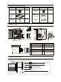
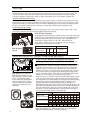
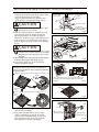
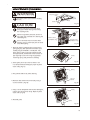
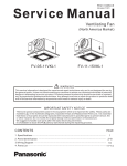
Model No.
FV-05-11VKS1
FV-05-11VK1
FV-11-15VK1
Contents
2-3
GENERAL SAFETY INFORMATION
FV-05-11VKS1
FV-05-11VK1
PLEASE READ PRIOR TO INSTALLING THIS FAN
4
DESCRIPTION
4
UNPACKING
4
SUPPLIED ACCESSORIES
5
DIMENSIONS
5
WIRING DIAGRAM
5
FEATURE
6
INDICATION (PLUG ‘N PLAY FUNCTION DEVICES)
6-7
MOTION (PLUG ‘N PLAY FUNCTION DEVICES)
7
INSTALLATION (PLUG ‘N PLAY FUNCTION DEVICES)
8
INSTALLATION (NEW CONSTRUCTION)
8-10
INSTALLATION (RETROFIT)
10
MAINTENANCE (CLEANING)
11
PRACTICAL GUIDE TO INSTALLATION
BACK COVER
SPECIFICATIONS
BACK COVER
PRODUCT SERVICE
BACK COVER
FV-11-15VK1
Thank you for purchasing this Panasonic product.
For Your Safety
To reduce the risk of injury, loss of life, electric shock, fire, malfunction, and damage to
equipment or property, always observe the following safety precautions.
Explanation of symbol word panels
The following symbol word panels are used to classify and describe the level of hazard, injury, and
property damage caused when the denotation is disregarded and improper use is performed.
WARNING
Denotes a potential hazard that could result in serious
injury or death.
CAUTION
Denotes a hazard that could result in minor injury.
The following symbols are used to classify and describe the type of instructions to be observed.
This symbol is used to alert users to a specific operating procedure that must be followed
in order to operate the unit safely.
This symbol is used to alert users to a specific operating procedure that must not be
performed.
This symbol is used to alert users not to disassemble the equipment.
This symbol is used to alert users to make sure of grounding when using the equipment
with the grounding terminal.
WARNING
To reduce the risk of fire, electric shock or injury to persons, observe the following :
Use this unit only in the manner intended by the manufacturer. If you have any questions,
contact the manufacturer.
Before servicing or cleaning unit, switch power off at service panel and lock the service
disconnecting means to prevent power from being switched on accidentally. When the
service disconnecting means cannot be locked, securely fasten a prominent warning device,
such as a tag, to the service panel.
Installation work and electrical wiring must be done by qualified person(s) in accordance with
all applicable codes and standards, including fire-rated construction.
When cutting or drilling into wall or ceiling, do not damage electrical wiring and other
hidden utilities.
Ducted fans must always be vented to the outdoors.
If this unit is to be installed over a tub or shower, it must be marked as appropriate for the
application and be connected to a GFCI(Ground Fault Circuit Interrupter) - protected branch
circuit.
These models are UL listed for tub and shower enclosures.
2
WARNING
Canada only: Not to be installed in a ceiling thermally insulated to a value greater than R40.
Do not disassemble the unit for reconstruction. It may cause fire or electric shock.
When this product is no longer being operated, please remove the product to prevent the
possibility of falling.
Ceiling joist must be subjected to static load more than five times the weight of the product.
Do not install with a method which is not approved in the instructions.
Do not use this fan with any solid-state speed control device. Solid state controls may cause
harmonic distortion which can cause motor humming noise.
This product must be properly grounded.
CAUTION
Do not install this ventilating fan where interior room temperature may
exceed 104°F(40°C).
Make sure that the electric service supply voltage is AC 120V, 60Hz.
Follow all local electrical and safety codes, as well as the National
Electrical Code (NEC) and the Occupation Safety and Health Act (OSHA).
Always disconnect the power source before working on or near the fan,
motor or junction box.
Protect the supply wiring from sharp edges, oil, grease, hot surfaces,
chemicals or other objects.
Adaptor
Do not kink the supply wiring.
Provide make up air for proper ventilation.
For general ventilating use only. Do not use to exhaust hazardous or
explosive materials and vapors.
Do not install the unit where ducts are configured as shown
in Fig.A.
Not for use in cooking area. (Fig.B)
The special-purpose or dedicated parts, such as mounting
fixtures, must be used if such parts are provided.
(Cooking area)
Do not install above or
inside this area
45
45
Cooking
equipment
Floor
Fig. B
3
PLEASE READ PRIOR TO INSTALLING THIS FAN
Spot and Continuous Ventilation: These fans are designed to run continuously ensuring a healthy
environment at low CFM levels 24 hours a day. By utilizing the optional CustomVent Multi-Speed
module the fans are built to run continuously at a pre-set lower level (FV-05-11VKS1 and FV-05-11VK1:
0, 30, 40, 50, 60, 70, 80, 90, 100 CFM; FV-11-15VK1: 0, 50, 60, 70, 80, 90, 100, 110, 120 CFM). The
setting is dependent on the size of the house and the individual wishes of the homeowner. It is crucial
that the installer pre-set the lower setting during the installation. Please refer to the chart below
and the switch indication on page 6.
CustomVent Multi-Speed module (Lower Setting). ASHRAE 62.2-2010
(sq.feet)
Two Bedrooms Three Bedrooms Four Bedrooms
<1,000
1,500
2,000
2,500
3,000
3,500
4,000
4,500
5,000
5,500
6,000
6,500
7,000
33
38
43
48
53
58
63
68
73
78
83
88
93
40
45
50
55
60
65
70
75
80
85
90
95
100
48
53
58
63
68
73
78
83
88
93
98
103
108
Five Bedrooms
55
60
65
70
75
80
85
90
95
100
105
110
These fans are also built to take care of the homeowner’s spot ventilation needs when the room is
occupied. The basic fan models allow a choice of three speeds. When fans are equipped with the optional
Multi-Speed module, these models kick up to a maximum level of 150 CFM for the FV-11-15VK1 and 110
CFM for the FV-05-11VKS1 and FV-05-11VK1 either when the switch is turned on or activated by the
optional Condensation Sensor module or the optional Motion Sensor module.
A High/Low Delay Timer, located inside the fan unit, is utilized to return the fan back to the pre-set
Continuous ventilation mode. The installer needs to consult with the homeowner for the desired
setting on the timer (0 - 60 minutes) and make the adjustments during the installation.
DESCRIPTION
These products are listed by UL under UL file No. E78414.
These products use a sirocco fan driven by a DC motor powered by an integral transformer. The motor is
designed to have long operating life, high dynamic response, higher speed ranges with saving energy.
The grille covering the fan body is a spring-loaded, quick remove type. A damper for preventing air counter
flow is provided. The blower uses a high-capacity sirocco fan developed to reduce the noise level.
UNPACKING
Unpack and carefully remove the unit from carton.
Refer to the Supplied Accessories list to verify that all parts are present.
4
SUPPLIED ACCESSORIES
Quantity
Part name
1
Warranty
sheet
1
Flex-Z FastTM
bracket
1
Tapping screw
(ST4.2X20)
4
Installation
instructions
2
Self-drilling
screw
4
Part name
Appearance
Grille
Quantity
Appearance
DIMENSIONS
Unit: inches (mm)
7/8 (22.5)
1 (26) 4 5/8 (116)
3 1/2 (88)
3 1/4 (81)
5 7/8 (148)
3 7/8 (98)
5 7/8 (148)
FV-11-15VK1
13 (330)
FV-05-11VK1
FV-11-15VK1
10 1/4 (260)
12 1/8 (307)
10
6 3/8 (163)
12
FV-11-15VK1
7 3/8 (190)
11
11
FV-05-11VKS1
No.
1
13 (330)
2
3
4
5
10 1/4 (260)
3 7/8 (100)
3 7/8 (100)
6
No.
Part name
Part name
7
Connector cover
Blade
8
Grille
Base PCB box
Motion sensor location
9
Pick-A-Flow switch
(FV-MSVK1 not included)
Junction box
Adaptor
Multi-Speed module
10
11
12
(FV-05-11VKS1 only,
other models not included)
Fan body
Damper
Flex-Z FastTM bracket
WIRING DIAGRAM
Junction box
Fan body
DC-Motor
(114°C Fuse)
Thermally
protected
Multi-Speed module
(FV-05-11VKS1
only, other models
not included)
Plug ‘N Play module slot
Switch for power
Black
Live
White
Neutral
Red
Red
(Power supply)
AC120V 60Hz
Hi/Low switch: When plug in
Multi-Speed module;
On/Off switch: When plug in
other Plug ‘N Play modules.
(Non-powered control wires)
Plug ‘N Play module slot
Green
Green
Earth ground
5
FEATURE
[For models of: FV-05-11VKS1, FV-05-11VK1, FV-11-15VK1.]
The WhisperGreen Select Line of ventilation fans employs innovative, state-of-the-art technologies that
provide a number of customizable unique features that lead to improved indoor air quality. Please
read the installation manual first in order to realize the benefits of this customizable, modular fan.
Optimum Ventilation Performance:
Duct length, elbows and other factors increase static pressure which can hinder the performance of most
ventilation fans. This fan utilizes SmartFlow microchip technology that monitors the static pressure in the
system and speeds up or slows down the rpm of the fan depending upon the amount of resistance within
the ducts. This feature allows the fan to perform as rated and avoid potential installation issues.
Outstanding Energy Savings:
The WhisperGreen Select Line of fans are built using DC motor technology. The DC motor is 30% - 70%
more energy efficient than the minimum ENERGY STAR requirements.
Pick-A-Flow
switch
All the WhisperGreen Select base models of fans come with Pick-A-Flow
speed options. The Pick-A-Flow switch on the face of all WhisperGreen
Select fans allows the option to choose 50 – 80 – 110 CFM for the
FV-05-11VK1, FV-05-11VKS1 or 110 – 130 – 150 CFM for the
FV-11-15VK1. These fans can run continuously or intermittently,
depending upon the needs of the owner.
11-15
MODEL 110130150
AIR VOLUME (CFM )
05-11 50 80 110
MODEL
Pick-A-Flow Feature
AIR VOLUME (CFM )
05-11 50 80 110
MODEL
11-15
MODEL 110130150
Air volume type (CFM)
FV-05-11VKS1
FV-05-11VK1
FV-11-15VK1
Factory setting
50
80
110
80 CFM
110
130
150
130 CFM
INDICATION (PLUG ‘N PLAY FUNCTION DEVICES)
PLUG ‘N PLAY Modular Component Accessories
Sold Separately, Not Included With Base Model Fan
11-15
MODEL 110130150
AIR VOLUME (CFM )
05-11 50 80 110
MODEL
Note that there is ONLY ONE
Plug ‘N Play slot to insert the
Multi-Speed module within the
base model fan. There are TWO
interchangeable Plug ‘N Play
slots to insert the Condensation
Sensor module, Motion Sensor
module or Nite-GloTM LED Night
Light module within the base
model fan.
FV-VS15VK1 Multi-Speed module allows the fan to run continuously
at lower speeds to maintain ventilation standards to meet Indoor
Air Quality and then boost up to high speed to meet intermittent
needs for ‘Spot’ or ‘Point Source’ exhaust needs. The FV-VS15VK1
Modular Component will operate for both the FV-05-11VK1 and the
FV-11-15VK1 matching the appropriate Multi-Speed setting shown
below. The FV-05-11VKS1 comes with the FV-VS15VK1 Multi-Speed
module. It is not necessary to purchase this component.
Note the options on the face of the FV-VS15VK1 Multi-Speed module
to choose appropriate levels of airflow (CFM) and time delay before
returning back to low speed (TIME). Choosing the Pick-A-Flow setting
automatically adjusts the Multi-Speed setting accordingly. As an
example, if the Pick-A-Flow Multi-speed setting is 80 CFM, the
Multi-Speed settings adjust automatically to be 0, 30, 40, 50, 60 or 70
CFM at the lower speeds. The fan will ‘boost’ to the 80 CFM speed as
the high speed setting. Selecting a particular TIME option will cause
the fan to run for the selected amount of time before returning to
the lower speed setting chosen on the CFM dial.
Multi-Speed Air volume (CFM)
Pick-A-Flow (CFM)
FV-05-11VKS1,
FV-05-11VK1
50
80
(plug-in FV-VS15VK1) 110
110
FV-11-15VK1
130
(plug-in FV-VS15VK1)
150
Delay Time (min)
6
0
0
0
0
0
0
30
30
30
50
50
50
40
40
40
60
60
60
40
50
50
70
70
70
40
60
60
80
80
80
40
70
70
90
90
90
40
40
40
70
70
70
80
90 100
100 100 100
100 110 110
100 110 120
45
Factory setting: 20 minutes.
Delay Time position “0“ : Manual wall switch control is 0 minute;
without manual wall switch control is 0.5 minute.
INDICATION (PLUG ‘N PLAY FUNCTION DEVICES) CONTINUED
PLUG ‘N PLAY Modular Component Accessories
Sold Separately, Not Included With Base Model Fan
FV-CSVK1 Condensation Sensor module turns the base fan on or
boosts to higher speed when humidity is detected when used in
combination with the FV-VS15VK1. The Condensation Sensor works
based on calculations from the Psychrometric Chart, or combination
of Relative Humidity (RH) and Temperature. This allows the fan to
anticipate the formation of condensation and automatically turn on
when needed to expel humid air. The Condensation Sensor is pre-set
to run for 20 minutes; it will then check the RH and Temperature to
detect if the fan needs to run for another 20 minutes cycle.
FV-MSVK1 Motion Sensor module turns the base fan on or boosts
to higher speed when motion is detected when using in combination
with the FV-VS15VK1. The Motion Sensor is pre-set to run for 20
minutes; it will then re-check for movement; if detected the fan will
run for another 20 minutes cycle. The Motion Sensor detects within
the range shown below.
The distance that motion
can be detected is limited
to 10 feet (3m). The field
of view of the sensor is 90°.
(Room temperature is 25 C).
FV-NLVK1 Nite-GloTM LED Night Light module automatically turns on
when ambient light levels are met. Turning the dial on the Modular
Nite-Glo Component to ‘DARK’ is ideal if the fan is in an isolated room
with little ambient light from nearby rooms. Turning the dial to
‘BRIGHT’ is ideal if there is light spill from nearby rooms. (Note that it is
necessary to connect wall switch when only plug in FV-NLVK1, fan can
operate on high speed with wall switch control, fan can also operate
on low speed when used in combination with the FV-VS15VK1.)
MOTION (PLUG ‘N PLAY FUNCTION DEVICES)
PLUG ‘N PLAY Modular
Components used in
Combinations
PLUG ‘N PLAY Modular Component Accessories
Sold Separately, Not Included With Base Model Fan
FV-CSVK1 + FV-MSVK1
Turns the fan on for 20 minutes when either
motion or excess humidity is detected.
FV-CSVK1 + FV-VS15VK1
Cycles the fan to high speed from low speed
for the amount of time selected on the Control
Dial based upon detection of excess humidity.
FV-MSVK1 + FV-VS15VK1
Fan
active
When motion or
At low excess humidity is
speed detected, fan runs
at high speed.
OUTSIDE
Human
active
INSIDE
Module FV-MSVK1,
FV-CSVK1 (Not
included)
Cycles the fan to high speed from low speed
for the amount of time selected on the Control
Dial based upon motion within the room.
Remains running
at high speed until
the delay time has
passed.
Motion
FV-CSVK1 only
FV-MSVK1 only
FV-CSVK1 + FV-VS15VK1
FV-MSVK1 + FV-VS15VK1
Fan
operation
Time delay
operation
Fan
ON/OFF
20 minutes
time delay
Fan
Hi/Low speed
Depend on
FV-VS15VK1 Time
delay setting
7
INSTALLATION (PLUG ‘N PLAY FUNCTION DEVICES)
You can purchase the specified Plug ‘N Play devices that are explained on page 6-7 and install them in positions
, 2 and 3 . Position
can only be used with Multi-Speed module (model FV-05-11VKS1 already have
this control installed), position 2 and 3 can be used for any of the other optional control modules.
1. Remove the connector cover from position
, 2 or 3 .
2. Plug in the specified devices to Base PCB box and fix to the slot, till hear the sound installed in place.
Connector
cover
Base PCB box
Slot
2
2
3
3
Clasp
Squeeze tabs on the Clasp to
remove. Squeeze, insert and
release the tabs on Clasp to replace.
INSTALLATION (NEW CONSTRUCTION)
The fan position between joists from 16" to 24"
on center can be adjusted flexibly.
Adaptor
Machine screw
(M4X6)
CAUTION
Please wear gloves during the installation
work as follow.
Fig.1
Fan body
1. Disconnet plug connector from receptacle and
remove adaptor from fan body by removing the
machine screw (M4X6) before installation. (Fig.1)
Joist
IMPORTANT:
Remove the tape from damper and adaptor
before installation. As shown below:
Adaptor
Bend down
4 tabs
Damper
2 Tapping screws
(ST4.2X20)
Fig.2
Tape
Joist
2. Bend down 4 tabs for positioning, install the
Flex-Z FastTM bracket to joists by using 2 tapping
screws(ST4.2X20) (Please prepare the screws and
put on Flex-Z FastTM bracket before Flex-Z FastTM
bracket is installed on joist). (Fig.2)
3. Adjust the length of Flex-Z FastTM bracket as the
spacing between joists, and install to joists by
using 2 tapping screws (ST4.2X20). (Fig.3)
4. Remove junction box cover and secure conduit
or stress relief to junction box knock-out hole.
(Fig.4)
5. Install a circular duct and secure it with clamps,
or ties and seal it with mastic or approved foil tape.
4 inch 6 inch circular duct is needed to connect to
relevant part of common adaptor. (Fig.4)
6. Install the adaptor to Flex-Z FastTM bracket by
using 2 self-drilling screws. (Fig.4)
8
2 Tapping screws
(ST4.2X20)
Fig.3
Circular duct
Conduit
Mastic or
approved
foil tape
Knock-out
hole
Junction box
cover
2 Self-drilling screws
Fig.4
INSTALLATION (NEW CONSTRUCTION) CONTINUED
7. Refer to wiring diagram on page 5.
Follow all the local electrical safety codes as well
as the National Electrical Code (NEC).
Using UL approved wire nuts, connect house
power wires to ventilating fan wires. (Fig.5)
FV-05-11VKS1
FV-05-11VK1
FV-11-15VK1
Conduit
Wire nut
Junction
box
CAUTION
Mount junction box cover carefully so that
lead wires are not pinched.
8. Insert fan body and slide into adapter assy with
some strength, untill the flange overlaps the
Flex-Z FastTM bracket. Secure the fan body to
Flex-Z FastTM bracket by using 2 self-drilling screws,
plug connector to receptacle and secure the fan
body to adaptor by using machine screw (M4X6).
(Fig.6)
Earth ground
to green
Netural to white
Two red wires
(Connect to a general
manual wall switch)
Live to black
Fig.5
Joist
CAUTION
Secure machine screw (M4X6) to the suitable
hole and not touch the Flex-Z FastTM bracket.
Please fix the screw carefully to avoid screw
slip teeth.
9. Finish ceiling work. Ceiling hole should be aligned
with the inside edge of the flange. (Fig.7)
10. Remove the tapes from louver and springs
before installation. (Fig.8)
Plug connector
Machine
screw
(M4X6)
2 Self-drilling
screws
Receptacle
)
270
Unit: inches (mm)
1/2
IMPORTANT:
Ceiling
10
/2 (
10 1
Fig.6
0)
(27
Replace the sensor cover before the installation
(only for plug-in Motion sensor modular FV-MSVK1).
As shown below:
Keep on pressing the clasps when removing the ornamental cover.
Gloves
After finishing the ceiling job, fill gap between flange
and ceillng with caulk or other sealant to prevent air
leakage
Fig.7
Ornamental
cover
Tapes
Insert the sensor cover (attachment for FV-MSVK1) into slot.
Sensor
cover
Fig.8
Clasp
Ceiling
11. Insert the grille mounting spring on the wiring
side into the slot. (Fig.9)
12. Plug in the specified devices as your choice
(refer to installation on page 8). Insert the
motion sensor (FV-MSVK1 only) or LED night
light (FV-NLVK1 only) into slot of the grille.
Fix the lead wire into the clasp (Fig.9).
Motion sensor
(FV-MSVK1 only)
LED night light
(FV-NLVK1 only)
Fig.9
9
INSTALLATION (NEW CONSTRUCTION) CONTINUED
13. Adjust Pick-A-Flow switch; if used, adjust the
FV-VS15VK1 Multi-Speed module. (Fig.10)
Refer to indication on page 6.
Ceiling
Grille
14. Insert the other mounting spring into the slot as
shown and mount grille to fan body. (Fig.11)
CAUTION
Mount grille carefully so that lead wire is
not pinched.
Fig.10
Ceiling
Mounting
spring
Gloves
Fig.11
Grille
INSTALLATION (RETROFIT)
Conduit Circular duct
WARNING
Joist
10
Disconnect power source before working
on unit.
3. Install the adaptor to Flex-Z FastTM bracket by
using 2 self-drilling screws. (Fig.13)
Fig.12
10 7/8 (275)
Circular duct
Conduit
2. Follow the step 1, 4, 5 on page 8 and step 7 on
page 9. (Before connect the circular duct to the
adaptor, should pull down the circular duct from
the ceiling)
5)
Ceiling (already existed)
(27
4 Tapping
screws (ST4.2x20)
7/8
1. Remove the existing fan and cut ceiling openning.
Secure the Flex-Z FastTM bracket to joists by using 4
tapping screws (ST4.2x20) (Please prepare the
screws and put on Flex-Z FastTM bracket before
Flex-Z FastTM bracket is installed on joist).
Existing ductwork and wiring left in place. (Fig.12)
Unit: inches (mm)
Mastic or
approved
foil tape
Joist
Knock-out
hole
Junction box
cover
2 Self-drilling screws
Ceiling
4. Secure the fan body to Flex-Z FastTM bracket by
using 2 self-drilling screws, plug connector to
receptacle and secure the fan body to adaptor
by using machine screw (M4X6). (Fig.14)
Fig.13
Joist
CAUTION
Secure machine screw (M4X6) to the suitable
hole and not touch the Flex-Z FastTM bracket.
Please fix the screw carefully to avoid screw
slip teeth.
Ceiling
Machine screw (M4X6)
Flange
2 Self-drilling screws (Fix the
flange and Flex-Z FastTM bracket through the ceiling)
5. Follow the step 10 to 14 on page 9 to 10.
10
Fig.14
WARNING
Mounting spring
Disconnect power source before working
on unit.
Grille
Gloves
Slot
Fig.15
CAUTION
Routine maintenance must be done
every year. Please wear gloves during
the cleaning work.
Never use gasoline, benzene, thinner or
any other such chemicals for cleaning the
ventilating fan.
Do not immerse motor in water when
cleaning. Do not soak resin parts in water
over 140°F (60°C).
1. Remove grille by pulling down one mounting
spring (Fig.15), then pull down the other. (For
models plug-in FV-MSVK1 or FV-NLVK1: Pull
down the mounting spring that without lead
wire passed side, and remove motion sensor or
LED night light as shown in Fig.16) (Squeeze
mounting spring and pull down carefully)
Clasp
Ceiling
Motion sensor
(FV-MSVK1 only)
LED night light
(FV-NLVK1 only)
Fig.16
Gloves
Fig.17
2. Clean grille. (Don’t put into hot water. Use
non-abrasive kitchen detergent, wipe dry with
clean cloth) (Fig.17)
Ceiling
3. The grille should be dry after cleaning.
4. Remove dust and dirt from fan body using a
vacuum cleaner. (Fig.18)
5. Using a cloth dampened with kitchen detergent,
remove any dirt from fan body. Wipe dry with
clean cloth. (Fig.19)
Vacuum
cleaner
Fig.18
Ceiling
6. Reinstall grille.
Gloves
Fig.19
11
PRACTICAL GUIDE TO INSTALLATION
Properly insulate the area around the fan to
minimize building heat loss and gain. (Fig.20)
Loose fill or batt insulation can be placed
directly over the fan housing in the attic.
Our fans and fan/light combination units do
not create excessive heat that is a common
problem with recessed light fixtures or some
competitor’s fan/light combination. Our
efficient, cool-running motors and our LED
lighting unit do not create enough ambient
heat to be subjected to these limitations.
4 inches or 6 inches roof jack, wall cap,
or soffit vent with backdraft damper
Mechanically connect duct to termination
and seal with mastic or approved foil
faced tape
2-3 ft straight run before elbow
ln attic installation,
caulk box to drywall
Short piece of flexible duct helps
alignment and absorbs sound.
Clamps plus mastic or approved
foil faced tape at all flex joints
lnsulation
Foil tape tightly covers all metal
duct joints (glue PVC joints)
Fig.20
SPECIFICATIONS
Specifications for Base Model fans
Model No.
Duct
Air
Voltage Frequency
diameter
direction
(V)
(Hz)
(inches)
FV-05-11VKS1
FV-05-11VK1
Exhaust
FV-11-15VK1
Exhaust
4 or 6
Air volume
at 0.1"WG
(CFM)
Noise
(sones)
Speed
(rpm)
Power
(W)
50
80
110
110
130
<0.3
<0.3
<0.3
<0.3
<0.3
150
<0.3
740
795
915
620
630
660
3.5
5.5
9.5
7.0
10.0
13.0
Speed
(rpm)
Power
(W)
<0.3
<0.3
<0.3
<0.3
<0.3
<0.3
<0.3
<0.3
870
835
795
760
745
740
730
725
8.0
6.5
5.5
4.3
3.6
3.5
2.7
2.4
<0.3
<0.3
<0.3
<0.3
<0.3
<0.3
<0.3
<0.3
625
620
615
610
605
600
595
590
7.4
7.0
5.6
4.9
4.4
3.8
3.6
3.1
Weight
Ib.
10.6(4.8)
10.6(4.8)
HVI Certified performance based on HVI Procedures 915, 916, and 920.
Specifications for Multi Speed fans
Model No.
Duct
Air
Voltage Frequency
diameter
direction
(V)
(Hz)
(inches)
FV-05-11VKS1,
FV-05-11VK1
(Plug-in
FV-VS15VK1)
FV-11-15VK1
(Plug-in
FV-VS15VK1)
Exhaust
Exhaust
Air volume
at 0.1"WG
(CFM)
100
90
80
70
60
50
40
30
0
120
110
100
90
80
70
60
50
0
Noise
(sones)
Weight
Ib.
10.6(4.8)
10.6(4.8)
Warning Concerning Removal of Covers. The unit should be serviced by qualified technicians only.
Your product is designed and manufactured to ensure a minimum of maintenance. Should your unit
require service or parts, call Panasonic Call Center at 1-866-292-7299 (USA) or 1-800-669-5165 (Canada).
Two Riverfront Plaza, Newark, NJ 07102
Panasonic corporation 2014
X0114-2024 15VK10420B