1
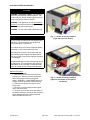
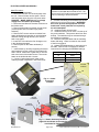
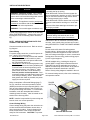
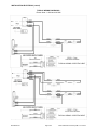
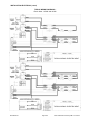
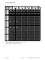
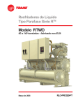
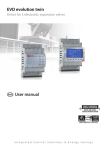
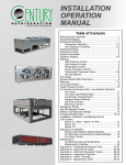
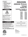
Field Electric Heater Accessory for MVA Air Handling Unit Installation, Operation and Maintenance Manual How to Use this Manual: This manual gives instructions regarding installation, operation and maintenance for the Field-installed Electric Heater Accessory for the MVA Series Air Handler. Use these instructions in conjunction with other appropriate instructions, including but not limited to those instructions supplied with the air handler and outdoor unit. Installation must comply with all applicable local codes. IMPORTANT! Refer to unit installation manual for general electrical installation and unit wiring diagrams and instructions. GENERAL Installation and maintenance are to be performed only by qualified personnel who are familiar with local codes and regulations and are experienced with HVAC equipment of this type. WARNING: Sharp edges, coil surfaces and rotating fans are a potential injury hazard – avoid contact. WARNING: Hazardous voltage – Disconnect and Lock Out all incoming power sources before servicing or installing unit. ELECTRIC SHOCK CAN CAUSE DEATH. WARNING: This equipment may be installed well above finished floor—Use extreme caution when working at heights. SAFETY WARNING: Installer should pay particular attention to the following words: NOTE–intended to clarify or make installation easier. CAUTION–given to prevent equipment damage. WARNING–to alert installer that personal injury and/or equipment damage may result if installation procedure is not properly followed. 035-000037-001 UNPACKING-CHECK FOR DAMAGE! Immediately inspect each unit for damage upon receipt. Inspect units for external and concealed damage immediately. File any damage claims in accordance with the Freight Damage Policy and Terms and Conditions. Do not repair damaged units without written authorization. Protect stored units from damage. DANGER NEVER enter an enclosed fan cabinet or reach into a unit while the fan is running. LOCK OPEN AND TAG the fan motor power disconnect switch before working on a fan. Take fuses with you and note removal on tag. Electric shock can cause personal injury or death. LOCK OPEN AND TAG the electric heat coil power disconnect switch before working on or near heaters. Failure to follow these warnings could lead to personal injury or death. Page 1 of 8 MVA Field Heater Accessory IOM 1.0 5-19-2014 ELECTRIC HEATER ACCESSORY DANGER WARNING: Hazardous voltage. Only qualified personnel must install the electrical service. Disconnect and Lock Out all incoming power sources before connecting to electrical service. WARNING: This appliance must be permanently grounded in accordance with the National Electrical Code and local code requirements. WARNING: For use with copper conductors only. Fig. 1 — Heater Accessory Installed (right side panel not shown) CAUTION Use only copper conductors for field-installed electrical wiring. Unit terminals are not designed to accept other types of conductors. Do not allow wiring to touch the refrigerant tubing, compressor, or any moving parts of the fan. Make wiring connections in accordance with the system wiring system diagram and these instructions. Wrong wiring may cause improper operation or unit damage! Unauthorized changes in the internal wiring can be very dangerous. The manufacturer will accept no responsibility for any damage or malfunction that occurs as a result of such unauthorized changes. Removal Procedure: To remove electric heater, 1. Disconnect and lock out electrical power from the unit. Remove heater access panel. Disconnect power wires from the power switch—DANGER! - MAKE SURE there is no voltage on these wires before disconnecting! 2. Disconnect 2 harness connectors at the blower deck. 3. Remove 2 screws holding heater support feet to the blower deck. 4. Remove 4 screws that mount the heater to the heater bulkhead. Handle heater carefully to avoid damaging the wire heating elements. Remove heater from the unit. 035-000037-001 Page 2 of 8 Fig. 2 — Heater Accessory Installed (right side and heater access panels not shown) MVA Field Heater Accessory IOM 1.0 5-19-2014 ELECTRIC HEATER ACCESSORY DANGER Install Procedure: To install the electric heater, 1. Disconnect and lock out electrical power from the unit. Remove heater access panel. Disconnect field power wires from the unit power wires. DANGER! - MAKE SURE there is no voltage supply to the unit before proceeding! 2. Disconnect and discard 1 harness connector at the blower deck. 3. Remove blank plate from heater access panel (covers square hole for breaker style power switches). 4. Remove SAT sensor and sensor holder from heater bulkhead and reposition on unit discharge ductwork routing through auxiliary SAT sensor hole on top panel. 5. Install SAT 3 feet after the first 90 degree turn in the discharge ductwork. 6. Remove plate on the heater bulkhead (4 screws). 7. Install heater by carefully supporting the heater and inserting it into the opening in the heater bulkhead. NOTE: Make sure to guide the pin into the hole at the back of the heater shroud. Secure the heater to the bulkhead with 4 screws. 8. Connect 2 wiring harnesses (male) to the matching female receptacles in the blower deck. WARNING: Hazardous voltage. Only qualified personnel must install the electrical service. Disconnect and Lock Out all incoming power sources before connecting to electrical service. 9. Connect field wiring to the breaker-style power switches on the front of the heater. WARNING! Be sure to provide the appropriate wire size and branch circuit protection as required by the unit nameplate! 10. Install the heater access panel. 11. Install the silicone cover “boot” over the top of the power switches. This protects them from dust buildup. The switches may be activated through the flexible boot material. 12. Mark the nameplate label with the matching heater kW rating. Label is located on the exterior of the front top panel. 13. Update EEPROM settings to values shown in the table. Refer to test run manual for detailed instructions for changing the EEPROM settings. Item Code 07 38 3C New Settings 0001 0002 -001 HEATER SHROUD PIN G RI HT SI DE Fig. 4 — Heater Accessory Installed HEATER SHROUD HEATER ASSEMBLY POWER SWITCH(ES) COVER BOOT HEATER ACCESS PANEL HEATER BULKHEAD Fig. 3 — Heater Accessory Removal (right side and heater access panels not shown for clarity) 035-000037-001 Page 3 of 8 MVA Field Heater Accessory IOM 1.0 5-19-2014 INSTALLATION-ELECTRICAL DANGER DANGER WARNING: Hazardous voltage. Only qualified personnel must install the electrical service. Disconnect and Lock Out all incoming power sources before connecting to electrical service. WARNING: This appliance must be permanently grounded in accordance with the National Electrical Code and local code requirements. WARNING: For use with copper conductors only. NEVER enter an enclosed fan cabinet or reach into a unit while the fan is running. LOCK OPEN AND TAG the fan motor power disconnect switch before working on a fan. Take fuses with you and note removal on tag. Electric shock can cause personal injury or death. LOCK OPEN AND TAG the electric heat coil power disconnect switch before working on or near heaters. Failure to follow these warnings could lead to personal injury or death. CAUTION Typical wiring diagrams are shown on the following pages FOR REFERENCE. Always refer to the wiring diagram on the air handling unit for actual wiring. Use only copper conductors for field-installed electrical wiring. Unit terminals are not designed to accept other types of conductors. malfunction of the air conditioner caused by electrical noise, route control wiring and inter-unit control wiring SEPARATELY FROM THE POWER WIRING! NOTE: CHECK MOTOR RATING PLATE FOR CORRECT LINE VOLTAGE. Connect electrical service to unit. Refer to unit wiring diagram. Power Wiring For power supply connection, route field power wiring L1 and L2 and connect either: 1. Unit Without EH: to field-provided and installed disconnect switch and from switch to power entry (unit side) and to unit power leads inside the unit electrical section; or 2. Unit With EH: into the unit through power entry (unit side) and then to the factory installed power switch inside the electrical section (part of the heater accessory—see Figure 5). Note: power switch looks like a circuit breaker but does not provide overload protection. Power switch provided only with electric heater (field kit or factory installed). NOTE: When electric heat greater than 10kW is provided, two power supply circuits are required. General Provide strain relief where field wiring passes through cabinet. Wiring within the cabinet has been positively located and supported so that it does not pass over sharp metal edges or come in contact with moving parts. After servicing, position wiring properly in the original supports. All field-installed wiring, including the electrical ground, MUST comply with the National Electrical Code (NEC) as well as applicable local codes. In addition, all field wiring must conform to the Class II temperature limitations described in the NEC. Refer to factory wiring diagrams installed in the unit. For communicating controls, refer to the condensing unit operation manual. Refer to nameplate or Electrical Ratings (page 7) for FLA, maximum overcurrent protection device (MOPD) and minimum circuit ampacity (MCA). Also refer to wiring diagram affixed to unit to make control and power wiring connections. For new heater installation, mark the nameplate label with the matching heater kW rating. Label is located on the exterior of the front top panel. POWER SWITCH NOTE: Installer is responsible for power wiring and branch circuit over current protection. Control Voltage Wiring Control voltage wiring may enter the unit at the control box located behind the blower access door, or other convenient location. Control voltage wiring leads exit the bottom of the control box and are ready for field-connection. CAUTION! To prevent 035-000037-001 Page 4 of 8 Figure 5 Unit with Electric Heat MVA Field Heater Accessory IOM 1.0 5-19-2014 INSTALLATION-ELECTRICAL (cont’d) TYPICAL WIRING DIAGRAMS— Electric Heat: 1-6kW and 8-9.5kW TYPICAL WIRING—ELECTRIC HEAT TYPICAL WIRING—ELECTRIC HEAT 035-000037-001 Page 5 of 8 MVA Field Heater Accessory IOM 1.0 5-19-2014 INSTALLATION-ELECTRICAL (cont’d) TYPICAL WIRING DIAGRAMS— Electric Heat: 14.5kW and 19.5kW TYPICAL WIRING—ELECTRIC HEAT TYPICAL WIRING—ELECTRIC HEAT 035-000037-001 Page 6 of 8 MVA Field Heater Accessory IOM 1.0 5-19-2014 UNIT ELECTRICAL RATINGS MVA Electrical Data MOTOR TOTAL FLA ELECTRIC 240HT (KW) 240 208 208V NONE 1.0 0.8 3.0 2.3 3.0 18/24 5.0 3.8 6.0 4.5 8.0 6.0 9.5 7.1 NONE 1.0 0.8 3.0 2.3 5.0 3.8 3.6 30/36 6.0 4.5 8.0 6.0 9.5 7.1 14.5 10.9 NONE 1.0 0.8 3.0 2.3 5.0 3.8 4.9 42 6.0 4.5 8.0 6.0 9.5 7.1 14.5 10.9 19.5 14.6 NONE 1.0 0.8 3.0 2.3 5.0 3.8 6.0 48 6.0 4.5 8.0 6.0 9.5 7.1 14.5 10.9 19.5 14.6 NONE 1.0 0.8 3.0 2.3 5.0 3.8 7.6 60 6.0 4.5 8.0 6.0 9.5 7.1 14.5 10.9 19.5 14.6 MVA Unit Size ELECTRIC HEAT AMPS CIRCUIT 1 240 208 NONE 4.2 3.6 12.5 10.8 20.8 18.1 25.0 21.7 33.3 28.9 39.6 34.3 NONE 4.2 3.6 12.5 10.8 20.8 18.1 25.0 21.7 33.3 28.9 39.6 34.3 39.6 34.3 NONE 4.2 3.6 12.5 10.8 20.8 18.1 25.0 21.7 33.3 28.9 39.6 34.3 39.6 34.3 39.6 34.3 NONE 4.2 3.6 12.5 10.8 20.8 18.1 25.0 21.7 33.3 28.9 39.6 34.3 39.6 34.3 39.6 34.3 NONE 4.2 3.6 12.5 10.8 20.8 18.1 25.0 21.7 33.3 28.9 39.6 34.3 39.6 34.3 39.6 34.3 CIRCUIT 2 240 208 NONE 0.0 0.0 0.0 0.0 0.0 0.0 0.0 0.0 0.0 0.0 0.0 0.0 NONE 0.0 0.0 0.0 0.0 0.0 0.0 0.0 0.0 0.0 0.0 0.0 0.0 20.8 18.1 NONE 0.0 0.0 0.0 0.0 0.0 0.0 0.0 0.0 0.0 0.0 0.0 0.0 20.8 18.1 41.7 36.1 NONE 0.0 0.0 0.0 0.0 0.0 0.0 0.0 0.0 0.0 0.0 0.0 0.0 20.8 18.1 41.7 36.1 NONE 0.0 0.0 0.0 0.0 0.0 0.0 0.0 0.0 0.0 0.0 0.0 0.0 20.8 18.1 41.7 36.1 UNIT FLA CIRCUIT 1 240 208 3.0 3.0 7.2 6.6 15.5 13.8 23.8 21.1 28.0 24.7 36.3 31.9 42.6 37.3 3.6 3.6 7.8 7.2 16.1 14.4 24.4 21.7 28.6 25.3 36.9 32.5 43.2 37.9 43.2 37.9 4.9 4.9 9.1 8.5 17.4 15.7 25.7 23.0 29.9 26.6 38.2 33.8 44.5 39.2 44.5 39.2 44.5 39.2 6.0 6.0 10.2 9.6 18.5 16.8 26.8 24.1 31.0 27.7 39.3 34.9 45.6 40.3 45.6 40.3 45.6 40.3 7.6 7.6 11.8 11.2 20.1 18.4 28.4 25.7 32.6 29.3 40.9 36.5 47.2 41.9 47.2 41.9 47.2 41.9 CIRCUIT 2 240 208 n/a n/a n/a n/a n/a n/a n/a n/a n/a n/a n/a n/a n/a n/a n/a n/a n/a n/a n/a n/a n/a n/a n/a n/a n/a n/a n/a n/a 20.8 18.1 n/a n/a n/a n/a n/a n/a n/a n/a n/a n/a n/a n/a n/a n/a 20.8 18.1 41.7 36.1 n/a n/a n/a n/a n/a n/a n/a n/a n/a n/a n/a n/a n/a n/a 20.8 18.1 41.7 36.1 n/a n/a n/a n/a n/a n/a n/a n/a n/a n/a n/a n/a n/a n/a 20.8 18.1 41.7 36.1 MINIMUM CIRCUIT AMPACITY CIRCUIT 1 CIRCUIT 2 240 208 240 208 3.8 3.8 n/a n/a 9.0 8.3 n/a n/a 19.4 17.3 n/a n/a 29.8 26.3 n/a n/a 35.0 30.8 n/a n/a 45.4 39.9 n/a n/a 53.2 46.6 n/a n/a 4.5 4.5 n/a n/a 9.7 9.0 n/a n/a 20.1 18.0 n/a n/a 30.5 27.1 n/a n/a 35.8 31.6 n/a n/a 46.2 40.6 n/a n/a 54.0 47.4 n/a n/a 54.0 47.4 26.0 22.6 6.1 6.1 n/a n/a 11.3 10.6 n/a n/a 21.8 19.7 n/a n/a 32.2 28.7 n/a n/a 37.4 33.2 n/a n/a 47.8 42.2 n/a n/a 55.6 49.0 n/a n/a 55.6 49.0 26.0 22.6 55.6 49.0 52.1 45.1 7.5 7.5 n/a n/a 12.7 12.0 n/a n/a 23.1 21.0 n/a n/a 33.5 30.1 n/a n/a 38.8 34.6 n/a n/a 49.2 43.6 n/a n/a 57.0 50.4 n/a n/a 57.0 50.4 26.0 22.6 57.0 50.4 52.1 45.1 9.5 9.5 n/a n/a 14.7 14.0 n/a n/a 25.1 23.0 n/a n/a 35.5 32.1 n/a n/a 40.8 36.6 n/a n/a 51.2 45.6 n/a n/a 59.0 52.4 n/a n/a 59.0 52.4 26.0 22.6 59.0 52.4 52.1 45.1 Maximum Overcurrent Protective Device (A) CIRCUIT 1 CIRCUIT 2 240 208 240 208 15 15 n/a n/a 15 15 n/a n/a 20 20 n/a n/a 30 30 n/a n/a 35 35 n/a n/a 50 40 n/a n/a 60 50 n/a n/a 15 15 n/a n/a 15 15 n/a n/a 25 20 n/a n/a 35 30 n/a n/a 40 35 n/a n/a 50 45 n/a n/a 60 50 n/a n/a 60 50 30 25 15 15 n/a n/a 15 15 n/a n/a 25 20 n/a n/a 35 30 n/a n/a 40 35 n/a n/a 50 45 n/a n/a 60 50 n/a n/a 60 50 30 25 60 50 60 50 15 15 n/a n/a 15 15 n/a n/a 25 25 n/a n/a 35 35 n/a n/a 40 35 n/a n/a 50 45 n/a n/a 60 60 n/a n/a 60 60 30 25 60 60 60 50 15 15 n/a n/a 15 15 n/a n/a 30 25 n/a n/a 40 35 n/a n/a 45 40 n/a n/a 60 50 n/a n/a 60 60 n/a n/a 60 60 30 25 60 60 60 50 MIN WIRE SIZE AWG* 14 14 12 10 8 8 6 14 14 10 8 8 8 6 6 14 14 10 10 8 8 6 6 6 14 14 10 10 8 8 6 6 6 14 14 10 8 8 6 6 6 6 Notes: *1. Minimum Wire Gauge is based upon Circuit 1 ampacity and the use of 75C wire at the unit. 2. 14.5kW and 19.5kW Heating units require two supply circuits. 3. MVA18/24 use ECM 5.0 motor. MVA30/36/42/48/60 use ECM-VE motor. 035-000037-001 Page 7 of 8 MVA Field Heater Accessory IOM 1.0 5-19-2014 Field Electric Heater Accessory for MVA Air Handling Unit Installation, Operation and Maintenance Manual 035-000037-001 Page 8 of 8 MVA Field Heater Accessory IOM 1.0 5-19-2014