1
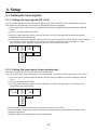
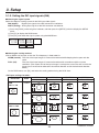
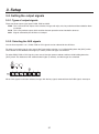
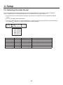
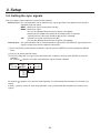
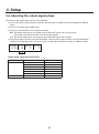
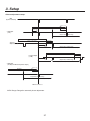
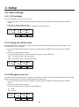
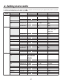
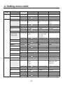
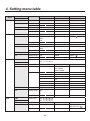
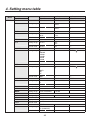
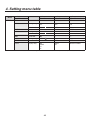
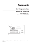
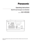
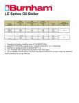
Panasonic Broadcast AV-HS300G Menu Information 3. Setup 3-1. Setting the input signals 3-1-1. Setting the input signals (IN 1 to 5) If HD has been selected as the system format, SDI or analog HD component can be selected for each input. This selection is possible only when the HD analog board has been connected. 1Press the [FUNC] switch to light its indicator, and then press the [SETUP] switch to display the SETUP menu. 2Turn [F1] to display the IN1 to 5 menu. 3Turn [F2], select the input signals using the SIG item, turn [F3], and select SDI or ANLG (analog HD component) using the MODE item. 4If analog HD component has been selected, turn [F4], and set the gain of the input signals using the GAIN item. The gain can be set within the 30-step range, and the setting will result in changes of 2 dB. The amount by which the gain changes per step is not the same for each step. IN1-5 SIG MODE GAIN 1/15 IN1 SDI IN2 ANLG -30—30 IN3 IN4 IN5 3-1-2. Setting the input signal frame synchronizer The frame synchronizer can be set to ON or OFF for each input. The input 6 (DVI input) frame synchronizer is permanently ON. It cannot be set from ON to OFF or vice versa. 1Press the [FUNC] switch to light its indicator, and then press the [SETUP] switch to display the SETUP menu. 2Turn [F1] to display the FS menu. 3Turn [F2], select the input signals using the SIG item, turn [F3], and select ON or OFF for the frame synchronizer using the FS item. '4 4*( '4 */ 0/ */ 0'' */ */ */ AVDL function is active while the frame synchronizer function is set to OFF. The AVDL function automatically adjusts the input image signal phase to the horizontal synchronization reference signal phase. For details, refer to “3-6. Adjusting the output signal phase”. 28 3. Setup 3-1-3. Setting the DVI input signals (IN6) Selecting the signal system Select the digital or analog system for the DVI input video signals. DIG (digital): Digital input signals of the DVI connector are effective. ANLG (analog): Analog input signals of the DVI connector are effective. 1Press the [FUNC] switch to light its indicator, and then press the [SETUP] switch to display the SETUP menu. 2Turn [F1] to display the DVIIN menu. 3Turn [F2], and select the signal system using the MODE item. %7**/ .0%& 4$" %*( /03. "/-( '6-Selecting the scaling method XGA or SXGA can be input as the size. The frequency is fixed at 60 Hz. NORM (normal):The size of the input images is increased or reduced while keeping their aspect ratio the same. FULL (full):The size of the input images is increased or reduced in accordance with the system resolution. (The aspect ratio of the input images is not kept the same. The rate at which the image size is increased or reduced in the vertical direction and in the horizontal direction differs.) On the DVIIN menu, turn [F3], and select the scaling method using the SCAL item. <DVI input scaling size table> DVI format XGA 1024 768 Mode HD/1080i 1920 1080 HD/720P 1280 720 NORM FULL SXGA 1280 1024 NORM FULL 29 SD/PAL*2 720 576 SD/NTSC*1 720 480 *1: 480/59.94i, *2: 576/50i 3. Setup Adjustment Adjust the clock/phase and position of the DVI input signals. 1Press the [FUNC] switch to light its indicator, and then press the [SETUP] switch to display the SETUP menu. 2Turn [F1] to display the DVIPH menu. 3Turn [F2] to adjust the clock/phase of the analog input signal using the CKPH item. Adjust this setting so that the noise will be minimum level. 4Turn [F3] to adjust the horizontal position using the HPOS item. 5Turn [F4] to adjust the vertical position using the VPOS item. %7*1) $,1) )104 7104 30 3. Setup 3-2. Setting the output signals 3-2-1. Types of output signals There are three output signal types: PGM, PVW and AUX. PGM:This is the main-line output of the switcher; images with wipe, mix, key and other effects added to them are output. PVW: This is the preview output which enables the next operation to be checked in advance. AUX: Signals selected by the AUX bus are output. 3-2-2. Selecting the AUX signals One of the crosspoints 1 to 7, PGM, PVW or CLN signals can be selected for the AUX bus. To select a crosspoint signal, press one of the B crosspoint switches 1 to 7 while holding down the [AUX] switch. The indicator of the selected switch lights (in amber), and the images are switched. To select PGM, PVW or CLN signals, press one of the wipe pattern selector switches while holding down the [AUX] switch. The indicator of the selected switch lights (in amber), and the images are switched. When CLN signals have been selected, images with the key signals removed from the PGM signals are output. 31 3. Setup 3-3. Selecting the video format One system (input/output signal) video format can be selected. More than one format cannot be selected. If HD is selected, SDI or HD analog component can be selected for each input. (See 3-1-1) 1Press the [FUNC] switch to light its indicator, and then press the [SETUP] switch to display the SETUP menu. 2Turn [F1] to display the FORMT menu. 3Turn [F2], select the format using the MODE item, and press the [F4] switch (EXEC) to enter the selection. An asterisk ( ) appears at the left of the format currently selected. '03.5 .0%& J &9&$ J Q Q J J Display 1080/59i 1080/50i 720/59p 720/50p 480/59i 576/50i HD/SD HD HD HD HD SD SD Signal format 1080/59.94i 1080/50i 720/59.94p 720/50p 480/59.94i 576/50i Input signals SDI / analog HD component SDI / analog HD component SDI / analog HD component SDI / analog HD component SDI SDI 32 3. Setup 3-4. Setting the crosspoints 3-4-1. Assigning signals to the crosspoints External video input signals and internally generated signals can be assigned to crosspoint switches 1 to 7. Displaying the assignment statuses 1Press the [FUNC] switch to light its indicator, and then press the [XPT] switch to display the XPT menu. 2The XPTAS (1/3) menu appears first, and the assignment statuses are displayed. The names of the assigned signals are abbreviated on the display. 915"4 4*( #% 915 When one of the crosspoint switches 1 to 7 is held down for a long time, the name of the signal assigned is displayed on the LCD while the button is held down. Example: When crosspoint switch 1 is pressed (when the black signal has been assigned to this switch). 915"4 4*( #-, 915 Assigning signals to the crosspoints 1Press the [FUNC] switch to light its indicator, and then press the [XPT] switch to display the XPT menu. 2Turn [F1] to display the XPTAS (2/3) menu. 3Turn [F2], select the crosspoint switch using the XPT item, turn [F3] and select the input signal using the SIG item. 915"4 915 4*( */ */ */ */ */ %7* #-, $#(% $#"3 '.&. The table below lists the materials which can be assigned. Switch XP1 to 7 Signal INPUT1 to 5 DVIIN BLACK COLOR BACKGROUND COLOR BAR FRAME MEMORY Abbreviation IN1 to 5 1 to 5 DVI D BLK B CBGD G CBAR FMEM C F 33 Description SDI or analog HD component DVI-I input Internally generated signal, black Internally generated signal, color background (matte) Internally generated signal, color bar Frame memory image 3. Setup The table below lists the default settings. Switch XP1 XP2 XP3 XP4 XP5 XP6 XP7 Signal BLACK INPUT1 INPUT2 INPUT3 INPUT4 INPUT5 DVIIN Description Internally generated signal, black External video input 1: SDI or analog HD component External video input 2: SDI or analog HD component External video input 3: SDI or analog HD component External video input 4: SDI or analog HD component External video input 5: SDI or analog HD component External video input 6: DVI-I input 3-4-2. Setting the crosspoint switching The timing at which the crosspoints are to be switched can be set. ANY: The crosspoints are switched in the nearest field. This is suited to live applications. F1: The crosspoints are switched in field 1. This is suited to editing applications. F2: The crosspoints are switched in field 2. This is suited to editing applications. 1Press the [FUNC] switch to light its indicator, and then press the [XPT] switch to display the XPT menu. 2Turn [F1] to display the XPTSW menu. 3Turn [F2], and select the switching timing using the TIMG item. 91548 5*.( "/: ' ' 34 3. Setup 3-5. Setting the sync signals The sync signals to be used by the system can be selected. External sync:For synchronization with an external sync signal (gen-lock). The reference input signal is looped through and output. BBST: Black burst signal (vertical phase of 0H) BBAD:Black burst signal This can be selected when HD format signals are supplied. (Vertical phase of 90H when the 59.94i or 59.94p format is selected; vertical phase of 75H when the 50i or 50p format is selected) TRI:Tri-level sync signal (vertical phase of 0H) This can be selected when HD format signals are supplied. Internal sync:For synchronization with an internal reference signal (INT). The REFOUT signal (black burst signal) is output from the two reference connectors. 1Press the [FUNC] switch to light its indicator, and then press the [SETUP] switch to display the SETUP menu. 2Turn [F1] to display the REF menu. 3Turn [F2], select the sync signal using the SYNC item, and press the [F4] switch (EXEC) to enter the selection. An asterisk ( ) appears at the left of the reference signal currently selected. REF SYNC GL 5/15 BBST BBAD TRI INT EXEC - An asterisk ( ) appears at the GL item when operation is synchronized with the external or internal sync signals. A dash (–) appears at the GL item when operation is not synchronized with the external or internal sync signals. 35 3. Setup 3-6. Adjusting the output signal phase The phase of the output video signals can be adjusted. 1Press the [FUNC] switch to light its indicator, and then press the [SETUP] switch to display the SETUP menu. 2Turn [F1] to display the OUPHS menu. 3Turn [F2], and select 0H or 1H using the SYS item. 0H:The output video signals are output to the system REF signal with using in-phase. The frame synchronizer function is ON for all input signals. 1H: The output video signals are output to the system REF signal with 1H delay. 4Turn [F3] to adjust H phase using the HPHS item, and turn [F4] to adjust V phase using the VPHS item. HPHS can be adjusted within a range of –0.5H to +0.5H and VPHS within a range of –100H to +100H. 061)4 4:4 )1)4 ) 71)4 ) Output video signal phase adjustment Phase HPHASE VPHASE Video format 1080i/59i 1080/50i 720/59p 720/50p 480/59i 576/50i Same for all formats Adjustment range −1100 to 1099 −1320 to 1319 −825 to 824 −990 to 989 −429 to 428 −432 to 431 −100 to 100 36 3. Setup <Phase adjustment setup> 2%& 3YSTEMSTANDARD !PPROX( !6$,2ANGE !PPROX(TO( !PPROX( )NTERNAL&IXED$, s(/UTPUT ( /UTPUT0HASE6ARIABLE2ANGE (0HASEn(TO(60HASEVERTICALLINES !6$,2ANGE )NTERNAL&IXED$, !PPROX(TO( 3HORTEST /UTPUT( !PPROX( ( /UTPUT0HASE6ARIABLE2ANGE (0HASEn(TO(60HASEVERTICALLINES !6$,2ANGE !PPROX(TO( ,ONGEST/UTPUT ( )NTERNAL&IXED$, !PPROX( ( /UTPUT0HASE6ARIABLE2ANGE (0HASEn(TO(60HASEVERTICALLINES s(/UTPUT &DELAYFOR2%&ANDINPHASEOUTPUT !PPROX( &32ANGE -!8LESSTHANAPPROXIMATELYFRAME )NTERNAL&IXED$, /UTPUT0HASE6ARIABLE2ANGE (0HASEn(TO(60HASEVERTICALLINES 2%&0HASE2EFERENCE AVDL Range: Range for automatic phase adjustment. 37 3. Setup 3-7. Network settings Set up the network for transmitting image files by Ethernet. For details on image transmission method, refer to “5. Image transmission functions”. The network initial setup is: IP address: 192.168.0.10, subnet mask: 255.255.255.0 and gateway: 0.0.0.0 (unused). When using the host computer with settings matching the network setup, it is not necessary to setup via the menu. For the setting to take effect, the system must be rebooted. Turn the system’s power off and then back on. Setting the IP address 1Press the [FUNC] switch to light its indicator, and then press the [SETUP] switch to display the SETUP menu. 2Turn [F1] to display the IP menu. 3Turn [F2] to select the setting location. An asterisk ( ) appears at the setting location. 4Turn [F3] to set the number, and press the [F3] switch to enter the setting. If the setting is not entered even though it has been changed, “ ! ” appears above the setting location, and when the setting location is moved by turning [F2], the value prior to the change is restored. *1 Setting the subnet mask 1On the SETUP menu, turn [F1] to display the MASK menu. 2Turn [F2] to select the setting location. An asterisk ( ) appears at the setting location. 3Turn [F3] to set the number, and press the [F3] switch to enter the setting. If the setting is not entered even though it has been changed, “ ! ” appears above the setting location, and when the setting location is moved by turning [F2], the value prior to the change is restored. ."4, 38 3. Setup Setting the gateway 1On the SETUP menu, turn [F1] to display the GW (Gateway) menu. 2Turn [F2] to select the setting location. An asterisk ( ) appears at the setting location. 3Turn [F3] to set the number, and press the [F3] switch to enter the setting. If the setting is not entered even though it has been changed, “ ! ” appears above the setting location, and when the setting location is moved by turning [F2], the value prior to the change is restored. (8 Setting the MAC address 1On the SETUP menu, turn [F1] to display the MAC menu. The MAC address now appears. (When the MAC address is “008045448000”.) ."$ 39 3. Setup 3-8. Other settings 3-8-1. LCD backlight The LCD backlight can be set to ON or OFF. 1Press the [FUNC] switch to light its indicator, and then press the [SETUP] switch to display the SETUP menu. 2Turn [F1] to display the SYS menu. Turn [F2], and select ON or OFF for the backlight using the BL item. 4:4 #7"/$ ## 0/ 0'' 0'' 0/ 3-8-2. Setting the ancillary data Whether the ancillary data which is superimposed on the vertical blanking period of the input images is to be passed through can be selected. 1Press the [FUNC] switch to light its indicator, and then press the [SETUP] switch to display the SETUP menu. 2Turn [F1] to display the SYS menu. Turn [F3], and select ON or OFF for the ancillary data using the VANC item. ON: The ancillary data is passed through. OFF: The ancillary data is not passed through. 4:4 #7"/$ ## 0/ 0'' 0'' 0/ 3-8-3. BB signal setup level The setup level of the BB signal in the internal sync mode can be selected. The level selected takes effect with the 59.94i or 59.94p format. It is fixed at 0 IRE with the 50i or 50p format. 1Press the [FUNC] switch to light its indicator, and then press the [SETUP] switch to display the SETUP menu. 2Turn [F1] to display the SYS menu. Turn [F4], and select the setup level using the BB item. 0: 0 IRE 7.5: 7.5 IRE 4:4 #7"/$ ## 0/ 0'' 0'' 0/ 40 3. Setup 3-9. Status displays The statuses can be displayed. 1Press the [FUNC] switch to light its indicator, and then press the [SETUP] switch to display the SETUP menu. 2Turn [F1] to display the STATS menu. ALM (alarm): Indicates a fan and/or power supply alarm. FAN Fan alarm POWR Power supply alarm F, P Fan alarm and power supply alarm NO No alarm information OPT (option): Indicates whether or not an optional board is provided. ANLG The HD analog board has been inserted. NO The HD analog board has not been inserted. VER (version): Indicates the software version. 45"54 "-. 015 7&3 '"/ "/-( 1083 /0 '1 /0 3-10. Initialization All the settings except the preset memory can be returned to the factory defaults. (When they are returned, the images in the frame memory will also be initialized.) 1Press the [FUNC] switch to light its indicator, and then press the [SETUP] switch to display the SETUP menu. 2Turn [F1] to display the INIT menu. 3Press [F2] to initialize the settings. The “INIT?” message appears. 4To initialize the settings, turn [F2] to select YES, and then press the [F2] switch. To cancel the initialization, turn [F2] to select NO, and then press the [F2] switch. */*5 */*5 &9&$ */*5 */*5 /0 :&4 41 4. Setting menu table A setting is entered when an item displayed ( ) is selected and then the [F1], [F2], [F3] or [F4] switch is pressed. (It will not be entered unless the switch is pressed.) Menu TIME WIPE Submenu Parameter 1 Turn F1 to select. Turn F2 to select. BKGD Parameter TRANSTIME Setting range 0 to 13s 1/2 Default value — Parameter TRANSTIME Setting range 0 to 13s 30f KEY 2/2 BODR 1/5 Default value — Parameter WIDT Setting range 0 to 255 30f SOFT 0 to 255 Default value Parameter Setting range Default value Parameter Setting range Default value Parameter Setting range Default value Parameter Setting range Default value Parameter Setting range 0 SAT 0 to 100 0 SAT 0 to 100 100 SAT 0 to 100 100 SAT 0 to 100 0 — — Parameter 3 Turn F4 to select. UNIT F SEC SEC UNIT F SEC SEC COLR WHT, YLW, CYN GRN, MGT, RED BLE, BLK USR1 to 4 WHT LUM 0 to 108 100 LUM 0 to 108 7 LUM 0 to 108 29 LUM 0 to 108 0 — — SAT 0 to 100 0 SAT 0 to 100 100 SAT 0 to 100 100 LUM 0 to 108 100 LUM 0 to 108 7 LUM 0 to 108 29 USR1(*) 2/5 USR2(*) 3/5 USR3(*) 4/5 USR4(*) 5/5 CBGD CBGD 1/5 USR1(*) 2/5 USR2(*) 3/5 USR3(*) 4/5 0 HUE 0 to 359 0 HUE 0 to 359 355 HUE 0 to 359 50 HUE 0 to 359 0 COLR WHT, YLW, CYN GRN, MGT, RED BLE, BLK USR1 to 4 Default value WHT Parameter HUE Setting range 0 to 359 Default value 0 Parameter HUE Setting range 0 to 359 Default value 355 Parameter HUE Setting range 0 to 359 Default value 50 42 Parameter 2 Turn F3 to select. 0 to 999f 0 to 999f 4. Setting menu table Menu CBGD KEY Submenu Turn F1 to select. USR4(*) Parameter 5/5 Setting range Default value KEY Parameter 1/7 Setting range K-ADJ 2/7 FILL 3/7 KEY-F Link from switch USR1(*) 4/7 USR2(*) 5/7 USR3(*) 6/7 USR4(*) 7/7 EDGE EDGE 1/5 USR1(*) 2/5 USR2(*) 3/5 Default value Parameter Setting range Default value Parameter Setting range Parameter 1 Turn F2 to select. HUE 0 to 359 0 TYPE SELF LIN Parameter 2 Turn F3 to select. SAT 0 to 100 0 INV ON OFF LIN CLIP 0 to 108 0 TYPE BUS COLR OFF GAIN 0 to 200 100 COLR WHT, YLW, CYN GRN, MGT, RED BLE, BLK USR1 to 4 BLE SAT 0 to 100 0 SAT 0 to 100 100 SAT 0 to 100 100 SAT 0 to 100 0 WIDT 0 to 4 Default value Parameter Setting range Default value Parameter Setting range Default value Parameter Setting range Default value Parameter Setting range Default value Parameter Setting range BUS HUE 0 to 359 0 HUE 0 to 359 355 HUE 0 to 359 50 HUE 0 to 359 0 TYPE OFF BODR DROP SHDW OUTL Default value OFF Parameter HUE Setting range 0 to 359 Default value 0 Parameter HUE Setting range 0 to 359 Default value 355 43 2 SAT 0 to 100 0 SAT 0 to 100 100 Parameter 3 Turn F4 to select. LUM 0 to 108 0 PVW ON OFF AUTO AUTO DENS 0 to 100 100 LUM 0 to 108 100 LUM 0 to 108 7 LUM 0 to 108 29 LUM 0 to 108 0 COLR WHT, YLW, CYN GRN, MGT, RED BLE, BLK USR1 to 4 YLW LUM 0 to 108 100 LUM 0 to 108 7 4. Setting menu table Menu EDGE MEM Submenu Turn F1 to select. USR3(*) Parameter 4/5 Setting range Default value USR4(*) Parameter 5/5 Setting range Default value PSMEM Parameter 1/3 Setting range PSMEM 2/3 FMEM 3/3 XPT XPTAS 1/3 XPTAS 2/3 Parameter 1 Turn F2 to select. HUE 0 to 359 50 HUE 0 to 359 0 MODE STOR RECL CLR Default value STOR Parameter XPT Setting range DSBL ENBL Default value DSBL Parameter SIG Setting range AUX Default value Display only FRZ FRZ 1/2 FRZ 2/2 1 to 10 Parameter XPT Setting range 1 to 7 Parameter 3 Turn F4 to select. LUM 0 to 108 29 LUM 0 to 108 0 EXEC ( 1 — — — — — — MEM FMEM — STOR — — SIG: B12 3 4 5D XPT: 12 3 4 5 6 7 SIG IN1 to 5, DVI BLK, CBGD, CBAR, FMEM BLK IN1 IN2 IN3 IN4 IN5 DVI — — Default value XPTSW 3/3 Parameter 2 Turn F3 to select. SAT 0 to 100 100 SAT 0 to 100 0 NO. EXEC ( ) ) — — — 1 2 3 4 5 6 7 Parameter TIMG Setting range ANY F1 F2 Default value ANY — Display only FRZ: XPT: 12 3 4 5 6 7 — — — — — — — — — Parameter SIG Setting range IN1 to 5, DVI — — FRZ Toggling between ON and OFF ( ) Default value — OFF IN1 to 5, DVI 44 — 4. Setting menu table Menu SETUP Submenu Parameter 1 Turn F1 to select. Turn F2 to select. IN1–5 Parameter SIG 1/15 Setting range IN1 to 5 Default value DVIIN 2/15 FS 3/15 FORMT 4/15 REF 5/15 IN1 to 5 Parameter MODE Setting range DIG ANLG Default value DIG Parameter SIG Setting range IN1 to 5 Default value IN1 to 5 Parameter MODE Setting range 1080/59i 1080/50i 720/59p 720/50p 480/59i 576/50i Default value 1080/59i Parameter SYNC Setting range BBST Parameter 2 Turn F3 to select. MODE SDI ANLG SDI ANLG Parameter 3 Turn F4 to select. GAIN –30 to 30 SCAL NORM FULL NORM FS ON OFF ON — — — — — GL — — — 0 — — — — — EXEC ( EXEC ( ) ) — OUPHS 6/15 Default value Parameter Setting range IP 7/15 MASK 8/15 GW 9/15 MAC 10/15 BUS 11/15 Default value Setting range Default value Setting range Default value Setting range Default value Display only Default value Parameter Setting range Default value BBAD TRI INT BBST — SYS HPHS 0H –1320 to 1319 1H 1H 0 Cursor movement 0 to 255 192.168.0.10 Cursor movement 0 to 255 255.255.255.0 Cursor movement 0 to 255 0.0.0.0 12-digit address display — MODE — A/B — P/P (PGM/PST) P/P — 45 — VPHS –100 to 100 0 — — — 4. Setting menu table Menu SETUP Submenu Parameter 1 Turn F1 to select. Turn F2 to select. SYS Parameter BL Setting range ON 12/15 OFF Default value ON DVIPH Parameter CKPH 13/15 Setting range –16 to 15 Default value 0 INIT Parameter INIT 14/15 Setting range EXEC ( ) Parameter 2 Turn F3 to select. VANC ON OFF OFF HPOS –100 to 100 0 — Parameter 3 Turn F4 to select. BB 0 7.5 7.5 VPOS –100 to 100 0 — STATS 15/15 OPT ANLG NO VER Version number Parameter Display only ALM FAN POWR F, P NO * The same USR1 to USR4 parameters are used for the WIPE menu, CBGD menu, KEY menu and EDGE menu. 46