1
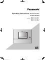
Operating Instructions <Browser Guide>
Center Module
Model No.
WX-CC411_PGQP1741ZA_BG_en.indd
1
WX-CC411
WX-CC412
2014/01/17
15:17:34
Contents
Before use .......................................................................... 3
Information display menu ............................................... 33
Preface . .......................................................................... 3
Checking the status of All-In-One Headsets
and Belt Packs .............................................................. 33
Features .......................................................................... 3
Checking the status of alerts ........................................ 33
System diagram .............................................................. 3
Troubleshooting .............................................................. 35
Operation ........................................................................ 4
Concerning the Operating Instructions ........................... 5
System requirements ...................................................... 6
Trademarks and registered trademarks .......................... 6
Abbreviations .................................................................. 6
Operating precautions....................................................... 7
Router ............................................................................. 7
Browser Refresh Rate . ................................................... 7
Browser Compatibility ..................................................... 7
Network .............................................................................. 8
Examples of connections ................................................ 8
Network Security . ........................................................... 8
Browser Operation............................................................. 9
Connecting the Center Module via a PC ........................ 9
Setup Instructions ........................................................... 9
Operation Screen . ........................................................ 10
Setup Menu . ................................................................. 10
Configuring and Confirming Settings at Installation....... 11
Confirming the group settings for All-In-One
Headsets and Belt Packs .............................................. 17
Confirming store settings .............................................. 17
Configuring and confirming settings for each lane . ...... 19
Confirming message settings ....................................... 20
Confirming the security alert settings ........................... 25
Confirming the remaining capacity and the total
capacity of the SD card . ............................................... 26
Confirming quick operation settings . ............................ 27
Backing up settings . ..................................................... 27
Performing maintenance on the Center Module ........... 28
2
WX-CC411_PGQP1741ZA_BG_en.indd
2
2014/01/17
15:17:34
Before use
wwPreface
The WX‑CC411 and WX‑CC412 are Center Modules for the wireless intercom systems that are used in drive-thru outlets.
wwFeatures
pp The WX‑CC411 is designed for single lane operation of drive-thru outlets; the WX-CC412 is designed for dual lane operation.
pp A system compliant with the 1.9 GHz band DECT* standard is used so the voices of the store personnel and customers are
heard clearly and distinctly even in open areas, and interference is minimal, resulting in stable communication.
* Digital Enhanced Cordless Telecommunications
pp A high degree of vocal clarity is ensured by a powerful echo canceller and digital noise reduction (Digital Noise Reduction).
pp The cabinet supports wall-mounting for easy installation.
pp The total number of All-In-One Headsets and Belt Packs that can be registered is 32. Up to four operators can communicate
at the same time per lane using All-In-One Headsets and Belt Packs.
pp This unit has a 7‑Type LCD display with a touch panel, and is easy to operate.
pp This unit can be connected to an IP network using Ethernet to enable remote control operations to be performed.
pp Using an SD card, it is possible to back up and restore the settings, and save messages unique to the outlet.
pp The system contains a scheduler to enable the greeter message to be changed at designated times and reminder messages
to be played back automatically.
pp Up to four Network Cameras made by Panasonic can be registered, and their images can be monitored on this unit’s LCD
display.
pp Alert signals that have been received can be sent to the All-In-One Headsets or Belt Packs, signals can be output to external
devices, and alert emails can be sent to external destinations.
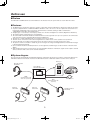
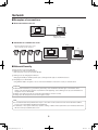
wwSystem diagram
By connecting the Center Module and All-In-One Headsets or Belt Packs wirelessly, it is possible to communicate between the
All-In-One Headsets or Belt Packs or between the All-In-One Headsets or Belt Packs and the customers at the order post.
Order post
All-In-One Headset
WX-CH450
Center Module
WX-CC411/WX-CC412
Microphone
Speaker
PAGE
(Communications with
other store personnel)
TALK
(Communications with
customers)
Belt Pack
WX-CT420
Belt Pack
WX-CT420
Vehicle detector
All-In-One Headset
WX-CH450
3
WX-CC411_PGQP1741ZA_BG_en.indd
3
2014/01/17
15:17:34
Before use
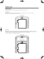
wwOperation
This system supports the following operations that are suited to drive-thru customers.
Single lane
Operations in an environment in which only one order post is installed are referred to as “single lane” operations.
These lane operations are supported by the WX‑CC411.
Hello
ORDER POST
DRIVE-THRU LANE
WINDOW
Dual lane
Operations in an environment in which the order posts are installed in parallel are referred to as “dual lane” operations.
With dual lane operations, the vehicle detectors for lane A and lane B operate independently of each other, and when each of
these vehicle detectors is set to ON, the greeter message for the lane concerned is played back.
These lane operations are supported by the WX‑CC412.
Hello
LANE B
ORDER POST
Hello
LANE A
ORDER POST
DRIVE-THRU LANE
WINDOW
LANE A
WINDOW
LANE B
4
WX-CC411_PGQP1741ZA_BG_en.indd
4
2014/01/17
15:17:34
Before use
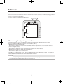
Tandem lane
Operations in an environment in which the order posts are installed in series are referred to as “tandem lane” operations. When
the vehicle detector for lane A is OFF and the vehicle detector for lane B is set to ON, a tandem lane message urging the
customer to move to lane A is played back.
These lane operations are supported by the WX‑CC412.
Pull forward
LANE A
ORDER POST
LANE B
ORDER POST
DRIVE-THRU LANE
WINDOW
LANE A
WINDOW
LANE B
wwConcerning the Operating Instructions
The Operating Instructions consist of the Operating Instructions <Installation Guide>, Operating Instructions <Setup
Instructions> (PDF file) and Operating Instructions <Browser Guide> (PDF file).
pp Operating Instructions <Installation Guide>:
These instructions describe how to connect the Center Module with the required devices, how to install them and how to
perform settings (excerpted).
pp Operating Instructions <Setup Instructions> (PDF file):
These instructions describe the settings that must be performed before this unit can be used.
pp Operating Instructions <Browser Guide> (this manual: PDF file):
These instructions explain access from the browser.
To read PDF files, you will need Adobe® Reader® which is available from Adobe Systems. When Adobe® Reader® is not installed on
the PC, download the latest Adobe® Reader® from the Adobe web site and install it.
Important
pp Download the “Operating Instructions <Setup Instructions>” from the home page given below.
http://www.panasonic.com/business/POS-drive-through/manuals.asp
5
WX-CC411_PGQP1741ZA_BG_en.indd
5
2014/01/17
15:17:35
Before use
wwSystem requirements
CPU
RAM
Network function
Operating system
Web Browser
1 GHz or faster 32-bit (x86) processor or 64-bit (x64) processor
1 GB (32-bit) or 2 GB (64-bit)
1 port 10BASE-T or 1 port 100BASE-TX
Microsoft® Windows® 7 Professional SP1 32-bit
Microsoft® Windows® 7 Professional SP1 64-bit
Microsoft® Windows® 8 Pro 32-bit
Microsoft® Windows® 8 Pro 64-bit
Microsoft® Windows® 8.1 Pro 32-bit
Microsoft® Windows® 8.1 Pro 64-bit
Microsoft® Windows® Internet Explorer 9/10
wwTrademarks and registered trademarks
pp Adobe, Acrobat Reader, and Adobe Reader are either registered trademarks or trademarks of Adobe Systems Incorporated
in the United States and/or other countries.
pp Microsoft, Windows, and Internet Explorer are either registered trademarks or trademarks of Microsoft Corporation in the
United States and/or other countries.
pp Screen shots are used in accordance with Microsoft Corporation guidelines.
pp SD, SDHC Logo is a trademark of SD‑3C, LLC.
pp Other names of companies and products contained in these operating instructions may be trademarks or registered
trademarks of their respective owners.
wwAbbreviations
The following abbreviations are used in this document.
pp Microsoft® Windows® 7 Professional SP1 64-bit, Microsoft® Windows® 7 Professional SP 32-bit, Microsoft® Windows® 8 Pro
32-bit, Microsoft® Windows® 8 Pro 64-bit, Microsoft® Windows® 8.1 Pro 32-bit and Microsoft® Windows® 8.1 Pro 64-bit are
referred to as Windows.
pp SDHC and SD memory cards are referred to as “SD cards”.
pp Universal Plug and Play is referred to as UPnP™ or UPnP.
6
WX-CC411_PGQP1741ZA_BG_en.indd
6
2014/01/17
15:17:35
Operating precautions
wwRouter
When connecting the Center Module to the Internet via a router, use a broadband router with port forwarding function (e.g. NAT,
IP masquerade).
wwBrowser Refresh Rate
The browser refresh rate may become slower depending on the network environment, computer performance and traffic.
wwBrowser Compatibility
This unit is compatible with Internet Explorer 9/10. If another browser or another version of Internet Explorer is used, the
program may not be displayed or run properly.
7
WX-CC411_PGQP1741ZA_BG_en.indd
7
2014/01/17
15:17:35
Network
wwExamples of connections
qqDirect connection to the PC
PC
Ethernet cable
(category 5, crossover)
qqConnection to a network via a hub
Hub
Panasonic Network Camera (i-pro series)
* Up to 4 cameras can be connected
PC
Ethernet cable
(category 5, straight)
wwNetwork Security
Security functions of the Center Module
1Limiting access with user authentication
Limits users who can access the Center Module.
2Limiting access by changing the HTTP port
Changing the HTTP port number prevents port scanning and other types of unauthorized access.
3Encrypting access with HTTPS
Using HTTPS enables encryption of access to the Center Module to increase the security of communications.
Important
pp Authentication information (e.g. usernames, passwords), server information and other types of information can be
leaked on the network. Take measures to prevent this from happening, such as limiting access by user authentication or
encryption of access with HTTPS.
pp Always close all browsers after accessing the Center Module to increase security.
pp Change user IDs and passwords often to strengthen security.
Note
pp If user authentication fails (authentication error) 8 or more times in 30 seconds from a PC with an identical IP address,
access to the Center Module will be blocked temporarily.
pp If 10 minutes or more passes without any operation, clicking on buttons will not perform the action intended, and instead
will return to the post-authentication screen.
8
WX-CC411_PGQP1741ZA_BG_en.indd
8
2014/01/17
15:17:35
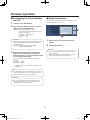
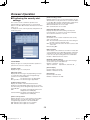
Browser Operation
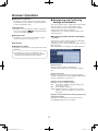
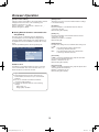
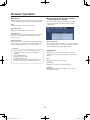
wwSetup Instructions
wwConnecting the Center Module
via a PC
This section describes basic operation procedures to set
this unit with browser operations.
1 Launch the PC’s Web browser.
2 Input the Center Module IP address into the
address bar of the Web browser.
Example) http://Center Module IP address
This unit has the following default settings as
the time of shipment:
IP address: 192.168.0.50
Port number: 80
http
Protocol:
1
2
Important
1 Input the necessary information into the
pp If the HTTP port number has changed from “80”, input
[http://Center Module IP address: port number] into
the [Address bar].
Example) If the port number is set to 8080:
http://192.168.0.50:8080
settings.
2 Click the [Set] button.
Important
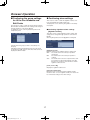
3 When a connection has been established
pp The settings will not be reflected unless the [Set]
button is clicked.
pp Do not click the button repeatedly. Doing so may
result in the settings being set incorrectly.
between the Center Module and the PC, an
authentication pop-up screen will appear. Input
the username and password.
The following are the default setting username and
password:
Username: admin
Password: 12345
pp If authentication is successful, the operation screen
will appear.
Note
pp The IP address of the Center Module can be checked
on the Center Module screen. For details, refer to the
Operating Instructions <Installation Guide>.
Important
pp Be sure to change the username and password to
ensure that the system is secure. For details, see
“Configuring server settings” (p. 13).
9
WX-CC411_PGQP1741ZA_BG_en.indd
9
2014/01/17
15:17:35
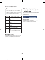
Browser Operation
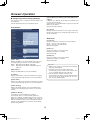
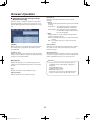
wwSetup Menu
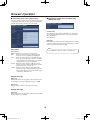
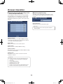
wwOperation Screen
When the [Setup] button is clicked, the menu panel displays
the Setup menu panel.
2
3
4
1
2
3
4
5
6
7
8
9
1
:
5
Menu panel
Setup menu
Displays the panel for each menu.
The menu panel displays the Setup menu and the
Information menu.
[Installation] button
This menu is used to configure and confirm settings
related to the Center Module installation. (p. 11)
[select language] pull-down menu
[Headsets] button
Changes the display language.
Languages that are available are English and French.
The screen following authentication will be displayed in
English.
This button is used to confirm the All-In-One Headsets or
Belt Packs belonging to groups 1‑6. (p. 17)
[Store] button
Setting button [Setup]
This button is used to confirm store operation-related
settings. (p. 17)
When selected, this button turns green and the menu
panel displays the Setup menu panel. (on the right)
[Lane] button
Information display button [Info]
This button is used to confirm settings for each lane. (p. 19)
When selected, this button turns green and the menu
panel displays the Information menu panel. (p. 33)
[Message] button
This button is used to confirm settings for greeter
messages, reminder messages and alert messages. The
schedule settings can be confirmed for greeter messages
and reminder messages. Sound source files to be used
for the messages can be changed or downloaded. (p. 20)
Main area
Displays the screen corresponding to the button selected.
[Security alert] button
This button is used to confirm the settings of the
operations to be performed when a security alert occurs.
(p. 25)
10
WX-CC411_PGQP1741ZA_BG_en.indd
10
2014/01/17
15:17:37
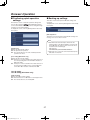
Browser Operation
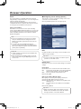
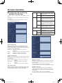
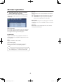
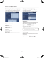
7[SD memory card] button
wwConfiguring and Confirming
Settings at Installation
This button is used to confirm the total storage capacity
and remaining storage capacity on the SD card inserted
into the Center Module. (p. 26)
This section describes how to configure and confirm settings
related to installation, such as date and time settings,
network settings, each server setting, Network Camera
settings, help contact and site information.
To display this screen, click the [Installation] button in the
Setup menu panel.
8[Quick] button
This button is used to confirm the operation settings that
were set by touching the
(Quick Operation button)
on the Center Module. (p. 27)
9[Backup] button
qqConfirming the date and time setting [Date
& time]
This button is used to back up Center Module settings
and the message voice source file. (p. 27)
This function is used to confirm the date, time and daylight
saving time settings for the Center Module.
To display this screen, click the [Installation] button, then the
[Date & time] tab.
After authentication, the following screen will be displayed.
Maintenance
:[Maintenance] button
This button is used to perform various maintenance tasks.
Important
pp The maintenance menu is for maintenance staff.
Altering settings and performing operations using the
maintenance menu may affect store operation.
[NTP/ Time zone]
Clicking on [NTP>>] displays the [Server] tab.
The NTP server settings can be configured in the [Server]
tab.
[Center module time]
Displays the current date and time of the Center Module.
The date is displayed in the format of MONTH / DAY / YEAR.
The time is displayed as a 24‑hour clock.
[Daylight saving time ON/OFF/AUTO]
Displays the setting for daylight saving time.
ON: Set the time to daylight saving time. (Advance the
current time by 1 hour)
OFF: Cancel daylight saving time.
AUTO: Daylight saving time is set based on the set date
and time to start and end (Month, week, day of the
week, time).
[Daylight saving time Start date & time], [Daylight saving
time End date & time]
Displays the start date and time and end date and time
when Daylight Saving time is set to AUTO.
11
WX-CC411_PGQP1741ZA_BG_en.indd
11
2014/01/17
15:17:37
Browser Operation
[Primary DNS server address], [Secondary DNS server
address]
If “DNS” is set to “Manual”, the IP address of the DNS server
must be entered manually.
Inquire with the system administrator for questions about the
DNS server IP address.
Default setting: None (blank)
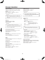
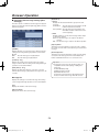
qqConfiguring network settings [Network]
This function is used to configure the network settings of the
Center Module.
Click the [Installation] button, then the [Network] tab.
IPv4 Network
[Line speed]
Displays the network transmission rate setting of the Center
Module. This setting can be changed through operations on
the Center Module.
Web server
[Connection]
Select the method for connecting to the Center Module.
HTTP: Can only connect by HTTP.
HTTPS: Can only connect by HTTPS.
Default setting: HTTP
[HTTP port]
Set the port number to be used in HTTP.
Settable port numbers: 1 to 65535
Default setting: 80
[HTTPS port]
Set the port number to be used in HTTPS.
Settable port numbers: 1 to 65535
Default setting: 443
[DHCP / Static]
Displays the DHCP of the Center Module. This setting can
be changed through operations on the Center Module.
DHCP: Operating with the DHCP setting ON.
Static:Operating with the DHCP setting OFF (static IP
address).
Important
pp If Web server settings are altered, the Center Module
will restart automatically.
pp If HTTPS is selected, the Center Module will
automatically generate an SSL server certificate. This
is only compatible with SSL self-certification.
pp The following port numbers cannot be used.
(Excluding the port number set in the default settings.)
20, 21, 23, 25, 42, 53, 67, 68, 69, 80, 110, 123, 161,
162, 443, 995, 10669, 10670
[MAC address]
Displays the MAC address of the Center Module.
[IP address]
Displays the IP address of the Center Module. This setting
can be changed through operations on the Center Module.
[Subnet mask]
Displays the subnet mask of the Center Module. This setting
can be changed through operations on the Center Module.
[Default gateway]
Displays the default gateway of the Center Module. This
setting can be changed through operations on the Center
Module.
[DNS Auto / Manual]
Set whether to retrieve the DNS server address
automatically (“Auto”) or input it manually (“Manual”).
When set to “Manual”, the DNS setting must be configured.
When using the DHCP function, if “DNS” is set to “Auto”, the
DNS server address will be retrieved automatically. Inquire
with the system administrator for questions about settings.
Default setting: Manual
12
WX-CC411_PGQP1741ZA_BG_en.indd
12
2014/01/17
15:17:38
Browser Operation
UPnP
qqConfiguring server settings [Server]
The Center Module is compatible with UPnP (Universal
Plug and Play). Using UPnP function, you can configure the
following settings automatically.
Set the router port forwarding function. (A router that is
compatible with UPnP is required.) This setting is useful for
accessing the Center Module via the Internet.
This function is used to configure the settings of the server
connected to the Center Module.
Click the [Installation] button, then the [Server] tab.
[Auto port forwarding]
Set whether or not to use the router’s port forwarding
function with the ON and OFF radio buttons. To use the auto
port forwarding function, the router being used must be the
UPnP compatible and UPnP function must be enabled.
Default setting: OFF
Note
pp Auto port forwarding may change the port number.
If the port number has been changed, the Center
Module port number registered to the PC must also
be changed.
pp To check if auto port forwarding has been set
correctly, click the [Status] tab of the [Maintenance]
button in the Setup menu panel and confirm that the
[UPnP] status is [Enabled].
NTP
Important
Configure the NTP server settings, such as the NTP server
address and port number.
pp If UPnP settings are altered, the Center Module will
restart automatically.
pp When changing port forwarding settings, check the
status of the router using the Operating Instructions
for the router.
Important
pp If a more accurate time setting is needed for system
operation, use the NTP server.
[Default] button
This button is used to restore the NTP settings to the default
settings.
[Time adjust]
Set whether or not to retrieve the time from the NTP server.
ON:Synchronize with the NTP server and automatically
adjust the date and time of the Center Module.
Do not synchronize with the NTP server.
OFF:
Default setting: OFF
[NTP server address (Manual / Auto)]
When [ON] is selected for [Time adjust], a method for
retrieving the NTP address must be selected.
Manual:Input the NTP server address into the [NTP server
address] to set.
Auto:Retrieve the NTP server address from the DHCP
server.
Default setting: Manual
Important
pp When retrieving the “NTP server address” from the
DHCP server, the DHCP function must be enabled
through operations on the Center Module.
13
WX-CC411_PGQP1741ZA_BG_en.indd
13
2014/01/17
15:17:38
Browser Operation
[SMTP server port]
Input the port number for sending email.
Settable port numbers: 1 to 65535
Default setting: 25
[NTP server address]
If “Manual” is selected for [NTP server address (Manual
/ Auto)], enter the NTP server IP address or host name
manually.
Number of characters: 1 to 128
Types of characters:alphanumeric, characters -.
Default setting: None (blank)
Important
pp The following port numbers cannot be used.
(Excluding the port number set in the default settings.)
20, 21, 23, 25, 42, 53, 67, 68, 69, 80, 110, 123, 161,
162, 443, 995, 10669, 10670
Important
pp When entering the host name into the “NTP server
address”, the DNS setting must be configured on the
[Network] tab of the [Installation] button on the Setup
menu panel.
[Authentication]
pp Type
Select one of the following authentication methods for
sending email.
No authentication
None: POP before SMTP:
Authenticate the POP servers for
receiving email before sending email.
Authenticate the SMTP server.
SMTP: Default setting: None
[NTP port]
Input the NTP server port number.
Settable port numbers: 1 to 65535
Default setting: 123
Important
pp The following port numbers cannot be used.
(Excluding the port number set in the default settings.)
20, 21, 23, 25, 42, 53, 67, 68, 69, 80, 110, 123, 161,
162, 443, 995, 10669, 10670
Note
pp If unsure of which authentication type to use for
sending email, inquire with the system administrator.
[Time adjustment interval time]
Select the interval for retrieving the time from the NTP
server (1 hour units, from 1 to 24 hours).
Default setting: 1h
pp User name
Input the username for accessing the server.
Number of characters: 0 to 32
Types of characters:alphanumeric, characters
!#$%'()=˜¦`{}<>?_-^[]/@*,.+
Default setting: None (blank)
[Time zone]
Select the time zone corresponding to the region in which
this unit is being used.
Default setting: GMT-06:00 Central Standard Time
pp User password
Input the password for accessing the server.
Number of characters: 0 to 32
Types of characters:alphanumeric, characters
!#$%'()=˜¦`{}<>?_-^[]/@*,.:;+¥
Default setting: None (blank)
SMTP
Configure the settings of the email server for sending emails
from the Center Module.
[POP3 server address]
If [POP before SMTP] is selected for [Authentication Type],
input the POP3 server IP address or host name manually.
Number of characters: 1 to 128
Types of characters:alphanumeric, characters -.
Default setting: None (blank)
[Default] button
This button is used to restore the SMTP settings to the
default settings.
[SMTP server address]
Input the IP address or host name of the SMTP server for
sending email.
Number of characters: 1 to 128
Types of characters:alphanumeric, characters -.
Default setting: None (blank)
14
WX-CC411_PGQP1741ZA_BG_en.indd
14
2014/01/17
15:17:38
Browser Operation
[Delete] button
This button is used to restore the Network Camera settings
to the default settings.
[Sender’s E-mail address]
Input the sender’s email address. The email address entered
will appear in the “From” line on the email being sent.
Number of characters: 3 to 128
Types of characters:alphanumeric, characters @ . _ ‑
Default setting: None (blank)
[IP address]
Input the IP address of the Network Cameras that are
connected to the unit.
Default setting: None (blank)
qqSetting Network Cameras connected to the
unit [Camera]
[HTTP port]
Input the port number of the Network Cameras that are
connected to the unit.
Settable port numbers: 1 to 65535
Default setting: 80
This tab is used to set Network Cameras displayed on
the LCD display of the Center Module. Setting Network
Cameras enables camera images from vehicle detectors to
be displayed on the Center Module in tandem with security
alerts.
Click the [Installation] button, then the [Camera] tab.
[Authentication]
Configure this setting if the user authentication setting is set
to “ON”.
ON:User authentication will be required when
connecting to Network Cameras.
OFF:User authentication will not be required when
connecting to Network Cameras.
[User name]
If [ON] is selected for [Authentication], input the username
for accessing the Network Cameras.
Number of characters: 0 to 32
Default setting: None (blank)
Camera 1 to 4
[User password]
If [ON] is selected for [Authentication], input the password for
accessing the Network Cameras.
Number of characters: 0 to 32
Default setting: None (blank)
A maximum of four Network Cameras can be connected
to the Center Module. This section describes how to set
Network Cameras connected to the unit.
Important
pp Network Cameras that can be connected to the
Center Module are Panasonic i-pro series Network
Cameras.
pp Be sure to set HTTP for the Network Camera
connection method setting.
pp Configure the Network Cameras to the following
settings:
· Aspect ratio: 4:3
· Image quality: standard
15
WX-CC411_PGQP1741ZA_BG_en.indd
15
2014/01/17
15:17:38
Browser Operation
qqSetting Help contact [Help contact]
Substitute
characters
This tab is used to check the telephone number and
configure the email transmission settings for the Help
contact screen displayed on the LCD display of the Center
Module.
Click the [Installation] button, then the [Help contact] tab.
Character string after substitution
%d%
Help contact email sent date
e.g. 05
%M%
Help contact email sent month (alphabetical
character)
e.g. Feb
%m%
Help contact email sent month (numerical
character)
e.g. 02
%Y%
Help contact email sent year (four-digit)
e.g. 2014
%y%
Help contact email sent year (the last two digits)
e.g. 14
%t%
Help contact email sent time
e.g. 15:00:00
%i%
IP address of the Center Module
%s%
Information entered in Site information
Important
[Telephone]
This field displays the telephone number. This setting can be
changed through operations on the Center Module unit.
pp When using the Help contact email function, confirm
that emails can be sent correctly in advance when the
unit is installed.
Configuring Help contact email transmission
settings
qqSetting Site information [Site info.]
This area is used to configure the email to be sent from the
LCD display Help contact screen.
This tab is used to input information particular to the store
in which the unit is installed, such as the contact number for
the store and management information. This information is
used when viewing store information from a browser. This
information can only be set and viewed with a browser.
Click the [Installation] button, then the [Site info.] tab.
Number of characters: 0 to 200
[Destination E-mail address]
Set the destination email addresses. The same message
can be sent to up to 5 email addresses.
Number of characters: 3 to 128
Types of characters:alphanumeric, characters @ . _ ‑
[E-mail subject]
Input the subject of the email.
Number of characters: 0 to 50
[E-mail body]
Input the body of the email.
Number of characters: 0 to 200
Note
pp The SMTP server must be set before an email can be
sent. To set the SMTP server, click the [Installation]
button, then the [Server] tab.
pp The following substitute characters can be used in the
email body. The substitute characters will be replaced
with the corresponding character string when the
email is sent.
16
WX-CC411_PGQP1741ZA_BG_en.indd
16
2014/01/17
15:17:39
Browser Operation
wwConfirming store settings
wwConfirming the group settings
for All-In-One Headsets and
Belt Packs
This screen is used to confirm the nighttime volume, store
hours and tandem lanes (WX-CC412 only).
To display this screen, click the [Store] button in the Setup
menu panel.
This function is used to confirm the group settings for All-InOne Headsets and Belt Packs. This setting can be changed
through operations on the Center Module.
To display this screen, click the [Headsets] button in the
Setup menu panel.
qqConfirming nighttime volume settings
[Nighttime volume]
This tab is used to confirm nighttime volume settings. This
setting can be changed through operations on the Center
Module.
Click the [Store] button, then the [Nighttime volume] tab.
Click the tab of the group you wish to view (Group 1 to
Group 6).
All-In-One Headsets and Belt Packs that are in the group
are displayed as “ON” in green, while those that are not are
displayed as “OFF” in black.
[Nighttime volume]
Displays whether or not nighttime volume is being used.
OFF: The volume level of the order post speaker is
unchanged.
ON: The volume level of the order post speaker is
reduced.
Auto: The volume level of the voice output from the order
post speaker is reduced automatically every day,
based on the set time to start and time to end the
nighttime volume function.
[Level (-20 to 0 dB)]
Displays the nighttime volume level.
[Start time / Ending time]
Displays the time to start and end the nighttime volume
function. If “Auto” is set for nighttime volume, the volume will
be controlled according to these time settings.
17
WX-CC411_PGQP1741ZA_BG_en.indd
17
2014/01/17
15:17:39
Browser Operation
qqConfirming tandem lanes [Tandem lane]
(WX‑CC412 only)
qqConfirming store hours [Store hours]
This tab is used to confirm store hours settings. This setting
can be changed through operations on the Center Module.
Click the [Store] button, then the [Store hours] tab.
[Tandem lane]
This tab displays the settings for tandem lanes. This setting
can be changed through operations on the Center Module.
ON: Tandem lane
OFF: Dual lane
[Message]
Displays the greeter message that is played from the Lane B
order post speaker when the Lane A vehicle detector is OFF
and the Lane B vehicle detector is ON.
Note
Store hours
pp See “Operation” (p. 4) for details on tandem lanes.
[Store hours]
Displays whether or not store hours is being used.
OFF: When the vehicle detector is ON, the greeter
message set in the scheduler is played back.
Auto: When the vehicle detector is ON within business
hours, the greeter message set in the scheduler
is played back. If it is outside business hours, the
closing greeter message is played back.
Closed: When the vehicle detector is ON, the closing
greeter message is always played back. Use this
function if the lane is closed, etc.
Holiday: When the vehicle detector is ON, the holiday
greeter message is always played back. Use this
function when playing a special greeter message
on Christmas, Halloween, etc.
Closed message
[Message]
Displays the greeter message that is played when the store
is closed (the store hours settings are Closed or AUTO).
[Day hours]
Displays the store hours for each day of the week.
Holiday message
[Message]
Displays the greeter message that is played when the [Store
hours] setting is set to Holiday.
18
WX-CC411_PGQP1741ZA_BG_en.indd
18
2014/01/17
15:17:40
Browser Operation
wwConfiguring and confirming
settings for each lane
Outside mic ON/OFF
This tab is used to configure and confirm settings for each
lane.
To display this screen, click the [Lane] button in the Setup
menu panel.
To configure and confirm settings for Lane B, click the
[Lane B] tab. (WX‑CC412 only)
Headsets
Displays whether or not the voice of the
order post microphone will be output to
the kitchen speaker.
Volume
Displays the volume of the order post
microphone output to the kitchen speaker.
TALK
Displays whether or not the [TALK]
voice from the All-In-One Headsets or
Belt Packs will be output to the kitchen
speaker.
PAGE
Displays whether or not the [PAGE]
voice from the All-In-One Headsets or
Belt Packs will be output to the kitchen
speaker.
Volume
Displays the volume of the voice from
the All-In-One Headsets or Belt Packs to
be output to the kitchen speaker.
AUX mic (ON/OFF)
Displays whether or not the voice of the
kitchen microphone will be output to the
kitchen speaker.
Beep
ON/OFF
Displays whether or not the beep tone
will be output to the kitchen speaker.
Volume
Displays the volume of the beep tone
output to the kitchen speaker.
[Input volume (0-20)]
Displays the input volume for each All-In-One Headset
and Belt Pack and the order post speaker. The volume
range is from 0 to 20. This setting can be changed through
operations on the Center Module.
Outside mic: Displays the volume of the order post
microphone.
Aux mic: Displays the volume of the kitchen microphone.
Line in: Displays the volume of the line input.
Beep: Displays the volume of the beep tone.
[Output volume (0-20)]
Displays each output volume. The volume range is from 0 to
20. This setting can be changed through operations on the
Center Module.
Outside speaker: Displays the volume of the order post
speaker.
Aux speaker: Displays the volume of the kitchen
speaker.
Line out: Displays the volume of the line output.
[Device for Line in]
Displays the output destination for line input. Line input will
be output to all All-In-One Headsets or Belt Packs and the
kitchen speaker.
You can change the output device for [LINE IN].
For details, contact the store where you purchased this unit.
[Aux speaker (0-20)]
Displays the input sound source file and the volume of the
file to be output to the kitchen speaker. This setting can be
changed through operations on the Center Module.
[Source for Line out]
Displays the input sound file source for line output. The
output destination for the line sound source file will be the
same as that of the sound source file output from the order
post speaker.
You can change the audio source for [LINE OUT].
For details, contact the store where you purchased this unit.
19
WX-CC411_PGQP1741ZA_BG_en.indd
19
2014/01/17
15:17:41
Browser Operation
[DSP]
This section displays the settings for the three functions
involved in voice signal processing (echo canceller, digital
noise reduction and ASLC).
Echo Canceller: Displays the echo suppression level. (OFF/
LOW/MID/HIGH)
Digital noise reduction:
Displays the noise suppression level. (OFF/
LOW/MID/HIGH)
ASLC: Displays whether or not Auto Speaker
Level Control is being used.
wwConfirming message settings
This section is used to confirm the settings for each type of
message and the schedule for messages.
To display this screen, click the [Message] button in the
Setup menu panel.
qqConfirming greeter message settings
[Greeter message]
This tab is used to confirm the settings of the greeter
message played when the vehicle detector is ON. This
setting can be changed through operations on the Center
Module. Click the [Message] button, then the [Greeter
message] tab.
[V/Det camera]
Images from Network Cameras can be displayed on the
Center Module LCD display in tandem with the vehicle
detector. Select the Network Camera(s) to be displayed on
the LCD display.
OFF: The Network Camera(s) are not coupled to
the vehicle detector.
Camera 1/2/3/4: When the vehicle detector is ON, the
Network Cameras are displayed on the
LCD display in tandem with the vehicle
detector.
Default setting: OFF
Note
pp Be sure to set a camera that is connected in advance
when outputting the NW camera image. To set a
camera that is connected, click the [Installation] button
in the Setup menu panel, then the [Camera] tab.
[ON/OFF]
Displays whether or not greeter message is being used.
OFF: The greeter message is not played back.
ON: The greeter message is played back.
[Volume (0 - 20)]
Displays the volume of the greeter message.
The volume range is from 0 to 20.
[Delay time (0 - 10s)]
Displays the time delay before playing the greeter message
when the vehicle detector is ON. The range is 0 to 10
seconds.
[Destination]
Displays broadcast destinations other than the order post
speaker from which the greeter message will be played.
pp All headsets
OFF: The greeter message is not broadcast to any All-InOne Headset or Belt Pack.
ON: The greeter message is broadcast to all All-In-One
Headsets or Belt Packs.
pp AUX speaker
OFF: The greeter message is not broadcast to the
kitchen speaker.
ON: The greeter message is broadcast to the kitchen
speaker.
20
WX-CC411_PGQP1741ZA_BG_en.indd
20
2014/01/17
15:17:41
Browser Operation
qqConfirming greeter message schedule
settings [Greeter schedule]
Message list
Displays the settings for each greeter message. This setting
can be changed through operations on the Center Module.
This tab is used to confirm greeter message schedule
settings. Click the [Message] button, then the [Greeter
schedule] tab.
[No.]
Displays the number of the greeter message.
[Message name]
Displays the name of the greeter message.
[Upload] button
This button is used to upload a sound source file to replace
the sound source file that is currently being used as the
greeter message.
[Download] button
This button is used to download the sound source file being
used as the greeter message from the Center Module. The
button is disabled when there is no sound source file.
[Days of the week]
The schedule for the selected day of the week is displayed.
The schedule displays the start time for playing the greeter
message and the message that will be played.
Important
Schedule list
pp Sound source files are in the following format. Use
compatible software when playing or editing files
using a PC.
Format: ADPCM (G.726)
Sampling frequency: 8 kHz
Quantization bit rate: 4 bit
Sound source files that can be uploaded must be in
the above format and no longer than 20 seconds.
Displays the greeter message start times in a list. This
setting can be changed through operations on the Center
Module.
[No.]
Displays the number of the schedule.
[Start time]
Displays the start time of the greeter message.
[Message]
Displays the message number and name of the greeter
message that will start.
21
WX-CC411_PGQP1741ZA_BG_en.indd
21
2014/01/17
15:17:42
Browser Operation
[Destination]
Displays the broadcast destinations for the reminder
message.
pp Group
Displays the broadcast destination group for the reminder
message.
All Headsets: The reminder message is broadcast to
all All-In-One Headsets or Belt Packs.
Group number:The reminder message is broadcast to
the All-In-One Headsets or Belt Packs in
the selected group(s).
pp AUX
Displays whether or not the reminder message will be
output to the kitchen speaker.
OFF: The reminder message is not output to the kitchen
speaker.
ON: The reminder message is output to the kitchen
speaker.
qqConfirming reminder message settings
[Reminder message]
This tab is used to confirm the reminder message that is
played at fixed times to urge the store personnel to work.
Click the [Message] button, then the [Reminder message]
tab.
[ON/OFF]
Displays whether or not reminder message is being used.
This setting can be changed through operations on the
Center Module.
[Upload] button
This button is used to upload a sound source file to replace
the sound source file that is currently being used as the
reminder message.
[Volume (0 - 20)]
Displays the volume of the reminder message. The volume
range is from 0 to 20. This setting can be changed through
operations on the Center Module.
[Download] button
This button is used to download the sound source file being
used as the reminder message from the Center Module. The
button is disabled when there is no sound source file.
Important
Message list
pp Sound source files are in the following format. Use
compatible software when playing or editing files
using a PC.
Format: ADPCM (G.726)
Sampling frequency: 8 kHz
Quantization bit rate: 4 bit
Sound source files that can be uploaded must be in
the above format and no longer than 20 seconds.
Displays the settings for each reminder message. This
setting can be changed through operations on the Center
Module.
[No.]
Displays the number of the reminder message.
[Message name]
Displays the name of the reminder message.
22
WX-CC411_PGQP1741ZA_BG_en.indd
22
2014/01/17
15:17:42
Browser Operation
[Interval]
Displays whether or not to repeat playback of the reminder
message.
OFF: The reminder message is played back only 1 time, at
the Start Time.
ON: The reminder message is played back repeatedly at
fixed intervals, beginning from the Start Time.
qqConfirming reminder message schedule
settings [Reminder schedule]
This tab is used to confirm reminder message schedule
settings. Click the [Message] button, then the [Reminder
schedule] tab.
[Interval time]
Displays the repeating interval for playing back the reminder
message. You can set this from 00:00 to 23:59 in increments
of 1 minute.
[Message]
Displays the message number and name of the reminder
message that will be played.
[Days of the week]
The schedule for the selected day of the week is displayed.
The schedule displays the time to play back the reminder
message and the message that will be played.
Schedule list
Displays the reminder message playback schedules in a
list. This setting can be changed through operations on the
Center Module.
[No.]
Displays the number of the schedule.
[Start – Ending time]
Displays the start time for playing back the reminder
message and the time to stop repeating playback.
Note
pp The ending time is only displayed when the Interval is
ON. It is displayed as “- -” when the Interval is OFF.
23
WX-CC411_PGQP1741ZA_BG_en.indd
23
2014/01/17
15:17:42
Browser Operation
[Destination]
pp Group
Displays the broadcast destination group for the alert
message.
All Headsets: The alert message is broadcast to all AllIn-One Headsets or Belt Packs.
Group number: The alert message is broadcast to the
All-In-One Headsets or Belt Packs in the
selected group(s).
pp AUX
Displays whether or not the alert message will be output
to the kitchen speaker.
OFF: The alert message is not output to the kitchen
speaker.
ON: The alert message is output to the kitchen speaker.
qqConfirming alert message settings [Alert
message]
This tab is used to confirm the alert message to be played
during a security alert. Click the [Message] button, then the
[Alert message] tab.
[Upload] button
This button is used to upload a sound source file to replace
the sound source file that is currently being used as the alert
message.
[ON/OFF]
Displays whether or not alert message is being used. This
setting can be changed through operations on the Center
Module.
OFF: The alert message is not played back.
ON: The alert message is played back.
[Download] button
This button is used to download the sound source file being
used as the alert message from the Center Module. The
button is disabled when there is no sound source file.
[Volume (0 - 20)]
Displays the volume of the alert message. The volume
range is from 0 to 20. This setting can be changed through
operations on the Center Module.
Important
pp Sound source files are in the following format. Use
compatible software when playing or editing files
using a PC.
Format: ADPCM (G.726)
Sampling frequency: 8 kHz
Quantization bit rate: 4 bit
Sound source files that can be uploaded must be in
the above format and no longer than 20 seconds.
[Delay time (0 - 10s)]
Displays the delay time after the occurrence of an alert
until the alert message is played back. The range is 0 to 10
seconds.
Message list
Displays the settings for each alert message. This setting
can be changed through operations on the Center Module.
[No.]
Displays the number of the alert message.
[Message name]
Displays the name of the alert message.
24
WX-CC411_PGQP1741ZA_BG_en.indd
24
2014/01/17
15:17:43
Browser Operation
[Audio recording] column
Displays whether or not to record communications onto the
SD card when a security alert notice is received from button
F of an All-In-One Headset or Belt Pack. This setting can be
changed through operations on the Center Module.
OFF: Communications are not recorded.
ON: Communications are recorded.
wwConfirming the security alert
settings
This screen is used to confirm the operations to be
performed when a security alert notice is received from
button F of an All-In-One Headset or Belt Pack or from alert
inputs 1 to 4.
To display this screen, click the [Security alert] button in the
Setup menu panel.
[Alert input delay time] column
Displays the delay time until sounding a security alert
from alert inputs 1 to 4. Can be set from 0 to 29 minutes
59 seconds in increments of 1 second.
[E-mail] column
Set whether or not to send an e-mail when each security
alert occurs and ends.
ON: An e-mail will be sent based on the e-mail settings for
the alert occurrence and end of alert.
OFF:An e-mail will not be sent for the alert occurrence and
end of alert.
Default setting: OFF
Mail for F button
Set the details of the e-mail to be sent when a security alert
occurs from button F of an All-In-One Headset or Belt Pack
and when the alert ends. This is enabled when an e-mail
is set to be sent upon receiving button F of an All-In-One
Headset or Belt Pack in the list of alerts.
[Destination E-mail address]
Set the destination email addresses. The same message
can be sent to up to 5 email addresses.
Number of characters: 3 to 128
Types of characters:alphanumeric, characters @ . _ ‑
List of alerts
Displays the types of security alerts and the operations to
perform in the event of a security alert.
[E-mail subject]
Input the subject of the email.
Number of characters: 0 to 50
[Trigger] column
Displays the types of security alerts.
[Message] column
Displays the alert message to be played during each type
of security alert. This setting can be changed through
operations on the Center Module.
OFF: The alert message is not played back.
Message number:The alert message is played back.
[E-mail body]
Input the body of the email.
Number of characters: 0 to 200
[Camera monitor] column
Displays the number of the Network Camera that is
displayed on the LCD display during each type of security
alert. This setting can be changed through operations on the
Center Module.
OFF: The image of the Network Camera is not
displayed on the LCD display.
Camera number:The image of the Network Camera is
displayed on the LCD display.
[Device control] column
Displays whether or not to control external control outputs
during each type of security alert. This setting can be
changed through operations on the Center Module.
OFF: External control outputs are not controlled.
ON: External control outputs are controlled.
25
WX-CC411_PGQP1741ZA_BG_en.indd
25
2014/01/17
15:17:43
Browser Operation
Note
wwConfirming the remaining
capacity and the total capacity
of the SD card
pp The SMTP server must be set before an email can be
sent. To set the SMTP server, click the [Installation]
button, then the [Server] tab.
pp The following substitute characters can be used in the
email body. The substitute characters will be replaced
with the corresponding character string when the
email is sent.
Substitute
characters
This tab is used to confirm the total capacity and remaining
capacity on an SD card inserted into the Center Module.
To display this screen, click the [SD memory card] button in
the Setup menu panel.
Character string after substitution
%d%
Date of alert
e.g. 05
%M%
Month of alert (alphabetical character)
e.g. Feb
%m%
Month of alert (numerical character)
e.g. 02
%Y%
Year of alert (four-digit)
e.g. 2014
%y%
Year of alert (the last two digits)
e.g. 14
%t%
Time of alert
e.g. 15:00:00
%a%
Status of alert
When an alert starts: Alert Happened
When an alert ends: Alert Stopped
%p%
Origin of alert
Alert terminal: Alert Input* (* is the terminal
number)
All-In-One Headsets and Belt Packs: “Headset”
%i%
IP address of the Center Module
%s%
Information entered in Site Information
[Remaining capacity]
Displays the remaining capacity of the SD card. Displayed
as “Remaining capacity / Total capacity”.
If there is no SD card inserted, this field displays
“--------KB/--------KB”.
Mail for Alert * (*: 1 to 4)
Set the details of the e-mail to be sent when a security alert
occurs from an alert input and when the alert ends. For
setting details see, “Mail for F button”.
26
WX-CC411_PGQP1741ZA_BG_en.indd
26
2014/01/17
15:17:43
Browser Operation
wwBacking up settings
wwConfirming quick operation
settings
This tab is used to back up Center Module settings and
messages.
To display this screen, click the [Backup] button in the Setup
menu panel.
This button is used to confirm the operation settings that
were set by touching the
(Quick Operation button)
on the Center Module. This setting can be changed through
operations on the Center Module.
To display this screen, click the [Quick] button in the Setup
menu panel.
[Execute] button
This button is used to back up Center Module settings and
message voice source files to the PC.
Note
pp Data that has been backed up is extracted to the
following folder on the SD card. When restored on the
Center Module, the settings can be restored to those
used at the time of backing up.
SD card route:
\PRIVATE\PANA_GRP\PSN\DWCS\BACKUP
pp Message voice source files cannot be backed up if an
SD card is not inserted.
[Speed team]
Displays the Speed team settings.
OFF: No Speed team operation.
ON: The vehicle detectors are shut off and Speed team
operation is in effect.
[Cross beep] (WX-CC412 only)
Displays the Cross beep settings.
OFF: A beep tone is only heard when the vehicle detector of
the corresponding lane for the All-In-One Headset or
Belt Pack is ON.
ON: A beep tone is also heard when the vehicle detector of
the other lanes in addition to the corresponding lane
for the All-In-One Headset or Belt Pack are ON.
Lane A setting
Lane B setting (WX‑CC412 only)
[V/Det override]
Displays the V/Det override settings.
OFF: Vehicle detectors turn ON when a vehicle approaches.
ON: The vehicle detectors are virtually ON.
27
WX-CC411_PGQP1741ZA_BG_en.indd
27
2014/01/17
15:17:44
Browser Operation
wwPerforming maintenance on the
Center Module
This screen is used to check the status of and perform
maintenance on each device. The maintenance menu is for
maintenance staff.
To display this screen, click the [Maintenance] button in the
Setup menu panel.
qqChecking the Center Module [Status]
This tab displays the status of the Center Module DECT ID,
MAC address and UPnP.
Click the [Maintenance] button, then the [Status] tab.
[DECT ID]
Displays the DECT ID of the Center Module.
[MAC address]
Displays the MAC address of the Center Module.
UPnP
[HTTP]
Displays the information for an HTTP connection.
pp [Port number]
Displays the port number set for port forwarding in UPnP.
pp [Status]
Displays the port forwarding status. Displays “-” during an
HTTPS connection.
[HTTPS]
Displays the information for an HTTPS connection.
pp [Port number]
Displays the port number set for port forwarding in UPnP.
pp [Status]
Displays the port forwarding status. Displays “-” during an
HTTP connection.
[Router global address]
Displays the global address of the router.
28
WX-CC411_PGQP1741ZA_BG_en.indd
28
2014/01/17
15:17:44
Browser Operation
Important
pp Check the [HTTP Status] / [HTTPS Status] after 10 minutes have passed since starting up the router and Center Module.
pp The following chart shows the meaning and action to take for each port forwarding [HTTP Status] / [HTTPS Status].
Message
Meaning
Action
— (no message)
Connected without port forwarding.
To change the connection type, click the [Installation] button,
then the [Network] tab and set the connection type.
Disabled
Internet publishing has not been set up
for a Center Module that is using the
router UPnP function.
Click the [Installation] button, then the [Network] tab and set
“Auto port forwarding” to “ON” in “UPnP”.
Enabled
Internet publishing has been set up
properly for a Center Module that is
using the router UPnP function.
—
Setting
Automatic port forwarding is being set
up for a Center Module that is using the
router UPnP function.
Wait for the router to finish setting up.
Deleting
After disabling automatic port
forwarding for a Center Module that
is using the router UPnP function, the
UPnP settings of the router are being
deleted.
The router is not UPnP compatible, or
the UPnP function has not been set.
Wait for the system to finish deleting the router UPnP settings.
Failed to set
Failed to delete
After changing to a setting where
Internet publishing is not set for a
Center Module that is using the router
UPnP function, the system failed to
delete the UPnP settings of the router.
pp The UPnP function of the router has been disabled.
Refer to the instruction manual for the router to enable the
UPnP function.
pp The router does not have a UPnP function.
Set port forwarding according to the instruction manual for the
router.
pp The power for the router has been turned off.
Turn on the power for the router, then restart the Center
Module.
pp If the network status for the Center Module reads “Static”,
the network settings are incorrect.
Confirm the default gateway and subnet mask settings for the
Center Module network.
pp Some routers may not work with the Center Module, even
if they are UPnP compatible and have been enabled,
because they are not compatible with the Center Module. In
such cases, set port forwarding according to the instruction
manual for the router.
[Reboot]
Clicking the [Reboot] button restarts the Center Module.
Important
pp When the Center Module is rebooted from a browser, the Center Module will restart without displaying a warning on the
LCD display. Be sure to check the operational status before rebooting from a browser.
29
WX-CC411_PGQP1741ZA_BG_en.indd
29
2014/01/17
15:17:44
Browser Operation
qqRetrieving log data [Log]
qqRetrieving TALK & PAGE Recording sound
source files [Recorded data]
This tab is used to download the operational log of the
Center Module. Click the [Maintenance] button, then the
[Log] tab.
This tab displays sound source files from TALK & PAGE
Recording that were recorded during a security alert by
holding down button F of an All-In-One Headset or Belt
Pack. Click the [Maintenance] button, then the [Recorded
data] tab.
[Download] button
This button is used to download the log file.
Important
pp Note that Panasonic cannot respond to inquiries
about log data.
[Delete] checkbox
Selects the checkboxes of all TALK & PAGE Recording
sound source files. Delete the sound source files that are
selected by clicking the [Delete] button.
[File] column
Displays the filename of the sound source file.
[Lane] column
Displays the lane for TALK & PAGE Recording.
[Download] button
This button is used to download a TALK & PAGE Recording
file from the Center Module.
[Delete] button
This button is used to delete sound source files with
checkboxes selected.
Important
pp Sound source files are in the following format. Use
compatible software when playing or editing files
using a PC.
Format: ADPCM (G.726)
Sampling frequency: 8 kHz
Quantization bit rate: 4 bit
Sound source files that can be uploaded must be in
the above format and no longer than 20 seconds.
30
WX-CC411_PGQP1741ZA_BG_en.indd
30
2014/01/17
15:17:45
Browser Operation
qqConfirming the software version [Update]
qqSetting authentication [User mng.]
This tab is used to confirm the software version. Software
version updates can also be performed from this screen.
Click the [Maintenance] button, then the [Update] tab.
This tab is used to set authentication for accessing the
Center Module from a browser.
Click the [Maintenance] button, then the [User mng.] tab.
[Authentication]
This pull-down menu is used to set the authentication type
for user authentication.
Digest or Basic : Use digest authentication or basic
authentication.
Digest:
Use digest authentication.
Use basic authentication.
Basic:
Default setting: Digest or Basic
[System version]
Displays the system version.
[CPU version]
Displays the CPU version.
[BBIC version]
Displays the BBIC version.
Note
pp After changing [Authentication] settings, close the web
browser and re-access the Center Module.
[DSP version]
Displays the DSP version.
[Execute] button
This button is used to update the version of the Center
Module software.
User ID change
[New user ID]
Displays the current user ID. To change the user ID, input a
new username.
Number of characters: 4 to 32
Types of characters:alphanumeric, characters
!#$%'()=˜¦`{}<>?_-^[]/@*,.+*
31
WX-CC411_PGQP1741ZA_BG_en.indd
31
2014/01/17
15:17:45
Browser Operation
qqSetting the destination email addresses
for sending emails during a system alert
[System alert]
Password change
[Old password]
Input the current password.
Number of characters: 4 to 32
Types of characters:alphanumeric, characters
!#$%'()=~|`{}<>?_-^[]/@*,.:;+¥
E-mail notification can be sent when an error occurs in one
of the devices that comprise the Center Module. This tab
is used to set the destination e-mail addresses for sending
e-mail notification.
Click the [Maintenance] button, then the [System alert] tab.
[New password]
Input the new password.
Number of characters: 4 to 32
Types of characters:alphanumeric, characters
!#$%'()=˜¦`{}<>?_-^[]/@*,.:;+¥
[Confirm new password]
Input the new password for confirmation.
Number of characters: 4 to 32
Types of characters:alphanumeric, characters
!#$%'()=˜¦`{}<>?_-^[]/@*,.:;+¥
Important
[Destination Email address]
Set the destination email addresses. The same message
can be sent to up to 5 email addresses.
Number of characters: 3 to 128
pp Is not possible to create multiple user IDs. Changing
the user ID causes the previous ID to be deleted.
pp To change only the password, enter the current user
ID into the field for [New user ID].
pp Change user IDs and passwords often to ensure
security.
Important
pp E-mail notification is not possible for some types of
errors.
32
WX-CC411_PGQP1741ZA_BG_en.indd
32
2014/01/17
15:17:46
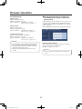
Information display menu
When the [Info] button is clicked, the menu panel displays
the Information display menu panel.
[Manager]
This column displays the All-In-One Headset or Belt Pack
that is set as the manager All-In-One Headset or Belt Pack.
“A” is displayed for the manager of Lane A.
“B” is displayed for the manager of Lane B.
1
[Version]
This column displays the version of the All-In-One Headset
or Belt Pack software.
2
[Group]
This column displays the group to which the All-In-One
Headset or Belt Pack belongs. This setting can be changed
through operations on the Center Module.
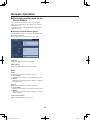
wwChecking the status of alerts
1[Headsets] button
This screen is used to check the status of security alerts and
error alerts from the Center Module.
To display this screen, click the [Alert] button in the
Information display menu panel.
This button is used to check the status of All-In-One
Headsets and Belt Packs registered to the Center
Module.
2[Alert] button
qqChecking the status of security alerts
[Security alert]
This button is used to check the status of security alerts
and error alerts from the Center Module.
This tab displays security alerts that are currently occurring.
wwChecking the status of All-InOne Headsets and Belt Packs
This tab is used to check the status of All-In-One Headsets
or Belt Packs that are registered to the Center Module.
To display this screen, click the [Headsets] button in the
Information display menu panel.
[Initiation time]
This column displays the time and date of security alerts.
[Last used date & time]
This column displays the date and time that the All-In-One
Headset or Belt Pack was last used.
[Cause]
This column displays the cause of security alerts that are
occurring.
[Headset no.]
This column displays the number of the All-In-One Headset
or Belt Pack.
Note
pp The number of the All-In-One Headset or Belt Pack
can be checked with the voice prompt that sounds
when the All-In-One Headset or Belt Pack is turned
on.
33
WX-CC411_PGQP1741ZA_BG_en.indd
33
2014/01/17
15:17:47
Information display menu
qqChecking the status of system alerts
[System alert]
This tab displays information about errors that are occurring
in devices that comprise the Center Module.
[Initiation time]
This column displays the time and date of system alerts.
[Cause]
This column displays the cause of system alerts that are
occurring.
Important
pp Operation of the Center Module cannot be continued
during an error alert. Promptly inquire with the dealer
if an error alert occurs.
34
WX-CC411_PGQP1741ZA_BG_en.indd
34
2014/01/17
15:17:47
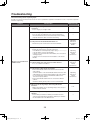
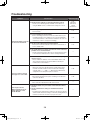
Troubleshooting
Check the following before requesting repair.
Consult your sales shop if these measures do not resolve a problem, if symptoms not listed here occur, or if you have a question
related to engineering.
Symptom
Access is not possible from
a Web browser.
Cause/solution
Reference pages
pp Is a category 5e or higher cable connected to the network
connector?
Use a category 5e or higher cable.
—
pp Is the link lamp lit up?
If it is not lit up, the LAN may not be connected properly or
the network that the unit is connected to may not be working
properly. Check the cable connections and wiring.
—
pp Is the power for the Center Module turned on?
Check if the power is turned on for the Center Module.
Operating
Instructions
<Installation
Guide>
pp Are you accessing the wrong IP address?
Follow the steps below to check the connection.
In the Windows command prompt, input > ping ***.***.***.*** (***
is the IP address of the Center Module).
If “Reply” is received from the Center Module, the connection is
working properly.
If “Reply” is not received, check the IP address of the Center
Module.
Operating
Instructions
<Setup
Instructions>
pp Is the IP address the same as that of another device?
If so, use a different IP address.
Operating
Instructions
<Setup
Instructions>
pp Is the network subnet mask set properly?
If the Center Module and the PC are both connected in the
same subnet:
Set the IP address of the Center Module and the PC to the same
subnet. When accessing the Center Module in the same subnet,
it is recommended to set the Center Module address to the
“remove from proxy” address.
If the Center Module and the PC are connected to different
subnets:
Check the default gateway value set to the Center Module.
Operating
Instructions
<Setup
Instructions>
pp Did you try accessing “http://” while using the HTTPS
function?
When using HTTPS, access by writing “https://”. Also, the port
number must be entered.
P. 12
pp Did you change the HTTP port number or HTTPS port
number?
If the HTTP port number or HTTPS port number has been
changed, input “http://Center Module IP address:port number”
into the address bar of the Web browser.
—
35
WX-CC411_PGQP1741ZA_BG_en.indd
35
2014/01/17
15:17:47
Troubleshooting
Symptom
Cause/solution
pp Are the network settings for the Center Module incorrect?
Set the correct default gateway and DNS server address. If
using the DDNS service, confirm that the settings are correct.
The Center Module cannot be
accessed via the Internet.
It is not possible to upload
message voice source files.
The images from the
Network Cameras are not
being displayed on the
Center Module.
Reference pages
P. 12
Operating
Instructions
<Setup
Instructions>
pp Is “default gateway” set for the network?
Set it correctly.
P. 12
pp Is port forwarding set for the router?
If the router being used does not have the UPnP function, port
forwarding must be set to enable access to the Center Module
via the Internet. Refer to the instruction manual for the router for
instructions on how to set up port forwarding.
P. 13
pp Has the router’s UPnP function been disabled?
Refer to the instruction manual for the router for instructions on
how to enable UPnP.
P. 13
pp Has packet filtering or another tool been set on the router that
prohibits access via the Internet?
Set the router being used to allow access via the Internet. Refer
to the instruction manual for the router for setting instructions.
—
pp Is the IP address for the local network (local address) being
used for access?
Access with the IP address of the Center Module that is used
when using the Internet as the global address and the port
number of the Center Module.
—
pp Has an SD card been inserted?
These files cannot be uploaded unless an SD card has been
inserted. If an SD card has not been inserted, the remaining
capacity reads “----------KB/----------KB” when the [SD memory
card] button in the Setup menu panel is clicked.
P. 26
pp Is there insufficient space on the SD card?
Files that are larger than the space remaining on the SD card
cannot be uploaded.
P. 26
pp Is the SD card locked?
Files cannot be uploaded if the SD card is locked.
—
pp Are the IP address and port number of the Network Cameras
correct?
pp Are the authentication settings for the Network Cameras
correct?
Confirm that the authentication settings for the network cameras
and the “Network Camera settings” of this unit (“Setting Network
Cameras connected to the unit”on p.15) are the same.
—
36
WX-CC411_PGQP1741ZA_BG_en.indd
36
2014/01/17
15:17:47
© Panasonic System Networks Co., Ltd. 2014
WX-CC411_PGQP1741ZA_BG_en.indd
37
F0114-0
PGQP1741ZA
2014/01/17
15:17:47