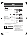
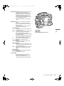
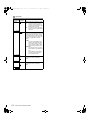
1
Panasonic Broadcast AJ-HPX3700 Menu Information AJ-HPX3700G-VQT1V68_eng.book 166 ページ 2008年10月15日 水曜日 午後6時38分 Menu Menu Configuration MENU USER MENU SYSTEM SETTING MAIN MENU PAINT OPTION MENU OPTION RB GAIN CONTROL RGB BLACK CONTROL MATRIX COLOR CORRECTION LOW SETTING MID SETTING HIGH SETTING ADDITIONAL DTL SKIN TONE DTL KNEE/LEVEL GAMMA CAMERA SETTING VF CAM OPERATION Opening the Menus CAMERA ID SHUTTER SPEED SHUTTER SELECT USER SW SW MODE WHITE BALANCE MODE LENS/IRIS MAIN OPERATION USER MENU: Displayed when the MENU button is pressed. MAIN MENU: Displayed when the MENU button is pressed for at least 3 seconds. OPTION MENU: Displayed when the MENU button is pressed while pressing the LIGHT button. FILE SD CARD READ/WRITE SD CARD R/W SELECT CAC FILE CARD READ LENS FILE LENS FILE CARD R/W SCENE INITIALIZE MAINTENANCE USER MENU SELECT [SELECT MODE] SYSTEM SETTING PAINT VF CAM OPE MAIN OPE FILE MAINTENANCE SYSTEM MODE OPTION MODE REC FUNCTION OUTPUT SEL HD SDI A・B OUT MARKER MONI OUT MARKER LCD MONITOR GENLOCK VF DISPLAY VF MARKER VF USER BOX VF INDICATOR1 VF INDICATOR2 VF INDICATOR3 MODE CHECK IND ! LED BATTERY/P2CARD BATTERY SETTING1 BATTERY SETTING2 MIC/AUDIO 1 MIC/AUDIO 2 TC/UB UMID SET/INFO LENS ADJ BLACK SHADING WHITE SHADING LENS FILE ADJ CAC ADJ DIAGNOSTIC1 DIAGNOSTIC2 HOURS METER Notes The items highlighted in grey cannot be selected by <USER MENU SELECT>. The underlined items can only be selected by <USER MENU SELECT> as one whole page (with all sub-items). Individual sub-items cannot be selected separately. About Menu Description Tables Items/ Adjustable Data Saved Range SCAN REVERSE OFF ON Remarks This setting is for correcting an image which has been inverted by a film-use lens or anamorphic lens attached to the unit. S C U F R a 166 b Menu: Menu Configuration c a. The following letters indicate whether the modified menu data is saved to or read out from the memory. The – indicates that the data cannot be saved or read. S = Can be saved and read as scene file data. C = Can be saved or read using SD CARD READ/WRITE. U = Can be saved and read as user data. Please refer to [SCENE] (page 203) and [INITIALIZE] (page 203). F = Can be read using READ FACTORY DATA. Please refer to [INITIALIZE] (page 203). R = Can set whether or not to store changes using the RC DATA SAVE menu option. Please refer to [Connection of the remote control unit (AJRC10G)] (page 123). b. This section shows the adjustable range of the set value, and available options for this item. c. About the settings available for this item. AJ-HPX3700G-VQT1V68_eng.book 167 ページ 2008年10月15日 水曜日 午後6時38分 USER MENU:USER MENU is factory-set. The menu can be configured to suit your preferences by specifying each option according to your purposes and frequency of use, through the <USER MENU SELECT> screen, which is accessible from the MAIN MENU page. For more information, see [Selecting Options for USER MENU] (page 169). To display USER MENU, press the MENU button. a MAIN MENU: Allows you to set all options on the settings menu. This menu has a category-by-category structure, layered according to purposes and frequency of use. To display MAIN MENU, press the MENU button for 3 seconds or longer. c b a. b. c. d. LIGHT button Jog dial button MENU button SHOT MARKER/MENU CANCEL button Menu SYSTEM SETTING: This option is used to specify recording signal, recording system, etc. PAINT: This option is used to fine-adjust images while monitoring the output waveform of the camera, using the waveform monitor. Normally, this adjustment requires assistance from a video engineer. This option may be performed by an external remote control. However, it is valid when the unit is used as a stand-alone device. VF: Used to select the information items to be displayed in the viewfinder screen. CAM OPERATION: Used to change settings according to the conditions for the subject. MAIN OPERATION: Used to specify recording-related items, such as audio settings, time code, battery and P2 card remaining amounts. FILE: Used to specify file-related items such as SD memory card reading/writing and lens file settings. MAINTENANCE: Used to specify maintenance-related items. USER MENU SELECT: Used to edit USER MENU. d OPTION MENU: Provides options which may be needed if functions are added in the future. To display OPTION MENU, hold down the LIGHT button and press the MENU button. Menu: Menu Configuration 167 AJ-HPX3700G-VQT1V68_eng.book 168 ページ 2008年10月15日 水曜日 午後6時38分 Setting Menu Options The menu options are set with the MENU and jog dial buttons. The menu comprises main menu, sub-menus and options menus. The data specified through menu options are written and saved in the internal memory of the unit. This section describes how to set options in MAIN MENU. The other menus can be configured in the same manner (the method of displaying the menu screen depends on the particular menu). 4 Turn the jog dial button to move the mark () to a desired option. Then, press the jog dial button. The value starts blinking. Note When the unit is in thumbnail mode, the viewfinder displays “THUMBNAIL OPEN”, disabling navigation through the menu. 1 Press the MENU button for 3 seconds or longer. The MAIN MENU screen appears, together with its options. 2 Turn the jog dial button to move the mark () to a desired menu option. Then, press the jog dial button to display the sub-menu screen. 3 Turn the jog dial button to move the mark () to a desired menu option. Then, press the jog dial button to display the options screen. 168 Menu: Menu Configuration 5 Turn the jog dial button to change the value. To increase the value: Turn the jog dial button clockwise, as seen from the front of the camera. To decrease the value: Turn the jog dial button anti-clockwise, as seen from the front of the camera. Each turn of the dial switches the value by one step. A quick turn changes the value rapidly; a slow turn makes a fine adjustment. To turn an option on or off: To select “ON”, turn the jog dial button clockwise, as seen from the front of the camera. To select “OFF”, turn the jog dial button anti-clockwise, as seen from the front of the camera. To return the changed set value to the previous one: To return the changed value to the previous one, press the SHOT MARKER/MENU CANCEL button once while the changed value is flashing and “PUSH CANCEL BACK TO PREV” will appear. Press the SHOT MARKER/MENU CANCEL button again to return the set value to the value before the change. Notes The following menu items cannot be canceled using the SHOT MARKER/MENU CANCEL button. – Pages on the USER MENU SELECT screen – Pages on the FILE screen – CAMERA ID – Part of the WHITE BALANCE MODE pages – BATTERY SETTING1, 2 – UMID SET/INFO In the 1080/23.98P and 1080/24P modes, the menu displayed on the LCD monitor may blink. This is normal, and does not indicate that a fault has occurred. AJ-HPX3700G-VQT1V68_eng.book 169 ページ 2008年10月15日 水曜日 午後6時38分 6 7 8 Press the jog dial button. The value stops blinking and is accepted. To change the settings for other options on the same page, repeat steps 4 - 6. When the settings are finalized, press the MENU button. This terminates the menu option setting mode and returns the unit to normal operation mode. Selecting Options for USER MENU Go to the USER MENU SELECT page from MAIN MENU. Then, open relevant menu screens to select options to add to USER MENU. Only the selected options are displayed as options in USER MENU. For information about how to navigate this menu, see [Setting Menu Options] (page 168). Menu Note Options with [ ] are effective. The number of options that can be added to USER MENU is 14 3=42 (3 pages of options) for camera-related options, and 14 (1 page of options) for memory-related options. Note, however, that the number of options that can be added is reduced if menu options not normally displayed in the selected mode are added. Menu: Menu Configuration 169 AJ-HPX3700G-VQT1V68_eng.book 170 ページ 2008年10月15日 水曜日 午後6時38分 Menu Description Tables SYSTEM SETTING The ____ in the Adjustable Range column indicates the preset mode. SYSTEM MODE Items/ Adjustable Data Saved Range SYSTEM MODE 1080-59.94i 1080-23.98PsF 1080-24PsF 1080-50i Remarks For setting the system frequency. When this item is switched, turn off the POWER switch on the unit and then turn it on again. Notes When USB DEVICE mode is selected, no change can be made to this option. When the remote control unit (AJRC10G) is connected, this item is not displayed. S C U F – Used to set the codec mode and the recording/shooting mode. DVCPROHD: Recording is performed using DVCPRO HD codec. AVC-I 100: Recording is performed using AVC-Intra100 codec. AVC-I 50: Recording is performed using AVC-Intra50 codec. REC FORMAT DVCPROHD/60i AVC-I 100/60i AVC-I 100/30PN AVC-I 100/24PN AVC-I 50/60i AVC-I 50/30PN AVC-I 50/24PN Used when SYSTEM MODE is set to 1080-59.94i. When DVCPROHD/60i is selected, it is possible to refine the shooting mode selection by setting CAMERA MODE. AVC-I 100/24PN AVC-I 50/24PN Used when SYSTEM MODE is set to 1080-23.98PsF or 1080-24PsF. DVCPROHD/50i AVC-I 100/50i AVC-I 100/25PN AVC-I 50/50i AVC-I 50/25PN Used when SYSTEM MODE is set to 1080-50i. When DVCPROHD/50i is selected, it is possible to refine the shooting mode selection by setting CAMERA MODE. S C U F R Items/ Adjustable Data Saved Range CAMERA MODE (DVCPROHD/ 60i of 108059.94i) 60i 30P 24P 24PA (DVCPROHD/ 50i of 1080-50i) 50i 25P (Modes other than the above) 24P 25P Menu: Menu Description Tables When using the DVCPRO HD recording format in the 1080-60i or 1080-50i modes, the pull-down method (conventional camera mode) will be set. S C U F R VFR OFF ON This is for setting the variable frame rate. OFF: Operates with a fixed frame number. Operates with a frame rate set using REC FORMAT. ON: Operates with a variable frame rate. Operates with a frame rate set using FRAME RATE. Note When INTERVAL REC or LOOP REC is set, this setting is set to “OFF”. S C U F R 24P VFR RANGE 24FRAME 30FRAME Select the upper limit of the frame rate that can be changed during VFR. This item is displayed only when “108023.98PsF” or “1080-24PsF” is selected in SYSTEM MODE. Note Sequence of the HD SDI output signal will be disturbed when this item is set to “30FRAME” and FRAME RATE is set to “24-30FRAME”, but this is not a malfunction. – – – F – FRAME RATE S C U F R 170 Remarks (1080-59.94i, 1080-23.98PsF, 1080-24PsF) 1FRAME : 24FRAME : 30FRAME (1080-50i) 1FRAME : 25FRAME This is for setting the shooting frame number during VFR operation. When the mode has been changed using other settings and the frame rate value set here exceeds the maximum frame rate allowed by the set mode, the maximum frame rate is changed to the maximum frame rate of the set mode. AJ-HPX3700G-VQT1V68_eng.book 171 ページ 2008年10月15日 水曜日 午後6時38分 Items/ Adjustable Data Saved Range USR SW F.RATE (1080-59.94i, 1080-23.98PsF, 1080-24PsF) 1FRAME : 24FRAME : 30FRAME (1080-50i) 1FRAME : 25FRAME Remarks When the FRATE function has been assigned to a user button, the starting frame rate under VFR operation is set. When the mode has been changed using other settings and the frame rate value set here exceeds the maximum frame rate allowed by the set mode, the maximum frame rate is changed to the maximum frame rate of the set mode. OPTION MODE Items/ Adjustable Data Saved Range ACCESS LED OFF SLOT SIDE LCD SIDE BOTH Specify whether or not to enable the P2 card access LEDs. OFF: Disables both LEDs above the slots and on the side panel. SLOT SIDE: Enables the LED above the slots and disables the LED on the side panel. LCD SIDE: Enables the LED on the side panel and disables the LED above the slots. BOTH: Enables both LEDs above the slots and on the side panel. HOLD CLEAR Select whether or not to hold the UMID GPS position information while the power is turned off, thereby keeping this information as status data holding the previous value until the power is turned on again, which enables a new measurement to start. HOLD: Hold and save the data. CLEAR: Clear the data when the power is turned off, and save zero (NoInfo) from the next power-on until a new measurement is completed. S C U F R SCAN REVERSE ON OFF This setting is for correcting an image which has been inverted by a film-use lens or anamorphic lens attached to the unit. S C U F R PC MODE SEL USB HOST USB DEV. – – – F – PC MODE ON OFF Used to enable or disable the mode that allows the unit to be connected to a PC or an external hard disk drive via USB 2.0. ON: Sets the unit to the mode selected through the PC MODE SELECT menu option. OFF: Disables the PC MODE for normal operation. Note Once the power is turned off, the option is always set to “OFF” when the power is turned on next time. – C U F – P.OFF GPS DATA Menu This is for setting the operations mode of this unit when PC MODE is set to “ON” and an external device is connected to the USB connector. USB HOST: Allows data transfer from the unit to the USB-connected device. USB DEV.: Allows data transfer from the USB-connected device to the unit. Note When the PC MODE menu option is set to “ON”, no change can be made to this option. Remarks – C U F – SDI METADATA ON OFF Used to specify whether or not to output metadata (UMID) to HD SDI. – C U F – SAVE SW (AUD ON OUT) OFF Select whether or not to forcibly disable the audio output when the SAVE ON/ OFF switch is set to [ON]. ON: Disable audio output. OFF: Enable audio output. – C U F – SAVE SW (LCD) ON OFF – – – F – Select whether or not to automatically turn off the LCD monitor when the SAVE ON/OFF switch is set to [ON]. ON: Turn off LCD monitor. OFF: Do not turn off LCD monitor. – C U F – Menu: Menu Description Tables 171 AJ-HPX3700G-VQT1V68_eng.book 172 ページ 2008年10月15日 水曜日 午後6時38分 REC FUNCTION Items/ Adjustable Data Saved Range INTERVAL REC ON MODE ONE SHOT OFF Remarks Sets INTERVAL REC function. ON: Uses internal memory to perform interval recording. ONE SHOT: Performs “one-shot” recording for the duration specified under REC TIME, and then stops. OFF: INTERVAL REC is not performed. Note This item cannot be changed when “ON” is selected in LOOP REC MODE. Items/ Adjustable Data Saved Range Select whether or not to enable PRE RECORDING. ON: PRE RECORDING enabled. OFF: PRE RECORDING disabled. Note Specify the PRE RECORDING time by using the menu option PRE REC TIME. PRE REC MODE ON OFF – C U F – PRE REC TIME 1SEC : 8SEC Set PRE RECORDING. 1-8SEC: Set the length of time that can be retrospectively recorded before the REC START button is pressed. ON OFF Select whether or not to enable LOOP REC. This setting can be used with PRE RECORDING features. ON: Enable LOOP REC. OFF: Disable LOOP REC. Notes After the power is turned off, this item will default to “OFF” the next time the power is turned on. This item cannot be changed when “ON” or “ONE SHOT” is selected in INTERVAL REC MODE. ALL NORMAL Select operating modes that allow recording to start. ALL: Allow recording to start during stop, recording pause, and playback. NORMAL: Allow recording to start during stop and recording pause. Note Even if this is set to “ALL”, the operation is “NORMAL”, when “ON” or “ONE SHOT” is selected in INTERVAL REC MODE. – C U F – INTERVAL REC ON HOLD OFF Selects whether INTERVAL REC MODE settings are retained or not when the power is turned off once. ON: Retain OFF: Do not retain. The INTERVAL REC MODE is “OFF” whenever the power is turned on again. – C U F – LOOP REC MODE – C U F – REC TIME* 00s01f : 59s29f Set recording time for INTERVAL REC (1 cut). Note However the settings can be made frame by frame, and the numbers of the cut-off unit frames for the shortest time period and the set time on the actual operation may vary with the recording method. For details, refer to [Interval Recording] (page 44). – – – F – REC START – C U F – PAUSE TIME* 00h00m00s01f : 00h04m59s23f : 23h59m59s29f Specify pause time for INTERVAL REC. Note However the settings can be made frame by frame, and the numbers of the cut-off unit frames for the shortest time period and the set time on the actual operation may vary with the recording method. For details, refer to [Interval Recording] (page 44). NONE : 5day Specify the time needed for INTERVAL REC. Select from “NONE” (continue until operation is manually stopped) to 5 days. NONE 00m00s01f : 99m59s29f OVER100min Display total recorded time for INTERVAL REC. The setting cannot be changed using this option. Displays the recording time (recording time needed for the P2 card) calculated using REC TIME, PAUSE TIME, and TAKE TOTAL TIME. Note A value based on actual processing is displayed. – C U F – TAKE TOTAL TIME – C U F – Select the recording order of the slot when the power is turned on. HOLD: The recording order starts with the card previously selected when the power was turned off. SLOT1: The recording order starts with the card that is inserted in slot 1 when the power is turned on. P.ON REC SLOT HOLD SEL SLOT1 – C U F – TOTAL REC TIME* – – – – – AUDIO REC ON OFF Select whether or not sound will be recorded during INTERVAL REC. 0SEC : 10SEC Set the delay after pressing REC START to start recording in INTERVAL REC. – C U F – START DELAY – C U F – Note Displayed REC TIME, PAUSE TIME and TOTAL REC TIME are translated into either drop-frame or non-drop-frame according to the mode of operation. TAKE TOTAL TIME is actual time. Therefore, TOTAL REC TIME may incorporate fractions, depending on the settings. Example of drop-frame – C U F – * This variable range is the numerical values for 59.94 Hz. For 50 Hz, the frame rate is up to 24f. The frame rate is up to 23f in 24PN (Native) mode. 172 Remarks Menu: Menu Description Tables REC TIME 02s00f PAUSE TIME 02s00f TAKE TOTAL TIME 40min TOTAL REC TIME 19m59s06f AJ-HPX3700G-VQT1V68_eng.book 173 ページ 2008年10月15日 水曜日 午後6時38分 OUTPUT SEL Items/ Adjustable Data Saved Range SIGNAL FORMAT 4:2:2 4:4:4 Remarks Select the signal that is output from the HD SDI A · B connectors. 4:2:2: YPBPR 4:2:2 format is selected. 4:4:4: RGB 4:4:4 format is selected. LINK A will be output from the HD SDI A connector, and LINK B from the HD SDI B connector. Items/ Adjustable Data Saved Range MONITOR OUT VBS HD SDI Select the output signal on the MON OUT connector. ON OFF This sets whether to perform telecine conversion correction on the MON OUT, RC OUT, and LCD OUT signals when GAMMA MODE SEL is set to “FILMREC”. ON: Correction is performed. OFF: Correction is not performed. VF-OFF LCD-OFF ON This sets whether to superimpose characters on the video shown on the LCD monitor and in the viewfinder. Note, however, that the characters are output to one of the MON OUT, VF OUT and LCD OUT signals. MEM CAM Select the image to display in the viewfinder. MEM: Display the playback image in the playback mode. Display the camera image at other times. CAM: Always display the camera image. MONO COLOR Select the video signal that is output to the viewfinder connector. MONO: Output the Y signal alone to the viewfinder connector. COLOR: Output the Y, PB, and PR signals to the viewfinder connector. ON OFF Select whether or not to output clip thumbnails displayed on the LCD monitor to the MON OUT (VBS) signal and the REMOTE connector. ON: Enable output. OFF: Disable output. Note Even when the MON OUT OUTPUT SEL switch is in the [CAM] position, thumbnails are output when this option is set to “ON”. SQUEEZE LT-BOX For setting the mode of the down converter output signals. – C U F – MONITOR GAMMA – C U F – P-10LOG ON OFF ON: OFF: P-10LOG format signal is output. This is valid when GAMMA MODE SEL is set to “FILMREC”, and SIGNAL FORMAT is set to “4:4:4”. Signal format set in GAMMA MODE SEL is output. Note If you select “ON” in this item, 2D-CMS will operate simultaneously as well. – C U F – VF/LCD CHAR – C U F – OUTPUT ITEM VF MODE Set the character contents superimposed onto the output signals for the HD SDI A · B connector and MON OUT connector. MENU ONLY: Displays only when the menu characters are superimposed. No display appears when other characters are superimposed. TC: Display the time code. (Displays the menu when menu characters are superimposed.) Note that when 1080/23.98PsF or 1080/24PsF has been selected in the SYSTEM MODE menu option, the frame digits will not be updated correctly. STATUS: Display the same characters superimposed on the viewfinder signal. (Displays the menu when menu characters are superimposed.) – C U F – VF SEL – C U F – THUMBNAIL OUT – C U F – HD SDI A · B CHAR OFF A B BOTH Select whether to superimpose characters on the HD SDI A · B connector. (The character content output from the HD SDI A · B and MON OUT connectors is the same.) OFF: The characters are not superimposed. A: The characters are superimposed on the HD SDI A connector. B: The characters are superimposed on the HD SDI B connector. BOTH: The characters are superimposed on the HD SDI A connector and the HD SDI B connector. Menu – C U F – MENU ONLY TC STATUS Remarks – C U F – DOWNCON MODE – C U F – – C U F – Menu: Menu Description Tables 173 AJ-HPX3700G-VQT1V68_eng.book 174 ページ 2008年10月15日 水曜日 午後6時38分 HD SDI A · B OUT MARKER Items/ Adjustable Data Saved Range MARKER SW OFF A B BOTH Remarks Switches the marker on and off. OFF: The characters are not superimposed. A: The characters are superimposed on the HD SDI A connector. B: The characters are superimposed on the HD SDI B connector. BOTH: The characters are superimposed on the HD SDI A connector and the HD SDI B connector. Items/ Adjustable Data Saved Range FRAME SIG Switch the center mark. OFF: Do not display center mark. 1: + (large) 2: Hollow (large) 3: + (small) 4: Hollow (small) – C U F R SAFETY MARK OFF 1 2 Select the frame type for the safety zone. OFF: Do not display frame. 1: Box 4:3 13:9 14:9 VISTA CNSCO Set the frame marker. The VISTA ratio is 16:8.65. The CNSCO ratio is 16:6.81. ON OFF For setting whether to include the user box in the signal from the HD SDI A · B connector. 1 : 13 : 100 For setting the width of the user box. 1 : 13 : 100 For setting the height of the user box. –50 : +00 : +50 For setting the horizontal position of the user box center. –50 : +00 : +50 For setting the vertical position of the user box center. – C U F R USER BOX – C U F R USER BOX WIDTH – C U F R CENTER MARK OFF 1 2 3 4 Remarks – C U F R USER BOX HEIGHT – C U F R USER BOX H POS – C U F R 2: Corner frame – C U F R – C U F R SAFETY AREA 80% : 90% : 100% For setting the size of the safety marker. It is possible to set the size by units of 1% with a fixed ratio between of width and height. ON OFF Set the frame marker to “ON” or “OFF”. – C U F R FRAME MARK – C U F R 174 USER BOX V POS Menu: Menu Description Tables AJ-HPX3700G-VQT1V68_eng.book 175 ページ 2008年10月15日 水曜日 午後6時38分 MONI OUT MARKER Items/ Adjustable Data Saved Range CENTER MARK OFF 1 2 3 4 LCD MONITOR Remarks Switch the center mark. OFF: Do not display center mark. 1: + (large) 2: Hollow (large) 3: + (small) 4: Hollow (small) – C U F R SAFETY MARK OFF 1 2 Select the frame type for the safety zone. OFF: Do not display frame. 1: Box Items/ Adjustable Data Saved Range BRIGHTNESS –7 : +0 : +7 Adjust the LCD monitor brightness. –7 : +0 : +7 Adjust the LCD monitor chroma level. –7 : +0 : +7 Adjust the LCD monitor contrast. NORMAL HIGH Adjust the backlight. NORMAL: Mode normally used HIGH: This is brighter than NORMAL. NORMAL MIRROR Select whether or not to change the LCD monitor to mirror image. NORMAL: Do not change to mirror image. MIRROR: Change to mirror image. – C U F – COLOR LEVEL – C U F – CONTRAST 2: Remarks Corner frame – C U F – BACKLIGHT – C U F R 80% : 90% : 100% For setting the size of the safety marker. It is possible to set the size by units of 1% with a fixed ratio between of width and height. ON OFF Set the frame marker to “ON” or “OFF”. 4:3 13:9 14:9 VISTA CNSCO Set the frame marker. The VISTA ratio is 16:8.65. The CNSCO ratio is 16:6.81. ON OFF For setting whether to include the user box in the signal from the MON OUT connector. 1 : 13 : 100 For setting the width of the user box. 1 : 13 : 100 For setting the height of the user box. –50 : +00 : +50 For setting the horizontal position of the user box center. –50 : +00 : +50 For setting the vertical position of the user box center. – C U F – SELF SHOOT – C U F R FRAME MARK – C U F R FRAME SIG Menu SAFETY AREA – C U F – – C U F R USER BOX – C U F R USER BOX WIDTH – C U F R USER BOX HEIGHT – C U F R USER BOX H POS – C U F R USER BOX V POS – C U F R Menu: Menu Description Tables 175 AJ-HPX3700G-VQT1V68_eng.book 176 ページ 2008年10月15日 水曜日 午後6時38分 GENLOCK Items/ Adjustable Data Saved Range GENLOCK Remarks INT EXT Switch the camera synchronizing signal. INT: Synchronize with the internal reference signal regardless of the reference signal input to the GENLOCK IN connector. EXT: Synchronize with the reference signal input to the GENLOCK IN connector. HD SDI COMPOSIT For selecting the output signals that lock phases to the signals that are input in the GENLOCK IN connector. Note, however, that in 1080/23.98PsF mode and 1080/ 24PsF mode, the phase is locked to HD SDI even if “COMPOSIT” has been selected. HD SDI: For locking the HD SDI output signals to the GENLOCK input. For the down converter output signals, the start position of the video delays by about 90 lines. COMPOSIT: For locking the down converter output signals to the GENLOCK input. For the HD SDI output signals, the start position of the video gains by about 90 lines. –100 : +000 : +100 Perform coarse phase adjustment for horizontal hold when configuring a system. –100 : +000 : +100 Perform fine phase adjustment for horizontal hold when configuring a system. – C U F R GL PHASE – C U F R H PHASE COARSE – – – – – H PHASE FINE – – – – – 176 Menu: Menu Description Tables AJ-HPX3700G-VQT1V68_eng.book 177 ページ 2008年10月15日 水曜日 午後6時38分 PAINT The ____ in the Adjustable Range column indicates the preset mode. RB GAIN CONTROL Items/ Adjustable Data Saved Range R GAIN AWB PRE* RGB BLACK CONTROL Remarks –200 : +000 : +200 For setting the Rch gain when the WHITE BAL switch is in the [PRST] position. MASTER PED* –200 : +000 : +200 For setting the Bch gain when the WHITE BAL switch is in the [PRST] position. R PEDESTAL* For setting the Rch gain when the WHITE BAL switch is in the [A] position. G PEDESTAL* For setting the Bch gain when the WHITE BAL switch is in the [A] position. B PEDESTAL* For setting the Rch gain when the WHITE BAL switch is in the [B] position. PEDESTAL OFFSET* S C U F R B GAIN AWB PRE* Items/ Adjustable Data Saved Range –200 : +000 : +200 For setting the level of the master pedestal. –100 : +000 : +100 For setting the pedestal level of the Rch. –100 : +000 : +100 For setting the pedestal level of the Gch. –100 : +000 : +100 For setting the pedestal level of the Bch. ON OFF For setting the pedestal levels of the Rch, the Gch and the Bch when the auto black balance is adjusted. ON: To retain the values set in the respective items of R PEDESTAL, G PEDESTAL, and B PEDESTAL OFF: The pedestal levels of the Rch, the Gch and the Bch are set to “0”. –100 : +000 : +100 For adjusting the flare level of the Rch. Adjustment values in this item are added to the flare adjustment value that is adjusted on <LENS FILE ADJ> screen. –100 : +000 : +100 For adjusting the flare level of the Gch. Adjustment values in this item are added to the flare adjustment value that is adjusted on <LENS FILE ADJ> screen. –100 : +000 : +100 For adjusting the flare level of the Bch. Adjustment values in this item are added to the flare adjustment value that is adjusted on <LENS FILE ADJ> screen. S C U F R S C U F R S C U F R S C U F R S C U F R B GAIN AWB A* –200 : +000 : +200 S C U F R S C U F R R GAIN AWB B* –200 : +000 : +200 S C U F R B GAIN AWB B* –200 : +000 : +200 For setting the Bch gain when the WHITE BAL switch is in the [B] position. S C U F R S C U F – ON OFF For setting the values of the Rch gain and the Bch gain when the auto white balance is executed as the WHITE BAL switch is in the [A] position. ON: To retain the values set in the items of R GAIN AWB A and B GAIN AWB A OFF: The values of the Rch gain and the Bch gain is set to “0”. R FLARE* S C U F R G FLARE* S C U F R AWB B GAIN OFFSET* Menu R GAIN AWB A* –200 : +000 : +200 AWB A GAIN OFFSET* Remarks ON OFF For setting the values of the Rch gain and the Bch gain when the auto white balance is executed as the WHITE BAL switch is in the [B] position. ON: To retain the values set in the items of R GAIN AWB B and B GAIN AWB B OFF: The values of the Rch gain and the Bch gain is set to “0”. S C U F R B FLARE* S C U F R * If the remote control unit is connected, settings made from the menu are disabled. (The set value is displayed.) S C U F R Menu: Menu Description Tables 177 AJ-HPX3700G-VQT1V68_eng.book 178 ページ 2008年10月15日 水曜日 午後6時38分 MATRIX COLOR CORRECTION Items/ Adjustable Data Saved Range MATRIX TABLE Remarks A B For selecting the color correction table for the linear matrix. –63 : +31 : +63 For performing the linear matrix adjustment. (red/green) –63 : –04 : +63 For performing the linear matrix adjustment. (red/blue) –63 : –01 : +63 For performing the linear matrix adjustment. (green/red) –63 : +04 : +63 For performing the linear matrix adjustment. (green/blue) –63 : +01 : +63 For performing the linear matrix adjustment. (blue/red) –63 : –01 : +63 For performing the linear matrix adjustment. (blue/green) OFF A B For selecting the color correction table when the GAIN switch is in the [L] position. OFF A B For selecting the color correction table when the GAIN switch is in the [M] position. Items/ Adjustable Data Saved Range R (SAT) S C U F R MATRIX R-G S C U F R M MATRIX TABLE S C U F – H MATRIX TABLE OFF A B For selecting the color correction table when the GAIN switch is in the [H] position. S C U F – Notes The items indicated by are the setting items for PAINT MENU SW() R/W in the <SD CARD R/W SELECT> screen. The items without are the setting items for PAINT MENU LEVEL R/W. Please refer to [SD CARD R/W SELECT] (page 201) for more information. In the preset mode, the linear matrix data of MATRIX TABLE B are all set to “+00”. Menu: Menu Description Tables –63 : +00 : +63 For performing the color saturation correction between magenta and blue. –63 : +00 : +63 For performing the color saturation correction of blue. –63 : +00 : +63 For performing the color saturation correction between blue and cyan. –63 : +00 : +63 For performing the color saturation correction of cyan. –63 : +00 : +63 For performing the color saturation correction between cyan and green. –63 : +00 : +63 For performing the color saturation correction of green. –63 : +00 : +63 For performing the color saturation correction between green and yellow. –63 : +00 : +63 For performing the color saturation correction of yellow. –63 : +00 : +63 For performing the color saturation correction between yellow and red. S C U F R Cy-G (SAT) S C U F R G (SAT) S C U F R G-Yl (SAT) S C U F R Yl (SAT) S C U F R Yl-R (SAT) S C U F R 178 For performing the color saturation correction of magenta. S C U F R Cy (SAT) S C U F R L MATRIX TABLE –63 : +00 : +63 S C U F R B-Cy (SAT) S C U F R MATRIX B-G For performing the color saturation correction between red and magenta. S C U F R B (SAT) S C U F R MATRIX B-R –63 : +00 : +63 S C U F R Mg-B (SAT) S C U F R MATRIX G-B For performing the color saturation correction of red. S C U F R Mg (SAT) S C U F R MATRIX G-R –63 : +00 : +63 S C U F R R-Mg (SAT) S C U F R MATRIX R-B Remarks AJ-HPX3700G-VQT1V68_eng.book 179 ページ 2008年10月15日 水曜日 午後6時38分 Items/ Adjustable Data Saved Range R (PHASE) Remarks –63 : +00 : +63 For performing the hue correction for red. –63 : +00 : +63 For performing the hue correction between red and magenta. –63 : +00 : +63 For performing the hue correction for magenta. –63 : +00 : +63 For performing the hue correction between magenta and blue. –63 : +00 : +63 For performing the hue correction for blue. –63 : +00 : +63 For performing the hue correction between blue and cyan. –63 : +00 : +63 For performing the hue correction for cyan. –63 : +00 : +63 For performing the hue correction between cyan and green. –63 : +00 : +63 For performing the hue correction for green. –63 : +00 : +63 For performing the hue correction between green and yellow. –63 : +00 : +63 For performing the hue correction for yellow. –63 : +00 : +63 For performing the hue correction between yellow and red. Notes ON OFF For switching on/off of the 12-axis independent color correction of the position selected with the GAIN switch ([L], [M], [H]). The items indicated by are the setting items for PAINT MENU SW() R/W in the <SD CARD R/W SELECT> screen. The items without are the setting items for PAINT MENU LEVEL R/W. Please refer to [SD CARD R/W SELECT] (page 201) for more information. S C U F R R-Mg (PHASE) LOW SETTING Items/ Adjustable Data Saved Range MASTER GAIN –3dB : 0dB : 30dB For setting the LEVEL DEPEND. When the Y-detail is emphasized, details of dark sections are compressed. If the numerical value is larger, details of bright sections are also compressed. For setting the master gamma. (0.01 step) S C U F R For setting the gamma curve for the dark portion. –8 to –1: The dark portion is compressed. OFF: Standard state +1 to +8: The dark portion is extended. 1 2 3 For setting the upper limit of compression/expansion. 1: Approximately 20% 2: Approximately 30% 3: Approximately 40% OFF A B For selecting the color correction table for the linear matrix. ON OFF For switching on/off of the 12-axis independent color correction. S C U F R S C U F R COLOR CORRECT S C U F R S C U F R COLOR CORRECT 0.30 : 0.45 : 0.75 BLACK GAMMA –8 : OFF : +8 MATRIX TABLE S C U F R Yl-R (PHASE) For performing the horizontal detail frequency selection. S C U F R S C U F R Yl (PHASE) 00 : 18 : 31 S C U F R B.GAMMA RANGE S C U F R G-Yl (PHASE) For performing the noise elimination level setting for detail. Menu S C U F R G (PHASE) 00 : 04 : 60 S C U F R MASTER GAMMA S C U F R Cy-G (PHASE) For performing the vertical detail correction level setting. LEVEL DEPEND. 0 1 : 5 S C U F R Cy (PHASE) 00 : 15 : 31 S C U F R H.DTL FREQ. S C U F R B-Cy (PHASE) For performing the horizontal detail correction level setting. S C U F R DTL CORING S C U F R B (PHASE) 00 : 10 : 63 S C U F R V.DTL LEVEL S C U F R Mg-B (PHASE) Select the master gain from –3, 0, 3, 6, 9, 12, 15, 18, 21, 24, 27, or 30 dB. S C U F R H.DTL LEVEL S C U F R Mg (PHASE) Remarks S C U F R Menu: Menu Description Tables 179 AJ-HPX3700G-VQT1V68_eng.book 180 ページ 2008年10月15日 水曜日 午後6時38分 When shooting with the MASTER GAIN set to “–3dB”, coloring phenomena may occur in portions of the video with high brightness. The coloring phenomena can be reduced by switching the OUTPUT/AUTO KNEE switch to [CAM/AUTO KNEE OFF], setting the MANUAL KNEE menu option of the <KNEE/LEVEL> screen to “ON”, and then changing the following menu options. – When “HD”, “SD”, “FILMLIKE1”, “FILMLIKE2” or “FILMLIKE3” has been selected in the GAMMA MODE SEL menu option of the <GAMMA> screen, reduce the value in the KNEE MASTER SLOPE menu option of the <KNEE/LEVEL> screen. – When “FILM-REC” has been selected in the GAMMA MODE SEL menu option of the <GAMMA> screen, reduce the value in the F-REC DYNAMIC LVL menu option of the <GAMMA> screen. – When “VIDEO-REC” has been selected in the GAMMA MODE SEL menu option of the <GAMMA> screen, reduce the value in the V-REC KNEE SLOPE menu option of the <GAMMA> screen. MID SETTING Items/ Adjustable Data Saved Range MASTER GAIN –3dB : 3dB : 30dB Remarks Select the master gain from –3, 0, 3, 6, 9, 12, 15, 18, 21, 24, 27, or 30 dB. S C U F – H.DTL LEVEL 00 : 08 : 63 For performing the horizontal detail correction level setting. 00 : 12 : 31 For performing the vertical detail correction level setting. 00 : 12 : 60 For performing the noise elimination level setting for detail. 00 : 18 : 31 For performing the horizontal detail frequency selection. S C U F – V.DTL LEVEL S C U F – DTL CORING S C U F – H.DTL FREQ. S C U F – LEVEL DEPEND. 0 1 : 5 For setting the LEVEL DEPEND. When the Y-detail is emphasized, details of dark sections are compressed. If the numerical value is larger, details of bright sections are also compressed. S C U F – MASTER GAMMA 0.30 : 0.45 : 0.75 For setting the master gamma. (0.01 step) S C U F – BLACK GAMMA –8 : OFF : +8 For setting the gamma curve for the dark portion. –8 to –1: The dark portion is compressed. OFF: Standard state +1 to +8: The dark portion is extended. S C U F – B.GAMMA RANGE 1 2 3 For setting the upper limit of compression/expansion. 1: Approximately 20% 2: Approximately 30% 3: Approximately 40% OFF A B For selecting the color correction table for the linear matrix. ON OFF For switching on/off of the 12-axis independent color correction. S C U F R MATRIX TABLE S C U F – COLOR CORRECT S C U F – 180 Menu: Menu Description Tables AJ-HPX3700G-VQT1V68_eng.book 181 ページ 2008年10月15日 水曜日 午後6時38分 HIGH SETTING Items/ Adjustable Data Saved Range MASTER GAIN –3dB : 6dB : 30dB ADDITIONAL DTL Remarks Select the master gain from –3, 0, 3, 6, 9, 12, 15, 18, 21, 24, 27, or 30 dB. DTL GAIN(+) 00 : 06 : 63 For performing the horizontal detail correction level setting. DTL GAIN(–) 00 : 10 : 31 For performing the vertical detail correction level setting. DTL CLIP For performing the noise elimination level setting for detail. 00 : 18 : 31 For performing the horizontal detail frequency selection. Adjust the detail level toward + (upwards). –31 : +00 : +31 Adjust the detail level toward the – (downwards). 00 : 63 For setting the level for clipping the detail signals. (R+G)/2 (G+B)/2 2G+R+B /4 (3G+R)/4 R G For setting the proportion of the RGB signal components that provide the detail. –31 : +00 : +31 For revising the master detail level. S C U F R DTL SOURCE S C U F R MASTER DTL S C U F – LEVEL DEPEND. 0 : 3 : 5 –31 : +00 : +31 Menu 00 : 12 : 60 S C U F – H.DTL FREQ. For changing the detail level of the high brightness portion. S C U F R S C U F – DTL CORING OFF 1 : 5 S C U F R S C U F – V.DTL LEVEL KNEE APE LVL Remarks S C U F R S C U F – H.DTL LEVEL Items/ Adjustable Data Saved Range For setting the LEVEL DEPEND. When the Y-detail is emphasized, details of dark sections are compressed. If the numerical value is larger, details of bright sections are also compressed. S C U F R S C U F – MASTER GAMMA 0.30 : 0.45 : 0.75 For setting the master gamma. (0.01 step) S C U F – BLACK GAMMA –8 : OFF : +8 For setting the gamma curve for the dark portion. –8 to –1: The dark portion is compressed. OFF: Standard state +1 to +8: The dark portion is extended. S C U F – B.GAMMA RANGE 1 2 3 For setting the upper limit of compression/expansion. 1: Approximately 20% 2: Approximately 30% 3: Approximately 40% OFF A B For selecting the color correction table for the linear matrix. ON OFF For switching on/off of the 12-axis independent color correction. S C U F R MATRIX TABLE S C U F – COLOR CORRECT S C U F – Note The items indicated by are the setting items for PAINT MENU SW() R/W in the <SD CARD R/W SELECT> screen. The items without are the setting items for PAINT MENU LEVEL R/W. Please refer to [SD CARD R/W SELECT] (page 201) for more information. Menu: Menu Description Tables 181 AJ-HPX3700G-VQT1V68_eng.book 182 ページ 2008年10月15日 水曜日 午後6時38分 SKIN TONE DTL Items/ Adjustable Data Saved Range SKIN TONE DTL OFF A B AB Remarks For selecting the skin color table for enabling the skin tone detail. The skin color table is provided in the DETECT TABLE item. By enabling the skin tone detail, it is possible to shoot human skin more accurately. Items/ Adjustable Data Saved Range Y MAX ON OFF For the setting to display the zebra pattern in the skin tone area displayed in the viewfinder screen. The zebra pattern is displayed when this item is turned “ON” and the <SKIN TONE DTL> screen is opened. The zebra pattern indicates the area which is selected in the SKIN TONE DTL item. S C U F R ZEBRA HD SDI A ON OFF For setting to include the skin tone zebra in the HD SDI A signal. The zebra pattern is displayed when this item is turned “ON” and the <SKIN TONE DTL> screen is opened. The zebra pattern indicates the area which is selected in the SKIN TONE DTL item. S C U F R ZEBRA HD SDI B 000 : 190 : 255 For setting the maximum value of brightness for enabling the skin tone. 000 : 010 : 255 For setting the minimum value of brightness for enabling the skin tone. 000 : 035 : 255 For setting the center position on the Iaxis (for setting an area that enables skin tone). 000 : 055 : 255 For setting the area width for enabling the skin tone on the I-axis of which the center is the I CENTER. 00 : 10 : 90 For setting the area width for enabling the skin tone on the Q-axis of which the center is the I CENTER. –180 : +000 : +179 For setting phases of the area for enabling skin tone as setting the standard to the Q-axis. S C U F R Y MIN S C U F R ZEBRA VF Remarks S C U F R I CENTER S C U F R I WIDTH S C U F R Q WIDTH S C U F R ON OFF For setting to include the skin tone zebra in the HD SDI B signal. The zebra pattern is displayed when this item is turned “ON” and the <SKIN TONE DTL> screen is opened. The zebra pattern indicates the area which is selected in the SKIN TONE DTL item. Q PHASE S C U F R Y R-Y S C U F R ZEBRA MONI ON OFF For setting to include the skin tone zebra in the MON OUT signal. The zebra pattern is displayed when this item is turned “ON” and the <SKIN TONE DTL> screen is opened. The zebra pattern indicates the area which is selected in the SKIN TONE DTL item. Q-WIDTH I-WIDTH I-CENTER – direction Q-PHASE B-Y DETECT TABLE A B For selecting the skin color table for subjects to which the skin tone table applies. S C U F R For fetching the color information of “A” or “B”, which is selected in the DETECT TABLE item, near the center marker. When this function is executed, data from I CENTER to Q PHASE are fetched automatically. The fetched data will be the table data of “A” or “B”, which is selected in the DETECT TABLE item. It is impossible to obtain color information of both “A” and “B” at the same time. SKIN TONE GET – – – – – 0 : 16 : 31 For setting the effect level of the skin tone detail. S C U F R 182 Y-MIN 0 S C U F R SKIN DTL EFFECT Y-MAX + direction Menu: Menu Description Tables = SKIN TONE AREA Note The items indicated by are the setting items for PAINT MENU SW() R/W in the <SD CARD R/W SELECT> screen. The items without are the setting items for PAINT MENU LEVEL R/W. Please refer to [SD CARD R/W SELECT] (page 201) for more information. AJ-HPX3700G-VQT1V68_eng.book 183 ページ 2008年10月15日 水曜日 午後6時38分 KNEE/LEVEL Items/ Adjustable Data Saved Range MASTER PED Remarks –200 : +000 : +200 Set the master pedestal. ON OFF Set the mode when the AUTO KNEE switch is [OFF]. The KNEE MASTER POINT/KNEE MASTER SLOPE set value is enabled when this setting is “ON”. S C U F R MANUAL KNEE Notes The items indicated by are the setting items for PAINT MENU SW() R/W in the <SD CARD R/W SELECT> screen. The items without are the setting items for PAINT MENU LEVEL R/W. Please refer to [SD CARD R/W SELECT] (page 201) for more information. When “FILM-REC” or “VIDEO-REC” is selected in the GAMMA MODE SEL menu option on the <GAMMA> screen, the KNEE MASTER SLOPE and KNEE MASTER POINT menu option settings are disabled. S C U F R KNEE MASTER 70.0% POINT : 93.0% : 107.0% For setting the knee point position in increments of 0.5% steps. S C U F R For setting the inclination of the knee. Menu KNEE MASTER 00 SLOPE : 85 : 99 S C U F R WHITE CLIP ON OFF Set the WHITE CLIP feature to “ON” or “OFF”. The WHITE CLIP LVL set value is enabled when this setting is “ON”. S C U F R WHITE CLIP LVL 90% : 109% Set WHITE CLIP level. S C U F R A.KNEE POINT 80% : 93% : 107% Set the AUTO KNEE point position in 1% steps. This setting is enabled when the OUTPUT/AUTO KNEE selector switch is set to [CAM/AUTO KNEE ON]. 100 : 107 : 109 Set the AUTO KNEE level. 1 : 4 : 8 Set the AUTO KNEE response speed. The smaller the setting value, the faster the response speed. S C U F R A.KNEE LVL S C U F R A.KNEE RESPONSE S C U F R CHROMA LEVEL OFF –99% : +00% : +40% For setting the chroma level of the PR signals and the PB signals. If this is set to “OFF”, the color elements of video signals are eliminated. S C U F R DRS EFFECT DEPTH 1 2 3 Set the compression level of the highbrightness component of DRS. If the numerical value is larger, the compression level of the high-brightness component increases. S C U F R HI-COLOR SW ON OFF For switching the mode on/off which enables the dynamic color range to be expanded. S C U F R HI-COLOR LVL 1 : 32 For selecting the level of the dynamic color range when in the mode which allows expansion of the dynamic color range. S C U F R Menu: Menu Description Tables 183 AJ-HPX3700G-VQT1V68_eng.book 184 ページ 2008年10月15日 水曜日 午後6時38分 AUTO KNEE is not performed when AJ-RC10G is connected, but the LED of the AJ-RC10G button is lit by pressing the A.KNEE ON button. GAMMA Items/ Adjustable Data Saved Range MASTER GAMMA Remarks 0.30 : 0.45 : 0.75 Set the master gamma in 0.01 steps. –15 : +00 : +15 Set the Rch gamma. –15 : +00 : +15 Set the Bch gamma. Items/ Adjustable Data Saved Range F-REC DYNAMIC LVL S C U F R R GAMMA HD SD FILMLIKE1 FILMLIKE2 FILMLIKE3 FILM-REC VIDEO-REC For setting the dynamic range when GAMMA MODE SEL has been set to “FILM-REC”. When GAMMA MODE SEL has not been set to “FILM-REC”, this setting cannot be changed. 00% : 30% For setting the amount of black stretch when GAMMA MODE SEL has been set to “FILM-REC”. When GAMMA MODE SEL has not been set to “FILM-REC”, this setting cannot be changed. 150% 200% 250% 300% 350% 400% 450% 500% For setting the amount of knee-slope when GAMMA MODE SEL has been set to “VIDEO-REC”. When GAMMA MODE SEL has not been set to “VIDEO-REC”, this setting cannot be changed. 30% : 107% For setting knee point when GAMMA MODE SEL has been set to “VIDEOREC”. When GAMMA MODE SEL has not been set to “VIDEO-REC”, this setting cannot be changed. S C U F R S C U F R GAMMA MODE SEL 200% 300% 400% 500% 600% S C U F R F-REC BLACK STR LVL S C U F R B GAMMA Remarks For selecting the gamma mode. HD: Video gamma characteristics for HD (High Definition) SD: The gain in the dark section is higher than the HD gamma. FILMLIKE1: In this setting gradations in highlit areas can be expressed better than the HD gamma. FILMLIKE2: In this setting gradations in highlit areas can be expressed better than when FILMLIKE1 is selected. FILMLIKE3: In this setting gradations in highlit areas can be expressed better than when FILMLIKE2 is selected. FILM-REC: The cinema gamma characteristics for film applications. VIDEO-REC: The cinema gamma characteristics for video applications. V-REC KNEE SLOPE S C U F R V-REC KNEE POINT S C U F R CAMERA SETTING Items/ Adjustable Data Saved Range DETAIL Remarks ON OFF For switching on/off of the detail signals. ON OFF For switching on/off of the gamma correction. ON OFF Switch the test signal on or off. ON OFF Set the flare correction to on or off. ON OFF For switching on/off of the aperture correction. S C U F R GAMMA S C U F R S C U F R TEST SAW S C U F R FILMLIKE1 FLARE S C U F R FILM-REC FILMLIKE3 SD Video level VIDEO-REC S C U F R FILMLIKE2 Note All items in CAMERA SETTING are setting targets of the item PAINT MENU SW() R/W in the <SD CARD R/W SELECT> screen. HD Luminance When the GAMMA MODE SEL item is used for FILMLIKE3, the following settings are recommended. MANUAL KNEE: “ON” KNEE MASTER POINT: “85.0%” KNEE MASTER SLOPE: “50” AUTO KNEE is not performed when the GAMMA MODE SEL menu option is set to “FILM-REC” or “VIDEO-REC”. 184 H-F COMPE. Menu: Menu Description Tables AJ-HPX3700G-VQT1V68_eng.book 185 ページ 2008年10月15日 水曜日 午後6時38分 VF The ____ in the Adjustable Range column indicates the preset mode. VF DISPLAY Items/ Adjustable Data Saved Range STATUS MODE NORMAL FILM-REC Remarks For selecting the status display mode of the viewfinder. NORMAL: Normal status display FILM-REC: Status display for FILM REC Note Setting STATUS MODE to “FILM-REC” disables the DISP CONDITION and DISP MODE settings. – C U F R DISP CONDITION NORMAL HOLD – C U F R DISP MODE 1 2 3 Set the DISP MODE. Switch the camera’s Warning/Message indication. Please refer to [Display Modes and Setting Changes/adjustment Result Messages] (page 86) for more information. – C U F R VF OUT Y NAM R G B For selecting the video signals to display in the viewfinder screen. Y: Brightness signal NAM: Output signal with the highest level among R, G, and B signals. R: Rch signal G: Gch signal B: Bch signal 00 : 05 : 10 For setting the detail level of the viewfinder screen. The details of the signals for the viewfinder are further enhanced. If “0” is selected, then the detail is the same as that for the main line. 0% : 85% : 109% Set the ZEBRA2 detection level (IRE value). OFF SPOT ON Set the ZEBRA2 to “ON”, “OFF”, or “SPOT”. – C U F R ZEBRA2 – C U F R Set the camera incoming light volume at which to display “LOW LIGHT”. LOW LIGHT LVL OFF 10% 15% 20% 25% 30% 35% – C U F R For the setting to display the menu in the viewfinder screen when the remote control unit is connected to the unit. RC MENU DISP. ON OFF – C U F R Adjust the brightness of markers and characters displayed on the viewfinder. MARKER/CHAR 50% 60% LVL 70% 80% 90% 100% – C U F R SYNCHRO SCAN DISP. Set the units for the SYNCHRO SCAN mode display. sec: Display using time. deg: Display using opening angle of the shutter. sec deg – C U F R – C U F R VF DTL ZEBRA2 DETECT Remarks Menu NORMAL: Display status constantly. HOLD: Display status only when the MODE CHECK switch is pressed. Items/ Adjustable Data Saved Range ZEBRA Pattern Display Video Level 109% ON ZEBRA 2 OFF SPOT – C U F R VF DTL CORING 00 : 15 For setting the noise elimination level for detail in the viewfinder signal. – C U F R VF H.DTL FREQ. 1 : 4 : 6 For selecting the horizontal detail frequency in the viewfinder signal. ZEBRA 2 DETECT S C U F R ZEBRA1 DETECT 0% : 70% : 109% Set the ZEBRA1 detection level (IRE value). ZEBRA 1 DETECT – C U F R 0% Menu: Menu Description Tables 185 AJ-HPX3700G-VQT1V68_eng.book 186 ページ 2008年10月15日 水曜日 午後6時38分 VF MARKER VF USER BOX Items/ Adjustable Data Saved Range TABLE A B Remarks Select the VF MARKER setting table. First, select table “A” or “B”, then set the items below for each table. – C U F R CENTER MARK OFF 1 2 3 4 Switch the center mark. OFF: Do not display center mark. 1: + (large) 2: Hollow (large) 3: + (small) 4: Hollow (small) – C U F R SAFETY MARK OFF 1 2 Select the frame type for the safety zone. OFF: Do not display frame. 1: Box Items/ Adjustable Data Saved Range USER BOX ON OFF For setting whether the user box is displayed in the viewfinder or not. 1 : 13 : 100 For setting the width of the user box. 1 : 13 : 100 For setting the height of the user box. –50 : +00 : +50 For setting the horizontal position of the user box center. –50 : +00 : +50 For setting the vertical position of the user box center. – C U F R USER BOX WIDTH – C U F R USER BOX HEIGHT – C U F R USER BOX H POS 2: Remarks Corner frame – C U F R USER BOX V POS – C U F R SAFETY AREA 80% : 90% : 100% For setting the size of the safety marker. It is possible to set the size by units of 1% with a fixed ratio between of width and height. ON OFF Set the frame marker to “ON” or “OFF”. – C U F R FRAME MARK – C U F R FRAME SIG 4:3 13:9 14:9 VISTA CNSCO Set the frame marker. The VISTA ratio is 16:8.65. (1.85:1) The CNSCO ratio is 16:6.81 (2.35:1). 0 : 15 Set the level outside the frame marker. Note that the level does not change on the LCD monitor. 0: Equivalent to signal off. (Blanking status) 15: Same brightness as center area. – C U F R FRAME LVL – C U F R Note The safety zone marker, the safety zone area, and the frame marker are not displayed on the LCD monitor if “LT-BOX” is selected in DOWNCON MODE. 186 Menu: Menu Description Tables – C U F R The user box can be displayed in any position as a boxtype cursor. Note The user box is not displayed on the LCD monitor if “LTBOX” is selected in DOWNCON MODE. AJ-HPX3700G-VQT1V68_eng.book 187 ページ 2008年10月15日 水曜日 午後6時38分 VF INDICATOR1 Items/ Adjustable Data Saved Range EXTENDER VF INDICATOR2 Remarks ON OFF For selecting “ON” or “OFF” for the extender display. CAC ON OFF Set the shutter speed indication to “ON” or “OFF”. GAMMA MODE ON OFF Set the filter No. indication to “ON” or “OFF”. DRS ON OFF Set the AWB PRST/A/B indication to “ON” or “OFF”. P-10LOG ON OFF For selecting “ON” or “OFF” for the indication of the currently selected gain. VF GAMMA OFF IRIS OFF: Disable the iris value indication. IRIS: Enable the iris value indication. The display of the iris value and the display of the iris override are interlinked. When the iris override is changed, it is forcibly displayed for 3 seconds. MONITOR GAMMA – C U F R SHUTTER ON OFF Select whether the gamma mode is to be displayed or not. ON OFF For selecting “ON” or “OFF” for the dynamic range stretcher function display. ON OFF For selecting whether to display if P10LOG is operating or not. ON OFF For selecting “ON” or “OFF” for the viewfinder gamma display. ON OFF For selecting “ON” or “OFF” for the monitor gamma display. – C U F R – C U F R IRIS For selecting “ON” or “OFF” for the CAC function display. – C U F R – C U F R GAIN ON OFF – C U F R – C U F R WHITE Remarks – C U F R – C U F R FILTER Items/ Adjustable Data Saved Range – C U F R Menu – C U F R – C U F R BAR OFF For setting to record the camera ID. BAR: The camera ID is recorded when the color bar signals are recorded. OFF: The camera ID is not recorded. UPPER R UPPER L LOWER R LOWER L For setting the position to display the camera ID. UPPER R: Upper right. UPPER L: Upper left. LOWER R: Lower right. LOWER L: Lower left. ON OFF For selecting an option to display year/ month/day and hour/minute/second simultaneously when the camera ID is displayed. ON OFF Set the zoom position indication to “ON” or “OFF”. ON OFF Set the color temperature indication to “ON” or “OFF”. SYSTEM MODE ON OFF For selecting “ON” or “OFF” for the system mode and REC mode display. CAMERA ID – C U F R ID POSITION – C U F R DATE/TIME – C U F R ZOOM LVL – C U F R COLOR TEMP – C U F R – C U F R REC FORMAT ON OFF For selecting “ON” or “OFF” for the recording format display. ON OFF For selecting “ON” or “OFF” for the frame rate display. – C U F R FRAME RATE – C U F R Menu: Menu Description Tables 187 AJ-HPX3700G-VQT1V68_eng.book 188 ページ 2008年10月15日 水曜日 午後6時38分 VF INDICATOR3 Items/ Adjustable Data Saved Range P2CARD REMAIN Remarks OFF ONE-CARD TOTAL Select the indication mode for the P2 card’s remaining capacity. OFF: Disable the remaining capacity indication. ONE-CARD: Display the remaining capacity of the P2 card currently used for recording. TOTAL: Display the total remaining capacity of all P2 cards in slots. ON OFF Set the battery voltage indication to “ON” or “OFF”. ON OFF Set the audio lever meter indication to “ON” or “OFF”. ON OFF Select whether the time code is to be displayed or not on the color bar. OFF TCG TCR TCG/TCR Select the time code to display. OFF: Disable the time code display. TCG: Display the time code generator value in recording mode. TCR: Display the time code reader value in playback mode. TCG/TCR: Display the time code generator value in recording mode, and the time code reader value in playback mode. OFF ALWAYS NORMAL Select the method of displaying system information and warnings. OFF: Display no warnings other than “TURN POWER OFF” and “SYSTEM ERROR”. ALWAYS: Always display warnings. NORMAL: Display warnings for 3 seconds only when problems occur. Items/ Adjustable Data Saved Range SAVE LED SAVE P2CARD Set the SAVE lamp function. SAVE: The lamp lights up when the SAVE ON/OFF switch is set to [ON] and the output system assigned in [OPTION MODE] (page 171) is in the save mode. P2CARD: The lamp blinks in synch with the warning message when the P2 card’s remaining recording capacity is getting low. ON OFF Select whether or not to enable “REC” indication in the viewfinder and on the LCD monitor during recording. ON: REC indication enabled. OFF: REC indication not enabled. Note This option is useful when unit is used independently. ON OFF When a video encoder card (AJYAX800G, optional) is attached, proxy recording information is displayed when recording starts. ON: Display indicating whether proxy recording is to be performed on the P2 card only, or on both the P2 card and the SD memory card. OFF: Proxy recording information is not displayed. – C U F R BATTERY – C U F R REC STATUS – C U F R AUDIO LVL – C U F R TC ON COLOR BAR – C U F R TC – C U F R – C U F R SYSTEM INFO PROXY REC – C U F R – C U F R 188 Remarks Menu: Menu Description Tables AJ-HPX3700G-VQT1V68_eng.book 189 ページ 2008年10月15日 水曜日 午後6時38分 MODE CHECK IND Items/ Adjustable Data Saved Range STATUS !LED Remarks ON OFF For the setting to display the status screen when the MODE CHECK button is pressed. GAIN (0dB) ON OFF For the setting to indicate causes for turning on the lamp on the viewfinder is displayed when the MODE CHECK button is pressed. The causes for turning on the lamp are displayed with . SHUTTER – C U F R !LED Items/ Adjustable Data Saved Range ON OFF For the setting to turn the lamp on the viewfinder on when the GAIN is set to a value other than “0 dB”. ON OFF For the setting to turn the lamp on the viewfinder on when the electronic shutter is activated. WHITE PRESET ON OFF For the setting to turn the lamp on the viewfinder on when the WHITE BAL switch is set to the [PRST] position. – C U F R – C U F R – C U F R FUNCTION For the setting to display the FUNCTION screen when the MODE CHECK button is pressed. ON OFF For the setting to display the AUDIO screen when the MODE CHECK button is pressed. ON OFF For the setting to display the CAC screen when the MODE CHECK button is pressed. ON OFF For selecting whether to display the functions assigned to the user switches, or if some of the switch operations are locked or not when in MODE CHECK. ON OFF For the setting to display the status screen immediately after turning on the power of the unit. Note Even if it is set to “ON” in this item, the status screen is not displayed immediately after turning on the power of the unit when the STATUS item is set to “OFF”. – C U F R EXTENDER ON OFF For the setting to turn the lamp on the viewfinder on when the lens extender is activated. ON OFF For the setting to turn the lamp on the viewfinder on when the BLACK GAMMA is activated. ON OFF For the setting to turn the lamp on the viewfinder on when the color correction table for the linear matrix is selected. ON OFF For the setting to turn the lamp on the viewfinder on when the 12-axis independent color correction is selected. ON OFF For the setting to turn the lamp on the viewfinder on when the filter combination is anyone other than 3200 K and CLEAR. – C U F R B.GAMMA – C U F R CAC – C U F R MATRIX – C U F R USER SW STATUS – C U F R P.ON IND Menu ON OFF – C U F R AUDIO Remarks – C U F R COLOR CORRECTION – C U F R FILTER – C U F R – C U F R Menu: Menu Description Tables 189 AJ-HPX3700G-VQT1V68_eng.book 190 ページ 2008年10月15日 水曜日 午後6時38分 CAM OPERATION The ____ in the Adjustable Range column indicates the preset mode. CAMERA ID SHUTTER SPEED Items/ Adjustable Data Saved Range Remarks Setting 1 for the CAMERA ID recorded on color bars. Up to 10 characters are allowed for this setting. ID1 – C U F – Setting 2 for the CAMERA ID recorded on color bars. Up to 10 characters are allowed for this setting. ID2 Items/ Adjustable Data Saved Range SYNCHRO SCAN ON OFF Allocate SYNCHRO SCAN as a shutter speed selectable by the shutter switch. ON OFF Allocate SYNCHRO SCAN2 as a shutter speed selectable by the shutter switch. When SYNCHRO SCAN2 has been allocated, the speed will only be displayed in seconds. ON OFF Allocate the shutter speed set by POSITION1 SEL in the <SHUTTER SELECT> screen as the shutter speed selectable by the shutter switch. ON OFF Allocate the shutter speed set by POSITION2 SEL in the <SHUTTER SELECT> screen as the shutter speed selectable by the shutter switch. ON OFF Allocate the shutter speed set by POSITION3 SEL in the <SHUTTER SELECT> screen as the shutter speed selectable by the shutter switch. ON OFF Allocate the shutter speed set by POSITION4 SEL in the <SHUTTER SELECT> screen as the shutter speed selectable by the shutter switch. ON OFF Allocate the shutter speed set by POSITION5 SEL in the <SHUTTER SELECT> screen as the shutter speed selectable by the shutter switch. ON OFF Allocate the shutter speed set by POSITION6 SEL in the <SHUTTER SELECT> screen as the shutter speed selectable by the shutter switch. – C U F – SYNCHRO SCAN2 – C U F – Setting 3 for the CAMERA ID recorded on color bars. Up to 10 characters are allowed for this setting. ID3 – C U F – POSITION1 – C U F – Note This setting is canceled when READ FACTORY DATA is selected. Remarks – C U F – POSITION2 – C U F – POSITION3 – C U F – POSITION4 – C U F – POSITION5 – C U F – POSITION6 – C U F – 190 Menu: Menu Description Tables AJ-HPX3700G-VQT1V68_eng.book 191 ページ 2008年10月15日 水曜日 午後6時38分 SHUTTER SELECT Items/ Adjustable Data Saved Range POSITION1 SEL For 59.94 Hz 1/60 1/100 1/120 1/250 1/500 1/1000 1/2000 HALF 180.0deg 172.8deg 144.0deg 120.0deg 90.0deg 45.0deg For 50 Hz Remarks For setting the shutter speed for POSITION1. For setting the shutter speed for POSITION3. 1/50 1/60 1/120 1/250 1/500 1/1000 1/2000 HALF 180.0deg 172.8deg 144.0deg 120.0deg 90.0deg 45.0deg – C U F – For 59.94 Hz 1/60 1/100 1/120 1/250 1/500 1/1000 1/2000 HALF 180.0deg 172.8deg 144.0deg 120.0deg 90.0deg 45.0deg – C U F – For 59.94 Hz 1/60 1/100 1/120 1/250 1/500 1/1000 1/2000 HALF 180.0deg 172.8deg 144.0deg 120.0deg 90.0deg 45.0deg For 50 Hz – C U F – POSITION2 SEL For 50 Hz POSITION3 SEL Remarks Menu 1/50 1/60 1/120 1/250 1/500 1/1000 1/2000 HALF 180.0deg 172.8deg 144.0deg 120.0deg 90.0deg 45.0deg Items/ Adjustable Data Saved Range 1/50 1/60 1/120 1/250 1/500 1/1000 1/2000 HALF 180.0deg 172.8deg 144.0deg 120.0deg 90.0deg 45.0deg For setting the shutter speed for POSITION2. POSITION4 SEL For 59.94 Hz 1/60 1/100 1/120 1/250 1/500 1/1000 1/2000 HALF 180.0deg 172.8deg 144.0deg 120.0deg 90.0deg 45.0deg For 50 Hz For setting the shutter speed for POSITION4. 1/50 1/60 1/120 1/250 1/500 1/1000 1/2000 HALF 180.0deg 172.8deg 144.0deg 120.0deg 90.0deg 45.0deg – C U F – Menu: Menu Description Tables 191 AJ-HPX3700G-VQT1V68_eng.book 192 ページ 2008年10月15日 水曜日 午後6時38分 Items/ Adjustable Data Saved Range POSITION5 SEL For 59.94 Hz 1/60 1/100 1/120 1/250 1/500 1/1000 1/2000 HALF 180.0deg 172.8deg 144.0deg 120.0deg 90.0deg 45.0deg For 50 Hz Remarks For setting the shutter speed for POSITION5. USER SW Items/ Adjustable Data Saved Range USER MAIN SW INH I.OVR S.BLK B.GAMMA Y GET DRS ASSIST C.TEMP VFR FRATE VF GAM AUDIO CH1 AUDIO CH2 REC SW RET SW PRE REC SLOT SEL PC MODE 1/50 1/60 1/120 1/250 1/500 1/1000 1/2000 HALF 180.0deg 172.8deg 144.0deg 120.0deg 90.0deg 45.0deg For 59.94 Hz 1/60 1/100 1/120 1/250 1/500 1/1000 1/2000 HALF 180.0deg 172.8deg 144.0deg 120.0deg 90.0deg 45.0deg For 50 Hz For setting the shutter speed for POSITION6. 1/50 1/60 1/120 1/250 1/500 1/1000 1/2000 HALF 180.0deg 172.8deg 144.0deg 120.0deg 90.0deg 45.0deg – C U F – Note By setting the shutter speed on the time axis (1/60, 1/100, 1/ 120, 1/250, 1/500, 1/1000, 1/2000), the frame rate can be varied while keeping the exposure constant. This is equivalent to Ramping (compensating for changes in frame rate using shutter angle) in a conventional film camera. INH I.OVR S.BLK B.GAMMA Y GET DRS ASSIST C.TEMP VFR FRATE VF GAM AUDIO CH1 AUDIO CH2 REC SW RET SW PRE REC SLOT SEL PC MODE Allocate the USER 1 button. For descriptions of the functions, see [Assigning Functions to User Buttons] (page 59). INH I.OVR S.BLK B.GAMMA Y GET DRS ASSIST C.TEMP VFR FRATE VF GAM AUDIO CH1 AUDIO CH2 REC SW RET SW PRE REC SLOT SEL PC MODE Allocate the USER 2 button. For descriptions of the functions, see [Assigning Functions to User Buttons] (page 59). INH Y GET ASSIST VF GAM VF MARK REC SW RET SW PRE REC SLOT SEL PC MODE Allocate the MARKER SELECT button. For descriptions of the functions, see [Assigning Functions to User Buttons] (page 59). – C U F R USER2 SW – C U F R MARKER SEL (USER3 SW) – C U F R TEXT MEMO SW INH (USER4 SW) Y GET ASSIST VF GAM REC SW RET SW PRE REC SLOT SEL PC MODE TEXT MEMO – C U F R 192 Allocate the USER MAIN button. For descriptions of the functions, see [Assigning Functions to User Buttons] (page 59). – C U F R USER1 SW – C U F – POSITION6 SEL Remarks Menu: Menu Description Tables Allocate the TEXT MEMO button. For descriptions of the functions, see [Assigning Functions to User Buttons] (page 59). AJ-HPX3700G-VQT1V68_eng.book 193 ページ 2008年10月15日 水曜日 午後6時38分 SW MODE Items/ Adjustable Data Saved Range RET SW R.REVIEW CAM RET Remarks SMPTE FULL BARS SPLIT For selecting the color bar to be used. SMPTE: Color bar complied with the SMPTE standards FULL BARS: Full color bar SPLIT: SPLIT color bar for SNG (Satellite News Gathering) R.REVIEW PLAY For specifying what the unit does when the REC check button on the remote control unit is pressed. R.REVIEW: The unit performs rec review. PLAY: The unit performs playback. – C U F R RC CHECK SW – C U F R SIDE SW LOCK OFF ON For selecting whether to disable the switches (GAIN, OUTPUT and AWB switches) on the side of the unit. When this setting is changed from “OFF” to “ON”, the set states of the switches are preserved. While this setting is “ON”, the switches remain disabled. OFF: Switches are not disabled. ON: Switches are disabled. – C U F R – C U F R S.BLK LVL COLOR BARS Remarks Menu For setting the function when the user button on the unit, to which the RET button of the lens or the RET SW function is allocated, is pressed. R.REVIEW: Rec review function It is possible to check a last few seconds of the records taken. CAM RET: Return video function It is possible to confirm the return video signals (analog HD Y signals) supplied to the GENLOCK IN connector on the unit by using the viewfinder. Notes When video signals in a format different from that for the video mode of the unit, return video is not properly displayed. When the GENLOCK item (the <GENLOCK> screen on the SYSTEM SETTING page) is set to “INT”, the return video image may be displayed as slightly shaking horizontally. Items/ Adjustable Data Saved Range OFF –10 –20 –30 For setting the super black level. – C U F R AUTO KNEE SW ON OFF DRS For selecting on/off of the AUTO KNEE function and DRS function. When it is set to “OFF”, the AUTO KNEE may not function even if the AUTO KNEE switch is turned on. When the DRS is selected and the AUTO KNEE switch is positioned to [ON], the DRS function turns on. S C U F R SHD.ABB SW CTL ON OFF For the setting to adjust the black shading automatically when the AUTO W/B BAL switch is held to the [ABB] side for 8 seconds or more. – C U F R Menu: Menu Description Tables 193 AJ-HPX3700G-VQT1V68_eng.book 194 ページ 2008年10月15日 水曜日 午後6時38分 Items/ Adjustable Data Saved Range WHITE BALANCE MODE AWB B TEMP Items/ Adjustable Data Saved Range FILTER INH ON OFF Remarks For selecting independently whether memory data for white balance (Ach, Bch) is retained or not for the respective CC filters. ON: Regardless of the CC filter, data for the memories (2 memories) for Ach and Bch is retained. OFF: The memory data (8 memories) for Ach and Bch is retained for the respective CC filters. – C U F R SHOCKLESS AWB OFF FAST NORMAL SLOW1 SLOW2 SLOW3 For setting the length of time for transiting to the switched position of white balance, when the position of the WHITE BAL switch is changed. OFF: To transit instantly FAST: About 1 second NORMAL: About 2 seconds SLOW1: About 3 seconds SLOW2: About 10 seconds SLOW3: About 20 seconds – C U F R AWB AREA 25% 50% 90% For switching the detection area for executing the automatic adjustment of white balance. 25%: An area near the screen center equivalent to 25% of the screen is detected. 50%: An area near the screen center equivalent to 50% of the screen is detected. 90%: An area equivalent to 90% of the screen is detected. – C U F R TEMP PRE SEL VAR 3.2K/5.6K SW For changing the detection area on which automatic white balance adjustment is performed. VAR: From 2300K to 9900K is selectable. 3.2K/5.6K: The detection area is fixed to 3200K or 5600K. – – – F – COLOR TEMP PRE 2300K : 3200K : 9900K For setting the color temperature when the WHITE BAL switch is set to the [PRST] position. Since the range of color temperatures that can be set will vary with the CC filter position, a numerical value cannot be changed even if the color temperature is changed when a high color temperature is set. 2300K : 3200K : 9900K For setting the color temperature when the WHITE BAL switch is set to the [A] position. If the automatic adjustment of white balance is executed in the [A] position, the color temperature at that time is memorized in the position of the WHITE BAL switch [A]. – – – F – AWB A TEMP – – – F – 194 Menu: Menu Description Tables 2300K : 3200K : 9900K Remarks For setting the color temperature when the WHITE BAL switch is set to the [B] position. If the automatic adjustment of white balance is executed in the [B] position, the color temperature at that time is memorized in the position of the WHITE BAL switch [B]. – – – F – LENS/IRIS Items/ Adjustable Data Saved Range A.IRIS LEVEL Remarks 000 : 045 : 100 Set the target value for auto iris. 000 : 030 : 100 Determine the peak-to-standard ratio for the auto iris. A larger value sets the auto iris to respond to the peak in the iris detection window, while a smaller value sets it to respond to the average value in the window. – C U F R A.IRIS PEAK/ AVE – C U F R A.IRIS WINDOW NORM1 NORM2 CENTR Select the auto iris detection window. NORM1: The window closer to the center of the screen. NORM2: The window closer to bottom of the screen. CENTR: The spot window in the center of the screen. – C U F R IRIS GAIN CAM LENS Select which unit controls IRIS GAIN. Note Lenses with an extender, such as 2, 0.8 sold before FUJINON DIGI POWER, perform iris compensation while enabling the extender. Therefore, if this setting is switched to “CAM”, the camera’s iris control will not operate properly. 01 : 10 : 20 Set the adjustable value for IRIS GAIN. This setting is effective when “CAM” is selected for IRIS GAIN. – C U F R IRIS GAIN VALUE – C U F R AJ-HPX3700G-VQT1V68_eng.book 195 ページ 2008年10月15日 水曜日 午後6時38分 MAIN OPERATION The ____ in the Adjustable Range column indicates the preset mode. BATTERY/P2CARD Items/ Adjustable Data Saved Range BATTERY SELECT Remarks Select the battery to use. Remaining capacity detection is also performed according to the selected battery. The variable range is changed by the item settings selected on the [BATTERY SETTING1] (page 196) and [BATTERY SETTING2] (page 197) menus. The initial value for “TYPE A” is set to “DIONIC90” while the same for “TYPE B” is set to “HYTRON140”. When BP-GL65 or BP-GL95, a battery made of Sony, is used, set this to “BPL65/95”. AC_ADPT PROPAC14 TRIMPAC14 HYTRON50 HYTRON140 DIONIC90 DIONIC160 NP-L7 ENDURA7 ENDURA10 ENDURA-D PAG L95 BP-L65/95 NiCd14 TYPE A TYPE B Set the remaining capacity detection type when a battery is connected to the DC IN connector. Remaining capacity detection is also performed according to the selected battery type. The variable range is changed by the item settings selected on the [BATTERY SETTING1] (page 196) and [BATTERY SETTING2] (page 197) menus. Analog voltage is displayed on the viewfinder screen. When BP-GL65 or BP-GL95, a battery made of Sony, is used, set this to “BPL65/95”. ON OFF Select whether or not to set the alarm to beep when the battery level is low. ON OFF If set to “ON”, the warning tone and indication can be canceled by pressing the MODE CHECK button when BATT NEAR END ALARM is triggered. ON OFF Select whether or not to set the alarm to beep when the battery is empty. 70% 100% Set the display of the remaining battery level indicator bar in the display window when a battery with this function is used. 70%: Indicate FULL at 70% capacity. 100%: Indicate FULL at 100% capacity. – C U F – EXT DC IN SELECT CARD NEAR END ALARM Remarks ON OFF Select whether or not to set the alarm to beep when the space remaining on the P2 card is small. 2min 3min Set the time at which to indicate that there is little space remaining on the P2 card. ON OFF Select whether or not to set the alarm to beep when the P2 card is full. – C U F – CARD NEAR END TIME – C U F – CARD END ALARM – C U F – CARD REMAIN/ 3min/ 5min/ Set the length of time for one segment () of the P2 card’s remaining capacity indicator bars. 3min/: One segment represents 3 minutes. 5min/: One segment represents 5 minutes. Menu PROPAC14 TRIMPAC14 HYTRON50 HYTRON140 DIONIC90 DIONIC160 NP-L7 ENDURA7 ENDURA10 ENDURA-D PAG L95 BP-L65/95 NiCd14 TYPE A TYPE B Items/ Adjustable Data Saved Range – C U F – – C U F – BATT NEAR END ALARM – C U F – BATT NEAR END CANCEL – C U F – BATT END ALARM – C U F – BATT REMAIN FULL – C U F – Menu: Menu Description Tables 195 AJ-HPX3700G-VQT1V68_eng.book 196 ページ 2008年10月15日 水曜日 午後6時38分 BATTERY SETTING1 Items/ Adjustable Data Saved Range PROPAC14 • Remarks Enable selection under BATTERY SELECT. : Enable selection. •: Disable selection. DIONIC90 • Remarks Enable selection under BATTERY SELECT. : Enable selection. •: Disable selection. AUTO MANUAL Select auto or manual to set the NEAR END voltage. AUTO: Set voltage automatically. MANUAL: Set voltage manually. AUTO MANUAL Select auto or manual to set the NEAR END voltage. AUTO: Set voltage automatically. MANUAL: Set voltage manually. 11.0 : 13.8 : 15.0 When “MANUAL” is selected in the menu above, set the NEAR END voltage in 0.1 V steps. 11.0 : 13.6 : 15.0 When “MANUAL” is selected in the menu above, set the NEAR END voltage in 0.1 V steps. – C U F – – C U F – TRIMPAC14 • Enable selection under BATTERY SELECT. : Enable selection. •: Disable selection. DIONIC160 • Enable selection under BATTERY SELECT. : Enable selection. •: Disable selection. AUTO MANUAL Select auto or manual to set the NEAR END voltage. AUTO: Set voltage automatically. MANUAL: Set voltage manually. AUTO MANUAL Select auto or manual to set the NEAR END voltage. AUTO: Set voltage automatically. MANUAL: Set voltage manually. 11.0 : 13.6 : 15.0 When “MANUAL” is selected in the menu above, set the NEAR END voltage in 0.1 V steps. 11.0 : 13.2 : 15.0 When “MANUAL” is selected in the menu above, set the NEAR END voltage in 0.1 V steps. – C U F – – C U F – HYTRON50 • Enable selection under BATTERY SELECT. : Enable selection. •: Disable selection. NP-L7 • Enable selection under BATTERY SELECT. : Enable selection. •: Disable selection. AUTO MANUAL Select auto or manual to set the NEAR END voltage. AUTO: Set voltage automatically. MANUAL: Set voltage manually. AUTO MANUAL Select auto or manual to set the NEAR END voltage. AUTO: Set voltage automatically. MANUAL: Set voltage manually. 11.0 : 13.5 : 15.0 When “MANUAL” is selected in the menu above, set the NEAR END voltage in 0.1 V steps. 11.0 : 13.2 : 15.0 When “MANUAL” is selected in the menu above, set the NEAR END voltage in 0.1 V steps. – C U F – – C U F – HYTRON140 • Enable selection under BATTERY SELECT. : Enable selection. •: Disable selection. ENDURA7 • Enable selection under BATTERY SELECT. : Enable selection. •: Disable selection. AUTO MANUAL Select auto or manual to set the NEAR END voltage. AUTO: Set voltage automatically. MANUAL: Set voltage manually. AUTO MANUAL Select auto or manual to set the NEAR END voltage. AUTO: Set voltage automatically. MANUAL: Set voltage manually. 11.0 : 13.5 : 15.0 When “MANUAL” is selected in the menu above, set the NEAR END voltage in 0.1 V steps. 11.0 : 13.2 : 15.0 When “MANUAL” is selected in the menu above, set the NEAR END voltage in 0.1 V steps. – C U F – 196 Items/ Adjustable Data Saved Range Menu: Menu Description Tables – C U F – AJ-HPX3700G-VQT1V68_eng.book 197 ページ 2008年10月15日 水曜日 午後6時38分 Items/ Adjustable Data Saved Range ENDURA10 • AUTO MANUAL 11.0 : 13.2 : 15.0 Remarks Enable selection under BATTERY SELECT. : Enable selection. •: Disable selection. Select auto or manual to set the NEAR END voltage. AUTO: Set voltage automatically. MANUAL: Set voltage manually. When “MANUAL” is selected in the menu above, set the NEAR END voltage in 0.1 V steps. BATTERY SETTING2 Items/ Adjustable Data Saved Range NiCd14 • • AUTO MANUAL 11.0 : 13.8 : 15.0 Set the NEAR END voltage in 0.1 V steps. END 11.0 : 13.4 : 15.0 Set the END voltage in 0.1 V steps. – C U F – TYPE A • Select auto or manual to set the NEAR END voltage. AUTO: Set voltage automatically. MANUAL: Set voltage manually. FULL Set the voltage to display the FULL indication in 0.1 V steps. When “MANUAL” is selected in the menu above, set the NEAR END voltage in 0.1 V steps. 12.0 : 15.1 : 17.0 NEAR END 11.0 : 13.6 : 15.0 Set the NEAR END voltage in 0.1 V steps. END 11.0 : 12.9 : 15.0 Set the END voltage in 0.1 V steps. – C U F – PAG L95 • AUTO MANUAL 11.0 : 13.5 : 15.0 Enable selection under BATTERY SELECT. : Enable selection. •: Disable selection. Select auto or manual to set the NEAR END voltage. AUTO: Set voltage automatically. MANUAL: Set voltage manually. When “MANUAL” is selected in the menu above, set the NEAR END voltage in 0.1 V steps. – C U F – BP-GL65/95 • Enable selection under BATTERY SELECT. : Enable selection. •: Disable selection. Enable selection under BATTERY SELECT. : Enable selection. •: Disable selection. AUTO MANUAL Select auto or manual to set the NEAR END voltage. AUTO: Set voltage automatically. MANUAL: Set voltage manually. 11.0 : 13.5 : 15.0 When “MANUAL” is selected in the menu above, set the NEAR END voltage in 0.1 V steps. Menu 11.0 : 13.2 : 15.0 Enable selection under BATTERY SELECT. : Enable selection. •: Disable selection. Enable selection under BATTERY SELECT. : Enable selection. •: Disable selection. NEAR END – C U F – ENDURA-D Remarks – C U F – TYPE B • Enable selection under BATTERY SELECT. : Enable selection. •: Disable selection. FULL 12.0 : 15.5 : 17.0 Set the voltage to display the FULL indication in 0.1 V steps. NEAR END 11.0 : 13.5 : 15.0 Set the NEAR END voltage in 0.1 V steps. END 11.0 : 13.1 : 15.0 Set the END voltage in 0.1 V steps. – C U F – The remaining battery level is indicated in percentage when a battery with this function is installed on the unit. – C U F – Menu: Menu Description Tables 197 AJ-HPX3700G-VQT1V68_eng.book 198 ページ 2008年10月15日 水曜日 午後6時38分 MIC/AUDIO1 Items/ Adjustable Data Saved Range FRONT VR CH1 OFF FRONT W.L. REAR ALL Remarks Select whether or not to enable the FRONT AUDIO LEVEL control for the signal selected as the input signal to AUDIO IN CH1. OFF: Disabled for any input selected. Recording level does not change by turning the volume control. FRONT: Only enabled when [FRONT] is selected. W.L.: Only enabled when [W.L.] (wireless) is selected. REAR: Only enabled when [REAR] is selected. ALL: Enabled for any input selected. – C U F – Items/ Adjustable Data Saved Range MIC LOWCUT CH4 Select whether or not to enable the FRONT AUDIO LEVEL control for the signal selected as an input signal to AUDIO IN CH2. OFF: Disabled for any input selected. Recording level does not change by turning the volume control. FRONT: Only enabled when [FRONT] is selected. W.L.: Only enabled when [W.L.] (wireless) is selected. REAR: Only enabled when [REAR] is selected. ALL: Enabled for any input selected. OFF FRONT W.L. REAR Select the microphone low cut filter for input CH4. OFF: The microphone low cut filter is disabled for any input. FRONT: The microphone low cut filter is enabled when the front microphone is selected. W.L.: The microphone low cut filter is enabled only when the wireless microphone is selected. REAR: The microphone low cut filter is enabled only when the rear microphone is selected. ON OFF Select the limiter. The limiter is enabled when AUDIO SELECT CH1 switch is set to [MAN]. ON OFF Select the limiter. The limiter is enabled when AUDIO SELECT CH2 switch is set to [MAN]. ON OFF Select the level setting method. For more information, see [CH3 and CH4 Recording Levels] (page 62) ON OFF Select the level setting method. For more information, see [CH3 and CH4 Recording Levels] (page 62) OFF NORMAL ALWAYS CHSEL Select the test signal. OFF: Disable test tone output. NORMAL: Test tone signals are output to all of CH1 - CH4 when the OUTPUT/AUTO KNEE selector switch has been switched to [BARS] and CH1 of the AUDIO IN switch has been switched to [FRONT]. ALWAYS: Test tone signals are always output to all of CH1 - CH4 when the OUTPUT/AUTO KNEE selector switch has been switched to [BARS]. CHSEL: Output test tone to the channels where the AUDIO IN switch CH1 or CH2 is set to [FRONT] when OUTPUT/AUTO KNEE selector switch is set to [BARS]. The test tone is not output to CH3 and CH4. – C U F – LIMITER CH1 FRONT VR CH2 OFF FRONT W.L. REAR ALL – C U F – LIMITER CH2 – C U F – AUTO LEVEL CH3 – C U F – AUTO LEVEL CH4 – C U F – MIC LOWCUT CH1 OFF FRONT W.L. REAR Select the microphone low cut filter for input CH1. OFF: The microphone low cut filter is disabled for any input. FRONT: The microphone low cut filter is enabled when the front microphone is selected. W.L.: The microphone low cut filter is enabled only when the wireless microphone is selected. REAR: The microphone low cut filter is enabled only when the rear microphone is selected. OFF FRONT W.L. REAR Select the microphone low cut filter for input CH2. OFF: The microphone low cut filter is disabled for any input. FRONT: The microphone low cut filter is enabled when the front microphone is selected. W.L.: The microphone low cut filter is enabled only when the wireless microphone is selected. REAR: The microphone low cut filter is enabled only when the rear microphone is selected. – C U F – TEST TONE – C U F – MIC LOWCUT CH2 – C U F – MIC LOWCUT CH3 OFF FRONT W.L. REAR Select the microphone low cut filter for input CH3. OFF: The microphone low cut filter is disabled for any input. FRONT: The microphone low cut filter is enabled when the front microphone is selected. W.L.: The microphone low cut filter is enabled only when the wireless microphone is selected. REAR: The microphone low cut filter is enabled only when the rear microphone is selected. – C U F – 198 Menu: Menu Description Tables Remarks – C U F – Note The frequency characteristics when the microphone low cut filter is applied are 200 Hz to 10 kHz. AJ-HPX3700G-VQT1V68_eng.book 199 ページ 2008年10月15日 水曜日 午後6時38分 MIC/AUDIO2 Items/ Adjustable Data Saved Range FRONT MIC POWER TC/UB Remarks ON OFF Select the phantom power supply for the front microphone. ON OFF Select the phantom power supply for the rear microphone. When “OFF” is selected, no phantom power is supplied even if the LINE/MIC/ +48V selector switch is set to [+48V]. Items/ Adjustable Data Saved Range TC MODE DF NDF Set the time code mode. DF: Drop frame. NDF: Non drop frame. Note When the unit operates at 50 Hz or in 24P or 24PA mode, the non-drop frame is always used. USER TIME DATE EXT TCG FRM RATE REGEN Select the user bits mode. USER: Select UB value set in the LCD section. TIME: Select local time (hours, minutes, seconds). DATE: Select local date and time (2 last digits of year, month, date, time). EXT: The user bits input to the TC IN connector are recorded. If reading fails, USER value is retained. TCG: TCG value enters UB. FRM RATE: Select the shooting information (e.g. frame rate) for the camera. For more information, see [Frame rate information recorded in user bits] (page 66). When clips recorded in native mode are played back, the frame rate information recorded in users bits in the VAUX area is output. REGEN: Read out value stored in the card and record value continuously. – C U F – REAR MIC POWER STEREO MIX When the MONITOR select switch is set to [ST] (stereo), select the signal format for the monitor output. –40dB –50dB Select the front microphone input level. REAR MIC CH1 –50dB LVL –60dB Select the rear microphone input level. MONITOR SELECT – C U F – UB MODE – C U F – – C U F – FRONT MIC LEVEL – C U F – Select the rear microphone input level. – C U F – REAR LINE IN LVL 0dB +4dB –3dB Select the rear line input level. – C U F – AUDIO OUT LVL 0dB +4dB –3dB Select the audio output level. – C U F – HEADROOM 18dB 20dB Set the headroom (standard level). ON OFF Select whether or not to enable the alarm to trigger for poor wireless receiver reception. SINGLE DUAL Select the type of wireless receiver. SINGLE: Select a single channel wireless receiver. DUAL: Select a 2-channel wireless receiver. – C U F – WIRELESS WARN Menu – C U F – REAR MIC CH2 –50dB LVL –60dB Remarks – C U F – – C U F – WIRELESS TYPE – C U F – Menu: Menu Description Tables 199 AJ-HPX3700G-VQT1V68_eng.book 200 ページ 2008年10月15日 水曜日 午後6時38分 Items/ Adjustable Data Saved Range VITC UB MODE USER/EXT TIME DATE TCG FRM RATE REGEN Remarks Select the user bits mode for VAUX TC (VITC). USER/EXT: If UB MODE is set to “EXT”, the EXT value is recorded. If not, USER value set by UB is recorded. TIME: Select local time (hours, minutes, seconds). DATE: Select local date and time (2 last digits of year, month, date, time). TCG: TCG value enters UB. FRM RATE: Select camera shooting information (frame rate, etc.). For more information, see [Frame rate information recorded in user bits] (page 66). REGEN: Read out value stored in card and record value continuously. Note When the unit operates in 24P, 24PA, and Native mode, the “FRM RATE” is fixed. Items/ Adjustable Data Saved Range TC DISP SEL Select the display format for the time code frame digits. (For 1080-59.94i only) For details, refer to [Recording time code and user bits] (page 64). 30F: Display time code frame digits in 30 frames. 24F: Convert time code frame digits into 24 frames for display. 0 1 2 3 For setting to correct the time code according to the delay of video signals. 0: Do not correct. 1: To delay the time code to be input according to the timing of the video images. 2: To forward the time code to be output according to the timing of the video images. 3: To delay the time code to be input and forward the time code to be output, respectively, according to the timing of the video images. For details, refer to [Externally Locking the Time Code] (page 69). ON OFF For selecting whether the time code is regenerated to the value on the P2 card or not, when subsequent recording starts after setting the RET SW item on the <SW MODE> screen to “R.REVIEW” and pressing the RET button on the lens or the user button on the unit on which the RET SW function is assigned. ON: The time code is regenerated. OFF: The time code is not regenerated. – C U F – TC VIDEO SYNCHRO – C U F – TCG SET HOLD ON OFF On/off switching for the feature that always starts recording (when the power is turned on again) the TCG value that was set before the power is turned off. – C U F – REC REVIEW REGEN – C U F – FIRST REC TC PRESET REGEN For selecting whether the time code is regenerated to the value on the P2 card when first recording after switching on the power, inserting the P2 card or changing the P2 card that is the recording target. PRESET: Use the unit’s internal time code. REGEN: For clips recorded on the recording-target P2 card, regenerate the time code as the time code of the clip that has the most recent date and time. Notes Set the date and time accurately. For guidance on setting, see [Setting the Internal Clock’s Date and Time] (page 67). During operation in either 24P or 24PA mode, regeneration of the value of the card recorded in drop-frame is not permitted. – C U F – UMID SET/INFO Items/ Adjustable Data Saved Range COUNTRY – C U F – P.OFF LCD DISPLAY – C U F – TC OUT TCG TCG/TCR Select the time code to be output to the time code output connector. TCG: Always output time code generator value. TCG/TCR: Output time code generator value in recording mode, and time code reader value in playback mode. – C U F – 200 Menu: Menu Description Tables Remarks Input the user’s country. “NO-INFO” is displayed until the input completes. – C U F – USER For selecting whether to allow the time code of the LCD monitor to be set and the counter to be displayed when the power is off. ON: It is possible to set the time code and display the counter when the power is off. OFF: Power-down LCD monitor while camera power is turned off. Setting and indication disabled. NO-INFO ORGANIZATION NO-INFO – C U F – ON OFF Remarks 30F 24F NO-INFO Input the user’s organization or company name. “NO-INFO” is displayed until the input completes. Input the user name. “NO-INFO” is displayed until the input completes. – C U F – DEVICE NODE Indicate the product ID number. – – – – – Note Please refer to [Setting UMID Information] (page 74) for the UMID information setting. AJ-HPX3700G-VQT1V68_eng.book 201 ページ 2008年10月15日 水曜日 午後6時38分 FILE The ____ in the Adjustable Range column indicates the preset mode. SD CARD READ/WRITE Items/ Adjustable Data Saved Range R.SELECT 1 : 8 SD CARD R/W SELECT Remarks Select the file number to read out. Items/ Adjustable Data Saved Range SYSTEM MODE ON R/W OFF – – – F – Read out the data from the SD memory card. READ – – – – – W.SELECT 1 : 8 Write the unit’s menu data to the SD memory card. ON OFF Select whether or not to include the settings on the USER MENU SELECT page when reading out or writing to the SD memory card. SYSTEM MENU ON OFF R/W Select whether or not to include the set values on all screens except the <SYSTEM MODE> screen on the SYSTEM SETTING page and the set values on the OPTION MENU page when reading out or writing to the SD memory card. USER MENU SELECT R/W – – – F – Read out the title of the data recorded on the SD memory card. – – – – – TITLE1 - 8 Up to 8 letters can be set for the title name. – – – – – – – – F – PAINT MENU LEVEL R/W ON OFF Select whether or not to include the adjusted values on the PAINT page when reading out or writing to the SD memory card. ON OFF Select whether or not to include the set values on the PAINT MENU page when reading out or writing to the SD memory card. ON OFF Select whether or not to include the set values on the VF page when reading out or writing to the SD memory card. Note For a USB DEVICE mode, errors occur even if the respective items for SD CARD READ/WRITE are executed, since it does not access an SD memory card. Set PC MODE to “OFF” and then execute the operation again. Menu Format the SD memory card. – – – – – TITLE READ Select whether or not to include the CAMERA ID when reading out or writing to the SD memory card. – – – F – – – – – – CARD CONFIG Select whether or not to include the settings for the options on the <SYSTEM MODE> screen when reading out or writing to the SD memory card. – – – F – ID READ/WRITE ON OFF Select the file number to write in. – – – F – WRITE Remarks – – – F – PAINT MENU SW() R/W – – – F – VF MENU R/W – – – F – CAM OPE MENU ON R/W OFF Select whether or not to include the set values on the CAM OPERATION page when reading out or writing to the SD memory card. – – – F – MAIN OPE MENU R/W ON OFF Select whether or not to include the set values on the MAIN OPERATION page when reading out or writing to the SD memory card. ON OFF Select whether or not to include the set values on the MAINTENANCE page when reading out or writing to the SD memory card. – – – F – MAINTE MENU R/W – – – F – Menu: Menu Description Tables 201 AJ-HPX3700G-VQT1V68_eng.book 202 ページ 2008年10月15日 水曜日 午後6時38分 CAC FILE CARD READ Items/ Adjustable Data Saved Range CARD FILE SELECT 01 : 32 Remarks For selecting the number of the chromatic aberration correction file on the SD memory card that will be read or deleted. – – – F – For reading CAC file from the SD memory card. When selected, the following FILE READ screen appears. READ – – – – – For deleting a CAC file from the SD memory card. DELETE – – – – – FILE READ screen Items/ Adjustable Data Saved Range For displaying the name of a CAC file set using READ from the <CAC FILE CARD READ> screen. TITLE YES For storing a CAC file read from the SD memory card to the internal memory of the unit. NO (CANCEL) For canceling storage of a CAC file read from the SD memory card to the internal memory of the unit. MEM STORE NO. EMPTY 01 : 32 EMPTY: For searching through the internal memory of the unit in numerical order when storing data and only stores data in free locations. 01 - 32: For storing data at selected number. When a CAC file already exists at the selected number, it is overwritten. TITLE SCROLL 01 : 25 For scrolling through the CAC files in the internal memory of the unit. Select this option using the cursor. Press the jog dial button, and then turn the jog dial button to scroll through the CAC files. For reading the name of a CAC file on the SD memory card. TITLE READ – – – – – TITLE SCROLL 01 : 25 For scrolling through the CAC files on the SD memory card. Select this option using the cursor. Press the jog dial button, and then turn the jog dial button to scroll through the CAC files. – – – – – 01: - 32: For displaying up to 32 file names, each up to 27 characters in length. – – – – – 01: - 32: 202 Menu: Menu Description Tables Remarks For displaying up to 32 file names, each up to 27 characters in length. AJ-HPX3700G-VQT1V68_eng.book 203 ページ 2008年10月15日 水曜日 午後6時38分 LENS FILE SCENE Items/ Adjustable Data Saved Range FILE NO. 01 : 64 Remarks Select the lens file number. Read out the cinematograph setting. READ CINEMATOGRAPH Read the lens file data. READ USER DATA Write the lens file data. SCENE SEL – – – – – Read out the data from the user area in the memory. – – – – – WRITE – – – – – For resetting the all data of the lens file. RESET ALL – – – – – TITLE SCROLL Remarks – – – – – – – – F – READ Items/ Adjustable Data Saved Range 01 : 59 Scrolls through the lens files. 01 : 16 – – – F – Read the scene file. READ – – – – – Write the scene file. WRITE – – – – – Select the scene file. – – – – – Up to 12 letters can be set for the title name. TITLE – – – – – Reset the scene file values to the initial values. RESET – – – – – TITLE SCROLL – – – – – 01 : 12 Scrolls through the scene files. Menu For displaying up to 64 file names. 01 - 64 – – – – – LENS FILE CARD R/W Create the scene file title. TITLE – – – – – Items/ Adjustable Data Saved Range CARD FILE SELECT 1(01-08) 2(09-16) 3(17-24) 4(25-32) 5(33-40) 6(41-48) 7(49-56) 8(57-64) Remarks For selecting the number of the lens file in the SD memory card. For displaying up to 16 file names. – – – – – Note For a USB DEVICE mode, errors occur even if the READ USER DATA item is executed, since it does not access an SD memory card. Set PC MODE to “OFF” and then execute the operation again. – – – F – READ 01: - 16: For reading the lens file data from the SD memory card. INITIALIZE – – – – – WRITE For writing the lens file data into the SD memory card. – – – – – TITLE READ For reading the title of the lens file in the SD memory card. Items/ Adjustable Data Saved Range READ FACTORY DATA – – – – – TITLE1 - 8 For setting a title consisting of not more than 12 characters. – – – – – Note For a USB DEVICE mode, errors occur even if the respective items of LENS FILE CARD R/W are executed, since it does not access an SD memory card. Set PC MODE to “OFF” and then execute the operation again. Remarks The menu (MAIN MENU, OPTION MENU) values are all reset to factory settings. Note The settings for the following are not reset to the factory-set values. Scene file User data Lens file Black shading data – – – – – WRITE USER DATA Save the user preference menu data in the camera’s internal memory. – – – – – Note For a USB DEVICE mode, errors occur even if the READ FACTORY DATA item is executed, since it does not access an SD memory card. Set PC MODE to “OFF” and then execute the operation again. Menu: Menu Description Tables 203 AJ-HPX3700G-VQT1V68_eng.book 204 ページ 2008年10月15日 水曜日 午後6時38分 MAINTENANCE The ____ in the Adjustable Range column indicates the preset mode. LENS ADJ LENS FILE ADJ Items/ Adjustable Data Saved Range F2.8 ADJ Remarks ON OFF The iris is only set to F2.8 when this item set to “ON”. (Adjustment to F2.8 will be executed on the lens) ON OFF The iris is only set to F16 when this item set to “ON”. (Adjustment to F16 will be executed on the lens) Items/ Adjustable Data Saved Range RB GAIN CTRL RESET ON OFF Remarks ON: – – – – – F16 ADJ OFF: – – – – – BLACK SHADING Items/ Adjustable Data Saved Range CORRECT Remarks ON OFF On/off switching for digital black shading compensation. – Execute digital black shading compensation. – – – F – –200 : +000 : +200 For compensating Rch sensitivity of the lens used. –200 : +000 : +200 For compensating Bch sensitivity of the lens used. 000 : 100 For adjusting the flare level of Rch. LENS G FLARE 000 : 100 For adjusting the flare level of Gch. LENS R GAIN OFFSET – C U F R DETECTION (DIG) – – – F – LENS B GAIN OFFSET – – – – – The gains of Rch and Bch adjusted in <RB GAIN CONTROL> screen are reset. Furthermore, the flare levels of Rch, Gch and Bch that are adjusted on <RGB BLACK CONTROL> screen are reset. The gains of Rch and Bch adjusted in <RB GAIN CONTROL> screen are enabled. Furthermore, the flare levels of Rch, Gch and Bch that are adjusted on <RGB BLACK CONTROL> screen are enabled. WHITE SHADING – – – F – Items/ Adjustable Data Saved Range CORRECT Remarks ON OFF On/off switching for white shading compensation. –255 : +000 : +255 For executing the white shading compensation manually. The sawteeth-shaped waveform and the parabola waveform of the respective RGB channels are adjusted in the horizontal direction and the vertical direction. – C U F R R H SAW R H PARA R V SAW R V PARA G H SAW G H PARA G V SAW G V PARA B H SAW B H PARA B V SAW B V PARA – – – F – 204 Menu: Menu Description Tables LENS R FLARE – – – F – – – – F – LENS B FLARE 000 : 100 For adjusting the flare level of Bch. – – – F – Data adjusted on the <LENS FILE ADJ> screen can be stored on an SD memory card as a lens file. AJ-HPX3700G-VQT1V68_eng.book 205 ページ 2008年10月15日 水曜日 午後6時38分 Items/ Adjustable Data Saved Range CAC ADJ CHAR FPGA Items/ Adjustable Data Saved Range CAC CONTROL ON OFF Remarks ON: OFF: Enable chromatic aberration correction Disable chromatic aberration correction Remarks Displays the version of the program for the HD signal I/O control FPGA. – – – – – DC FPGA Displays the version of the program for the SD signal I/O control FPGA. – – – – – – – U F R CAC FILE DELETE – Deletes the CAC file stored in the internal memory of the unit, and selected using CAC FILE NO. – – – – – CAC FILE NO. 01 : 32 Selects a CAC file when manual correction is in use. Also, selects CAC file for deletion when deleting CAC files using CAC FILE DELETE. Items/ Adjustable Data Saved Range SYSCON SOFT 01 : 25 – – – – – P2CS OS For displaying up to 32 file names, each up to 27 characters in length. P2CS AP For displaying up to 32 file names, each up to 27 characters in length. SH4CTRL FPGA – – – – – – – – – – 03: For displaying up to 32 file names, each up to 27 characters in length. PRCCTRL FPGA For displaying up to 32 file names, each up to 27 characters in length. SYSIF FPGA For displaying up to 32 file names, each up to 27 characters in length. AVC-I SOFT For displaying up to 32 file names, each up to 27 characters in length. AVC-I FPGA For displaying up to 32 file names, each up to 27 characters in length. – – – – – For displaying up to 32 file names, each up to 27 characters in length. 08: – – – – – DIAGNOSTIC1 Items/ Adjustable Data Saved Range Display the FPGA program version of the AVC-I board. Remarks Display total hours the camera power has been turned on. – – – – – P.ON TIMES CAMSOFT MAIN Display the control software version of the AVC-I board. HOURS METER OPERATION Items/ Adjustable Data Saved Range Display the program version for the serial interface FPGA. – – – – – – – – – – 07: Displays the version of the program for the PRE RECORDING control FPGA. – – – – – – – – – – 06: Display the program version for the streaming control FPGA. – – – – – – – – – – 05: Display the application version for the streaming controller. – – – – – – – – – – 04: Display the OS version for the streaming controller. – – – – – – – – – – 02: Display the software version for the LCD microprocessor. – – – – – – – – F – 01: Display the software version for the system control microprocessor. Menu Scrolls through CAC files. Select this option using the cursor. Press the jog dial button, and then turn the jog dial button to scroll through the CAC files. Remarks – – – – – LCD SOFT – – – F – TITLE SCROLL DIAGNOSTIC2 Remarks Display total number of times the POWER switch has been turned on. – – – – – Displays the version of the main software for the camera microprocessor. – – – – – CAM TABLE Displays the version of the camera block settings table. – – – – – PULSE FPGA Displays the version of the program for driving the CCD. – – – – – UCIF FPGA Displays the version of the program for the microprocessor interface FPGA. – – – – – FM FPGA Displays the version of the program for the frame memory control FPGA. – – – – – Menu: Menu Description Tables 205 AJ-HPX3700G-VQT1V68_eng.book 206 ページ 2008年10月15日 水曜日 午後6時38分 OPTION MENU The ____ in the Adjustable Range column indicates the preset mode. OPTION AREA SETTING Items/ Adjustable Data Saved Range ENG SECURITY ON OFF Remarks Select whether or not to prohibit opening the menu screen. ON: Menu screen cannot be opened. Please consult your distributor to release the setting. OFF: Menu screen can be opened. – – – – – FRAME RATE UB FRM RATE MENU For setting the user bits to record when the video system is set to 24P or 24PA. For details, refer to [Recording time code and user bits] (page 64). FRM RATE: For recording the shooting information (frame rate etc.) of the camera. MENU: This follows the settings in the UB MODE item and the VITC UB MODE item of <TC/UB> screen. However, the camera shooting information is always recorded when recording in native mode. DELAYED THROUGH Select whether or not to delay audio, headphone and speaker outputs. DELAYED: Delay audio output in synchronization with video output. THROUGH: Output audio input without delay. This setting prevents echo effect between the sound source and audio output when the sound source is near the unit. OFF AUTO For setting the operation mode of the fan OFF: The fan always stops. AUTO: The fan will run automatically when the temperature in the unit increases. Note Once the power is turned off, this will always be set to “AUTO” whenever the power is turned on. If the unit is operated as the fan stops, the temperature in the unit will increase, and data may not record or play back properly. Use the unit after setting this item to “AUTO” for normal operation. ON OFF For setting if the frame rate can be changed or not during VFR recording. ON: Frame rate can be changed. OFF: Frame rate cannot be changed. Note Audio while recording VFR will not be recorded onto the P2 card regardless of the frame rate setting when this is set to “ON”. – C – – – FAN MODE – – – – – RATE SET AT REC – C U F – 206 AREA SELECT Menu: Menu Description Tables Remarks NTSC NTSC (J) PAL NTSC: Selects an NTSC area outside Japan. NTSC (J): Selects Japan. PAL: Selects a PAL area. – For changing the area setting selected using AREA SELECT. For more details about settings used in different areas, refer to [Color TV Standard Settings (Settings for frame frequency)] (page 14). – – – – – AREA SET – C – – – AUDIO OUT DELAY Items/ Adjustable Data Saved Range – – – – –