1
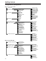
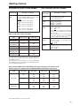
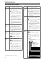
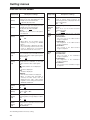
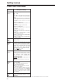
Panasonic Broadcast
AG-DVX100A
Menu Information
Setting menus
Configuration of setting menus
Menus in the camera mode
SCENE FILE
CAMERA SETUP
SYNCRO SCAN
ASPECT CONV
COLOR BAR
SETUP
SW MODE
MID GAIN
HIGH GAIN
ATW
HANDLE ZOOM
IRIS DIAL
USER1
USER2
USER3
AUTO SW
A. IRIS
AGC
ATW
AF
RECORDING SETUP
DISPLAY SETUP
ZEBRA DETECT 1
ZEBRA DETECT 2
MARKER
VIDEO OUT OSD
DATE/TIME
LEVEL METER
ZOOM•FOCUS
TAPE•BATTERY
OTHER DISPLAY
LCD BACKLIGHT
LCD SET
EVF SET
SELF SHOOT
EVF MODE
EVF COLOR
OTHER FUNCTIONS
END SEARCH
32K(12bit)AUDIO
AUDIO OUT
RECORDING SETUP
AV IN/OUT SETUP
A DUB INPUT
DV OUT
DISPLAY SETUP
DATE/TIME
LEVEL METER
TAPE•BATTERY
OTHER DISPLAY
VIDEO OUT OSD
CAMERA DATA
LCD BACKLIGHT
LCD SET
EVF SET
EVF MODE
OTHER FUNCTIONS
40
REC SPEED
AUDIO REC
MIC ALC
MIC GAIN 1
MIC GAIN 2
TC MODE
TCG
FIRST REC TC
TC PRESET
UB MODE
UB PRESET
INTERVAL REC
REC TIME
INTERVAL TIME
REMOTE
DV CONTROL
DV CMD SEL
REC LAMP
BEEP SOUND
CLOCK SET
TIME SHIFT
TAPE PROTECT
USER FILE
HOUR METER
Menus in the VCR mode
PLAYBACK FUNCTIONS
DETAIL LEVEL
V DETAIL LEVEL
DETAIL CORING
CHROMA LEVEL
CHROMA PHASE
COLOR TEMP
MASTER PED
A. IRIS LEVEL
GAMMA
KNEE
MATRIX
SKIN TONE DTL
V DETAIL FREQ
PROGRESSIVE
NAME EDIT
SAVE/INIT
REC SPEED
AUDIO REC
1394 TC REGEN
TC MODE
TCG
FIRST REC TC
TC PRESET
1394 UB REGEN
UB MODE
UB PRESET
REMOTE
CLOCK SET
TIME SHIFT
USER FILE
HOUR METER
Setting menus
SCENE FILE screen
Item/
(display mode)
Description of settings
DETAIL LEVEL
(Camera)
For adjusting the detail amount.
–7 --- 0 --- +7
V DETAIL
(Camera)
For adjusting the strength of the outline
compensation in the vertical direction of the
images.
–7 --- 0 --- +7
DTL CORING
(Camera)
For adjusting the level at which the noise in
the detail signals is to be eliminated.
–7 --- 0 --- +7
When this is adjusted in the “–” direction,
clearer images are produced but the noise
increases slightly.
When it is adjusted in the “+” direction, the
noise decreases.
Item/
(display mode)
GAMMA
(Camera)
CHROMA LEVEL For adjusting the chroma level.
(Camera)
–7 --- 0 --- +7
CHROMA
For finely adjusting the chroma phase.
PHASE (Camera) –7 --- 0 --- +7
COLOR TEMP
(Camera)
For finely adjusting the color temperature
(for performing fine adjustments after the
white balance has been adjusted).
–7 --- 0 --- +7
MASTER PED
(Camera)
For adjusting the black master pedestal
which serves as the video reference.
–15 --- 0 --- +15
A. IRIS LEVEL
(Camera)
For setting the auto iris target value.
–4 --- 0 --- +4
The underlining indicates the factory setting.
Description of settings
For selecting the gamma curve.
LOW:
Using a gamma curve with a moderate
gradient for the low-luminance areas, the
images are given a calm, composed look.
A sharp touch is conveyed by the contrast.
NORM:
Standard images are produced.
HIGH:
Using a gamma curve with a sharp
gradient for the low-luminance areas, the
gradations of the dark areas are
extended to make them appear brighter.
A soft touch is conveyed by the contrast.
B.PRESS:
Images giving the sense of a sharper contrast
than at the LOW setting are produced.
CINE-LIKE:
The gamma curve which gives the
images a cinema-like finish is used.
Images with less noise than at the
CINE_LIKE_D setting are produced.
CINE-LIKE_D:
The dynamic range is higher than at the
CINELIKE setting.
CINE-LIKE_V:
This uses the gamma curve for finishing
the images into movie-like images where
priority is given to contrast.
In order to make full use of the CINELIKE gamma characteristics, it is
recommended that the lens iris be set
lower (by approx. 1/2) than the regular
video level.
KNEE
(Camera)
For setting the level (knee point) at which
the high-brightness video signals sensed by
the CCD are to be compressed in order to
minimize color saturation in the highlights of
the image.
AUTO: The knee point is set automatically in
accordance with the signals sensed.
LOW: The knee point is set on the low side
(with compression starting from
around 80%).
MID: The knee point is set at an interim
value (with compression starting from
around 90%).
HIGH: The knee point is set on the high side
(with compression starting from
around 100%).
MATRIX
(Camera)
For selecting the matrix table and
expressing the colors during shooting.
NORM:
Colors suited to shooting outdoors
or under light sources using
halogen lamps are expressed.
ENRICHED: More vivid colors are expressed
than with the NORM setting.
FLOU:
Colors suited to shooting indoors
under fluorescent light sources
are expressed.
CINE-LIKE: Colors suited to cinema-like
shooting are expressed.
41
Setting menus
SCENE FILE screen
Item/
(display mode)
Description of settings
SKIN TONE DTL
(Camera)
For switching the skin tone detail ON or
OFF.
When ON is selected, the detail in the skin
tone areas is diminished and the graininess
of the skin is reduced.
OFF
ON
V DETAIL FREQ
(Camera)
For setting the detail in the vertical direction
when shooting in the progressive mode.
THIN : The detail is made finer.
MID : The detail is made somewhat coarser.
THICK : The detail is made coarser.
O When “THIN” or “MID” has been selected
as the item’s setting and the images shot
in the progressive mode are played back
using a standard TV monitor (60i:
interlace), some flickering will occur on
the horizontal lines and on the diagonal
lines near the horizontal.
When playing back a tape in a
progressive environment, this flickering
is reduced by selecting “THIN” or “MID”
as the item’s setting, which will also
enable images with a higher resolution
than that with the “THICK” setting to be
obtained.
PROGRESSIVE
(Camera)
For setting shooting in the progressive
mode.
OFF:
Shooting is not performed in the
progressive mode.
30P:
Shooting is performed in the 30P mode
(30 frames/sec.).
24P:
Shooting is performed in the 24P mode
(24 frames/sec.).
Images are recorded on the tape using
the [2:3] conversion system.
24P(ADV):
Shooting is performed in the 24P
advanced mode (24 frames/sec.).
Images are recorded on the tape using
the advanced conversion system.
NAME EDIT
(Camera)
For editing the name of the scene file
selected by the scene file dial.
SAVE/INIT
(Camera)
SAVE:
For saving the scene file settings after
changes have been made to them.
O If the menu mode is released without
saving the changes, the original scene
file settings will be restored when
operation is switched to the VCR mode
or the power is turned off.
INITIAL:
For returning the scene file settings
selected by the scene file dial to the factory
settings.
The underlining indicates the factory setting.
42
CAMERA SETUP screen
Item/
(display mode)
Description of settings
SYNCRO SCAN
(Camera)
For adjusting the shutter speed of synchro
scan used when shooting TV screens, etc.
If the OPERATION lever is left tilted in the
3 or 4 direction, the speed at which the
setting changes is increased, and a beep is
heard.
O Progressive mode OFF:
1/60.3 --- 1/250.0
O Progressive mode 30P:
1/30.1 --- 1/48.0 --- 1/250.0
O Progressive mode 24P or 24PA:
1/24.1 --- 1/48.0 --- 1/250.0
ASPECT CONV
(Camera)
For selecting the aspect ratio of the images
to be recorded.
NORM:
The images are recorded in the standard
4:3 mode.
LETTER BOX:
The aspect ratio is set to the 16:9 mode,
and the images are recorded in this
mode. Black bands are recorded at the
top and bottom of the screen.
SQUEEZE:
The camera images are compressed
horizontally so that they will be displayed
optimally on a 16:9 monitor.
<Note>
The images appearing in the viewfinder and
on the LCD monitor may be disrupted for a
moment when SQUEEZE is selected as the
item setting; this is normal and not
indicative of malfunctioning.
COLOR BAR
(Camera)
For setting the color bar display to ON or
OFF.
OFF
ON
O Even when the color bar display has
been set to ON, it will return to OFF
when operation is switched to the VCR
mode or the power is turned off.
SETUP
(Camera)
For setting whether to add the setup level
(black level).
0%:
The setup level is not added.
7.5%:
The 7.5% setup level is added for
recording.
Setting menus
SW MODE screen
Item/
(display mode)
Description of settings
MID GAIN
(Camera)
For setting the gain value which is to be
allocated to the M position of the GAIN
switch.
0 dB, 3 dB, 6 dB, 9 dB, 12 dB
HIGH GAIN
(Camera)
For setting the gain value which is to be
allocated to the H position of the GAIN
switch.
0 dB, 3 dB, 6 dB, 9 dB, 12 dB
ATW
(Camera)
For setting the ATW (Auto Tracking White)
function which is to be allocated to the
WHITE BAL switch.
OFF:
The ATW function is not activated.
However, if it has been set in the AUTO
button or USER button, it will follow the
operation of the button concerned.
Ach:
The ATW function is activated when the
WHITE BAL switch has been set to the A
position.
Bch:
The ATW function is activated when the
WHITE BAL switch has been set to the B
position.
PRE:
The ATW function is activated when the
WHITE BAL switch has been set to the
PRST position.
HANDLE ZOOM
(Camera)
For setting the zoom speeds which are to
be allocated to the positions of the
HANDLE ZOOM switch.
L/OFF/H:
LOW/OFF/HIGH are set to the 1/2/3
positions. (At OFF, no zoom operations
are performed.)
L/M/H:
LOW/MID/HIGH are set to the 1/2/3
positions.
IRIS DIAL
(Camera)
For setting the rotational direction of the
IRIS dial and iris control (in the MANUAL
IRIS mode).
DOWN OPEN:
The iris opens when the IRIS dial is
turned downward.
UP OPEN:
The iris opens when the IRIS dial is
turned upward.
Item/
(display mode)
Description of settings
USER1
(Camera)
For setting the operation of the function
allocated to the USER1 button.
COLOR BAR:
The color bar display is set to ON or OFF.
SPOTLIGHT:
The auto iris control for the spotlight is
set to ON or OFF.
BACKLIGHT:
The auto iris control for backlight
compensation is set to ON or OFF.
BLACKFADE:
When the button is held down, the whole
image is faded out into black. The sound
is also faded out at the same time.
WHITEFADE:
When the button is held down, the whole
image is faded out into white. The sound
is also faded out at the same time.
MODECHECK:
When the button is pressed, the camera
status currently set is displayed in the
viewfinder and on the LCD monitor
where it can be checked.
ATW:
The operation of the ATW function is set
to ON or OFF.
ATWLOCK:
When the button is pressed, the white
balance value is fixed; when it is pressed
again, the operation of the ATW function
is performed.
GAIN:18 dB:
When this button is pressed, the gain is
set to 18 dB.
O The picture may be temporarily
disturbed when the gain has been
switched to 18 dB or from 18 dB to
another value.
INDEX:
When the button is pressed during
shooting or recording, an index signal is
recorded on the tape. If it is pressed while
shooting or recording is temporarily
stopped, the index signal recording
standby mode is established. When
shooting or recording is commenced from
this mode, the index signal will be recorded
on the tape. Recording index signals
enables index searches to be performed
during playback. (See page 63)
SLOWSHUT:
When the button is pressed, the slow
shutter mode is established. Each time
it is pressed, the mode is turned ON or
OFF alternatively.
USER2
(Camera)
For setting the operation of the function to
be allocated to the USER2 button.
The settings are the same as for the ones
for the USER1 items.
BACKLIGHT
USER3
(Camera)
For setting the operation of the function to
be allocated to the USER3 button.
The settings are the same as for the ones
for the USER1 items.
INDEX
The underlining indicates the factory setting.
43
Setting menus
AUTO SW screen
Item/
(display mode)
Description of settings
A. IRIS
(Camera)
ON:
When the AUTO button is pressed, the
auto iris control operation is performed.
The IRIS button does not work at this
time.
OFF:
The auto iris control operation is not
performed even if the AUTO button is
pressed.
The iris control operation selected by the
IRIS button is performed.
AGC
(Camera)
For setting the auto gain control operation
when ON is selected as the A. IRIS item
setting.
6 dB:
Auto gain control up to 6 dB is performed
when the AUTO button is pressed.
12 dB:
Auto gain control up to 12 dB is
performed when the AUTO button is
pressed.
OFF:
Auto gain control is not performed even
if the AUTO button is pressed.
ATW
(Camera)
ON:
The ATW (auto tracking white balance)
function operation is set to ON or OFF
using the AUTO button.
At this time, the operation of this function
cannot be set to ON or OFF using the
WHITE BAL switch and USER button.
However, when ATWLOCK is allocated
to the USER button, the white balance
value can be fixed using the USER
button.
OFF:
The ATW function operation is not
performed even if the AUTO button is
pressed.
The ATW function operation selected by
the WHITE BAL switch is performed.
AF
(Camera)
ON:
When the AUTO button has been
pressed, the auto focus operation is
performed.
The FOCUS switch and PUSH AUTO
button do not work at this time.
OFF:
The auto focus operation is not
performed even if the AUTO button is
pressed.
The focus operation selected by the
FOCUS switch and PUSH AUTO button
is performed.
The underlining indicates the factory setting.
44
PLAYBACK FUNCTIONS screen
Item/
(display mode)
Description of settings
END SEARCH
(VCR)
For setting what kind of operation is to be
performed when the EVF DTL/END
SEARCH button is pressed.
BLANK:
The unrecorded blanks on the video tape
are searched.
REC END:
The part which was shot last is
searched.
<Notes>
O Even when the REC END setting is
selected, the part which was shot last
will not be searched when the tape is
switched.
O If nothing has been recorded on the
tape, operation will stop at the end of the
tape.
O END SEARCH may not operate properly
if there is an unrecorded blank near the
tape start or at a point along the tape.
32K (12bit)
AUDIO
(VCR)
For setting the sound to be output as the
CH1 and CH2 signals when a tape
recorded in the 32K (12-bit) audio mode is
played back.
ST1:
The sound recorded during shooting is
selected.
CH1 signals = CH1 track
CH2 signals = CH2 track
ST2:
The sound recorded during audio
dubbing is selected.
CH1 signals = CH3 track
CH2 signals = CH4 track
MIX:
The sound recorded during shooting and
the sound recorded during audio
dubbing are mixed.
CH1 signals = CH1 + CH3 tracks
CH2 signals = CH2 + CH4 tracks
<Note>
If the sound has been recorded in the 48K
(16-bit) mode, there is no CH3 or CH4.
Therefore, the correlation between the
signals and tracks will always be as follows:
CH1 signals = CH1 track
CH2 signals = CH2 track
Setting menus
PLAYBACK FUNCTIONS screen
Item/
(display mode)
AUDIO OUT
(VCR)
Description of settings
For setting the audio signals to be output
from the AUDIO IN/OUT connectors (pin
jacks) when a tape is played back.
CH1•CH2:
CH1 connector = CH1 signals
CH2 connector = CH2 signals
CH1:
CH1 connector = CH1 signals
CH2 connector = CH1 signals
CH2:
CH1 connector = CH2 signals
CH2 connector = CH2 signals
RECORDING SETUP screen
Item/
(display mode)
REC SPEED
(Camera)
(VCR)
For selecting the recording time mode.
SP : SP (standard play) mode
LP : LP (long play) mode
AUDIO REC
(Camera)
(VCR)
For selecting the system for converting the
recording to PCM audio.
32K(12 bit) : 12-bit/32kHz
48K(16 bit) : 16-bit/48kHz
MIC ALC
(Camera)
For setting the mic level automatic control
function to ON or OFF.
OFF
ON
Audio distortion caused by excessively high
input level can be minimized by selecting
ON for this item.
O The recording level of the audio signals
must be adjusted using the AUDIO
controls, irrespective of this setting.
MIC GAIN 1
(Camera)
For setting the input level of the external
microphone which is connected to the
INPUT 1 connector.
-50 dB -60 dB
MIC GAIN 2
(Camera)
For setting the input level of the external
microphone which is connected to the
INPUT 2 connector.
-50 dB -60 dB
Inputs and audio tracks recorded
Input
When shooting
When audio dubbing
(12-bit mode)
Internal
microphone L
CH1
CH3
Internal
microphone R
CH2
CH4
INPUT 1 (XLR)
CH1
CH3
INPUT 2 (XLR)
CH2 (CH1)
CH4 (CH3)
AUDIO IN/OUT
CH1 (pin jack)
__
CH3
AUDIO IN/OUT
CH2 (pin jack)
__
CH4
Description of settings
The audio tracks on which signals are to be recorded during
shooting can be changed using the CH1 SELECT switch and
CH2 SELECT switch.
The audio tracks on which signals are to be recorded during
audio dubbing can be changed using the A DUB INPUT item
on the AV IN/OUT SETUP screen.
32K (12-bit) AUDIO item and AUDIO OUT item settings, and audio tracks
whose signals are output from the AUDIO IN/OUT connectors (pin jacks)
Audio recording
mode
32K (12-bit) AUDIO
item setting
AUDIO OUT
item setting
AUDIO IN/OUT
CH1 output
AUDIO IN/OUT
CH2 output
ST1
CH1•CH2
CH1
CH2
CH1
CH1
CH2
CH2
CH1
CH2
ST2
CH1•CH2
CH1
CH2
CH3
CH3
CH4
CH4
CH3
CH4
MIX
__
CH1+CH3
CH2+CH4
__
CH1•CH2
CH1
CH2
CH1
CH1
CH2
CH2
CH1
CH2
32K (12 bit)
48K (16 bit)
The underlining indicates the factory setting.
45
Setting menus
RECORDING SETUP screen
Item/
(display mode)
1394 TC REGEN
(VCR)
TC MODE
(Camera)
(VCR)
Description of settings
For selecting the time code to be recorded
when recording the signals of a component
connected to the DV connector.
OFF:
The signals are recorded using the time
code which was set using the TC MODE
item, TCG item and FIRST REC TC
item.
ON:
The signals are recorded using the time
code of the signals which have been
input to the DV connector.
O When ON has been selected as this
item’s setting, this setting takes
precedence over the TC MODE item,
TCG item and FIRST REC TC item
settings.
O When no signals are supplied to the DV
connector, the TC MODE item, TCG item
and FIRST REC TC item settings are
followed.
For selecting the time code correction
mode in which the time code of the internal
time code generator is to be recorded.
DF : The drop frame mode is used.
NDF : The non-drop frame mode is used.
O When the progressive mode has been
set to 24P or 24P (ADV), the non-drop
frame mode is established regardless of
this item’s setting.
TCG
(Camera)
(VCR)
For setting the operation mode in which the
internal time code generator is to be run.
FREE RUN:
The internal time code generator is run
regardless of the operation mode.
REC RUN:
The internal time code generator is run
during recording.
FIRST REC TC
(Camera)
(VCR)
For selecting the time code which is to be
recorded when recording is started.
REGEN:
Recording proceeds in such a way that
the time code continues on (is
regenerated) from the time code on the
tape.
PRESET:
The time code is not regenerated from
the time code on the tape.
The time code is recorded using the
value set in the TC PRESET item
serving as the initial value.
However, the time code is forcibly
regenerated when shooting with frameto-frame continuity has been performed.
Item/
(display mode)
Description of settings
TC PRESET
(Camera)
(VCR)
For setting the initial value of the time code
to be recorded.
This item’s setting is valid when PRESET
has been selected as the setting for the
FIRST REC TC item.
O When the progressive mode has been
set to 24P or 24P (ADV), set the frame
value to 0 or to a multiple of 5. If any
other value is set, the time code
recorded will shift.
1394 UB REGEN
(VCR)
For selecting the user’s bit to be recorded
when recording the signals of the
component connected to the DV connector.
OFF:
The user’s bit selected for the UB MODE
item is used for the recording.
ON:
The user’s bit of the signals input to the
DV connector is used for the recording.
O When ON has been selected as this item’s
setting, this setting takes precedence over
the UB MODE item setting.
O The user’s bit is not recorded if the
signals do not contain the user’s bit
information.
O When no signals are supplied to the DV
connector, the UB MODE item setting is
followed.
UB MODE
(Camera)
(VCR)
For setting what is to be recorded as the
user’s bit.
USER:
The user’s information is recorded.
TIME:
The time of the recording is recorded.
DATE:
The date of the recording is recorded.
TCG:
The time code generator’s value is
recorded.
FRM. RATE:
The frame rate information for frame
conversion is recorded.
22 02 22 22
Recording control
information
O Updated frame information
O REC START/STOP
information
Frame rate information
O Frame rate (60, 30 or 24)
O I/P identification information
O Conversion information
O Frame rate coefficient
Frame sequence number
O A number from 0 to 4 is displayed
in the 24P or 24P (ADV) mode.
O “F” is displayed in the 60 or 30P
mode.
The underlining indicates the factory setting.
46
User’s bit value verification
information
Setting menus
RECORDING SETUP screen
Item/
(display mode)
Description of settings
UB PRESET
(Camera)
(VCR)
For setting the user’s bit. However, USER
must be selected for the UB MODE item
setting.
INTERVAL REC
(Camera)
For setting the intermittent recording mode.
OFF: Intermittent recording is not performed.
ON: When the START/STOP button is
pressed, intermittent recording is
performed with the cycle set by the REC
TIME item and INTERVAL TIME item.
ONE-SHOT: The time lapse shooting mode is
established.
When the START/STOP button is
pressed, recording is performed for the
number of seconds set by the REC TIME
item, after which the recording pause
mode is established.
O When intermittent recording is set to ON or
ONE-SHOT, “I –” flashes on the left of the
VCR operation mode. When recording is
started, it stops flashing and lights.
O Even when intermittent recording is set to
ON or ONE-SHOT, the intermittent
recording mode returns to OFF when the
power is turned off.
O When the progressive mode has been
set to 24P or 24P (ADV), the OFF is
established regardless of this item’s
setting.
REC TIME
(Camera)
For setting the recording duration for which
intermittent recording is to be performed.
0.5s: 0.5 sec.
1s : 1.0 sec.
1.5s: 1.5 sec.
2s : 2.0 sec.
INTERVAL TIME
(Camera)
For setting the duration of the interval time
with which intermittent recording is to be
performed.
15s : 15 sec.
30s : 30 sec.
1m : 1 min.
5m : 5 min.
10m : 10 min.
AV IN/OUT SETUP screen
Item/
(display mode)
Description of settings
A DUB INPUT
(VCR)
For selecting the sound which is to be
recorded when audio dubbing is performed.
MIC: The sound from the internal microphone
or the sound from the external
components connected to the INPUT 1
and 2 connectors is recorded. (The
sound is selected using the CH1 SELECT
switch and CH2 SELECT switch.)
A_IN: The sound of the audio component
connected to the AUDIO IN/OUT
connectors (pin jacks) is recorded.
<Note>
If audio dubbing is performed when the
sound has been recorded in the 16-bit
audio mode, the sound will be recorded
over the sound heard during shooting.
DV OUT
(VCR)
For setting the function, which converts the
analog signals which have been input into
digital signals and outputs them from the
DV connector, to ON or OFF.
OFF
ON
The underlining indicates the factory setting.
47
Setting menus
DISPLAY SETUP screen
Item/
(display mode)
Description of settings
ZEBRA DETECT
1
(Camera)
For setting the level of the zebra pattern
leaning to the left and displayed in the
viewfinder and on the LCD monitor.
80%, 85%, 90%, 95%, 100%, 105%
ZEBRA DETECT
2
(Camera)
For setting the level of the zebra pattern
leaning to the right and displayed in the
viewfinder and on the LCD monitor.
80%, 85%, 90%, 95%, 100%, 105%, OFF
<Note>
When OFF has been set, the zebra pattern
is not displayed.
MARKER
(Camera)
For switching display of the marker
ON/OFF.
ON
OFF
O When ON is set, the marker can be
displayed by pressing the ZEBRA
button.
When the marker is displayed, the video
level of the image near the center of the
screen is displayed as a percentage
value at the bottom left of the screen.
VIDEO OUT OSD When ON is set, the information displayed
in the viewfinder and on the LCD monitor is
(Camera)
output as the video output signal together
(VCR)
with the images.
ON
OFF
DATE/TIME
(Camera)
(VCR)
For setting the date and/or time to be
displayed in the viewfinder, on the LCD
monitor and in the video output signals.
OFF:
The date and time are not displayed.
TIME:
The time is displayed.
DATE:
The date is displayed.
TIME&DATE:
Both the date and time are displayed.
O When a setting other than OFF is
selected, the date and/or time are
displayed in the video output signals
regardless of the setting selected for the
VIDEO OUT OSD item.
LEVEL METER
(Camera)
(VCR)
For setting the audio level meter display to
ON or OFF.
OFF
ON
ZOOM•FOCUS
(Camera)
For setting the zoom and focus value
displays to ON or OFF.
OFF
ON
TAPE•BATTERY
(Camera)
(VCR)
For setting the remaining tape amount and
remaining battery charge displays to ON or
OFF.
OFF
ON
OTHER
DISPLAY
(Camera)
(VCR)
For setting the amount of information to be
displayed in the viewfinder and on the LCD
monitor. (See page 57)
OFF, PARTIAL, ALL
The underlining indicates the factory setting.
48
Item/
(display mode)
Description of settings
CAMERA DATA
(VCR)
When ON is set, the camera information
(such as camera shake correction, iris
value and gain value) is displayed when the
tape is played back.
OFF
ON
LCD
BACKLIGHT
(Camera)
(VCR)
For adjusting the backlight of the LCD
monitor.
When HI is set, the monitor becomes
brighter than usual.
HI
NORMAL
LCD SET
(Camera)
(VCR)
For adjusting the display level of the LCD
monitor images.
LCD COLOR LEVEL:
The color level of the LCD monitor’s
images is adjusted.
LCD BRIGHTNESS:
The brightness of the LCD monitor’s
images is adjusted.
LCD CONTRAST:
The contrast of the LCD monitor’s
images is adjusted.
EVF SET
(Camera)
(VCR)
For adjusting the display level of the
viewfinder images.
EVF COLOR LEVEL:
The color level of the viewfinder’s
images is adjusted.
EVF BRIGHTNESS:
The brightness of the viewfinder’s
images is adjusted.
EVF CONTRAST:
The contrast of the viewfinder’s images
is adjusted.
Setting menus
DISPLAY SETUP screen
Item/
(display mode)
Description of settings
SELF SHOOT
(Camera)
For selecting the LCD monitor’s mirror
function for face-to-face shooting. When
MIRROR is set, the image on the LCD
monitor is reversed at the left and right for
display during face-to-face shooting.
NORMAL
MIRROR
EVF MODE
(Camera)
(VCR)
For selecting what is to be displayed in the
viewfinder and on the LCD monitor.
ON:
Images are shown at all times in the
viewfinder.
AUTO:
When the LCD monitor is opened, the
images no longer appear
in the
viewfinder.
EVF COLOR
(Camera)
OTHER FUNCTIONS screen
Item/
(display mode)
Description of settings
REMOTE
(Camera)
(VCR)
For setting the operations which are
performed using the accessory wireless
remote control unit. (See page 20 for the
remote control unit settings.)
VCR1: The operation performed by the
remote control unit which has been set
to be used for VCR1 are accepted.
VCR2: The operation performed by the
remote control unit which has been set
to be used for VCR2 are accepted.
OFF: Operations performed by the remote
control unit are not accepted.
DV CONTROL
(Camera)
For setting the control method when
backup shooting is to be performed by
connecting a component for backup
purposes to the DV connector.
OFF: The component for backup purposes
is not controlled.
EXT: The component for backup purposes
is controlled using the START/STOP
button on the camera recorder. The
images shot by the camera recorder are
recorded by the component for backup
purposes.
However, the camera recorder does not
record the images.
BOTH: The images shot by the camera
recorder are recorded by both camera
recorder and the component for backup
purposes.
CHAIN: When the tape in the camera
recorder approaches the end during
shooting, recording is automatically
commenced by the component for
backup purposes, which has been set to
the recording standby mode.
DV CMD SEL
(Camera)
For setting the recording operation to be
performed by the component for backup
purposes when the START/STOP button
on the camera recorder has been pressed.
REC_P:
The mode is switched between recording
and recording pause.
STOP:
The mode is switched between recording
and stop.
<Note>
Select STOP as the item’s setting if the
component for backup purposes is not
equipped with a recording pause function.
REC LAMP
(Camera)
For setting the lighting of the tally lamps.
OFF: The tally lamps do not light.
FRONT: The front tally lamp (by the
microphone) lights.
REAR: The rear tally lamp (by the
viewfinder) lights.
BOTH: Both the front and rear tally lamps
light.
For selecting color or monochrome for the
viewfinder display.
ON:
Color display
OFF:
Monochrome display
The underlining indicates the factory setting.
49
Setting menus
OTHER FUNCTIONS screen
Item/
(display mode)
BEEP SOUND
(Camera)
Description of settings
For setting the beep tone to ON or OFF.
OFF
ON
When ON is selected as the setting, the
beep tone is sounded at the times given
below.
O When the beep tone is sounded, the
audio signals from the output connectors
are muted, and the beep tone is output
instead.
[Beep tone sounds once]
OWhen the POWER switch has been set
to ON
OWhen shooting has commenced
[Beep tone sounds twice]
OWhen shooting has been temporarily
stopped
[Beep tone sounds 10 times]
OWhen the cassette tape has not been
inserted
OWhen the cassette tape is in the
recording pause mode
OWhen condensation has formed inside
the camera recorder
OWhen a problem has occurred in the
camera recorder
CLOCK SET
(Camera)
(VCR)
For setting the internal calendar of the
camera recorder.
TIME SHIFT
(Camera)
(VCR)
For adding the time which was set using
this item to the time of the internal calendar
(to compensate for time differences) for
display in the viewfinder and on the LCD
monitor. The clock time after the
compensation is also recorded on the tape.
+23h --- +1h, OFF, –1h --- –23h
(In 1-hour increments)
TAPE PROTECT
(Camera)
When the camera recorder is left on
standby for about 5 minutes in the shooting
pause mode, it is automatically set to the
tape protection mode. Which tape
protection mode is to be established is
selected using this item.
POWEROFF: The camera recorder’s power is
set to the OFF mode.
STBY: The cylinder head is set to the stop
mode.
USER FILE
(Camera)
(VCR)
LOAD: The settings stored last in the user
file are loaded.
SAVE: The user file settings which have
been changed are saved.
INITIAL: The user file settings are restored
to the factory settings.
O When the LOAD or INITIAL operation
has been performed, set the POWER
switch on the camera recorder to OFF
and then to ON again in order to enable
the settings.
HOUR METER
(Camera)
(VCR)
For indicating the total rotational time of the
cylinder head (5-digit display in 1-hour
increments).
The underlining indicates the factory setting.
50