1
WS-7013U
Wireless 433 MHz
Temperature Station
Instruction Manual
Register your product
on the web at:
WWW.ORECK.COM
TABLE OF CONTENTS
Topic
Inventory of Contents
Quick Setup
Detailed Setup Guide
Battery Installation
Setting the Time
Selecting Units of
Measurement
Features
Minimum and
Maximum Temperatures
Resetting Minimum and
Maximum Temperatures
Mounting
Troubleshooting
Maintenance and Care
Specifications
Warranty Information
1
Page
2
3-5
5-7
7-8
8
9
9
9-10
10-12
12
13-14
14
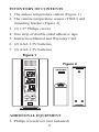
INVENTORY OF CONTENTS
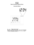
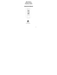
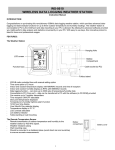
1. The indoor temperature station (Figure 1)
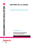
2. The remote temperature sensor (TX6U) and
mounting bracket (Figure 2)
3. (3) 1/2" Philips screws
4. One strip of double sided adhesive tape
5. Instruction Manual and Warranty Card
6. (2) AAA 1.5V batteries
7. (2) AAA 1.5V batteries
Figure 1
Figure 2
ADDITIONAL EQUIPMENT
1. Philips screwdriver (not included)
2
QUICK SETUP
Hint: Use good quality Alkaline Batteries and
avoid rechargeable batteries.
1. Have the indoor temperature station and
remote temperature sensor 3 to 5 feet apart.
2. Batteries should be out of both units for 10
minutes.
3. Place the batteries into the remote temperature
sensor first then into the indoor temperature
station.
(All remote temperature sensors must be
started before the indoor temperature station)
4. DO NOT PRESS ANY BUTTONS FOR
10 MINUTES.
In this time the indoor temperature station and
remote temperature sensor will start to talk to each
other and the display will show both the indoor
and outdoor temperature. If the indoor
temperature station does not display both
temperatures after the 10 minutes please retry the
set up as stated above. After both the indoor and
outdoor temperatures are displayed for 10 minutes
you can place your remote temperature sensor
outdoors and set the time.
The remote temperature sensor has a range of
80 feet and should be placed in a dry, shaded area.
3
Any walls the signal will have to pass through
will reduce distance. An outdoor wall or window
will have 20 to 30 feet of resistance and an interior
wall will have 10 to 20 feet of resistance. Your
distance plus resistance should not exceed
80 feet in a straight line.
NOTE: Fog and mist will not harm your
remote temperature sensor, but direct rain must
be avoided. To complete the setup of your indoor
temperature station after the 10 minutes have
passed, please follow the steps below:
1. To set the time, press and hold the "SET"
button for 5 seconds.
Note: A "12h" or "24h" will appear on the top
line. ("12h" for AM/PM, "24h" for military
time)
a. To change between "12h" and "24h" press
and release the "MIN/MAX" button.
b. When you have your choice shown on the
display press and release the "SET" button
once.
2. Degrees Fahrenheit will now show.
a. To change between Fahrenheit and Celsius,
press and release the "MIN/MAX" button.
b. When you have your choice shown on the
display press and release the "SET" button
once.
4
3. The hour will now be flashing.
a. Press and release the "MIN/MAX" button
until the correct hour is shown.
Note: When in the 12h mode "PM" is
displayed under the word "TIME" during PM
hours. During the AM hours this area will be
blank.
b. When the correct hour is shown, press and
release the "SET" button once.
4. The minutes will now be flashing.
a. Press and release the "MIN/MAX" button
until the correct minutes are displayed.
Press and release the SET button once
more to complete the setup.
DETAILED SETUP GUIDE
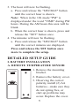
I. BATTERY INSTALLATION
A. REMOTE TEMPERATURE SENSOR
1. Remove the mounting
bracket.
2. Remove the battery cover.
3. Observing the correct
polarity, install (2) AA
batteries—make sure they
do not spring free, or
start-up problems may
occur. Replace the cover.
5
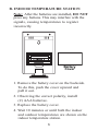
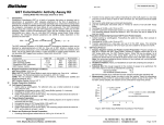
B. INDOOR TEMPERATURE STATION
Note: After the batteries are installed, DO NOT
press any buttons. This may interfere with the
signals, causing temperatures to register
incorrectly.
Battery
Cover
1. Remove the battery cover on the backside.
To do this, push the cover upward and
pull it out.
2. Observing the correct polarity, install
(2) AAA batteries.
3. Replace the battery cover.
4. Wait 10 minutes or until both the indoor
and outdoor temperatures are shown on the
indoor temperature station.
6
5. The indoor temperature station should now
show: "-:- -" in the TIME LCD, and
temperatures in the INDOOR and
OUTDOOR LCD’s.
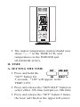
II. TIME
A. SETTING THE TIME
1. Press and hold the
"SET" button for
5 seconds, "12h" will appear in the
TIME LCD.
2. Press and release the "MIN/MAX" button to
select either 12h time (am/pm) or 24h time.
3. Press and release the "SET" button 2 times,
the hour will flash in the upper left corner.
7
4. Press and release the "MIN/MAX" button to
set the hour.
5. Press and release the "SET" button to move
to the minute setting.
6. Press and release the "MIN/MAX" button
to set the minutes.
7. Press and release the "SET" button to
activate the clock.
Note: When in 12h mode, there is only a
"PM" display, which appears under "TIME."
If there is no display, then it is in AM mode.
Make sure you set the time accordingly.
III. UNITS OF TEMPERATURE MEASURE
A. SELECTING UNITS OF MEASUREMENT
1. Press and hold the "SET" button for
5 seconds until "12h" or "24h" appears in
the TIME LCD.
2. Press and release the "SET" button again,
"°F" will appear in the TIME LCD.
3. Press and release the "MIN/MAX" button
to shift between °F and °C.
4. Press and release the "SET" button twice to
activate settings.
8
IV. FEATURES
A. MINIMUM AND MAXIMUM
TEMPERATURES
1. Press and release the "MIN/MAX" button.
"MIN" appears in the temperature LCDs and
the recorded minimum temperatures are
displayed.
2. Press and release the "MIN/MAX" button to
toggle to the maximum temperatures. The
time of occurrence of the value for outdoor
temperature will also flash.
B. RESETTING THE MINIMUM AND
MAXIMUM TEMPERATURES
1. To reset both the minimum and maximum
temperatures—press and hold the "RESET/+"
button for 4 seconds.
V. MOUNTING
Note: To achieve a true temperature reading,
avoid mounting in direct sunlight. We
recommend that you mount the remote
temperature sensor on an outside North-facing
wall. The sending range is 80 feet; obstacles
such as walls, concrete, and large metal objects
will reduce the range. Test the system by
placing both units in their desired location
9
before permanently mounting.
A. REMOTE TEMPERATURE SENSOR
1. Remove the mounting bracket from the
remote temperature sensor.
2. Mount using either screws or adhesive tape.
3. Reattach the remote temperature sensor to
the mounting bracket.
B. THE TEMPERATURE STATION
1. The indoor temperature station comes with
the table stand already mounted. If you
wish to use the table-stand, all that is
required is to place the indoor temperature
station in an appropriate location.
2. To wall mount, remove the table stand. To
do this, pull down on the stand from the
rear and rotate forward.
a) Fix a screw (not included) into the
desired wall, and place the indoor
temperature station onto the screw using
the hanging hole on the backside.
Gently pull the indoor temperature
station down to lock the screw into place.
TROUBLESHOOTING
NOTE: For problems not solved, please
contact Oreck Customer Service at
1-800-989-3535.
10
Problem: The LCD is faint
Solution: Replace batteries
Problem: No outdoor temperature is displayed.
Solution:
1) Remove all batteries, reinsert into remote
temperature sensor first, and then into the
indoor temperature station.
2) Place remote temperature sensor closer to the
indoor temperature station.
3) Make sure all batteries are new.
4) Place remote temperature sensor and indoor
temperature station in position so the
straight-line signal is not passing through
more than two or three walls.
Problem: Temperatures do not match if units are
placed next to each other.
Solution: Each temperature sensor is manufactured
to be accurate, under normal conditions, to
within 1 degree plus or minus and; so two
temperature sensors could be as much as 2
degrees different. However, the difference can
be exaggerated further because the temperature
sensors are designed for different working
environments. The indoor sensor is less
11
responsive to ambient air currents because of
the shielding effect of the display case. In
addition, the case can act as a heat sink to
absorb and store heat from external sources
(i.e. handling of the case or radiant heat). In
addition, the much greater range of the
outdoor temperature sensor requires a
different calibration curve than the indoor
range. Error is usually greater at the extreme
ends of a range, making it harder to compare
different ranges with different curves. Under
non-laboratory conditions, it is difficult to
compensate for the above factors and obtain
an accurate comparison.
MAINTENANCE AND CARE INSTRUCTIONS
●
Extreme temperatures, vibration, and shock
should be avoided to prevent damage to the
units.
●
Clean displays and units with a soft, damp
cloth. Do not use solvents or scouring agents;
they may scratch the displays and casings.
●
Do not submerge in water.
●
Do not subject the units to unnecessary heat or
cold by placing them in the oven or freezer.
●
Opening the casings voids the warranty. Do
not try to repair the unit.
12
SPECIFICATIONS
Transmitting
433MHz
Frequency
Measuring Temperatures
Indoor Temperature 32°F to 156.2°F with
Station: Indoor
0.2°F resolution.
(0°C to 69.0°C with
0.1°C resolution)
Remote Temperature -21.8 °F to 156.2°F
Sensor: Outdoor
0.2°F resolution.
(-29.9°C to 69.0°C with
0.1°C resolution)
Temp accuracy
+/- 1°F (+/- .5°C)
Transmitting range
Maximum 80 feet
(25m) open space
Temperature check
Indoor
Every 10 seconds
Outdoor
Three times in
10 minutes
Batteries—(Alkaline recommended)
Remote Temperature 2 x AA, 1.5V
Sensor
Indoor Temperature 2 x AAA, 1.5V
Station
Dimensions: (L x W x H)
Indoor Temperature 2.75 x .92 x 4.3 in.
Station
(excluding table stand)
(90 x 23.6 x 110 mm)
13
Remote Temperature
Sensor
Battery life
1.57" x 0.9" x 5.04"
(40 x 23 x 128 mm)
Approximately 1 year
WARRANTY INFORMATION
Oreck Corporation warrants the Indoor/Outdoor
Clock and Weather Station (WS-7013U) free
from defects in material and workmanship under
normal, non-commercial use and service. Oreck
will remedy any such defects if they appear within
one (1) year from date of purchase. This warranty
gives you specific legal rights, and you may have
other rights, which vary, from state to state.
FCC ID: OMO-01RX (Receiver),
OMO-01TX (transmitter)
THIS DEVICE COMPLIES WITH PART 15
OF THE FCC RULES. OPERATION IS
SUBJECT TO THE FOLLOWING TWO
CONDITIONS:
1. THIS DEVICE MAY NOT CAUSE
HARMFUL INTERFERENCE.
2. THIS DEVICE MUST ACCEPT
INTERFERENCE RECEIVED,
INCLUDING INTERFERENCE THAT
MAY CAUSE UNDESIRED OPERATION.
14
©2002 Oreck Holdings, LLC. All rights reserved.