1
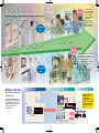
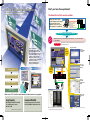
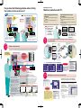
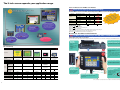
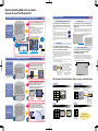
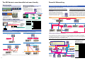
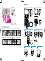
Read and Understand this Catalog
Please read and understand this catalog before purchasing the product. Please consult your OMRON representative if you have any
questions or comments.
Warranty and Limitations of Liability
WARRANTY
NS12-V2 NS10-V2
NS8-V2
10-inch Model
8-inch Model
NS5-V2
NSH5
5-inch Model
5-inch Hand-held Model
12-inch Model
OMRON's exclusive warranty is that the products are free from defects in materials and workmanship for a period of one year (or
other period if specified) from date of sale by OMRON.
OMRON MAKES NO WARRANTY OR REPRESENTATION, EXPRESS OR IMPLIED, REGARDING NON-INFRINGEMENT,
MERCHANTABILITY, OR FITNESS FOR PARTICULAR PURPOSE OF THE PRODUCTS. ANY BUYER OR USER ACKNOWLEDGES THAT
THE BUYER OR USER ALONE HAS DETERMINED THAT THE PRODUCTS WILL SUITABLY MEET THE REQUIREMENTS OF THEIR
INTENDED USE. OMRON DISCLAIMS ALL OTHER WARRANTIES, EXPRESS OR IMPLIED.
LIMITATIONS OF LIABILITY
OMRON SHALL NOT BE RESPONSIBLE FOR SPECIAL, INDIRECT, OR CONSEQUENTIAL DAMAGES, LOSS OF PROFITS OR
COMMERCIAL LOSS IN ANY WAY CONNECTED WITH THE PRODUCTS, WHETHER SUCH CLAIM IS BASED ON CONTRACT,
WARRANTY, NEGLIGENCE, OR STRICT LIABILITY.
In no event shall the responsibility of OMRON for any act exceed the individual price of the product on which liability is asserted.
IN NO EVENT SHALL OMRON BE RESPONSIBLE FOR WARRANTY, REPAIR, OR OTHER CLAIMS REGARDING THE PRODUCTS
UNLESS OMRON'S ANALYSIS CONFIRMS THAT THE PRODUCTS WERE PROPERLY HANDLED, STORED, INSTALLED, AND
MAINTAINED AND NOT SUBJECT TO CONTAMINATION, ABUSE, MISUSE, OR INAPPROPRIATE MODIFICATION OR REPAIR.
Programmable Terminals
NS-CXDC1-V1
Ver. 1
NS-series Screen Creation Software
Installing a Navigator: A Totally New Concept in
Programmable Terminals
Application Considerations
SUITABILITY FOR USE
OMRON shall not be responsible for conformity with any standards, codes, or regulations that apply to the combination of the
product in the customer's application or use of the product.
Take all necessary steps to determine the suitability of the product for the systems, machines, and equipment with which it will be
used.
Know and observe all prohibitions of use applicable to this product.
NEVER USE THE PRODUCT FOR AN APPLICATION INVOLVING SERIOUS RISK TO LIFE OR PROPERTY WITHOUT ENSURING THAT
THE SYSTEM AS A WHOLE HAS BEEN DESIGNED TO ADDRESS THE RISKS, AND THAT THE OMRON PRODUCT IS PROPERLY
RATED AND INSTALLED FOR THE INTENDED USE WITHIN THE OVERALL EQUIPMENT OR SYSTEM.
PROGRAMMABLE PRODUCTS
OMRON shall not be responsible for the user's programming of a programmable product, or any consequence thereof.
Disclaimers
CHANGE IN SPECIFICATIONS
Product specifications and accessories may be changed at any time based on improvements and other reasons. Consult with your
OMRON representative at any time to confirm actual specifications of purchased product.
DIMENSIONS AND WEIGHTS
Dimensions and weights are nominal and are not to be used for manufacturing purposes, even when tolerances are shown.
PERFORMANCE DATA
Performance data given in this catalog is provided as a guide for the user in determining suitability and does not constitute a
warranty. It may represent the result of OMRON's test conditions, and the users must correlate it to actual application requirements.
Actual performance is subject to the OMRON Warranty and Limitations of Liability.
Note: Do not use this document to operate the Unit.
OMRON Corporation
Control Devices Division H.Q.
Shiokoji Horikawa, Shimogyo-ku,
Kyoto, 600-8530
Japan
Tel:(81)75-344-7109
Fax:(81)75-344-7149
OMRON ELECTRONICS LLC
1 East Commerce Drive, Schaumburg,
IL 60173 U.S.A.
Tel:(1)847-843-7900/Fax:(1)847-843-8568
Regional Headquarters
OMRON ASIA PACIFIC PTE. LTD.
83 Clemenceau Avenue,
#11-01, UE Square,
Singapore 239920
Tel:(65)6835-3011/Fax: (65)6835-2711
OMRON EUROPE B.V.
Wegalaan 67-69, NL-2132 JD Hoofddorp
The Netherlands
Tel:(31)2356-81-300/
Fax:(31)2356-81-388
OMRON (CHINA) CO., LTD.
Room 2211, Bank of China Tower,
200 Yin Cheng Zhong Road,
PuDong New Area, Shanghai, 200120 China
Tel:(86)21-5037-2222/Fax:(86)21-5037-2200
Printed on 100%
Recycled Paper
Authorized Distributor:
Note: Specifications subject to change without notice.
Cat. No. V078-E1-09
Printed in Japan
0206-1M
NSH5
NS5-V2
NS8-V2
NS10-V2
NS12-V2
5-inch
Hand-held
Model
5-inch Model
8-inch Model
10-inch Model
12-inch Model
NS Series
Make it More Simple
Seamless
The NS is moving to the next stage, from a touch screen
to an advanced machine management tool.
It's convenient
but…
We are always trying to
provide solutions that will
give the highest added
value to your system.
We strive to solve on-site
problems with our
solutions instead of just
providing touch screen
functions. That is what
OMRON is focused on.
agement
n
a
M
e
in
h
c
Ma
peration
O
n
e
e
r
c
S
h
Touc
ration
e
p
O
h
c
it
w
S
Smart
Turning switches into Touch Screens brings
enhancements, such as minimum wiring,
space savings, and improved local operation
efficiency. Moreover, OMRON works to
minimize the customer's energy expenditure
from machine design to troubleshooting.
OK!
It's convenient
but…
From PLC Memory Allocation
to Device Access
Previous PTs shared data that was
allocated in advance to specific words in
the CPU Unit, and they were used to
assist with device operations, and to
display error locations, and
countermeasures.
New zone
Previous zone
Previous PT
NS Enters a New Zone
NS Series
PLC
PT
PLC
CPU Unit
Network
Example: DeviceNet
It's time for
switch inspection.
Allocated data
Sharing allocated
data with CPU Unit
Smart Active Parts
(Functional software parts)
Example: Monitoring maintenance information
for various DeviceNet Smart Slave models
2
Special I/O Units
The NS Series achieves
flexible data access to a
variety of devices. It
enables operators to reach
the devices on the network
including Special I/O Units,
intelligent devices, and
PLCs.
The cylinder
speed is strange.
Intelligent devices
Example: DRT2-series Smart Slave
3
PTs as a Machine Navigator
NS-series PTs navigate all areas of machine operation,
from daily operation to error recovery.
Don't you have these problems?
The Smart Active Parts are the solution.
Previous
Using all of the device-specific
personal computer tools at startup is
okay, but using the personal
computer tools for error recovery
during operation is overly difficult. Personal computer tools
Various device-specific tools
Peripheral Devices for PLC
Network control
Temperature settings and
monitoring tools
Setting tool for position control
Wouldn't it be simpler to use the PT instead?
RON
OM
AL
GIN
ORI
With an NS-series PT, just drag and drop Smart Active Parts to customize the interface
for your machine.
Only with NS!
NS-series PTs provide Smart Active Parts that allow direct data access
to a variety of devices.
PLC System Objects
The PT is traditionally a
terminal that exchanges data in
allocated areas with the PLC's CPU
Unit. The internal and external control
of a PLC with only this type of data
exchange is, however, difficult.
A NS-series PT, however, uses
communications functions and Smart
Active Parts to incorporate
software computer functions to
operate as a Device Navigator.
NS Series
Previous
PT
NS: Device Navigator
Position Control Objects
Colors and
sizes can be
changed.
Example: RS-232C
NS Series
Example: Ethernet
Displaying device error locations
Devices accessed without a program.
Personal computer tool
Ensures easy
screen settings
in the NCF.
Example: DeviceNet
Displaying countermeasures
Smart Active Parts
Device operations
Previously
a CX-Programmer
was required.
Just
attach to
a screen.
DeviceNet Objects
Previously
a DeviceNet
Configurator was
required.
Internal device monitoring
and resetting
(Supporting recovery methods)
Temperature Controller Parts
With version 2 PTs (V2 suffix in model number), hardware functions are upgraded.
Large Capacity
Increased Visibility
NS8-V2/NS10-V2/NS12-V2: 60 MB
(-V1: 20 MB, same as before)
NS5-V2: 20 MB
NS8-V2: Increased from 8.0 to 8.4 inches
NS5-V2(STN)/NS12: Wider field of vision
Note: The NS5-V1 has a capacity of 6 MB.
4
ThermoTool was
required in the
past.
The Smart Active Parts are accessed by selecting Tools
Use Library from the menu bar of the CX-Designer.
Refer to page 15 of this catalog to see the wide variety of Smart
Active Parts.
5
Do you have the following problems when starting
the system or when errors occur?
Previous
When an Error Occurs during Operation
When the System is Started
PT used for operation
after startup.
There is no way for
the PT to recover
following an error.
(Creating a screen
is quite
troublesome.)
An error occurs,
and…
Multi-language Terminal
Machine Localization with PTs
A Multi-language Input Environment
Using Excel
Label Switching Function for Up to
16 Languages
No special PT tools are required for translation
operations.
Translations can be requested using e-mail
attachments.
Devices can be started with Japanese-language
screens, and then operated with screens in other
languages.
The languages can be switch to the one preferred by
the device operators.
Data exchange is the main function.
Error
Special personal
computer tool
Use a dedicated computer, and you
have to wade through functionality
that is not being used or that does
not need to be reset.
Recovery can only be performed by a
specialist (i.e., an engineer).
A PT mainly exchanges data with a PLC.
Dedicated PC software is required to
gain access to other devices.
Only
with
NS!
Previous Either a single screen
data file was divided
between Japanese
and English screens,
or else multiple
screen data files
had to be created.
Only
with
NS!
English and Japanese
screen data
Japanese-language
screen
English-language
screen
Dual-language
screen data
Chinese screen data
Because multiple labels can be
set, screen data needs to be set
only once. Multi-language
capability is simply a matter of
switching labels.
Chinese-language
screen
NS project
You can get multi-language support in Excel. Switching to as many as 16 languages is as
easy as switching labels.
Language A screen
data
Dual-language input in Excel by translation
companies and local
companies
Language A
Excel data
With the Smart Active Parts
NS project
Minor maintenance
can be performed on
the PT during operation.
Dual-language
screen data
Customizing and optimizing PT
Simply paste one of
the Smart Active
Parts! Then make only
a few device node
settings.
CSV
CSV Attachment
The PT can be customized according to the specifications of the device manufacturer to optimize
operation as a tool. This enables equipment maintenance by personnel other than engineers.
NS project
Language A and B
Excel data
CSV or
Unicode
text
CSV Attachment
Smart Active Parts
Note: Windows 2000 or XP is required
for multi-language support.
NS Series
16 languages max.
Improved efficiency in creating maintenance screen
Setting specified
parameters and checking status
Label 0
Label 1
Label 15
Multi-Language PT
Only with NS!
Asian Languages
Japanese, Simplified Chinese (see note
1), Korean, and Traditional Chinese
(see note 2)
European Languages
Smart Active Parts
access data without
any special
programming.
Support for 17 languages
Switching to as many as
16 languages by simply
switching the labels
English, French, German, Italian,
Portuguese, Spanish, Swedish, Dutch,
Finnish, Norwegian,
Basque, Catalan, and Danish
No ladder program
Error Recovery Screen Example
Create a screen like this as
a device troubleshooter.
When an error occurs, rapid recovery
is critical. With the NS Series, the
following type of screen can be easily
prepared to guide on-site workers to
carry out the operations required for
recovery.
Display explanations of error
contents and methods for recovery.
(Text file direct specification)
Use diagrams to show error
locations and methods for recovery.
(Bit map file direct specification)
Display only the buttons required for
recovery operations.
Notification that an error
has occurred
Text and BMP files can be directly specified, so
operations such as correcting contents for recovery and
replacing diagrams and photographs can be executed
without requiring any special tools. For example, if the
recovery operation procedure is changed by system
improvements, screens can be changed by simply
replacing text and BMP files, allowing for rapid
implementation of improvements and countermeasures.
Multi-language conversion has become much easier!
Creating Chinese, Korean, or Other Language
Screens in Any Language Version of Windows
Multi-language CSV data
Multi-language Input (When Windows 2000 or XP is Used)
Import
Note: Transfer tools must be used for transfers.
Convenient!
1
Error contents and
recovery methods are
displayed.
2
Error location and
explanations of recovery
methods can be further
displayed by bit maps.
3
Recovery operation screen
is displayed. (Only the
buttons required for
operations are shown.)
Note: In addition to the Troubleshooter for the machine above, there is a PLC troubleshooter for CS/CJ-series PLCs. Contact your OMRON representative for information on Troubleshooters.
6
With er
esign
CX-D
When importing screen data, the text
attributes of user-specified labels can be
applied to all other imported text. With this
function, entire Japanese text attributes
(e.g., MS Gothic in blue or other colors) can
be used in Chinese labels. Furthermore, by
using the just-fit function, long labels in
English will fit within the frame limits after
automatic font adjustment.
When Windows 2000 or XP is being used, Simplified
Chinese (see note),
Traditional Chinese (see
note), Korean, and other
language text can be input in
CX-Designer. Select the
desired language with Global
IME to input a different
language.
Note: Simplified Chinese: Chinese with partially simplified characters, mostly used in
Mainland China.
Traditional Chinese: Chinese with traditional characters, mostly used in Hong
Kong and Taiwan.
7
The 5-inch screen expands your application range.
Version 2 Released for All NS-series Models.
NS12
Price
Greater Screen Capacity and Increased Visibility!
The NS5 Hand-held PT has joined the NS family!
It expands your application range.
Create 20 MB of screens for the NS5, and an impressive 60 MB of screens for the NS8/NS10/NS12.
NS10
Models
Display device model
V1
V2
MQ (monochrome)
NS 5
NS8
Larger, easy-to-operate,
10-inch model with 60 MB
screen data capacity
displays images from
digital cameras.
NS5
NS features in a compact
5.7-inch high-costperformance model. And,
screen capacity has been
increased to 20 MB!
MB
Visualizing large amounts of
information, this powerful, 800
x 600-dot, 12-inch-width model
allows variable combinations of
object arrangements and
expands your application range.
6 MB
TV (TFT)
20 MB
NS 10
TV (TFT)
20 MB
NS 12
TS (TFT)
20 MB
Increased Visibility for the NS5-SQ0 (B)-V2, NS8-TV0 (B)-V2,
and NS12-TS0 (B)-V2
NS5-SQ0 (B)-V2: STN Models
Field of vision from the top increased by 15°.
NS8-TV0 (B)-V2: TFT Models
LCD increased from 8.0 to 8.4 inches and left/right field of vision increased by 5°.
(External size and panel cutout are the same as previous version.)
NS12-TS0 (B)-V2: Bottom field of vision increased by 20°.
Hold the NS5 in the palms of your hands.
Use the Smart Active Parts Library, multi-language functionality, Programming Console feature, and all the other familiar functions of the NS5.
NS-series Lineup
NS10
SQ (STN)
NS 8
Just What You've Been Waiting for: The NS5 (STN) in a Hand-Held Model!
The NS5 in a 5.7-inch STN
high-performance hand-held
model.
NS12
TQ (TFT)
NS8
NS5
NSH5
Memory Card Interface and
USB Slave Connector.
Function
Switches
Easily transfer screens or save logs at
high speed using a USB connection.
Use the ten functions
switches.
F1, F2, F6, F7: Wired
outputs
F3 to F5, F8 to F10:
Communications
outputs
Emergency Stop Switch.
3PST-NC Structure
DPST-NC: Increase safety (wired
outputs).
SPST-NC: Input to internal NSH5
memory, output to a lamp for
emergency stop switch operation, or
output via communications, e.g., to a
PLC.
Appearance
5.7 inchs
320 x 240 dots
STN
Dimensions
(WxHxD)
Effective display area
223 x 176 x 70.5 mm
315 x 241 x 48.5 mm
315 x 241 x 48.5 mm
232 x 177 x 48.5 mm
195 x 142 x 54 mm
(Not including depth of
emergency stop button)
12.1 inches
10.4 inches
8.4 inches
5.7 inches
5.7 inches
Display device
TFT
TFT
TFT
TFT/STN/monochrome
STN
Number of dots
800 x 600 dots
640 x 480 dots
640 x 480 dots
320 x 240 dots
320 x 240 dots
256 colors
4,096 colors
Basic colors
(objects,
background, etc.)
Image data
Display
(BMP or JPG
colors
images)
Images displayed
via video input
Screen data capacity
256 colors
256 colors
256 colors
256 colors/
256 colors/
16 gradations
32,768 colors
32,768 colors
32,768 colors
32,768 colors/
4,096 colors/
16 gradations
260,000 colors
260,000 colors
260,000 colors
60 Mbytes
60 Mbytes
60 Mbytes
20 Mbytes
Water Resistance to IP65
The water-resistant structure is
equivalent to IP65 on all surfaces.
3-Position
Enable Switch
20 Mbytes
PT and Cable Sold
Separately
Increased safety with
DPST-NO structure
(wired outputs).
Memory Card
Ladder Monitor function
Video Input Unit support
Controller Link
Interface Unit support
to
tos t
o
h
ten
al p
igit ts con bout
d
e
r
Us r hea orry a
you less w pacity.
a
h
wit creen c
s
Now On Sale: The NSH5 5-inch Hand-held PT
A bright 8-inch TFT with video
board mounting capability. A screen
data capacity drastically expanded
from 20 to 60 MB.
MB High-definition
model with 640 x 480 dots.
Screen size
Series
20 MB
20 MB
20 MB
60 MB
60 MB
60 MB
Superior Shock Resistance
Consistent with JIS B 3502, IEC 61131-2
(drop shock).
Select the Cable according to the
application (RS-232C/
RS-422A). Connectorloose wires, UL
connector,
3 m or 10 m.
cULus certification is scheduled for the near future for the NSH5 5-inch Hand-held PT.
8
9
New functionality added in Ver. 6 extends
the ease of use of the NS-series PTs.
Smart Active Parts greatly reduce the number of drawing and programming steps.
PT System
Ver. 6 or Higher
PT System
Ver. 6 or Higher
Improved Data Logging
Number of logging points greatly increased.
on
Drastically reduce
your programming
and development
time.
Want to check an error or adjust
settings without any software
tools. But realization of Touch
screen and PLC program are
really time consuming.
Also, it is dangerous to use
software tools since they can do
anything. Isn't it possible to
show or set one only part of the
information?
Soluti
All you need to do is select the required Smart Active
Part in the CX-Designer and drag & drop it on the
screen see page 5).
Smart Active Parts not only reduce the number of
screen drawing and ladder programming steps, but
they also eliminate the need to debug.
Software functions are achieved on the screen
without software such as the CX- Programmer,
CX-Position, and DeviceNet Configurator.
Make PID settings for temperature
control without connecting software.
As an error
monitor
As a setting
device for
temperature
control
For example, the PT can log data at 2-second
intervals 24 hours a day (for a 43,200-point log).
The number of Always Log points has increased from 1,000 to 50,000
max. per line.
The total number of Always Log points increased from 5,000 to 50,000.
Example:
Logging 1 word and 1 address at 1-second intervals:
50,000 points, with 50,000 logging points per line.
Logging 1 word and 3 addresses at 1-second intervals:
50,000 points, with 16,666 logging points per line.
s
50 time
You may want to see logs saved in the past in a
Memory Card on the screen. This is possible with
the NS Series.
Log data in a Memory Card can be read on the screen with the read
file button. A list of files with time stamps will appear on the screen.
By selecting the desired file, the past log in the Memory Card can be
read.
The log data files in the Memory Card
appear as shown below when the read file
button is pressed.
s
10 time
The number of logging points for one line depends on the number of
logging words and the number of logging addresses. For details, refer to
the manual.
See the error log of the PLC without
connecting software.
Logging continues.
Read file button
For example, you may want to log data at
2-second intervals 24 hours a day (a 302,400-point
log). This is possible with the NS Series.
Only three parts are on the screen!
Only one single part is on the screen!
Refer to page 15 of this catalog to see the wide variety of Smart Active Parts.
on
Soluti
Most computers now have an
USB port, and no serial
RS-232C ports are provided.
You may want to transfer
screens more easily at higher
speeds.
OMRON's
Temperature
Controller
(Direct Connection)
PT System
Ver. 6 or Higher
Easy screen transfer from anywhere at higher speed.
High-speed screen
transfer through
USB.
Past logs can be seen.
Tool Functions Provided with Smart Active Parts
When the logging data reaches the number of preset logging points,
the logging data can be automatically saved in a Memory Card in CSV
format. After automatic saving, the logging data will be cleared.
Therefore, it will be possible to continue logging. (The Memory Card
can hold a maximum of 1,000 files.)
Example:
Example: Logging 1 word and 1 address at 2-second intervals with
the number of logging points set to
43,200 (i.e., at 2-second intervals for 24 hours a day).
Data can be transferred over USB through a single
cable between the computer and PT. No devices for
serial RS-232C and USB conversion are required.
Moreover, USB allows high-speed screen transfer by
just connecting the cable.
Memory
Card
Automatically
saved
Logging data for each
day (43,200 points) is
saved in the Memory
Card in CSV format.
Screen transfers
equivalent to
Ethernet.
Note: Lot number 0325 or later is required
for USB screen transfer with NS-V1
models.
LOG001.CSV 04/06/04 10:00
LOG002.CSV 04/06/05 10:00
LOG003.CSV 04/06/06 10:00
LOG004.CSV 04/06/07 10:00
LOG005.CSV 04/06/08 10:00
LOG006.CSV 04/06/09 10:00
LOG007.CSV 04/06/10 10:00
Standard data can be displayed in the data log.
You may want to save the present log data as
standard data in the Memory Card. This is
possible with the NS Series.
By pressing the save to file button, the displayed log data can be
saved in the Memory Card in CSV format. The saved log data can be
overlapped as standard data on the screen by pressing the read file
button. By turning the log start address ON and OFF, logged data can
be controlled to enable/disable logging.
Log start address
It is possible to
make a one-week
log by
automatically
saving the data
seven times.
Standard data
Suffixes are automatically
added to file names set in
the CX-Designer.
Save to file button
Read file button
NS-V2 Hardware Means High Quality, High Performance, and High Capacity
Screen transfers
using Memory
Cards are possible
from the
maintenance
menu.
It is very convenient to make
backups without using a
computer. It is, however,
troublesome to operate a DIP
switch on the back of the PT
each time backups are required.
You may want to make backups
periodically, but worry because
the DIP switch pins may break.
on
Soluti
Screen transfers using Memory Cards are possible
from the maintenance menu. No physical switch
operations are required on the rear panel.
Furthermore, easy operation is ensured with no wear
and tear of hardware, including the switch.
Memory
Card
n
Screen transfer
through modems is
now possible.
10
USB port compatibility with commercially available printers
Hard copies of screens can be printed out in color by USBcompatible printers.
USB port included as
NS-V2: 32,000 colors
Select from
the system menu.
Even a single screen change in
a shipped machine involves a
risk, because a screen sent by
e-mail needs to be transferred
to a person familiar with
operation. Training workers to
understand operation is a hard
job. Or service personnel need
to visit the site to change
screens.
High definition
Displays image data (BMP and JPG) beautifully.
o
Soluti
Start downloading/
uploading.
The screens can be transferred from a computer in an
office through modems. The maintenance of
the screens is possible without touching the device.
Therefore, no training or engineer visits are required.
NS5
4,096 colors
NS8
32,768 colors
NS10
32,768 colors
NS12
32,768 colors
NS5
Not
Supported
NS8
Supported
NS10
Supported
NS12
Supported
standard equipment
General printer compatible
with USB port
USB cable
EPSON and Canon
printers supported.
Note: NS5-SQ0 (B)-V2: STN models have 4,096 colors.
NS5-TQ0 (B)-V2: TFT models have 32,768 colors.
Manufacturer: EPSON or Canon
Recommended models
EPSON: PM-2200C, PM-930C, PM-870C,
PM-740C, PM-900C, PM-D600,
PM-G720, PM-G730, PX-A650,
PM-G730, PM-D600, PX-A650
Canon: BJ-M70, BJ-M40, PIXUS550i, 50i, 80i,
IP2000, IP3100, IP4100, IP4100R, IP90
Faster drawing speed
Large-capacity image data
Three times the image data capacity for standard models
High-speed screen switching
V1
V2
NS5
See note.
6 MB
20 MB
NS8
Yes
NS10
Yes
NS12
Yes
RS-232C
NS5
Modem
NS8
NS10
Modem
NS12
20 MB
20 MB
20 MB
60 MB
NS8/10/12-V1
NS8/10/12-V2
60 MB
60 MB
20 MB
60 MB
Note: The NS5
uses a different
graphic controller
from other models.
200-MHz RISC CPU
High-speed graphics controller
11
The NS Series is more beautiful and user-friendly.
More beautiful
More user-friendly
You can make beautiful screens with simple operations.
You can partially replace text and pictures from
your computer.
Beautiful BMP Parts Collection has
been newly added. Simply select
the desired part, paste it on your
screen, and make your screens
neat!
Windows fonts can be used for
switches and lamps Ver.5
Auto font resizing function Ver.5
Automatically resizes fonts to the
object size.No need to adjust font
sizes manually anymore!
Furthermore, just-fit font size
adjustments have been possible
since version 6.
FTP (File Transfer Protocol) has been
added! Texts, lists, and recipes can be
replaced with the put/get command from
your computer! You can even replace
BMP files from your computer easily.
Communicating with a PLC via NT Link,
using Ethernet without Special PLC Programming
Using Data Links between the PT and the PLC
Controller Link Interface Unit
The Controller Link is an FA network that can send and
receive large data packets flexibly and easily among
OMRON PLCs and IBM PC/AT or compatible computers. The
NS12 and NS10 PTs can be connected to the Controller Link
network easily via a Controller Link Interface Unit. When a
Controller Link network is used, data can be transferred
between multiple PLCs and NS12/NS10 PTs without writing
ladder programming to manage the communications.
NS-series PTs can communicate with a CS/CJseries PLC (equipped with an Ethernet Unit)
through “program-free” communications just
like NT Link communications. Data is transferred
through Ethernet through a simple PLC address
and initial communications setup.
Personal
computer
Ethernet
32,768-color display
The color variation displays
pictures brilliantly!
Direct access
Unit
Series and Models
Modular Temperature Controllers
A Memory Link has been added
to the communications method.
It allows the NS to communicate
with a Board PC.
E5ZN-SCT24S
(Terminal Unit)
E5ZN
Unit
Series and Models
Temperature Controllers
E5AN/EN E5ANSeries
E5AN-
TC
Thermocouple input
P
Temperature-resistance input
E5EN-
TC
Thermocouple input
E5EN-
P
Temperature-resistance input
Digital Controllers
E5AR
E5AR-
E5ER
E5ER- 03
03 -FLK
-FLK
E5AN-
CompoWay/F
Host Link CS/CJ-series,
CVM1/CV-series,
or C-series PLC
OMRON Temperature
Control Unit
E5CN
Series
The NS can be directly
connected to the OMRON
Temperature Controllers listed
on the right.
NS-series
PT
CS/CJ-series
PLC
The following models, which have an RS-485 communications port and
support CompoWay/F communications, can be connected to the NS.
The NS can be connected to a Board PC. The NS can also be directly
connected to an OMRON Temperature Controller.
PLC
Exchanging Data with a PLC over a Network (Multihost)
Ethernet Communications without
Programming
Screens, bitmaps, text, recipe data
More strength in applications
Memory link
Powerful Networking
E5GN
Series
T
Temperature input
E5AN-
L
Analog input
E5EN-
T
Temperature input
E5EN-
L
Analog input
E5CN-
TC
Thermocouple input
E5CN-
P
Temperature-resistance input
E5CN-
T
Temperature input
E5CN-
L
Analog input
E5GN-
TC
Thermocouple input
E5GN-
P
Temperature-resistance input
ControllerLink
Direct access
Direct access
Direct access
Direct access
CS/CJ-series PLC
NS-series PT
NS-series
PT
NS-series
PT
System Configurations
CS/CJ-series
PLC
Various connections, such as 1:1, 1:2, 1:N, and M:N, are supported with Ethernet or serial connections.
PT:PLC = 1:2
PT:PLC = 1:1
Direct access
CS/CJ-series
PLC
SPMA (Single Port Multi Access) Function
Screen data can be transferred through the PLC from the CX-Designer to the PT connected to the PLC in series or via a network.
NS-series PT
NS-series PT
RS-232C
Communications without
programming
Communications without
programming
RS-232C
Communications without
programming
RS-232C
You may want to transfer screens to a PT through the PLC without changing
computer connections or to transfer a ladder program to the PLC through the PT
by using the Ethernet or Controller Link.
Ladder programs can be monitored or transferred from the CX-Programmer through the NS-series PT to PLCs connected to the PT
in series or via a network.
(1:1 NT Link, 1:N NT Link,
or Host Link)
* To use the SPMA function through the PLC, the following
CS/CJ-series PLC
C200HX/HG/HE PLC
SPMA
PT:PLC = M:N
PLC
Ladder program
(From CX-Programmer through NS-series PT to PLC)
NS-series PT
PT:PLC = 1:N
NS-series PT
PLC series
Computer
RS-232C
NS-series PT
software and hardware versions are required.
NS-series PT: System version 3.0 or higher
NS Designer: Version 3.0 or higher or
CX-Designer: Version 1.0 or higher
CX-Programmer: Version 3.1 or higher
PLC: Lot No. 030201 and later (Refer to the following table.)
Screen data or Data in Memory Card
(From CX-Designer through PLC to NS-series PT)
PLC
Ethernet
NS-series PT
NS-series PT
CS/CJseries
PLC
CJ Series
Peripheral
(or RS-232C)
NS-series PT
CS/CJ-series PLC
Serial
Communications without
programming
Ethernet
(1:N NT Link)
NS-AL002 Converter
(Converts between
RS-232C and RS-422A.)
Serial
Peripheral
bus
(Tool bus)
RS-232C
Computer
CS/CJ-series
PLC
Serial
NT Link
NT Link
Controller Link
CS Series
PLC
Host Registration Function
Ethernet Unit
CS/CJ-series PLC
It is possible to register two or more PLCs as hosts and communicate with the PLCs by specifying the host ID and address when connected via Ethernet or
Controller Link.
Screen transfer
from the
Controller Link
is supported
from version 6.
Serial
NT Link
NS-series PT
12
CS/CJ-series PLC
NS-series PT
CPU model
CJ1H-CPU65H
CJ1H-CPU66H
CJ1G-CPU42H
CJ1G-CPU43H
CJ1G-CPU44H
CJ1G-CPU45H
CJ1M-CPU11
CJ1M-CPU12
CJ1M-CPU13
CJ1M-CPU21
CJ1M-CPU22
CJ1M-CPU23
CS1H-CPU63H
CS1H-CPU64H
CS1H-CPU65H
CS1H-CPU66H
CS1H-CPU67H
CS1G-CPU42H
CS1G-CPU43H
CS1G-CPU44H
CS1G-CPU45H
CS1D-CPU42S
CS1D-CPU44S
CS1D-CPU65S
CS1D-CPU67S
Lot number
030201
030201
13
The NS monitors machine status for who and how machines
are managed to help speed recover from problems.
Monitoring and Setting PLC Data
Using Video Inputs
For Operators
The NS-CA002 has joined the NS-CA001 Video Input Unit.
You may want to input moving images
from a video camera or the image
output from a Vision Sensor, arrange
them on the PT screen, and capture
(save) the images or display the capture
data on the PT.
Display PC Screens with the NS-CA002
Saving Displayed Video Images to a Memory
Card in BMP Format
Solve with the Switch Box
function
Display machine
status simply.
Switch Box Function
The Switch Box Function has been added to the
NS-series Programmable Terminals. The Switch
Box Function can be used to monitor the status
of each bit in a word or a combination of userselected bits organized like a ladder program
section. The Switch Box Function makes it
possible to perform basic troubleshooting on
the factory floor even without a computer.
Image Capture Function
When necessary, the displayed image can be captured and
saved in a Memory Card in BMP format. The saved image
can then be uploaded from remote personal computer via
Ethernet or Serial connection.
The number of images that can be saved depends on the
capacity of Memory Card. As an example, about 50 images
from a 640x480 display (about 600 Kbytes each) can be
saved in a 30-Mbyte Memory Card.
Do not want to be aware of
ladder programs and PLC
memory areas.
Only want to display I/O
comments and I/O status.
Solve with the Device Monitor
function
NS-CA002 RGB/Video Input Unit
(Supported by the NS12-V /NS10-V /NS8-V .)
An analog RGB input terminal is provided in addition to two
video input interface terminals. A single video or analog
RGB display is possible on the NS-series PT. In that case,
video display is possible in user-defined positions and sizes.
Touch switches and parts, such as lamps, can be
overlapped on the video display. The display of parts will
not disappear.
Image capture data read function
PT System
Ver. 6 or Higher
BMP data captured and saved in a Memory Card can be
read on the PT. BMP data displayed in thumbnails
can be selected and displayed on the captured data display
screen that will appear for the command button.
If an error occurs, the image when the error occurred can be displayed
on the NS screen. This is useful for on-site error analysis.
Easily Displaying the Status of
Particular Bits in Ladder Programs
when Errors Occur
Display PLC memory
areas without using tools.
Monitoring PLC I/O Data for
the Purpose of Device Debugging
and Maintenance
Device Monitor Function
The Device Monitor Function is a standard feature
in the NS-series Programmable Terminals. Data in
the PLC’s I/O memory can be accessed directly
(read and written.) The Device Monitor provides
functions that can significantly reduce the time
needed to set up the system, such as displaying a
block of consecutive PLC data area addresses and
inputting/verifying parameters in CPU Bus Units
and Special I/O Units.
Want to display and change the
PLC memory areas without
showing the PLC program.
Solve with the Ladder Monitor
function
Monitoring Execution of
the PLC's Ladder Program
Ladder Monitor Function
(NS12-V /NS10-V /NS8-V )
Display program
without using tools
RGB
Console
The Ladder Monitor Software provided with the
CX-Designer can be used to monitor states,
search for addresses and instructions, and
monitor multiple I/O points at the same time in
CS/CJ-series PLCs ladder programs via a serial,
Controller Link, or Ethernet connection. Copy
the Ladder Monitor software to a Memory Card
and install the Memory Card in the NS-series PT
to enable these monitoring and searching
operations. It is also possible to display I/O
comments created with the CX-Programmer
using an I/O Comment Extract Tool.
Want to identify the fault location
by checking the actual PLC
program.
Want to change part of the
program, a timer/counter, without
connecting tools.
Camera
Note: Two video signals cannot be simultaneously input to a
single screen.
For Experts
From CX-Designer version 1.0, the Ladder Monitor software is
stored in the following folder on the CD-ROM. Copy it to a Memory
Card (sold separately) to use it.
CX-One Disk 3: \Utility\CX-Designer\English\
LadderMonitorFunc.
CX-Designer CD-ROM: \Utility\English\LadderMonitorFunc.
NS-CA001 Video Input Unit
(Supported by the NS12-V /NS10-V /NS8-V .)
Four video input interfaces are provided, so four video or
CCD cameras can be connected. Up to four images can be
displayed simultaneously if the image size is 320x240
pixels.
Facilitate Equipment Maintenance
Integrating Special Unit Functions or Component Peripheral Tool Functions into PTs
Smart Active Parts
The following Smart Active Parts are provided and can be installed on the NS-Designer (version 6 or higher).
Console
Camera
For CS/CJ AND CS1D CPU Unit
For Inverters (See note.)
Error Log Monitor, Online Battery Change Button, etc.
For Serial Communications Boards/Units
Rotation Speed/Monitoring Output Frequency, Other Parameter
Settings, etc.
Communications Status Displays (Error Monitor), Ports Settings, etc.
For DeviceNet
For Ethernet Units/CLK Units
DRT2 Maintenance/Status Information, IN/OUT Information, etc.
Network Status Displays (Error Monitor and Network Node Status), etc.
For MC/MCH Unit
For Temperature Controllers (E5 R, E5ZN, E5 N and
CJ1W-TC)
JOG Running, Search Zero Position, Program Running, Error Displays,
I/O Status Monitor, PV Monitor, etc.
Run Monitor, PID Settings SP Settings, Alarm Settings, Input
Correction Settings, etc.
For NC/NCF Unit
For Sensors (E3X-DRT)
JOG Running, Direct Running, Memory Running (NC Only), Error
Displays I/O Status Monitor, PV Monitor, etc.
Threshold Settings, Monitoring Light Reception Levels, Etc.
Wireless Terminals for WT30
Communications Unit Status, Warning/Alarm Flags, Network
Joining/Leaving Status
Monitoring Slave Operating Status in a Wireless Environment
For the SmartSlice GRT1 Series
For Servo (R88D-WT, R7D-AP) (See note.)
PV Monitor, Parameter Settings, Error Displays, Driver Information
Displays, I/O Status Monitor, etc.
14
Note: Smart Active Parts require a Serial Communications Units/Boards
(version 1.2 or later).
15
High-reliability and Advanced Functions in
the Industry’s Slimmest PT
Super-thin 48.5-mm Body for a Slimmer Control Panel
Using a Personal Computer to Check PT Operation
Using a Personal Computer to Check the
Operation of Created Functional Objects
Test Mode Window
This thin-profile model has few protrusions so it can be incorporated easily into a panel or machine.
The PT can help save space when space is at a premium.
Virtual PLC address
NS12, NS10
Simulation via the “Test Function”
Memory Card interface
When a test is started, a test screen and virtual PLC will be
displayed on the computer.
Virtual
PLC address
Test mode
CX-Designer
1
Set values:
300
300
Present values:
500
500
Start of Test
Set value:
9999
Created screen
Present values: 9999
Operating (clicking with the mouse) the functional objects
on the test screen will change the corresponding address in
the virtual PLC. Conversely, changing the content of a
virtual PLC address will change the corresponding
functional objects. It is also possible to confirm pop-up
screens. This function can be used to confirm the actual
operation of a screen during the editing.
The test function enables debugging screens without NS
and PLC Hardware.
Memory Card
Note: Colors shown in photographs and product
names may differ from actual colors and
names.
Expansion interface
Battery
Transferring Screen Data to the PT On-site from a Memory Card
Memory Card: Upload/Download Function
It is possible to download the screen data and system
program to Memory Card and upload the same data from
the Memory Card. It is also possible to automatically
upload the data from the Memory Card to CX-Designer or
automatically download the data from Memory Card to PT
when the power of PT is turned ON.
RS-232C serial port A
CX-Designer
Screen data
Screen data
Memory
Card
Automatic transfer
when power of PT
is turned ON.
NS-series PT
Memory Card
Power Supply (24 VDC)
Ethernet (10Base-T or 100Base-TX)
USB HOST (for printer)
USB SLAVE (For screen data transfer)
RS-232C serial port B
A bar code reader can be connected
to the serial port.
Recommended bar code reader: V520-RH21-6
NS8
Memory Card interface
NS-series PT
Using General Software
Setting Functional Object Properties in Excel
CSV File Input/Output
The property settings for each functional object can be
exported in CSV format. The settings data can be imported
again after it has been edited with a program such as Excel.
Editing Text and Bitmap File with Your
Favorite Text Editor
Editor Specifying Function
The user can select the editor when editing text or bitmap
files.
Creating System-related Documents
Using Excel to Analyze Data, Such as the Alarm/Event
History, Operation Log, and Error Log, and to Create
Daily Reports
Example of an RTF File Read into Word Processor
Pasted Screen Data as
RTF Data
Object Properties as
RTF Data
Note: Colors shown in photographs and product
names may differ from actual colors and
names.
Logging data (trend data, up to 50,000 points with a
sampling cycle of 0.5 or 1 to 86,400 s/group) can be stored
in the Memory Card in CSV format.
Battery
Logging of
trend data
RS-232C serial port A
Memory Card
Power
Supply
(24 VDC)
Memory Card: History Storage Function
RS-232C serial port B
Ethernet
(10Base-T or 100Base-TX)
A bar code reader can be connected
to the serial port.
Recommended bar code reader: V520-RH21-6
USB SLAVE (For screen data transfer)
Using Excel to Analyze Time-series Data and
to Create Daily Reports
The following data can be saved to the Memory Card in
CSV format.
Alarm/Event History (Alarm/ Event history data)
Operation Log (Screen operation history data)
Error Log (Error log data recorded during macro program
execution)
16
Memory Card
Memory Card: Data Logging Function
Outputting Project Information in RTF
Data such as screen information and object information can
be output in an RTF file. The RTF file can be read into Word
Processor to produce a system manual.
Expansion interface
USB HOST (for printer)
Built-in Expansion Interface
The NS-series PTs have a built-in Expansion Interface for
future expandability.
USB Ports
A printer can be connected to the USB HOST port.
Refer to Printer Support on page 10 for recommended
printers.
17
Dimensions
NS5
Memory Card interface
NS12/10 PT
NS8 PT
Units: mm
Units: mm
165 188
177
140 241
227 249
15.5
Memory Card
15.5
7.5
264
315
323
Note: Colors shown in photographs and product names
may differ from actual colors and names.
48.5
39 (min.)
42 (max.)
48.5
39 (min.)
42 (max.)
49
49
Expansion interface
220
Ethernet (10Base-T or 100Base-TX)
301
Recommended
Panel Cutout Dimensions
USB SLAVE (For screen data transfer)
Battery
5
180
232
SW
RESET
RS-232C serial port A
Power Supply
(24 VDC)
Recommended
Panel Cutout Dimensions
120.5
RS-232C serial port B
165.5 +0.5
–0
24V
DC
PORT B
HOST
107.6
PORT A
SLAVE
ETHERNET
SW
19.1
A bar code reader can be connected
to the serial port.
220.5 +0.5
–0
RESET
228
121
24V
DC
PORT B
Recommended bar code reader: V520-RH21-6
HOST
PORT A
+1
–0
26.6
134
SLAVE
44.1
63.4
13.7
3.8
23
RGB/Video Input Unit
NS-CA002 (with cover)
Controller Link Interface Unit
NS-CLK21 (with Cover)
49.9
90.4
RS-422A Adapter
CJ1W-CIF11
NS5 PT
NS5 Hand-held PT
Units: mm
39.83
195
27.3
Communications Cable
XW2Z-S002
Protective Cover/Anti-reflection
Sheet for NS-series PT
NS -KBA0(N)
NT30/NT31C-KBA05(N)
Units: mm
16.5
223
70.5
153.3
ÇqÇtÇm
142
44.55
RS-232/RS-422A Conversion
Unit NS-AL002
50.1
302 +1
–0
Optional Products
Video Input Unit
NS-CA001(with Cover)
9.6
ETHERNET
130.5
176
15.5
145
206.3
90
5
34 (min.)
38 (max.)
53.8
54.8
USB Serial Conversion Cable
CS1W-CIF31
183.5
Recommended
Panel Cutout Dimensions
ÇrÇv
PORT B
1
OFF
5
OFF
2
OFF
6
OFF
3
OFF
4
OFF
PORT A
131 +0.5
–0
68.48
RESET
ETHERNET
21
51.7
19.5
184 +0.5
–0
77
Note: Colors shown in photographs and product names may differ from actual colors and names.
NS-CA001 Video Input Unit
NS-CA002 Video Input Unit
Units: mm
Units: mm
NS-CLK21
Controller Link Interface Unit
Units: mm
81.3
81.3
(102.7)
(102.7)
9.6
9.6
151.5
21.4
21.4
(1.9)
(183)
5
(1.9)
127.3
(22.3)
(22.3)
9.7 20.4
11
10.6
164
(169)
5
164
(169)
50.3
68.3
86.3
104.3
9.7 20.4
11
31.5
11.1
39.3
57.3
82.8
118.3
5
164
(169)
(1.9)
10.8
(33.9)
32
11
95.6
18
19
Performance/Specifications
General Specifications
Characteristics
Item
Rated power supply voltage
24 VDC
Allowable voltage range
20.4 to 27.6 VDC (24 VDC ±15%)
Power consumption
25 W max. (15 W max. for the NS5)
Ambient operating temperature
Number of dots
Display color
Storage temperature
–20 to 60°C (See note 2.)
Ambient operating humidity
35% to 85% (0 to 40°C) with no condensation
35% to 60% (40 to 50°C) with no condensation
Display
panel
Operating environment
No corrosive gases.
Noise immunity
Conforms to IEC61000-4-4, 2 kV (power lines)
Vibration resistance
(during operation)
Conforms to JIS C0040.
10 to 57 Hz, 0.075 mm amplitude, 57 to 150 Hz,
9.8 m/s2 30 min each in X, Y, and Z directions
Shock resistance
(during operation)
Conforms to JIS C0041.
147 m/s2 3 times each in direction of X, Y, and Z.
Weight
NS12: 2.5 kg max.; NS10: 2.3 kg max.;
NS8: 2.0 kg max.; NS5: 1.0 kg max.
Enclosure rating
Front operating panel: IP65F and NEMA4 compliant
(See note 3.)
Battery life
5 years (at 25°C) Replace battery within 5 days
after the battery runs low (indicator lights orange).
Applicable standards
cULus and EC directives
Service life
Storage
60%
60
ce
rfa
s
Di
Temperature (°C)
su
Brightness
adjustment
Backlight error
detection
Error is detected automatically, and the RUN
indicator flashes green as notification. (See note 4.)
0
Horizontal
(0°)
—20 0
10
20%
20
10%
10
20 30 40 50 60
Temperature (°C)
70
80
Note 3: May not be applicable in locations with long-term exposure to oil.
Note 4: •NS12/NS10/NS5
Mounting angle of 30° to 90° or less to the horizontal: Operating temperature range of 0 to 50°C
•NS8
Mounting angle of 30° to less than 90° to the horizontal: Operating temperature range of 0 to 45°C
Mounting angle of 90° to the horizontal: Operating temperature range of 0 to 50°C
Touch
panel
(Matrix
type)
Specification
Port A
Conforms to EIA RS-232C.
D-Sub female 9-pin connector
5-V output (250 mA max.) through pin 6 (See note.)
Port B
Conforms to EIA RS-232C.
D-Sub female 9-pin connector
5-V output (250 mA max.) through pin 6 (See note.)
Baud rate
Transmission path
2M/1M/500K
Shielded twisted-pair cable (special cable)
Ethernet Specifications
Item
Conformance standards
Item
NS-CA001
Resolution
320 x 240, 640 x 480, or 800 x 600 dots
User-defined size
Input signal
NTSC composite video or PAL
NTSC composite
video or PAL
Cameras
Number of cameras: 4 max.
2 cameras + RGB
USB Specifications
USB rating
20.4 to 26.4 VDC (24 VDC –15%/+10%)
Power consumption
10 W max.
NSH5
Ambient operating temperature
0 to 40°C
NS8
Storage temperature
Ambient operating humidity
–20 to 60°C
35% to 85% with no condensation
Operating environment
No corrosive gases.
Noise immunity
Common mode: 1,000 Vp-p (between power
supply terminals and panel)
Normal mode: 300 Vp-p
Pulse width: 100 ns to 1 µs, Rise time: 1-ns pulse
Vibration resistance
(during operation)
Conforms to JIS C0911.
Shock resistance
(during operation)
Conforms to JIS C0912.
Weight
1 kg max.
Enclosure rating
IP65 compliant
Ground
Ground to 100 Ω or less.
Applicable standards
UL508 and EC directives
1 x 1, 1 x 2, 2 x 1,
2 x 2, 3 x 3, 4 x 4, 8 x 8
Can be specified in CX-Designer.
Font, style, and size can be specified.
Color
256 colors
Font style (only when
vector font is specified)
Bold or italic
Vertical alignment
Top, center, or bottom
Horizontal alignment
Left-justified, centered, or right-justified
Functional
objects
Objects
that can
Fixed
flicker
objects
Up to 10 types can be registered.
The flicker speed and flicker range can be set.
Select from 3 types.
The flicker speed and flicker range are fixed.
Numeral units and scale settings
1,000 max.
Alarm/event settings
5,000 max.
Display colors
256 colors max. (32,768 colors for BMP)
CX-One Operating Environment
Compatible OS
Windows 98 SE, Me, NT 4.0 (Service Pack 6a), 2000 (Service
Pack 3 or higher), or XP (See note 1.)
Recommended CPU
Pentium II 333 MHz or faster processor (Pentium III 1 GHz or
faster recommended.)
Recommended memory
256 Mbytes min. (See note 2.)
Hard disk free space
Approx. 1.8 GB or more available space is required to install
the complete CX-One package.
Specifications
USB1.1
1,900 (50 horizontal x 38 vertical) 16 x 16 dots for each switch.
CD-ROM drive
Required for installation
1,200 (40 horizontal x 30 vertical) 16 x 16 dots for each switch.
Display
SVGA (800 x 600) or better high-resolution display with 256 colors min.
Connector
Type A (Host), Type B (Slave)
768 (32 horizontal x 24 vertical) 20 x 20 dots for each switch.
300 (20 horizontal x 15 vertical) 16 x 16 dots for each switch.
Input
Pressure-sensitive
Service life
1,000,000 touch operations.
Compatible OMRON PLCs
CPU Units (1:1 NT Link Connection)
NS5
Display device model
V1
20 MB
6 MB
SQ (STN)
20 MB
20 MB
SQ (STN)
TV (TFT)
20 MB
TV (TFT)
NS12
V2
20 MB
TQ (TFT)
NS10
20 MB
TS (TFT)
20 MB
60 MB
60 MB
60 MB
External Interface Specifications
Item
Note 1: CX-One OS precaution
The CX-One will not run on Microsoft Windows 95 or any other OS not listed above.
If such an OS is being used on the client computer, the OS must be upgraded before installing the
CX-One. System requirements and hard disk space may vary with the system environment.
2: The amount of memory required varies the Support Software applications used in CX-One.
Refer to use documentation for Individual Support Software for details.
Model number
MQ (monochrome)
24 VDC
1 x 1, 1 x 2, 2 x 1,
2 x 2, 3 x 3, 4 x 4, 8 x 8
NS12-V2
Number NS10-V2
of
switches NS8-V2
Specification
Allowable voltage range
NS-CA002
Flicker
Alphanumeric characters
or Japanese, Chinese
8 x 16
(Simplified, Traditional) 16 x 16
or Korean
Alphanumeric characters
16 x 32
or Japanese katakana
32 x 32
Japanese kanji
1 x 1, 1 x 2, 2 x 1,
2 x 2, 3 x 3, 4 x 4, 8 x 8
Vector font
(text objects only)
Specification
Conforms to IEEE 802.3/Ethernet (10Base-T/100Base-T).
8x8
Resistive membrane
NS5-V2/NSH5
Rated power supply voltage
Text
attributes
Base size
Alphanumeric characters
or Japanese katakana
Method
Series
Item
Standard
Fine
Specification
Data Capacity Specification
NSH5-SQROOB-V2
Font
name
Display
text
Controller Link (Wired-type) Specifications
Item
Displayable characters
Rough
Note: The 5-V outputs of serial ports A and B cannot be used at the same time.
Item
Specification
Specification
Raster font
Video Input Specifications
Operating Specifications
35%
Item
Item
There are 3 levels that can be set with the touch panel. (See note 3.)
Note 1: The bottom angle is 55° for V1 models.
2: This is the estimated time before brightness is reduced by half at room temperature
and humidity. It is not a guaranteed value. The service life will be drastically shortened
if PT is used at low temperatures. For example, using the PT at temperatures of 0°C
will reduce the service life to approximately 10,000 hours (reference value).
3: The brightness cannot be adjusted much.
4: This function does not indicate that the service life has been reached. It detects when
the backlight is not lit due to a disconnection or other errors. Backlight error detection
indicates that all backlights (2) are OFF.
5: Contact your nearest OMRON representative to replace the backlight.
40%
40
30
30°
TFT, STN: 75,000
hours min. (See
note 2.)
Monochrome:
50,000 hours min.
(See note 2.)
50,000 hours min. (See note 2.)
Item
50
y
pla
Width 170.9 mm x
height 128.2 mm
(8.4 inches)
Width 215.2 mm x
height 162.4 mm
(10.4 inches)
Backlight
Humidity (%)
95% 80%
Operation
Width 117.2 mm x
height 88.4 mm
(5.7 inches)
TFT: Left/right 70°,
Top 70°, bottom 50°
Left/right ±60°,
Left/right ±60°,
Left/right ±65°,
STN: Left/right 50°,
Top 45°, bottom 75° Top 35°, bottom 65° Top 50°, bottom 60° Top 45°, bottom 50°
(See note 1.)
Monochrome:
Left/right 45°,
Top 20°, bottom 40°
Width 246.0 mm x
height 184.5 mm
(12.1 inches)
Effective
display area
(See note
5.)
NS5-V2/NSH5-V2
256 colors
Field of vision
Note 1: The operating temperature is subject to the following restrictions according to the mounting
angle.
Mounting angle of 0 to 30° to the horizontal: Operating temperature range of 0 to 45°C
When a Video Input Unit or a Controller Link Interface Unit is mounted, the ambient operating
temperature is 0 to 35°C.
Mounting angle of 30 to 90° to the horizontal: See note 4.
Note 2: Operate the PT within the temperature and humidity ranges shown in the following diagram.
90°
NS8-V2
NS10-V2
TFT color LCD
High-definition TFT color LCD
STN color LCD
Monochrome LCD
800 dot horizontal x
320 dot horizontal x
640 dot horizontal x 480 dot vertical
600 dot vertical
240 dot vertical
Display device
0 to 50°C (See notes 1 and 4.)
Serial Communications
NS12-V2
Item
Specifications
Display Element Specifications
Communications Specifications
Display Specifications
NS12/NS10/NS8/NS5-V2
Specifications
Memory card
interface
One ATA-Compact Flash interface slot.
Used to transfer and store screen data and to store history data.
Expansion
interface
For Expansion Interface Units
CQM1-CPU41-V1/CPU42-V1/CPU43-V1/CPU44-V1
Specifications
With RS-232C connector (9-pin type)
CQM1H-CPU21/CPU51/CPU61
CPM1-10/20CDR-
PLC model name
C-series CQM1
C-series CQM1H
+ CPM1-CIF01
C-series CPM1
Connect to peripheral port.
CPM1A-10/20/30/40CD
CPM2A-30/40/60CD
CPM2C-10/20
-
+ CPM1-CIF01
C-series CPM1A
+ CPM1-CIF01
-
Connect to RS-232C or peripheral port.
(See note 1.)
C-series CPM2A
C-series CPM2C
C200HS-CPU21/CPU23/CPU31/CPU33
C-series C200HS
C200HE-CPU32(-Z) (See note 2.) /CPU42(-Z)
With RS-232C connector (9-pin type)
C-series C200HE (-Z)
C200HG-CPU33(-Z) (See note 2.) /CPU43(-Z) /CPU53(-Z) (See note 2.) /CPU63(-Z)
C-series C200HG (-Z)
C200HX-CPU34(-Z) (See note 2.) /CPU44(-Z) /CPU54(-Z) (See note 2.) /CPU64(-Z) /CPU65-Z/CPU85-Z
C-series C200HX (-Z)
CV500/1000/2000-CPU01-V1
CVM1-CPU01-V2/CPU11-V2/CPU21-V2
With RS-232C connector (switching/9-pin type)
CVM1/CV-series
CVM1 or CV500/
CV1000/CV2000
Note 1: Use an Adapter Cable (CPM2C-CN111 or CS1W-CN114/118), CPM1-CIF01 RS-232C Adapter, or CPM1-CIF11 RS-422A Adapter to connect.
2: A C200HW-COM02(-V1), C200HW-COM04(-V1), C200HW-COM05(-V1), or C200HW-COM06(-V1) Communications Board is required.
CPU Units (1:N NT Link Connection)
Model number
Specifications
PLC model name
CS1G-CPU42H/CPU43H/CPU44H/CPU45H
CS-series CS1G
CS1H-CPU63H/CPU64H/CPU65H/CPU66H/CPU67H
CS-series CS1H
CS1D-CPU65H/CPU67H
CS-series CS1D
CJ1G-CPU42H/CPU43H/CPU44H/CPU45H (See note 1.)
CJ-series CJ1G
CJ1G-CPU42P/CPU43P/CPU44P/CPU45P
CJ-series CJ1G
CJ1H-CPU65H/CPU66H/CPU67H (See note 1.)
With RS-232C connector (9-pin type)
CJ-series CJ1H
CJ1M-CPU11/CPU12/CPU13/CPU21/CPU22/CPU23 (See note 1.)
CJ-series CJ1M
CQM1H-CPU61/51 with a CQM1H-SCB41 Serial Communications Board
C-series CQM1H
C200HE-CPU32(-Z) (See note 2.) /CPU42(-Z)
C-series C200HE(-Z)
C200HG-CPU33(-Z) (See note 2.) /CPU43(-Z) /CPU53(-Z) (See note 2.) /CPU63(-Z)
C-series C200HG(-Z)
C200HX-CPU34(-Z) (See note 2.) /CPU44(-Z) /CPU54(-Z) (See note 2.) /CPU64(-Z) /CPU65-Z/CPU85-Z
C-series C200HX(-Z)
Note 1: The CJ1W-SCU21/SCU41 Serial Communications Unit can also be connected.
2: A C200HW-COM02/COM04/COM05/COM06(-V1) Communications Board is required.
20
21
Connections through CPU Unit/Host Link
Options
Model number
Specifications
PLC model name
CPM1-10CDR/20CDR- /CPM1A-10CD/20CD/30CD/40CD -
RS-232C or RS-422A adapter connected to peripheral port
C Series: CPM1
CPM2A-30CD/40CD/60CD
RS-232C connector (9-pin)
C Series: CPM2A
-
Communications connectors include both a peripheral port and
RS-232C port (branching possible through CPM2C-CN111
Conversion Cable).
Used as separate peripheral and RS-232C ports through CS1WCN114/118 Conversion Cable.
C Series: CPM2C
CQM1-CPU21/CPU41-V1/CPU42-V1/CPU43-V1/CPU44-V1
RS-232C connector (9-pin)
C Series: CQM1
CQM1H-CPU11/CPU21/CPU51/CPU61
RS-232C connector (9-pin) (Only peripheral port for CQM1H-CPU11)
C Series: CQM1H
CPM2C-10/20
-
C200HS-CPU21/CPU23/CPU31/CPU33
C Series: C200HS
C Series: C200HE (-Z)
C200HG-CPU33(-Z)(See note.)/CPU43(-Z)/CPU53(-Z)(See note.)/CPU63(-Z)
C Series: C200HG (-Z)
C200HX-CPU34(-Z)(See note.)/CPU44(-Z)/CPU54(-Z)(See note.)/CPU64(-Z)/CPU65-Z/CPU85-Z
C Series: C200HX (-Z)
CS1G-CPU42(-V1)/CPU43(-V1)/CPU44(-V1)/CPU45(-V1)
Video Input
Unit
CS1H-CPU63(-V1)/CPU64(-V1)/CPU65(-V1)/CPU66(-V1)/CPU67(-V1)
CS Series: CS1H
CV500-CPU01-V1/CV1000-CPU01-V1/CV2000-CPU01-V1/
CVM1-CPU01-V2/CPU11-V2/CPU21-V2
CVM1/CV Series:
CV500/1000/2000 or
CVM1
RS-232C connector (9-pin, selectable)
RS-422A
Adapter
Ivory
Model number Standards
NS12-TS00-V2
No
NS12
12-inch TFT
800 x 600 dots
NS12-TS00B-V2
CU, CE
Ivory
NS12-TS01-V2
CU, CE
Yes
Ivory
NS12-TS01B-V2
NS10-TV00-V2
CU, CE
CU, CE
No
NS10
Black
10-inch TFT
640 x 480 dots
Ivory
NS10-TV00B-V2
NS10-TV01-V2
Model name
CU, CE
Black
Black
CU, CE
CX-One
FA Integrated
Tool Package
Ver. 1.1
CU, CE
Yes
Black
NS10-TV01B-V2
CU, CE
Ivory
NS8-TV00-V2
CU, CE
No
NS8
Black
8-inch TFT
640 x 480 dots
Ivory
NS8-TV00B-V2
NS8-TV01-V2
CU, CE
CU, CE
Yes
Black
No
5-inch STN
320 x 240 dots
Ivory
NS8-TV01B-V2
NS5-SQ00-V2
NS5-SQ00B-V2
CU, CE
Ivory
NS5-SQ01-V2
CU, CE
Black
NS5-SQ01B-V2
CU, CE
Ivory
NS5-TQ00-V2
CU, CE
Black
NS5-TQ00B-V2
CU, CE
No
NS5
5-inch TFT
320 x 240 dots
Ivory
NS5-TQ01-V2
CU, CE
Black
NS5-TQ01B-V2
CU, CE
Ivory
NS5-MQ00-V2
CU, CE
Black
NS5-MQ00B-V2
CU, CE
Ivory
NS5-MQ01-V2
CU, CE
Black
NS5-MQ01B-V2
CU, CE
Black
NSH5-SQR001B-V2
CE,
CU
Yes
5-inch
monochrome
320 x 240 dots
NS5
Hand-held
5-inch STN
320 x 240 dots
No
Yes
No
CU, CE
(approval
pending)
Specifications
Model number
The CX-One is an integrated
tool package that provides
programming and monitoring
software for OMRON PLCs and
components. The CX-One runs
on any of the following
operating systems:
Windows 98 SE, Me, NT 4.0
(Service Pack 6a), 2000 (Service
Pack 3 or higher), or XP.
CX-Designer version 1. is
included in the CX-One.
Refer to the CX-One catalog
(R134) for details.
(See note 2.)
1 license
CXONE-AL01C-E
3 licenses
CXONE-AL03C-E
10 licenses
30 licenses
50 licenses
CXONE-AL10C-E
CXONE-AL30C-E
CXONE-AL50C-E
The CX-Designer can also be ordered individually using the following model number.
CU, CE
Black
Yes
NS-CA002
CX-Designer
Ver. 1.
Cable
(See note 1.)
NSH5 Cables
PT-to-PLC
Connecting Cable
OS: Window 98 SE, Me, NT 4.0
(Service Pack 6a),
2000 (Service Pack 3 or
higher), or XP.
The Ladder Monitor Software
is included.
1 license
NS-CXDC1-V1
XW2Z-S002
USB Host Cable, cable length: 5 m
NS-US52 (5 m)
USB Host Cable, cable length: 2 m
NS-US22 (2 m)
USB-RS-232C Conversion Cable,
cable length: 0.5 m
CS1W-CIF31
RS-422A cable (loose wires)
Cable length: 10 m
NSH5-422CW-10M
RS-232C cable (loose wires)
Cable length: 3 m
NSH5-232CW-3M
RS-232C cable (loose wires)
Cable length: 10 m
NSH5-232CW-10M
NSH5 Wall-mounting Bracket
NS-CLK21
Note: Use this model when
connecting PT models without a V
suffix.
Note: PT models with a suffix of V
can also be connected.
NS-AL002
Protective Covers
(5 covers included)
(Transparent)
Flush surface construction is used for superior
environmental resistance and the enclosure rating for
the front of the PT is IP65F compliant.
IP International Protection
6 Dust and dirt will not enter interior.
(Enclosure protects against foreign objects.)
5 There are no adverse effects from a water stream
from any direction.
(Enclosure protects against water intrusion.)
F There are no harmful effects from oil droplets or
spray from any direction. (Enclosure protects
against oil intrusion.)
Note: May not be applicable in environments with long-term exposure to water or oil.
Transmission distance:
50 m total length
Protective Covers
(5 pack)
(anti-reflection coating)
Superior environmental resistance
meets IP65F standards.
CJ1W-CIF11
NS12/10
NS12-KBA04
NS8
NS7-KBA04
NS5
NT30-KBA04
NS12/10
NS12-KBA05
NS8
NS7-KBA05
NS5
NT31C-KBA05
NS12/10
NS12-KBA05N
NS8
NS7-KBA05N
NS5
NT31C-KBA05N
(NT625C/631/631C Series to NS12/10 Series)
NS12-ATT01
(NT625C/631/631C Series to NS12/NS10 Series) (Black)
NS12-ATT01B
(NT610C Series to NS12/10 Series)
NS12-ATT02
(NT620S/620C/600S Series to NS8 Series)
NS8-ATT01
(NT600M/600G/610G/612G Series to NS8 Series)
NS8-ATT02
30 MB
HMC-EF372
64 MB
HMC-EF672
Memory Card
Memory Card Adapter
HMC-AP001
Battery
CJ1W-BAT01
Bar Code Reader
(Refer to the Catalog for details.)
V520-RH21-6
Meets International Standards and
Exports are Not Restricted
The PTs conform to UL standards (cULus) and EC
Directives.
In addition, there are no export restrictions on the PTs.
cULus certification is scheduled for the near future for
the NSH5 5-inch Hand-held PT.
Note: One screen cannot display two video inputs simultaneously.
Screen transfer cable for DOS/V
PT connection: 9 pins
PLC connection: 9 pins
F150-VKP (5m)
For Controller Link
Communications
Anti-reflection Sheets
(5 surface sheets)
Attachment
Case color
Input channels: 2 video
channels and 1 RGB
channel (See note.)
Signal mode: NTSC/PAL
Note: Only PT models with a suffix
of V are connectable. Use the
NS-002 to connect models without
a V suffix.
Sheet/Cover
Ethernet
NS-CA001
Transmission distance:
500 m total length
Standard Models
Specifications
Inputs: 4 channels
Signal type: NTSC/PAL
Controller Link
Interface Unit
Note: The C200HW-COM02, C200HW-COM04, C200HW-COM05, or C200HW-COM06(-V1) Communications Board is required.
Model
name
Model number
Special Cable for the Console
CS Series: CS1G
RS-232C connector (9-pin)
Specifications
F150-VKP (2m)
C200HE-CPU32(-Z)(See note.)/CPU42(-Z)
RS-232C connector (9-pin, selectable)
Model name
Length: 2 m
XW2Z-200T
Length: 5 m
XW2Z-500T
NSH5-ATT02
Note 1: Use an OMRON USB Host Cable to connect an NS-series PT to a printer.
2: Site licenses are also available for users that need to use the CX-One on many computers.
Ask your OMRON representative for details.
Related Products
NS Series
WS02-NSFC1-EV2 Face Plate
Auto-Builder for NS
Created screens are
easily transferred to the
NS by means of a
Memory Card or over
the network.
Significantly reduces the engineering time required by
combining LCB/LCU and the NS Series.
Automatic generation of control screens and tuning screens. Automatic
generation of NS screen data by the software from tag information created with
CX-Process Tool.
NS communications address allocation, ladder programs, etc., are completely
unnecessary.
Data that has been generated can be freely edited and processed by
CX-Designer (NS screen creation software).
NS Faceplate Auto-Builder upgraded to version 2.0.
Maximum number of automatically generated loops
increased from 32 to 100.
Automatic generation from the CX-Process projects
that use multiple nodes.
Automatic generation of detailed setting screens for
Line Segment programs.
SYSMAC CS1 + LCB/LCU
CX-Designer
CSV tag file for
LCB/LCU
NS project file
(NS screen creation software)
Editing created data
Creation of other required screens
CX-Process Tool
(LCB/LCU programming software)
LCB/LCU program creation
(function block method)
CSV tag file output
Face Plate
Auto-Builder for NS
Specifications
Product name
Face Plate Auto-Builder for NS
22
Specifications
CSV tag files for LCB/LCU used in Face Plate Auto-Builder for NS
Model number
WS02-NSFC1-EV2
23
Cat. No. V078-E1-09
OMRON Corporation
2007. 3
In the interest of product improvement, specifications are subject to change without notice.
Industrial Automation Company
http://www.ia.omron.com/
(c)Copyright OMRON Corporation 2007 All Rights Reserved.