1
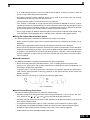
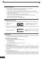
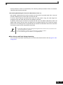
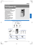
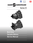
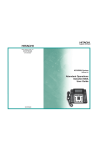
Spain Tel: +34 913 777 900 www.omron.es Belgium Tel: +32 (0) 2 466 24 80 www.omron.be Germany Tel: +49 (0) 2173 680 00 www.omron.de Norway Tel: +47 (0) 22 65 75 00 www.omron.no Sweden Tel: +46 (0) 8 632 35 00 www.omron.se Czech Republic Tel: +420 234 602 602 www.omron.cz Hungary Tel: +36 (0) 1 399 30 50 www.omron.hu Poland Tel: +48 (0) 22 645 78 60 www.omron.com.pl Switzerland Tel: +41 (0) 41 748 13 13 www.omron.ch Denmark Tel: +45 43 44 00 11 www.omron.dk Italy Tel: +39 02 32 681 www.omron.it Portugal Tel: +351 21 942 94 00 www.omron.pt Turkey Tel: +90 (0) 216 474 00 40 Pbx www.omron.com.tr Finland Tel: +358 (0) 207 464 200 www.omron.fi Middle East & Africa Tel: +31 (0) 23 568 11 00 www.omron-industrial.com Russia Tel: +7 095 745 26 64 www.omron.ru United Kingdom Tel: +44 (0) 870 752 08 61 www.omron.co.uk Quick START GUIDE Français Netherlands Tel: +31 (0) 23 568 11 00 www.omron.nl Italiano France Tel: +33 (0) 1 56 63 70 00 www.omron.fr VARISPEED F7 Austria Tel: +43 (0) 1 80 19 00 www.omron.at The Industrial Workhorse Model: CIMR-F7Z 200V Class 3-phase 0.4 to 110 kW 400V Class 3-phase 0.4 to 300 kW Español Manual No. I66E-EN-01 Omron Europe B.V. Wegalaan 67-69, NL-2132 JD, Hoofddorp, The Netherlands. Tel: +31 (0) 23 568 13 00 Fax: +31 (0) 23 568 13 88 www.omron-industrial.com VARISPEED F7 Deutsch English Manual No. I66E-EN-01 YASKAWA In the event that the end user of this product is to be the military and said product is to be employed in any weapons systems or the manufacture thereof, the export will fall under the relevand regulations as stipulated in the Foreign Exchange and Foreign Trade Regulations. Therefore, be sure to follow all procedures and submit all relevant documentation according to any and all rules, regulations and laws may apply. Specifications are subject to change without notice for ongoing product modifications and improvements. Quick Start Guide YASKAWA ELECTRIC CORPORATION Português Manufacturer © 2006 OMRON Yaskawa Motion Control. All rights reserved. Pyccкий Note: Specifications subject to change without notice. Manual No. I66E-EN-01 F7Z Quick Start Guide Table of Contents Warnings ...................................................................... EN-2 Safety Precautions and Instructions ........................................................................... EN-3 EMC Compatibility ...................................................................................................... EN-4 Installation .................................................................... EN-6 Mechanical Installation ............................................................................................... EN-6 Electrical Connection .................................................................................................. EN-8 Wiring Main Circuit Inputs ........................................................................................ EN-12 Keypad Operation ...................................................... EN-14 Digital Operator Display (optional) ............................................................................ EN-14 Power Up and Basic Parameter Setup ..................... EN-15 Start Up Procedure .................................................................................................. EN-15 Before Power Up ...................................................................................................... EN-16 Display after Power Up ............................................................................................. EN-16 Autotuning ................................................................................................................ EN-16 User Parameter .......................................................... EN-18 Troubleshooting ......................................................... EN-22 General Faults and Alarms ....................................................................................... EN-22 Operator Programming Errors .................................................................................. EN-24 Autotuning Faults ..................................................................................................... EN-24 Warnings CAUTION Cables must not be connected or disconnected, nor signal tests carried out, while the power is switched on. The Varispeed F7 DC bus capacitor remains charged even after the power has been switched off. To avoid an electric shock hazard, disconnect the frequency inverter from the mains before carrying out maintenance. Then wait for at least 5 minutes after all LEDs have gone out. Do not perform a withstand voltage test on any part of the Varispeed. The frequency inverter contains semiconductors, which are not designed for such high voltages. Do not remove the digital operator while the mains supply is switched on. The printed circuit board must also not be touched while the inverter is connected to the power. Never connect general LC/RC interference suppression filters, capacitors or overvoltage protection devices to the inverter input or output. To avoid unnecessary overcurrent faults, etc. being displayed, the signaling contacts of any contactor or switch fitted between inverter and motor must be integrated into the inverter control logic (e.g. baseblock). This is absolutely imperative! This manual must be read thoroughly before connecting and operating the inverter. All safety precautions and instructions for use must be followed. The inverter may must be operated with the appropriate line filters, following the installation instructions in this manual and with all covers closed and terminals covered. Only then will adequate protection be provided. Please do not connect or operate any equipment with visible damage or missing parts. The operating company is responsible for any injuries or equipment damage resulting from failure to heed the warnings in this manual. EN-2 Safety Precautions and Instructions General Please read these safety precautions and instructions for use thoroughly before installing and operating this inverter. Also read all of the warning signs on the inverter and ensure they are never damaged or removed. Live and hot inverter components may be accessible during operation. Removal of housing components, the digital operator or terminal covers runs the risk of serious injuries or damage in the event of incorrect installation or operation. The fact that frequency inverters control rotating mechanical machine components can give rise to other dangers. The instructions in this manual must be followed. Installation, operation and maintenance may only be carried out by qualified personnel. For the purposes of the safety precautions, qualified personnel are defined as individuals who are familiar with the installation, starting, operation and maintenance of frequency inverters and have the proper qualifications for this work. Safe operation of these units is only possible if they are used properly for their intended purpose. The DC bus capacitors can remain live for about 5 minutes after the inverter is disconnected from the power. It is therefore necessary to wait for this time before opening its covers. All of the main circuit terminals may still carry dangerous voltages. Children and other unauthorized persons must not be allowed access to these inverters. Keep these Safety Precautions and Instructions for Use readily accessible and supply them to all persons with any form of access to the inverters. Intended Use Frequency inverters are intended for installation in electrical systems or machinery. Their installation in machinery and systems must conform to the following product standards of the Low Voltage Directive: EN 50178, 1997-10, Equipping of Power Systems with Electronic Devices EN 60204-1, 1997-12Machine Safety and Equipping with Electrical Devices Part 1: General Requirements (IEC 60204-1:1997)/ Please note: Includes Corrigendum of September 1998 EN 61010-1, A2, 1995Safety Requirements for Information Technology Equipment (IEC 950, 1991 + A1, 1992 + A2, 1993 + A3, 1995 + A4, 1996, modified) CE marking is carried out to EN 50178, using the line filters specified in this manual and following the appropriate installation instructions. Transportation and storage The instructions for transportation, storage and proper handling must be followed in accordance with the technical data. Installation Install and cool the inverters as specified in the documentation. The cooling air must flow in the specified direction. The inverter may therefore only be operated in the specified position (e.g. upright). Maintain the specified clearances. Protect the inverters against impermissible loads. Components must not be bent nor insulation clearances changed. To avoid damage being caused by static electricity, do not touch any electronic components or contacts. EN-3 Electrical Connection Carry out any work on live equipment in compliance with the national safety and accident prevention regulations. Carry out electrical installation in compliance with the relevant regulations. In particular, follow the installation instructions ensuring electromagnetic compatibility (EMC), e.g. shielding, grounding, filter arrangement and laying of cables. This also applies to equipment with the CE mark. It is the responsibility of the manufacturer of the system or machine to ensure conformity with EMC limits. Your supplier or Omron Yaskawa Motion Control representative must be contacted when using leakage current circuit breaker in conjunction with frequency inverters. In certain systems it may be necessary to use additional monitoring and safety devices in compliance with the relevant safety and accident prevention regulations. The frequency inverter hardware must not be modified. Notes The Varispeed F7 frequency inverters are certified to CE, UL, and cUL EMC Compatibility Introduction This manual was compiled to help system manufacturers using OMRON YASKAWA Motion Control (OYMC) frequency inverters design and install electrical switch gear. It also describes the measures necessary to comply with the EMC Directive. The manual's installation and wiring instructions must therefore be followed. Our products are tested by authorized bodies using the standards listed below. Product standard: EN 61800-3:1996 EN 61800-3; A11:2000 Measures to Ensure Conformity of OYMC Frequency inverters to the EMC Directive OYMC frequency inverters do not necessarily have to be installed in a switch cabinet. It is not possible to give detailed instructions for all of the possible types of installation. This manual therefore has to be limited to general guidelines. All electrical equipment produces radio and line-borne interference at various frequencies. The cables pass this on to the environment like an aerial. Connecting an item of electrical equipment (e.g. drive) to a supply without a line filter can therefore allow HF or LF interference to get into the mains. The basic countermeasures are isolation of the wiring of control and power components, proper grounding and shielding of cables. A large contact area is necessary for low-impedance grounding of HF interference. The use of grounding straps instead of cables is therefore definitely advisable. Moreover, cable shields must be connected with purpose-made ground clips. EN-4 Laying Cables Measures Against Line-Borne Interference: Line filter and frequency inverter must be mounted on the same metal plate. Mount the two components as close to each other as possible, with cables kept as short as possible. Use a power cable with well-grounded shield. For motor cables up to 50 meters in length use shielded cables. Arrange all grounds so as to maximize the area of the end of the lead in contact with the ground terminal (e.g. metal plate). Shielded Cable: • Use a cable with braided shield. • Ground the maximum possible area of the shield. It is advisable to ground the shield by connect- ing the cable to the ground plate with metal clips (see following figure). Ground Clip Ground Plate Fig 1 Earthing the cable shield with metal clips The grounding surfaces must be highly conductive bare metal. Remove any coats of varnish and paint. – Ground the cable shields at both ends. – Ground the motor of the machine. EN-5 Installation Mechanical Installation Unpacking the Inverter Check the following items after unpacking the inverter. Item Has the correct Inverter model been delivered? Is the Inverter damaged in any way? Are any screws or other components loose? Method Check the model number on the nameplate on the side of the Inverter. Inspect the entire exterior of the Inverter to see if there are any scratches or other damage resulting from shipping. Use a screwdriver or other tools to check for tightness. If any irregularities in the above items are found, contact the agency from which the Inverter was purchased or your Omron Yaskawa Motion Control representative immediately. Checking the Installation Site Protection covers are attached to the top and bottom of the NEMA 1 / IP20 Inverters. Be sure to remove the top cover before operating a 200 or 400 V Class Inverter with a capacity of 18.5 kW or less inside a panel. Observe the following precautions when mounting the Inverter: • Install the Inverter in a clean location which is free from oil mist and dust. It can be installed in a totally enclosed panel that is completely shielded from floating dust. • When installing or operating the Inverter, always take special care so that metal powder, oil, water, or other foreign matter does enter the Inverter. • Do not install the Inverter on combustible material, such as wood. • Install the Inverter in a location free from radioactive materials and combustible materials. • Install the Inverter in a location free from harmful gasses and liquids. • Install the Inverter in a location without excessive oscillation. • Install the Inverter in a location free from chlorides. • Install the Inverter in a location without direct sunlight. EN-6 Installation Orientation Install the Inverter vertically so as not to reduce the cooling effect. When installing the Inverter, always provide the following installation space to allow normal heat dissipation. A B Air A B 200V class inverter, 0.55 to 90 kW 50 mm 120 mm 400V class inverter, 0.55 to 132 kW 200V class inverter, 110 kW 120 mm 120 mm 400V class inverter, 160 to 220 kW 400V class inverter, 300 kW 300 mm 300 mm 50mm min. 30mm min. 30mm min. 120mm min. Air Horizontal Space Vertical Space Fig 2 Installation space IMPORTANT 1. The same space is required horizontally and vertically for IP00, IP20 and NEMA 1 Inverters. 2. Always remove the top protection cover after installing an Inverter with an output of 18.5 kW or less in a panel. Always provide enough space for suspension eye bolts and the main circuit lines when installing an Inverter with an output of 22 kW or more in a panel. Installation of Inverters and EMC filters For an EMC rules compliant installation consider the following points: PE L2 L1 L3 Ground Bonds Remove any paint! • Use a line filter. • Use shielded motor cables. • Mount the inverter and filter on a PE grounded cunductive plate. • Remove any paint or dirt before mount- ing the parts in order to reach the lowest possible grounding impedance. Line Inverter Filter Load L2 V GND L1 L3 U W GND Cable Lenght as short as possible Grounded Metal Plate Screened Motor cable Ground Bonds Remove any paint! Fig 3 EMC filter installation M ~3 EN-7 Electrical Connection Wiring the Inverter DC reactor to improve input power factor (optional) Braking resistor unit (optional) Short-circuit bar Main Contactor 2 T B1 1 B2 Fuses 3-phase power L1 380 to 480 V L2 50/60 Hz Line Filter L3 R/L1 U/T1 S/L2 T/L3 W/T3 Varispeed F7 PE Multi-function digital inputs [Factory setting] M V/T2 Forward Run / Stop S1 Reverse Run / Stop S2 MB External Fault S3 MC Fault reset S4 Multi-step speed setting 1 S5 Multi-step speed setting 2 S6 Jog frequency selection S7 MA Fault relay output 250 VAC, 1 A max. 30 VDC, 1 A max. M1 M2 M3 M4 Relay output 1 [Default: Running] Relay output 2 [Default: Zero speed] SN M5 SC M6 SP Shield terminal 2CN RP Pulse train input [Default: Frequency reference input] 0 to 32 kHz Analog input setting adjustment PG Option Card +V Analog input power supply 15 V, 20 mA 2 kΩ Analog input 1: Master frequency reference 0 to 10 V (20 kΩ) 0 to 10 V A1 4 to 20 mA A2 Multi-function analog input 2 [Default: Frequency bias 4 to 20 mA (20 kΩ)] P Relay output 3 [Default: Frequency agree 1] 24 V E(G) 2 kΩ Multi-function digital output 250 VAC, 1 A max. 30 VDC, 1 A max. P AC 0V -V Analog input power supply -15 V, 20 mA Input Option Card Shield terminal E(G) 2CN MP AC FM Terminating resistance MEMOBUS communication RS-485/422 RAM S+ P AC SIG Shielded wires Fig 4 Wiring Diagram EN-8 Adjustment, 20 kΩ + FM Adjustment, 20 kΩ R+ P Pulse train output 0 to 32 kHz (2.20 kΩ) [Default: Output frequency] P Twisted-pair shielded wires + AM Multi-function analog output 1 (-10 to +10 V, 2 mA / 4 to 20 mA) [Default: Output frequency, 0 to 10 V) 4 to 20 mA (20 kΩ)] Multi-function analog output 2 (-10 to +10 V, 2 mA / 4 to 20 mA) [Default: Output current, 0 to 10 V) 4 to 20 mA (20 kΩ)] Main Circuit Terminals Main circuit terminal functions are summarized according to terminal symbols in Table 1. Wire the terminals correctly for the desired purposes. Table 1 Main Circuit Terminal Functions (200 V Class and 400 V Class) Purpose Model: CIMR-F7Z 200 V Class 400 V Class 20P4 to 2110 40P4 to 4300 2022 to 2110 4022 to 4300 20P4 to 2110 40P4 to 4300 Terminal Symbol R/L1, S/L2, T/L3 R1/L11, S1/L21, T1/L31 U/T1, V/T2, W/T3 Main circuit power input Inverter outputs DC bus terminals 1, Braking Resistor Unit Connection B1, B2 DC reactor connection 1, Braking Unit connection 3, 2 Ground 20P4 to 2110 40P4 to 4300 20P4 to 2018 40P4 to 4018 20P4 to 2018 40P4 to 4018 2022 to 2110 4022 to 4300 20P4 to 2110 40P4 to 4300 Control Circuit Terminals Fig 5 shows the control terminal arrangement. The functions of the control circuit terminals are shown in Table 2. Use the appropriate terminals for the correct purposes. Fig 5 Control terminal arrangement Table 2 Control Circuit Terminals with default settings Analog input signals Digital input signals Type No. Signal Name Function Signal Level S1 Forward run/stop command Forward run when ON; stopped when OFF. S2 Reverse run/stop command Reverse run when ON; stopped when OFF. S3 External fault input*1 Fault when ON. S4 Fault reset *1 Reset when ON 24 VDC, 8 mA Photocoupler isolation Functions are Auxiliary frequency ref*1 selected by seterence when ON. (Master/auxiliary switch) ting H1-01 to Multi-step speed reference 2 Multi-step speed 2 H1-05. *1 when ON. Multi-step speed reference 1 S5 S6 S7 Jog frequency reference *1 Jog frequency when ON. SC Digital input common – SN Digital Input Neutral – – – 24 VDC, 250 mA max. SP Digital Input Power Supply +24VDC power supply for digital inputs +V 15 V power output 15 V power supply for analog references 15 V (Max. curr.: 20mA) A1 Frequency reference 0 to +10 V/100% A2 Auxiliary Frequency Reference Auxiliary analog frequency reference; 4 to 20 mA (250Ω) -V -15 V power output -15 V power supply for analog references AC Analog reference common – – Shield wire, optional ground line connection point – – E(G) *2 -10 to +10 V (20 kΩ) 0 to +10 V (20 kΩ) Function is 4 to 20 mA (250 Ω) selected by set- 0 V to +10 V (20 kΩ) ting H3-09. 0 to 20 mA (250 Ω) EN-9 Type No. M1 Digital output signals M2 Signal Name Function During run (NO) Closed during Run Zero speed (NO) Closed when output frequency at zero level (b2-01) or below M3 M4 M5 M6 Speed agreement detection (NO) Signal Level Function selected by H2- Relay contacts 01 to H2-03 Contact capacity: 1 A max. at 250 VAC Within ± 2 Hz of set fre1 A max. at 30 VDC*3 quency when ON MA Fault output signal Closed across MA and MC during faults Open across MB and MC during faults FM Output frequency Analog output frequency signal; 0 to 10 V; 10V=FMAX AC Analog common – AM Inverter output power Analog output power signal; 0 to 10V; 10V=max. appl. motor capacity RP Pulse Input H6-01 (Frequency reference input) *4 0 to 32 kHz (3kΩ) High level voltage 3.5 to 13.2 V MP Pulse Output H6-06 (Output frequency) 0 to 32 kHz +15 V output (2.2kΩ) R+ S+ MEMOBUS communications input For 2-wire RS-485, short R+ and S+ MEMOBUS communications as well as R- and S-. S- output IG Signal common MB RS-485/422 Pulse I/O Analog output signals MC R- Function selected by H4-01 Function selected by H4-04 – 0 to +10 V max. ±5% 2 mA max. -10 to +10 V max. ±5% 2 mA max 4 to 20 mA Differential input, PHC isolation Differential input, PHC isolation – *1. The default settings are given for terminals S3 to S7. For a 3-wire sequence, the default settings are a 3-wire sequence for S5, multistep speed setting 1 for S6 and multi-step speed setting 2 for S7. *2. Do not use this power supply for supplying any external equipment. *3. When driving a reactive load, such as a relay coil with DC power supply, always insert a flywheel diode as shown in Fig 6 *4. Pulse input specifications are given in the following table: Low level voltage 0.0 to 0.8 V High level voltage 3.5 to 13.2 V H duty 30% to 70% Pulse frequency 0 to 32 kHz Flywheel diode External power: 30 VDC max. Coil 1 A max. The rating of the flywheel diode must be at least as high as the circuit voltage. Fig 6 Flywheel Diode Connection IMPORTANT EN-10 1. In Fig 4 the wiring of the digital inputs S1 to S7 is shown for the connection of contacts or NPN transistors (0V common and sinking mode). This is the default setting. For the connection of PNP transistors or for using a 24V external power supply, refer to Table 3. 2. A DC reactor is an option only for Inverters of 18.5 kW or less. Remove the short circuit bar when connecting a DC reactor. Sinking/Sourcing Mode (NPN/PNP Selection) The input terminal logic can be switched over between sinking mode (0-V common, NPN) and sourcing mode (+24V common, PNP) by using the jumper CN5. An external power supply is also supported, providing more freedom in signal input methods. Table 3 Sinking / Sourcing Mode and Input Signals Internal Power Source - Sinking Mode (NPN) External Power Source - Sinking Mode (NPN) External +24 V Internal Power Source - Sourcing Mode (PNP) External Power Source - Sourcing Mode (PNP) External +24 V EN-11 Wiring Main Circuit Inputs Installing Fuses To protect the inverter, it is recommended to use semiconductor fuses like they are shown in the table below. Table 4 Input Fuse Selection 20P4 20P7 21P5 22P2 23P7 25P5 27P5 2011 2015 2018 2022 2030 2037 2045 2055 2075 2090 2110 Rated Inverter Output Current (A) 3.2 4.1 7.0 9.6 15 23 31 45 58 71 85 115 145 180 215 283 346 415 40P4 40P7 41P5 42P2 43P7 44P0 45P5 47P5 4011 4015 4018 4022 4030 4037 4045 4055 4075 4090 4110 4132 1.8 2.1 3.7 5.3 7.6 8.7 12.5 17 24 31 39 45 60 75 91 112 150 180 216 260 480 480 480 480 480 480 480 480 480 480 480 480 480 480 480 480 480 480 480 480 5 5 10 10 15 20 25 30 50 60 70 80 100 125 150 150 250 300 350 400 4160 304 480 450 4185 370 480 600 4220 506 480 700 4300 675 480 900 Inverter Type Fuse Selection Selection Example (Ferraz) Voltage (V) Current (A) I2t (A2s) Model Rating I2t (A2s) 240 240 240 240 240 240 240 240 240 240 240 240 240 240 240 240 240 240 10 10 15 20 30 40 60 80 100 130 150 180 240 300 350 450 550 600 12~25 12~25 23~55 34~98 82~220 220~610 290~1300 450~5000 1200~7200 1800~7200 870~16200 1500~23000 2100~19000 2700~55000 4000~55000 7100~64000 11000~64000 13000~83000 A60Q12-2 A60Q12-2 A60Q15-2 A60Q20-2 A60Q30-2 A50P50-4 A50P80-4 A50P80-4 A50P125-4 A50P150-4 A50P150-4 A50P200-4 A50P250-4 A50P300-4 A50P350-4 A50P450-4 A50P600-4 A50P600-4 600V / 12A 600V / 12A 600V / 15A 600V / 20A 600V / 30A 500V / 50A 500V / 80A 500V / 80A 500V / 125A 500V / 150A 500V / 150A 500V / 200A 500V/ 250A 500V / 300A 500V / 350A 500V / 450A 500V / 600A 500V / 600A 17 17 26 41 132 250 640 640 1600 2200 2200 4000 6200 9000 12000 20000 36000 36000 6~55 6~55 10~55 18~55 34~72 50~570 100~570 100~640 150~1300 400~1800 700~4100 240~5800 500~5800 750~5800 920~13000 1500~13000 3000~55000 3800~55000 5400~23000 7900~64000 14000~25000 0 20000~25000 0 34000~40000 0 52000~92000 0 A60Q10-2 A60Q10-2 A60Q12-2 A60Q15-2 A60Q20-2 A60Q30-2 A60Q30-2 A60Q30-2 A70P50-4 A70P70-4 A70P80-4 A70P80-4 A70P100-4 A70P125-4 A70P150-4 A70P200-4 A70P250-4 A70P300-4 A70P350-4 A70P400-4 600V / 10A 600V / 10A 600V / 12A 600V / 15A 600V / 20A 600V / 30A 600V / 30A 600V / 30A 700V / 50A 700V / 70A 700V / 80A 700V / 80A 700V / 100A 700V / 125A 700V / 150A 700V / 200A 700V / 250A 700V / 300A 700V / 350A 700V / 400A 10 10 17 26 41 132 132 132 300 590 770 770 1200 1900 2700 4800 7500 11000 15000 19000 A70P450-4 700V / 450A 24000 A70P600-4 700V / 600A 43000 A70P700-4 700V / 700A 59000 A70P900-4 700V / 900A 97000 Consider the following precautions for the main circuit power supply input. • If a moulded case circuit breaker is used for the power supply connection (R/L1, S/L2, and T/L3), ensure that the circuit breaker is suitable for the Inverter. EN-12 • If an earth leakage breaker is used, it should be able to detect all kinds of current in order to ensure a safe earth leakage current detection • A magnetic contactor or other switching device can be used at the inverter input. The inverter should not be powered up more than once per hour. • The input phases (R/S/T) can be connected in any sequence. • If the Inverter is connected to a large-capacity power transformer (600 kW or more) or a phase advancing capacitor is switched nearby, an excessive peak current could flow through the input power circuit, causing an inverter damage. As a countermeasure install an optional AC Reactor at the inverter input or a DC reactor at the DC reactor connection terminals. • Use a surge absorber or diode for inductive loads near the Inverter. Inductive loads include mag- netic contactors, electromagnetic relays, solenoid valves, solenoids, and magnetic brakes. Wiring the Output Side of the Main Circuit The following precautions should be considered for the output circuit wiring. • Never connect any power source to the inverter output terminals. Otherwise the inverter can be damaged. • Never short or ground the output terminals. Otherwise the inverter can be damaged. • Do not use phase correction capacitors. Otherwise the inverter and capacitors can be damaged. • Check the control sequence to make sure, that the magnetic contactor (MC) between the Inverter and motor is not turned ON or OFF during inverter operation. If the MC is turned ON during the Inverter is operation, a large inrush current will be created and the inverter’s overcurrent protection may operate. Ground Connection The following precautions should be considered for the ground connection. • Do not share the ground wire with other devices, such as welding machines or power tools. • Always use a ground wire, that complies with technical standards on electrical equipment and minimize the length of the ground wire. Leakage current is caused by the Inverter. Therefore, if the distance between the ground electrode and the ground terminal is too long, potential on the ground terminal of the Inverter will become unstable. • When more than one Inverter is used, do not to loop the ground wire. NO OK Fig 7 Ground Wiring Control Circuit Wiring Precautions Consider the following precautions for wiring the control circuits. • Separate control circuit wiring from main circuit wiring (terminals R/L1, S/L2, T/L3, B1, B2, U/T1, V/T2, W/T3, B1, B2, , 1, 2, and 3, PO, NO) and other high-power lines. • Separate wiring for control circuit terminals MA, MB, MC, M1 to M6 (relay outputs) from wiring to other control circuit terminals. • If an optional external power supply is used, it should be a UL Listed Class 2 power supply. • Use twisted-pair or shielded twisted-pair cables for control circuits to prevent operating faults. • Ground the cable shields with the maximum contact area of the shield and ground. • Cable shields have to be grounded on both cable ends. EN-13 Keypad Operation Digital Operator Display (optional) The key names and functions of the Digital Operator are described below Drive Mode Indicators FWD: Lights up when a forward run command is input. REV: Lights up when a reverse run command is input. SEQ: Lights up when any other run command source than the Digital Operator is selected. REF: Lights up when any other frequency reference source than the Digital Operator is selected. ALARM: Lights up when an error or alarm has occurred. Data Display Displays monitor data, parameter numbers, and settings. Mode Display (displayed at the upper left of the data display DRIVE: Lights up in Drive Mode. QUICK: Lights up in Quick Programming Mode. ADV: Lights up in Advanced Programming Mode. VERIFY:Lights up in Verify Mode. A. TUNE:Lights up in Autotuning Mode. Keys Execute operations such as setting user parameters, monitoring, jogging, and autotuning. Digital Operator Keys Key Name LOCAL/REMOTE Key MENU Key Selects the modes. ESC Key Returns to the status before the DATA/ENTER Key was pressed. JOG Key Enables jog operation when the Inverter is being operated from the Digital Operator. FWD/REV Key Selects the rotation direction of the motor when the Inverter is being operated from the Digital Operator. Shift/RESET Key Sets the active digit when programming user parameters. Also acts as the Reset key when a fault has occurred. Increment Key Decrement Key EN-14 Function Switches between operation via the Digital Operator (LOCAL) and the settings in b1-01 and b1-02 (REMOTE). This key can be enabled or disabled by setting parameter o2-01. Selects user parameter numbers and increments parameter settings. Used to move to the next item or data. Selects user parameter numbers and decrements parameter settings. Used to move to the previous item or data. DATA/ENTER Key Enters menus and parameters and validates parameter settings. RUN Key Starts operation when the Inverter is being controlled by the Digital Operator (LOCAL Mode). STOP Key Stops Inverter operation (LOCAL and REMOTE Mode). This key can be enabled or disabled when operating from a source different tan the operator by setting parameter o2-02. Power Up and Basic Parameter Setup Start Up Procedure START Installation Wiring Set power supply voltage jumper *1 Turn ON power Confirm status Select control method. Basic settings (Quick programming mode) NO V/f control Vector Control (A1-02 = 2 or 3) *5 YES YES PG? V/f Control with PG (A1-02 = 1 NO V/f control Set E1-03. V/f default: 200V/50Hz (400V/50Hz) Set E1-03, E2-04 and F1-01. *2 V/f default: 200V/50Hz (400V/50Hz) Settings according to control mode Motor operation possible during autotuning? *3 NO YES Non-rotating autotuning for line-to-line resistance Application settings (Advanced programming mode) No-load operation Loaded operation Optimum adjustments and parameter settings Check/record parameter settings END *4 Rotating autotuning *6 Non-rotating *6 autotuning 1. Set for 400 V Class Inverter for 75 kW or more. 2. If there is a reduction gear between the motor and PG, set the reduction ratio in F1-12 and F1-13 in advanced programming mode. 3. Use rotational autotuning to increase autotuning accuracy whenever it is okay for the motor to be operated. 4. If the motor cable changes to 50 m or longer for the actual installation, perform non-rotating autotuning for the line-to-line resistance only on site. 5. The default control mode is Open Loop Vector control (A1-02=2). 6. If the maximum output frequency and the base frequency are different, set the maximum output frequency (E1-04) after autotuning. Fig 8 Trial Operation Flowchart EN-15 Before Power Up The following points should be checked carefully before the power is switched on. • Check if the power supply meets the inverter specification. • Check if the power supply cables are tightly connected to the right terminals (L1, L2, L3). • Check if the motor cables are tightly connected to the right terminals on the inverter side (U, V, W) as well as on the motor side. • Check if the braking unit / braking resistor is connected correctly. • Check if the Inverter control circuit terminal and the control device are wired correctly. • Set all Inverter control circuit terminals to OFF. • When a PG card is used, check if it is wired correctly. Display after Power Up After normal power up without any problems the operator display shows the following messages Display for normal operation Rdy -DRIVE- Frequency Ref U1- 01=50.00Hz U1-02=50.00Hz U1-03=10.05A The frequency reference monitor is displayed in the data display section. When a fault has occurred or an alarm is active a fault or alarm message will appear. In this case, refer to page 21, Troubleshooting. -DRIVE- Display for fault operation UV DC Bus Undervolt A fault or alarm message is shown on the display. The example shows a low voltage alarm. Autotuning Autotuning sets motor parameters automatically when using Open Loop or Closed Loop Vector control, when the cable length is long or the installation has changed. Setting the Autotuning Mode One of the following three autotuning modes can be set. • Rotating autotuning • Non-rotating autotuning • Non-rotating autotuning for line-to-line resistance only Rotating Autotuning (T1-01 = 0) Rotating autotuning is used for Open Loop and Closed Loop Vector control only. Set T1-01 to 0, input the data from the motor nameplate, and then press the RUN key on the Digital Operator. The Inverter will operate the motor for approximately 1 minute and set the required motor parameters automatically. Non-rotating Autotuning (T1-01 = 1) Non-rotating autotuning is used for Open Loop and Closed Loop Vector control only. Set T1-01 to 1, input the data from the motor nameplate, and then press the RUN key on the Digital Operator. The inverter will supply power to the non-rotating motor for approximately 1 minute and some of the EN-16 motor parameters will be set automatically. The remaining motor parameters will be set automatically during the first time operation. Non-rotating Autotuning for Line-to-Line Resistance (T1-01 = 2) Non-rotating autotuning for line-to-line resistance can be used in any control mode. This is the only possible autotuning for V/f control and V/f control with PG. It can be used to improve the performance when the motor cable is long, the cable length has changed or when the motor and inverter have different capacities. To perform autotuning in V/f control or V/f control with PG, set T1-02 (Motor rated power) and T1-04 (Motor rated current) and then press the RUN key on the Digital Operator. The Inverter will supply power to the non-rotating motor for approximately 20 seconds and the Motor line-to-line resistance and cable resistance will be automatically measured. IMPORTANT 1. Power will be supplied to the motor during autotuning but the motor will not turn. Do not touch the motor until autotuning has been completed. 2. Ensure that all motor contactors are closed before the autotuning is started. 3. To cancel autotuning press the STOP key on the Digital Operator. Other Alarms and Faults During Autotuning For an overview of possible autotuning alarms or faults and corrective actions refer to page 24, Autotuning Faults. EN-17 User Parameter Parameter Number Name Description A1-01 A1-02 A1-03 Language selection for Digital Operator display(JVOP160-OY only) 0:English 2: German 3: French 4: Italian 5: Spanish 6: Portuguese Parameter access level 0:Monitoring only (Monitoring drive mode and setting A1-01 and A1-04.) 1: Used to select user parameters (Only parameters set in A2-01 to A2-32 can be read and set.) 2: Advanced (Parameters can be read and set in both, quick programming mode (Q) and advanced programming mode (A). 0:V/f control Control method 1: V/f control with PG 2: Open loop vector control selection 3: Closed loop vector control Initialize 0: No initializing 1110:Initializes using the user parameters 2220:Initializes using a two-wire sequence. (Initializes to the factory setting.) 3330: Initializes using a three-wire sequence. Sequence / Reference Source Reference source selection Sets the frequency reference input method. 0:Digital Operator 1: Control circuit terminal (analog input) 2: Serial communication (RS422 / 485) 3: Option Card RUN command source selection Sets the run command input method. 0:Digital Operator 1: Control circuit terminal (digital inputs) 2: Serial communication (RS422 / 485) 3: Option Card b1-03 Stopping method selection Selects the stopping method when the Run signal is removed 0:Deceleration to stop 1: Coast to stop 2: DC injection to stop 3: Coast to stop with timer (New Run commands are disregarded while coasting.) b1-04 Prohibition of reverse operation 0:Reverse enabled 1: Reverse disabled 2: Output Phase Rotation (both rotational directions are enabled) 3: Output Phase Rotation with Reverse disabled. b1-01 b1-02 Acceleration / Deceleration Settings C1- Acceleration/ Deceleration times C2- Description Sets the time to accelerate/decelerate from 0 Hz to the maximum output frequency. C3-01 Used to improve speed accuracy Slip compensa- • Increase if output frequency is too low tion gain • Decrease if output frequency is too high. C3-02 Sets the slip compensation delay time Slip compensa• Increase if output frequency is not tion delay time stable (only available • Decrease setting when slip compenin V/f and OLV) sation responsiveness is low. Speed Control (ASR) (only available in V/f with PG and CLV) C5-01 ASR proportional gain 1 Sets the proportional gain of the speed loop (ASR) C5-02 ASR integral time 1 Sets the integral time of the speed loop (ASR) C5-03 ASR proportional gain 2 C5-04 ASR integral time 2 C5-06 ASR delay time Sets the ASR filter time constant. (only CLV) C5-07 ASR switching frequency (only CLV) Sets the frequency for switching between ASR gain 1, 2 and ASR integral time 1, 2 C5-08 ASR integral limit (only CLV) Sets the limit for the integral part of the ASR controller. Sets the S-curve characteristic at acceleration start and end. P,I P = C5-01 I = C5-02 P = C5-03 I = C5-04 0 E1-04 Motor speed (Hz) Carrier Frequency C6-01 C6-02 Heavy/Normal duty selection 0:Heavy Duty 1: Normal Duty 1 2: Normal Duty 2 Carrier frequency selection Selects the carrier frequency (factory setting depends on Inverter capacity) 0: Low noise, low carrier 1: 2.0 kHz 2: 5.0 kHz 3: 8.0 kHz 4: 10.0 kHz 5: 12.5 kHz 6: 15.0 kHz F: Programmable pattern Speed Settings d1-01 to d1-16 Multi speed references 1 to 16 d1-17 Jog frequency reference Sets the multi-step speed references. Torque Control (only available in CLV) d5-01 Torque control selection 0:Speed control 1: Torque control d5-06 Speed/torque control switch over timer Sets the delay from inputting a “speed/ torque control change” signal (by digital input) until the control is acutally changed S-Curve Settings S-curve characteristic time at acceleration Name Motor Slip Compensation (not available in V/f with PG) Initialize Data A1-00 Parameter Number V/f Pattern Settings E1-01 EN-18 Input voltage setting This setting is used as a reference value for protection functions. Parameter Number Name Max. output E1-04 frequency (FMAX) Description H3-13 Frequency (Hz) E1-13 Base Voltage (VBASE) To set V/f characteristics in a straight line, set the same values for E1-07 and E1-09. In this case, the setting for E1-08 will be disregarded. Always ensure that the four frequencies are set in the following order: E1-04 (FMAX) ≥ E1-06 (FA) > E1-07 (FB) ≥ E1-09 (FMIN) Motor rated current E2-02 Motor rated slip E2-03 Motor no-load current E2-04 Number of motor poles Pulse Train I/O Pulse train H6-01 input function selection H6-07 Sets the motor data. Motor rated output power PG Option Setup F1-01 PG constant Sets the number of PG pulses per revolution F1-05 PG rotation 0:Phase A leads with forward run command 1:Phase B leads with forward run command Pulse train input scaling Pulse monitor scaling H1-01 Terminal S3 to Refer to page 20, Digital Input Function Selections (H1-01 to H1-05) for a S7 function to H1-05 selection list of selections Sets the number of pulses in Hz that is equivalent to 100% of the input item selected in H6-01. Stall prevention selection L3-01 during accel (not available in CLV) Stall prevenL3-04 tion selection during decel 0:Disabled (Deceleration as set. If deceleration time is too short, a DC bus overvoltage may result.) 1:Enabled (Deceleration is stopped when the DC bus voltage exceeds the stall prevention level. Deceleration restarts when the voltage falls below the stall prevention level again.) 2:Intelligent deceleration mode (Deceleration rate is automatically adjusted so that the Inverter can decelerate in the shortest possible time. The set deceleration time is disregarded.) 3:Enabled with braking resistor Refer to page 20, Digital Output Function Selections for a list of selections Selects the signal level input at multifunction analog input A2. Analog input 0:0 to +10 V (11 bit). H3-08 A2 signal level 1:-10 to +10 V 2:4 to 20 mA (9-bit input). selection Ensure to switch S1-2 to “V” before using a voltage input. Selects the multi-function analog input function for terminal A2. Sets the number of pulses output in Hz when the monitor item is 100%. 0:Disabled (Acceleration as set. With a heavy load, the motor may stall.) 1:Enabled (Acceleration stopped when L3-02 level is exceeded. Acceleration starts again when the current has fallen below the stall prevention level). 2:Intelligent acceleration mode (Using the L3-02 level as a basis, acceleration is automatically adjusted. Set acceleration time is disregarded.) Analog I/O Settings Analog input H3-09 A2 function selection. Selects the pulse train input function 0:Frequency reference 1:PID feedback value 2:PID target value Stall Prevention Digital I/O Settings Terminal M1H2-01 M2 and M3and H2-02 M4 function selection Selects on which terminal the main frequency reference can be input. 0:Use analog input 1 on terminal A1 for main frequency reference. 1:Use analog input 2 on terminal A2 for main frequency reference. Pulse train Selects the pulse train monitor output H6-06 monitor selecitem (U1-) tion Motor E2-09 mechanical losses E2-11 Terminal A1/ A2 switching Description Terminal FM H4-01 monitor selecSets the number of the monitor item tion to be output (U1-) at terminal FM/ Terminal AM AM. H4-04 monitor selection H6-02 Motor Data Settings E2-01 Name Output Voltage (V) Max. output E1-05 voltage (VMAX) Base freE1-06 quency (FA) Parameter Number Fault Restart Number of L5-01 auto restart attempts Sets the number of auto restart attempts. Automatically restarts after a fault and conducts a speed search from the run frequency. Auto restart L5-02 operation selection Sets whether a fault relay is activated during fault restart. 0:No output (Fault relay is not activated.) 1:Output (Fault relay is activated.) EN-19 Parameter Number Name Parameter Number Description Forward drive torque limit Reverse drive L7-02 torque limit Sets the torque limit vlaue as a percentage of the motor rated torque. Four individual regions can be set. Output torque Positive torque Forward L7-03 regenerative torque limit Reverse No. o motor rotations Regen. Regen. Reverse L7-04 regenerativ torque limit Forward U2-01 Current fault U2-02 Last fault U2-03 Reference frequency at fault U2-04 Output frequency at fault U2-05 Output current at fault U2-07 Output voltage reference at fault U2-08 DC bus voltage at fault U2-09 Output power at fault Negative torque U2-11 Input terminal status at fault U2-12 Output terminal status at fault Monitor Data U2-13 Operation status at fault U1-01 Frequency reference in Hz / rpm U2-14 Cumulative operation time at fault U1-02 Output frequency in Hz / rpm Fault History Data U1-03 Output current in A U3-01 to Last fault to fourth last fault U3-04 U1-06 Output voltage in VAC U1-07 DC bus voltage in VDC U1-08 Output power in kW U1-09 Torque reference Shows input ON/OFF status. U1-10 = U1-10 1: FWD command (S1) is ON 1: REV command (S2) is ON 1: Multi input 1 (S3) is ON 1: Multi input 2 (S4) is ON 1: Multi input 3 (S5) is ON 1: Multi input 4 (S6) is ON 1: Multi input 5 (S7) is O N Input terminal status U3-05 to Cumulative operation time at fault 1 to 4 U3-08 U3-09 to Fifth last to tenth last fault U3-14 U3-15 to Accumulated time of fifth to tenth fault U3-20 * The following faults are not recorded in the error log: CPF00, 01, 02, 03, UV1, and UV2. Digital Input Function Selections (H1-01 to H1-05) 3 Multi-step speed reference 1 4 Multi-step speed reference 2 Shows output ON/OFF status. 5 Mulit-step speed reference 3 U1-11 = 6 Jog frequency command (higher priority than multistep speed reference) 7 Accel/decel time selection 1 1: Multi-function contact output 1 (M1-M2) is ON 1: Multi-function contact output 2 (M3-M4) is ON 1: Multi-function contact output 3 (M5-M6) is ON Not used (Always 0). 1: Error output (MA/MB-MC) is ON Output termiU1-11 nal status Inverter operating status. U1-12 = F Not used (Set when a terminal is not used) 14 Fault reset (Reset when turned ON) 19 20 to 2F 1: Zero speed Operation status 1: Reverse Speed/torque control change (ON: Torque control) 77 Speed control (ASR) gain switching (ON: C5-03) Digital Output Function Selections (H2-01 and H2-02 0 During run 1 (ON: run command is ON or voltage is being output) 6 Inverter operation ready; READY: After initialization or no faults F Not used. (Set when the terminal is not used.) 10 Minor fault (Alarm) (ON: Alarm displayed) 1: Reset signal input 1: Speed agree 1: Inverter ready 1A During reverse run (ON: During reverse run) 1F Motor overload (OL1, including OH3) pre-alarm (ON: 90% or more of the detection level) 30 During torque limit (current limit) (ON: During torque limit) 32 Activated if the ASR is operating for torque limit. The ASR output becomes the torque reference, the motor is rotating at the speed limit. 1: Minor fault 1: Major fault U1-13 Cumulative operation time in hrs. U1-21 ASR input U1-22 ASR output U1-34 OPE fault parameter U1-40 Cooling fan operating time in hrs. EN-20 PI control disable External fault; Input mode: NO contact/NC contact, Detection mode: Normal/during operation 71 Run U1-12 Description Fault Trace Data Torque Limit (only OLV and CLV) L7-01 Name Troubleshooting General Faults and Alarms Faults and Alarms indicate unsusal inverter / application conditions. An alarm does not necessarily switch off the inverter but a message is displayed on the keypad (i.e. a flashing alarm code) and an alarm output can be generated at the multi-function outputs (H2-01 and H2-02) if programmed. An alarm automatically disappears if the alarm condition is not present anymore. A fault switches the inverter output off immediately, a message is displayed on the keypad and the fault output is switched. The fault must be reset manually after the cause and the RUN signal have been removed. The following table shows a list of faults and alarms with their corrective actions. Display Alarm BUS Option Com Err Fault Meaning Corrective Actions Option Card Communication Alarm Check the connections and all user-side softAfter initial communication was established, the ware configurations. connection was lost. Control Fault A torque limit was reached continuously for 3 Check the motor parameters seconds or longer during a deceleration stop in Open Loop Vector control Digital Operator Communication Fault 1/2 • Communication fault between Operator and Inverter • CPU External RAM Fault CPF02 BB Circuit Err CPF02 Fault Baseblock circuit error CPF03 EEPROM Error CPF03 EEPROM error CPF04 INternal A/D Err CPF04 CPU Internal A/D Converter Fault CF Out of Control CPF00 COMERR(OP&INV) CPF01 COMERR(OP&INV) DEV Speed Deviation EF External Fault EFx Ext Fault Sx Ext Run Active Cannot Reset GF Ground Fault • Perform an initialization to factory defaults. • Cycle the Inverter power supply. • Replace the Inverter. F1-04 = 0, 1 or 2 and A1-02 = 1 or 3 • Reduce the load. The speed deviation has been greater than the • Lengthen the acceleration and deceleration setting in F1-10 for a time longer than the setting time F1-11. • Check the mechanical system • Check the settings of F1-10 and F1-11 F1-04 = 3 and A1-02 = 1 or 3 The speed deviation has been greater than the • Check the sequence and if the brake is opened when the inverter starts to increase setting in F1-10 for a time longer than the setting the speed. F1-11. Forward/Reverse Run Commands Input Together Check external sequence logic, so that only Both the forward and the reverse run commands one input is activated at a time. are input simultaneously for 500ms or more. This alarm stops the motor. EF0 Opt External Flt • Disconnect the Digital Operator and then connect it again. • Cycle the Inverter power supply. • Replace the Inverter. • Check for an external fault condition. • Verify the parameters. • Verify communication signals External fault input from Communications Option Card External fault at terminal Sx (x stands for termi- Eliminate the cause of the external fault connals S3 to S7) dition. Detected after a fault when a RESET command Remove the RUN signal first and reset the is input while the RUN command is still active error. • Remove the motor and run the Inverter without the motor. • Check the motor for a phase to ground Ground Fault short. The ground current at the Inverter output exceeded 50% of the Inverter rated output cur- • Check the output current with a clampmeter to verify the DCCT reading. rent and L8-09=1 (Enabled). • Check the control sequence for wrong motor contactor signals. EN-21 Display Alarm OC Over Current Fault OH Heatsnk Overtemp OH1 Heatsink Max Temp Meaning Corrective Actions • Remove the motor and run the Inverter without the motor. • Check the motor for a phase-to-phase Over Current The Inverter’s output current exceeded the over- short. • Verify the accel/decel times (C1-). current detection level. • Check the Inverter for a phase-to-phase short at the output. Heatsink Overheat • Check for dirt build-up on the fans or heatL8-03 = 0,1 or 2 and the temperature of the sink. Inverter's cooling fin exceeded the L8-02 value. • Reduce the ambient temperature around Inverter's Cooling Fan Stopped the drive. L8-03 = 3 or 4 and the temperature of the • Replace the cooling fan(s). Inverter's cooling fin exceeded the L8-02 value. Heatsink Overheat The temperature of the Inverter’s heatsink exceeded 105 °C. Inverter’s Cooling Fan Stopped OL1 Motor Overload OL2 Inv Overload Motor Overload Detected when L1-01 is set to 1,2 or 3 and the • Recheck the cycle time and the size of the Inverter’s I²t value exceeded the motor overload load as well as the accel/decel times (C1curve. ). The overload curve is adjustable using parame• Check the V/f characteristics (E1-). ter • Check the setting of Motor Rated Current E2-01 (Motor Rated Current), L1-01 (Motor ProSetting (E2-01). tection Selection) and L2-02 (Motor Protection Time Constant) • Recheck the cycle time and the size of the load as well as the accel/decel times (C1Inverter Overload ). The Inverter output current exceeded the Invert• Check the V/f Characteristics (E1-). ers’s overload capability • Check if the inverter rated current matches the motor rated current. F1-03 = 0, 1 or 2 and A1-02 = 1 or 3 The motor speed feedback (U1-05) exceeded the setting in F1-08 for a time longer than the setting of F1-09 OS Overspeed Det. F1-03 = 3 and A1-02 = 1 or 3 The motor speed feedback (U1-05) exceeded the setting in F1-08 for a time longer than the setting of F1-09 (only in stop conditio) PF Input Phase Loss Input Phase Loss Too big DC bus voltage ripple. Only detected when L8-05=1 (enabled) PGO PG Open EN-22 • Adjust the ASR settings in the C5 parameter groupt • Check the reference circuit and reference gain. • Check the settings in F1-08 and F1-09 • Increase the deceleration time (C1-02/04) The DC bus voltage has exceeded the overvoltor connect a braking option. age detection level. • Check the power supply and decrease the Default detection levels are: voltage to meet the inverter’s specifica200 V class: 410 VDC tions. 400 V class: 820 VDC • Check the braking chopper / resistor. OV DC Bus Overvolt • Check for dirt build-up on the fans or heatsink. • Reduce the ambient temperature around the drive. • Replace the cooling fan(s). • Tighten the input terminal screws • Check the power supply voltage PG Disconnection Detected when F1-02 = 0, 1 or 2 and A1-02 = 1 or 3. • Fix the broken/disconnected wiring. Detected when no PG (encoder) pulses have • Supply power to the PG properly. been received for a time longer than the setting • Check the sequence and if the brake is in F1-14. opened when the inverter starts to increase PG Disconnection the speed. Detected when F1-02 = 3 and A1-02 = 1 or 3. PG (encoder) pulses have not been received for a time longer than the setting in F1-14. Alarm Display Fault PUF DC Bus Fuse Open RR DynBrk Transistr (only in UV1 stop DC Bus Undervolt conditio) UV2 CTL PS Undervolt Meaning Corrective Actions • Check the motor and the motor cables for DC Bus Fuse Open short circuits or insulation failures (phaseThe fuse in the main circuit is blown. to-phase). Warning: PG (encoder) pulses have not been received for • Replace the inverter after correcting the fault. a time longer than the setting in F1-14. Dynamic Braking Transistor The built-in dynamic braking transistor failed • Cycle power to the inverter. • Replace the inverter. The DC bus voltage is below the Undervoltage Detection Level (L2-05). The default settings are: 200V class: 190 VDC 400 V class: 380 VDC • Check the input voltage. • Check the wiring of the input terminals. • Check the input voltage and the wiring of the input terminals. • Extend the settings in C1-01/03 Main Circuit MC Operation Failure No MC response during Inverter operation. Replace the Inverter. Control Power Supply Undervoltage Undervoltage of the control circuit while the Inverter was running. • Remove all connection to the control terminals and cycle the power to the Inverter. • Replace the Inverter. Operator Programming Errors An Operator Programming Error (OPE) occurs when two or more parameter related to each other are set inappropriately or an individual parameter setting is incorrect. The Inverter does not operate until the parameter setting is corrected; however, no other alarm or fault output will occur. If an OPE occurs, change the related parameter by checking the cause shown in the table below. When an OPE error is displayed, press the ENTER key to see U1-34 (OPE Detected). This monitor displays the parameter that is causing the OPE error. Display OPE01 kVA Selection Meaning Corrective Actions Inverter kVA Setting Error Enter the correct kVA setting in o2-04. OPE02 Limit Parameter setting is out of its range Verify the parameter settings. OPE03 Terminal One of the following errors has been made in the multifunction input (H1-01 to H1-05) settings: • Duplicate functions were selected. • UP/DOWN Command(10 and 11) were not selected simultaneously. • The up/down commands (10 and 11) and Accel/ Decel Ramp Hold (A) were selected at the same time. • More than one of the Speed Search inputs (61, 62, 64) were set simultaneously. Verify the parameter settings in H1- • External Baseblock NO (8) and External Baseblock NC (9) were selected at the same time. • The up/down commands (10 and 11) were selected while PID Control was enabled. • The Emergency Stop Command NO (15) and NC(17) are set simultaneously. • PID is enabled and UP and/or DOWN (10 / 11) command are set. • HSB (68) and KEB (65/66) command are set simultaneously. RUN/Reference Command Selection Error • Verify that the board is installed. Remove the power The Reference Source Selection b1-01 and/or the RUN OPE05 supply and re-install the option board again Sequence Select Source Selection parameter b1-02 are set to 3 (option • Recheck the setting of b1-01 and b1-02 board) but no option board is installed. OPE06 PG Opt Missing Control Method Selection Error Verify the control method selection in parameter A1-02 One of the control methods needing a PG feedback was selected (A1-02 = 1 or 3), but a PG option board is and/or the installation of the PG option board. not installed. EN-23 Display Meaning Corrective Actions Function Selection Error A setting has been made that is applicable with the curOPE08 Verify the control method and the function. rent control method. Constant Selection Example: A function used only with open loop vector control was selected for V/f control. OPE010 V/f Ptrn Setting Check parameters (E1-). A frequency/voltage value may be set higher than the maximum frequency/voltage. V/f Parameter Setting Error Autotuning Faults Autotuning faults are shown below. When the following faults are detected, the fault is displayed on the digital operator and the motor coasts to stop. No fault or alarm outputs will be operated. Display Er-01 Fault Meaning Motor data fault Er-02 Minor Fault Alarm • Check the input data. • Check wiring and the machine. • Check the load. Er-03 STOP key STOP key input - Er-04 Resistance Line-to-Line Resistance Fault Autotuning result is outside the parameter setting range. No-Load Current Fault Er-05 Autotuning result is outside the parameter setting No-Load Current range. Er-08 Rated slip Rated Slip Fault Autotuning result is outside the parameter setting range. Er-09 Accelerate Acceleration Fault (Rotating autotuning only) The motor did not accelerate in the specified time (C1-10+10sec.) • • • • Check the input data. Check the motor wiring. If the motor is connected to the machine, disconnect it. If the setting of T1-03 is higher than the Inverter input power supply voltage (E1-01), change the input data. • Increase C1-01(Acceleration time) • Increase L7-01 and L7-02 (Torque limits) • If the motor is connected to the machine, disconnect it. Er-11 Motor Speed • If the motor is connected to the machine, disconnect it. Motor Speed Fault (Rotating autotuning only) The torque reference exceeded 100% during accel- • Increase C1-01 eration. Deteceted only when A1-02 = 2 or 3 (Vector • Check the input data (particularly the number of PG pulses and the number of motor poles) control modes). Er-12 I-det. Circuit Current Detection Fault • The current exceeded the motor rated current. • Any of U/T1, V/T2 and W/T3 has open-phase. Check wiring of the Inverter and the mounting. Er-13 Leakage Inductance Fault Leakage Inductance Fault Autotuning result is outside the parameter setting range. Check motor wiring. End-1 V/f Over Setting Rated Current Setting Alarm Displayed after auto-tuning is complete Check the motor rated current value. During auto-tuning, the measured value of motor rated current (E2-01) was higher than the set value. End-2 Saturation End-3 Rated FLA Alm EN-24 Corrective Actions • Check the input data. • Check the Inverter and motor capacity. • Check the motor rated current and no-load current setting. Motor Core Saturation Alarm (only for rotating autotuning) • Check the input data • Check the motor wiring. • If the motor is connected to the machine, disconnect it. Rated Current Setting Alarm During autotuning the measured value of motor rated Check the motor rated current value current (E2-01) was greater than the set value.