1
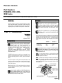
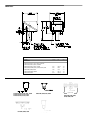
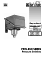
IMPSW850
User’s Guide
Shop on line at
www.omega.com
e-mail: [email protected]
PSW-850 SERIES
Pressure Switches
OMEGAnet ® On-Line Service
www.omega.com
Internet e-mail
[email protected]
Servicing North America:
USA:
ISO 9001 Certified
Canada:
One Omega Drive, P.O. Box 4047
Stamford CT 06907-0047
TEL: (203) 359-1660
e-mail: [email protected]
976 Bergar
Laval (Quebec) H7L 5A1
TEL: (514) 856-6928
e-mail: [email protected]
FAX: (203) 359-7700
FAX: (514) 856-6886
For immediate technical or application assistance:
USA and Canada: Sales Service: 1-800-826-6342 / 1-800-TC-OMEGA®
Customer Service: 1-800-622-2378 / 1-800-622-BEST®
Engineering Service: 1-800-872-9436 / 1-800-USA-WHEN®
TELEX: 996404 EASYLINK: 62968934 CABLE: OMEGA
Mexico:
En Espan˜ol: (001) 203-359-7803
FAX: (001) 203-359-7807
e-mail: [email protected]
[email protected]
Servicing Europe:
Benelux:
Postbus 8034, 1180 LA Amstelveen, The Netherlands
TEL: +31 (0)20 6418405
FAX: +31 (0)20 6434643
Toll Free in Benelux: 0800 0993344
e-mail: [email protected]
Czech Republic:
Rudé armády 1868, 733 01 Karviná 8
TEL: +420 (0)69 6311899
Toll Free: 0800-1-66342
France:
9, rue Denis Papin, 78190 Trappes
TEL: +33 (0)130 621 400
Toll Free in France: 0800-4-06342
e-mail: [email protected]
FAX: +420 (0)69 6311114
e-mail: [email protected]
FAX: +33 (0)130 699 120
Germany/Austria: Daimlerstrasse 26, D-75392 Deckenpfronn, Germany
TEL: +49 (0)7059 9398-0
Toll Free in Germany: 0800 639 7678
e-mail: [email protected]
United Kingdom:
ISO 9002 Certified
FAX: +49 (0)7056 9398-29
One Omega Drive, River Bend Technology Centre
Northbank, Irlam, Manchester
M44 5EX United Kingdom
TEL: +44 (0)161 777 6611
FAX: +44 (0)161 777 6622
Toll Free in United Kingdom: 0800-488-488
e-mail: [email protected]
It is the policy of OMEGA to comply with all worldwide safety and EMC/EMI regulations that
apply. OMEGA is constantly pursuing certification of its products to the European New Approach
Directives. OMEGA will add the CE mark to every appropriate device upon certification.
The information contained in this document is believed to be correct, but OMEGA Engineering, Inc. accepts
no liability for any errors it contains, and reserves the right to alter specifications without notice.
WARNING: These products are not designed for use in, and should not be used for, patient-connected applications.
Pressure Controls
Part Numbers:
PSW-852, 853, 855,
856 Series
Please read all instructional literature carefully and thoroughly before starting.
WIRING
GENERAL
Pressure variations are sensed by a bellows, diaphragm or piston
sensor which either actuates or de-actuates one, two or three snapacting switches at a pre-determined set point(s). Set point(s) is
adjusted by turning an internal knob and pointer or internal screw
DISCONNECT ALL SUPPLY CIRCUITS BEFORE WIRING.
ELECTRICAL RATINGS STATED IN LITERATURE AND ON
NAMEPLATE SHOULD NEVER BE EXCEEDED. OVER-LOAD
ON A SWITCH CAN CAUSE FAILURE ON THE FIRST
CYCLE.
WIRE UNITS ACCORDING TO LOCAL AND NATIONAL
ELECTRICAL CODES. MAXIMUM RECOMMENDED WIRE
SIZE IS 14 AWG.
Part I - Installation
Tools Needed
Screwdriver
Hammer
Adjustable wrench
Connect conduit to the case and wire directly to the switch terminals
according to local and national electrical codes. Bring the wires up to
terminals from the rear of the case. (See fig. 1.) If manual reset switch
or DPDT options are used, lead wires are supplied, color coded as
follows:
MOUNTING
INSTALL UNIT WHERE SHOCK, VIBRATION AND
TEMPERATURE FLUCTUATIONS ARE MINIMAL.
ORIENT UNIT SO THAT MOISTURE IS
PREVENTED FROM ENTERING THE ENCLOSURE. IF UNIT
IS BEING INSTALLED WHERE HEAVY CONDENSATION IS
EXPECTED,
VERTICAL
MOUNTING
(PRESSURE CONNECTION DOWN) IS REQUIRED. DO NOT
MOUNT UNIT IN AMBIENT TEMPERATURES EXCEEDING
PUBLISHED LIMITS.
PSW-850 Series pressure controls can be mounted in any
position, provided the electrical conduit is not facing up. The
preferred mounting position is vertical (pressure connection
down).
The cast-in knockouts for 3/4” electrical conduit are located on the
side and rear of the enclosure. These can easily be knocked out by
placing the blade of a screwdriver in the groove and rapping
sharply with a hammer.
Common
Normally Open
Normally Closed
Switch 1
Switch 2
Violet
Blue
Black
Yellow
Orange
Red
ALLOW ENOUGH SLACK SO AS NOT TO AFFECT SWITCH
MOVEMENT WHEN MAKING SETTING ADJUSTMENTS AND
ENSURE THAT THE WIRES ARE NOT TOUCHING THE
COVER WHEN INSTALLED.
NOTE: For larger wire gauges, a one time shift may be
experienced or expected due to space limitations within the enclosure. Verify setpoint after installation.
NOTE: The middle switch assembly is omitted for dual switch controllers. The outer switch assemblies are omitted for single switch
controllers. Type PSW-852, 853 controls have internal screw adjustments and type PSW-855, 856 have cam assemblies for internal calibrated adjustments.
Mount the unit via the (2) 1/4” screw clearance holes on the enclosure. See Dimensions. Units may also be mounted via the NPT
pressure connection.
ALWAYS HOLD A WRENCH ON THE PRESSURE HOUSING HEX WHEN MOUNTING UNIT. DO NOT TIGHTEN BY
TURNING ENCLOSURE. THIS WILL DAMAGE SENSOR
AND WEAKEN SOLDER OR WELDED JOINTS.
Figure 1
Special Instructions For Vacuum Ranges
PSW-855, 856
On vacuum ranges, the C-NO circuit is closed at sea level
conditions. Therefore, increasing vacuum will cause the CNC circuit to close while decreasing vacuum will cause the
C-NO circuit to close. Please make a note of this and
wire/adjust the unit accordingly.
Controls are factory calibrated for maximum accuracy at the
dial midpoint. Switches may be set together or apart up to
100% of the range scale. On dual switch models either
switch may be set high. On triple switch models, the third
(middle) switch has no over-travel mechanism and must
always be set to the highest pressure when the switches are
set apart. Altering the setting of one switch will usually have
little effect on the other(s), however re-calibration may be
desired at a critical setting or after changing switch(es) or sensor.
Part II - Adjustments
Tools Needed
Screwdriver
NOTE: For set point adjustments and re-calibration, connect control to a calibrated pressure gauge.
To re-calibrate, turn pointer to desired set point and add
gauge pressure until switch transfers. If gauge pressure and
set point pressure do not agree, turn zero adjust screw
clockwise to raise. Counter-clockwise to lower setting.
PSW-852, PSW-853
Remove cover, follow same procedure as paragraph above.
Switches may be set together or apart, up to 100% of range
scales (maximum separation on models PSW-852A* is
defined in Table 1). On dual switch, either switch may be set
high. On triple switch models, the third (middle) switch has
no over-travel mechanism and must always be set to the
highest pressure when switches are set apart. Altering the
setting of one switch will usually have little effect on the
other(s), however re-calibration may be desired at a critical
pressure setting and after changing switch(es) or sensor.
Part III - Replacements
Tools Needed
Screwdriver
USE ONLY FACTORY AUTHORIZED REPLACEMENT PARTS
AND PROCEDURES. DISCONNECT ALL LIVE CIRCUITS
BEFORE PROCEEDING. COMPONENTS AVAILABLE FOR
REPLACEMENT ARE THE SWITCHES. OTHER COMPONENTS
FACTORY REPLACEABLE ONLY.
Table 1
Model & Range
PSW-852AA
PSW-852AB
PSW-852AC
PSW-852AD
PSW-852AE
PSW-852AF
Switch Separation
(% of Range Span)
(-300 to 0 ”wc VAC)
(-10 to +10 ”wc)
(-50 to +50 ”wc)
(0.5 to 5 ”wc)
(2.5 to 50” wc)
(10 to 250 ”wc)
25%
35%
35%
50%
50%
20%
REPLACEMENT OF SWITCH(ES)
1) Disconnect leadwires.
2) Remove the two mounting screws. On multi-switch
controls, first remove switch bias springs (See Figure 1.)
3) Insert replacement switch and replace screws and bias
springs.
4) Check switch set point and re-calibrate per PART II if
necessary.
Special Instructions for Models PSW-852A*
When calibrating the Models PSW-852A*, Switch 2 (the
right switch as viewed from the front of the control) must be
set to the lower pressure value. Use a screwdriver to turn the
adjustment screw and obtain the desired actuation pressure
for Switch 2. Switch 1 can then be set following the procedure outlined above for other products. Maximum separation between Switch 1 and 2 is defined in Table 1.
Dimensions
Dimension A
Models
Pressure
PSW-852CH, 852CG, 852CJ, 852CL, 855CM &
PSW-856CH, 856CJ, 856CL, 856CM &
PSW-853CH, 853CJ, 853CL, 853CM
PSW-852AA, 852AB, 852AC, 852AD, 852AE, 852AF
PSW-852BI, 852BK, 852BL
PSW-852DN, 855DN, 856DN
PSW-852EO, 852EP
Inches
mm
NPT
5.81
8.25
4.56
5.5
6.44
146.84
209.6
115.8
139.70
163.58
1/4
1/2
1/4
1/4
1/4
Pressure
PSW-852CH, 852CG, 852CJ, 852CL, 855CM
PSW-856CH, 856CJ, 856CL, 856CM
PSW-853CH, 853CJ, 853CL, 853CM
PSW-852BI, 852BK, 852BL
PSW-852DN, 855DN, 853D, 856DN
6” (152.4 mm)
PSW-852AA, 852AB, 852AC,
852AD, 852AE, 852AF
PSW-852EO, 852EP
WARRANTY/DISCLAIMER
OMEGA ENGINEERING, INC. warrants this unit to be free of defects in materials and workmanship for a
period of 13 months from date of purchase. OMEGA’s WARRANTY adds an additional one (1) month
grace period to the normal one (1) year product warranty to cover handling and shipping time. This
ensures that OMEGA’s customers receive maximum coverage on each product.
If the unit malfunctions, it must be returned to the factory for evaluation. OMEGA’s Customer Service
Department will issue an Authorized Return (AR) number immediately upon phone or written request.
Upon examination by OMEGA, if the unit is found to be defective, it will be repaired or replaced at no
charge. OMEGA’s WARRANTY does not apply to defects resulting from any action of the purchaser,
including but not limited to mishandling, improper interfacing, operation outside of design limits,
improper repair, or unauthorized modification. This WARRANTY is VOID if the unit shows evidence of
having been tampered with or shows evidence of having been damaged as a result of excessive corrosion;
or current, heat, moisture or vibration; improper specification; misapplication; misuse or other operating
conditions outside of OMEGA’s control. Components which wear are not warranted, including but not
limited to contact points, fuses, and triacs.
OMEGA is pleased to offer suggestions on the use of its various products. However,
OMEGA neither assumes responsibility for any omissions or errors nor assumes liability for any
damages that result from the use of its products in accordance with information provided by
OMEGA, either verbal or written. OMEGA warrants only that the parts manufactured by it will be
as specified and free of defects. OMEGA MAKES NO OTHER WARRANTIES OR
REPRESENTATIONS OF ANY KIND WHATSOEVER, EXPRESS OR IMPLIED, EXCEPT THAT OF TITLE,
AND ALL IMPLIED WARRANTIES INCLUDING ANY WARRANTY OF MERCHANTABILITY AND
FITNESS FOR A PARTICULAR PURPOSE ARE HEREBY DISCLAIMED. LIMITATION OF
LIABILITY: The remedies of purchaser set forth herein are exclusive, and the total liability of
OMEGA with respect to this order, whether based on contract, warranty, negligence,
indemnification, strict liability or otherwise, shall not exceed the purchase price of the
component upon which liability is based. In no event shall OMEGA be liable for
consequential, incidental or special damages.
CONDITIONS: Equipment sold by OMEGA is not intended to be used, nor shall it be used: (1) as a “Basic
Component” under 10 CFR 21 (NRC), used in or with any nuclear installation or activity; or (2) in medical
applications or used on humans. Should any Product(s) be used in or with any nuclear installation or
activity, medical application, used on humans, or misused in any way, OMEGA assumes no responsibility
as set forth in our basic WARRANTY/ DISCLAIMER language, and, additionally, purchaser will indemnify
OMEGA and hold OMEGA harmless from any liability or damage whatsoever arising out of the use of the
Product(s) in such a manner.
RETURN REQUESTS/INQUIRIES
Direct all warranty and repair requests/inquiries to the OMEGA Customer Service Department. BEFORE
RETURNING ANY PRODUCT(S) TO OMEGA, PURCHASER MUST OBTAIN AN AUTHORIZED RETURN
(AR) NUMBER FROM OMEGA’S CUSTOMER SERVICE DEPARTMENT (IN ORDER TO AVOID
PROCESSING DELAYS). The assigned AR number should then be marked on the outside of the return
package and on any correspondence.
The purchaser is responsible for shipping charges, freight, insurance and proper packaging to prevent
breakage in transit.
FOR WARRANTY RETURNS, please have the
following information available BEFORE
contacting OMEGA:
1. Purchase Order number under which the product
was PURCHASED,
2. Model and serial number of the product under
warranty, and
3. Repair instructions and/or specific problems
relative to the product.
FOR NON-WARRANTY REPAIRS, consult OMEGA
for current repair charges. Have the following
information available BEFORE contacting OMEGA:
1. Purchase Order number to cover the COST
of the repair,
2. Model and serial number of the product, and
3. Repair instructions and/or specific problems
relative to the product.
OMEGA’s policy is to make running changes, not model changes, whenever an improvement is possible. This affords
our customers the latest in technology and engineering.
OMEGA is a registered trademark of OMEGA ENGINEERING, INC.
© Copyright 2000 OMEGA ENGINEERING, INC. All rights reserved. This document may not be copied, photocopied,
reproduced, translated, or reduced to any electronic medium or machine-readable form, in whole or in part, without the
prior written consent of OMEGA ENGINEERING, INC.
Where Do I Find Everything I Need for
Process Measurement and Control?
OMEGA…Of Course!
Shop on line at www.omega.com
TEMPERATURE
Thermocouple, RTD & Thermistor Probes, Connectors, Panels & Assemblies
Wire: Thermocouple, RTD & Thermistor
Calibrators & Ice Point References
Recorders, Controllers & Process Monitors
Infrared Pyrometers
PRESSURE, STRAIN AND FORCE
Transducers & Strain Gages
Load Cells & Pressure Gages
Displacement Transducers
Instrumentation & Accessories
FLOW/LEVEL
Rotameters, Gas Mass Flowmeters & Flow Computers
Air Velocity Indicators
Turbine/Paddlewheel Systems
Totalizers & Batch Controllers
pH/CONDUCTIVITY
pH Electrodes, Testers & Accessories
Benchtop/Laboratory Meters
Controllers, Calibrators, Simulators & Pumps
Industrial pH & Conductivity Equipment
DATA ACQUISITION
Data Acquisition & Engineering Software
Communications-Based Acquisition Systems
Plug-in Cards for Apple, IBM & Compatibles
Datalogging Systems
Recorders, Printers & Plotters
HEATERS
Heating Cable
Cartridge & Strip Heaters
Immersion & Band Heaters
Flexible Heaters
Laboratory Heaters
ENVIRONMENTAL
MONITORING AND CONTROL
Metering & Control Instrumentation
Refractometers
Pumps & Tubing
Air, Soil & Water Monitors
Industrial Water & Wastewater Treatment
pH, Conductivity & Dissolved Oxygen Instruments
M-3568/0500