1
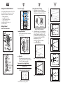
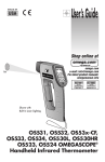
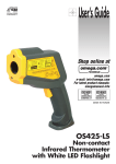
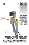
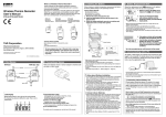
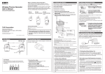
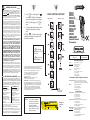
5
WARRANTY/DISCLAIMER
If the unit malfunctions, it must be returned to the factory for evaluation.
OMEGA’s Customer Service Department will issue an Authorized Return
(AR) number immediately upon phone or written request. Upon
examination by OMEGA, if the unit is found to be defective, it will be
repaired or replaced at no charge. OMEGA's WARRANTY does not apply
to defects resulting from any action of the purchaser, including but not
limited to mishandling, improper interfacing, operation outside of design
limits, improper repair, or unauthorized modification. This WARRANTY is
VOID if the unit shows evidence of having been tampered with or shows
evidence of having been damaged as a result of excessive corrosion; or
current, heat, moisture or vibration; improper specification;
misapplication; misuse or other operating conditions outside of
OMEGA’s control. Components in which wear are not warranted, include
but are not limited to contact points, fuses, and triacs.
OMEGA is pleased to offer suggestions on the use of its various
products. However, OMEGA neither assumes responsibility for any
omissions or errors nor assumes liability for any damages that
result from the use if its products in accordance with information
provided by OMEGA, either verbal or written. OMEGA warrants
only that the parts manufactured by the company will be as
specified and free of defects. OMEGA MAKES NO OTHER
WARRANTIES OR REPRESENTATIONS OF ANY KIND
WHATSOEVER, EXPRESSED OR IMPLIED, EXCEPT THAT OF TITLE,
AND ALL IMPLIED WARRANTIES INCLUDING ANY WARRANTY OF
MERCHANTABILITY AND FITNESS FOR A PARTICULAR PURPOSE
ARE HEREBY DISCLAIMED. LIMITATION OF LIABILITY: The
remedies of purchaser set forth herein are exclusive, and the total
liability of OMEGA with respect to this order, whether based on
contract, warranty, negligence, indemnification, strict liability or
otherwise, shall not exceed the purchase price of the component
upon which liability is based. In no event shall OMEGA be liable for
consequential, incidental or special damages.
CONDITIONS: Equipment sold by OMEGA is not intended to be used, nor
shall it be used: (1) as a “Basic Component” under 10 CFR 21 (NRC), used in
or with any nuclear installation or activity; or (2) in medical applications or
used on humans. Should any Product(s) be used in or with any nuclear
installation or activity, medical application, used on humans, or misused in
any way, OMEGA assumes no responsibility as set forth in our basic
WARRANTY/DISCLAIMER language, and, additionally, purchaser will
indemnify OMEGA and hold OMEGA harmless from any liability or damage
whatsoever arising out of the use of the Product(s) in such a manner.
RETURN REQUESTS/INQUIRIES
Direct all warranty and repair requests/inquiries to the OMEGA Customer
Service Department. BEFORE RETURNING ANY PRODUCT(S) TO OMEGA,
PURCHASER MUST OBTAIN AN AUTHORIZED RETURN (AR) NUMBER
FROM OMEGA’S CUSTOMER SERVICE DEPARTMENT (IN ORDER TO
AVOID PROCESSING DELAYS). The assigned AR number should then be
marked on the outside of the return package and on any correspondence.
FOR WARRANTY RETURNS,
please have the following
information available BEFORE
contacting OMEGA:
1. Purchase Order number under
which the product was
PURCHASED,
2. Model and serial number of
the product under warranty, and
3. Repair instructions and/or
specific problems relative to
the product.
FOR NON-WARRANTY REPAIRS,
consult OMEGA for current repair
charges. Have the following
information available BEFORE
contacting OMEGA:
1. Purchase Order number to cover
the COST of the repair or
calibration,
2. Model and serial number of the
product, and
3. Repair instructions and/or specific
problems relative to the product.
OMEGA’s policy is to make running changes, not model changes,
whenever an improvement is possible. This affords our customers the
latest in technology and engineering.
OMEGA is a registered trademark of OMEGA ENGINEERING, INC.
© Copyright 2006 OMEGA ENGINEERING, INC. All rights reserved.
This document may not be copied, photocopied, reproduced, translated, or
reduced to any electronic medium or machine-readable form, in whole or in
part, without the prior written consent of OMEGA ENGINEERING, INC.
MQS2891-0903
3.
pulled. To unlock the trigger, press the
again.
QUICK START
VISUAL FUNCTION FLOW CHART
Press the
key to lock the trigger. The
icon will appear. This allows the thermometer to
operate continuously whether or not the trigger is
MODE
key
DISPLAY
DISPLAY
LCK
LCK
MODE
LCK
LAL
4.
To complete a temperature measurement, release
the trigger; the thermometer goes into sleep
mode.
NOTE: If the
icon flashes and the unit beeps
intermittently, the batteries must be replaced with
fresh batteries immediately.
☞
☞
LCK
LCK
ATC
☞
OS531
OS532
OS533
OS534
OS530L
OS530HR
OS53x-CF
OS523
OS524
OMEGASCOPE®
☞
Handheld Infrared
Thermometer
LCK
LCK
PRN
While in these 5 modes:
☞
Use
key to change
temperature from °F to °C
or vice versa.
☞
(Model OS533)
For latest product manuals: omegamanual.info
LCK
LCK
Use
key to turn on the
display backlighting.
☞
OMEGAnet ® On-Line Service
omega.com
☞
LCK
It is the policy of OMEGA Engineering, Inc. to comply with all worldwide safety
and EMC/EMI regulations that apply. OMEGA is constantly pursuing
certification of its products to the European New Approach Directives. OMEGA
will add the CE mark to every appropriate device upon certification.
☞
The information contained in this document is believed to be
correct but OMEGA Engineering, Inc. accepts no liability for
any errors it contains, and reserves the right to alter
specifications without notice.
WARNING: These products are not designed for use in, and
should not be used for, human applications.
Canada:
LCK
LCK
U.S.A. and Canada: Sales Service: 1-800-826-6342/1-800-TC-OMEGA®
Customer Service: 1-800-622-2378/1-800-622-BEST®
Engineering Service: 1-800-872-9436/1-800-USA-WHEN®
HAL
Mexico:
☞
(Model OS531, OS532
OS530L, OS530HR)
Use of controls or adjustments
or performance of procedures
other than those specified here
may result in hazardous
radiation exposure. Refer to the
Operator’s Manual for complete
warnings and cautions.
CAUTION
®
OMEGASCOPE
LASER RADIATION - DO NOT STARE INTO BEAM
OUTPUT <1 mW, WAVELENGTH 630-670 nm
CLASS II (2) LASER PRODUCT, COMPLIES
WITH FDA 21CFR 1040.10 & EN60825-1/11.2001
Warning and
Certification
Label
En Espan˜ol: (001) 203-359-7803
FAX: (001) 203-359-7807
e-mail: [email protected]
[email protected]
Servicing Europe:
Czech Republic:
CAUTION:
One Omega Drive, P.O. Box 4047
Stamford. CT 06907-0047
Tel: (203) 359-1660
FAX: (203) 359-7700
e-mail: [email protected]
976 Bergar
Laval (Quebec) H7L 5A1, Canada
Tel: (514) 856-6928
FAX: (514) 856-6886
e-mail: [email protected]
For immediate technical or application assistance:
☞
PATENT NOTICE: U.S. PAT. D357,194, B1 5,368,392, 5,524,984, 5,727,880,
5,465,838 5,823,678, 5,823,679, 6,267,500B1, 6,123,453, 6,341,891B1/Canada
75811 D OMEGA ENGINEERING, INC., 2,116,055, 2,114,806/Czech Republic
25372/France 0378411 to 0378446, 2,767,921, 2 773 213 B1/Germany M 94 06
478.4, G 94 22 197.9, G 94 22 203.7/Italy RM940000913/Japan 988,378/
Netherlands 1007752, 25009-00/Spain mod. ut. 133292/Slovak Republic
24565/U.K. Registered 2041153, 9726133.3, EPO 0 644408, EP 1 085 307 A1
Other U.S. and International Patents Pending.
Internet e-mail
[email protected]
Servicing North America:
U.S.A.:
ISO 9001 Certified
AVOID EXPOSURE
LASER RADIATION
IS EMITTED FROM
THIS APERTURE
OMEGA ENGINEERING, INC. warrants this unit to be free of defects in
materials and workmanship for a period of 25 months from date of
purchase of the base unit and 13 months from date of purchase on
Laser Sight Module. OMEGA’s WARRANTY adds an additional one (1)
month grace period to the normal one (1) year product warranty to
cover handling and shipping time. This ensures that OMEGA’s
customers receive maximum coverage on each product.
6
Frystatska 184, 733 01 Karviná, Czech Republic
Tel: +420 (0)59 6311899
FAX: +420 (0)59 6311114
Toll Free: 0800-1-66342
e-mail: [email protected]
Germany/Austria: Daimlerstrasse 26, D-75392 Deckenpfronn, Germany
Tel: +49 (0)7056 9398-0
FAX: +49 (0)7056 9398-29
Toll Free in Germany: 0800 639 7678
e-mail: [email protected]
United Kingdom: One Omega Drive, River Bend Technology Centre
Northbank, Irlam, Manchester
ISO 9002 Certified
M44 5BD United Kingdom
Tel: +44 (0)161 777 6611
FAX: +44 (0)161 777 6622
Toll Free in United Kingdom: 0800-488-488
e-mail: [email protected]
2
Getting Started
Parts of the Thermometer
1.
Backlighting
Icon
LCK
ATC
HAL LOBAT
LAL PRN °F °C
Aim at the target. If you are not using the Laser
Sighting, use the “V” groove on top of the thermometer
to align the target to the thermometer’s field of view.
Field of View
Unit of
Measure
Main Display
Temperature
Scrolls
through
Display
Modes
Locks
Trigger/
Enables
Alarms
Decrements
Data/
°F to °C or
°C to °F
Increments
Data/
Backlighting
ON/OFF
Target
(ACCEPTABLE)
Figure 6. Field of View Positions
Figure 3. Display and Keypad View
Installing the Batteries
Invert the unit and install 4 fresh AA size batteries
as shown in Figure 4.
(UNACCEPTABLE)
2.
Pull and hold the trigger. To use the laser sighting, set
the laser power switch to the ON position. The Power
Indicator LED and the laser beam will turn on. The
laser beam will stay on as long as the trigger is pulled.
The target temperature and emissivity (E) will be
displayed on the LCD. You can
press the
or
key to increment or
decrement the target emissivity.
)
Display
Icons
Data
Associated with
Display Mode
Figure 9. OS534/OS523-1 Field of View
DISTANCE: SENSOR LENS TO OBJECT (in.)
0
SPOT DIA.* (IN)
• Installing the Batteries
• Operating the Laser Sight
• Taking Temperature Readings
• Display Mode Sequence
For detailed information, refer to the
User’s Guide (M2891).
Display
Mode
6"
3"
9"
15"
12"
1.17"
0.9"
.45"
.15"
11.5
3.9
.39"
.78"
D:S = 40:1
SPOT DIA.* )(MM)
Use this Quick Start Manual with your OS530/OS520
series Handheld Infrared Thermometer to set it up
and perform basic operations. These tasks are:
Taking Temperature Readings
Parts of the Display
22
9.9
19.9
29.9
*SPOT DIAMETER MEASURED
AT 90% ENERGY
7.6
0
22.9
15.2
38.1
30.5
DISTANCE: SENSOR LENS TO OBJECT (cm.)
Figure 10. OS53x-CF Field of View
DISTANCE: SENSOR TO OBJECT (FT)
SPOT DIA.* (IN)
Using this Quick Start Manual
4
3
** Measurement distance is from the outside surface of the rubber boot.
START HERE
3'
0'
5'
10'
16'
2.9"
1.9"
0.9"@ 0
1.2"
1.0"
0.9"
D:S = 60:1
)
SPOT DIA.* (MM)
26
31
22mm @ 0
48
*SPOT DIAMETER MEASURED
AT 90% ENERGY
0
1.0
75
1.5
3.0
5.0
DISTANCE: SENSOR TO OBJECT (M)
Figure 11. OS523-2 Field of View
Figure 1. Front of the Thermometer
)
DISTANCE: SENSOR TO OBJECT (FT)
ac Operation
Analog Output Jack (1mV/deg)
RS-232 Phone Jack
(OS533, OS534,
OS523, OS524)
Identification Label
(bottom)
Tripod Thread
Mount
10’
4.0"
.9"
22
21
3'
4'
5'
7'
4.2"
8'
4.8"
3.6"
1.0" @ 0" to 20"
3.0"
2.4"
1.0"
7.0"
1.6"
42
101
6'
16’
181
9mm @ 610mm
)
20" 2'
1'
1.0"
WARNING: DO NOT AIM THE LASER BEAM AT
ANYONE’S EYES.
5’
.35"@ 24"
.8"
SPOT DIA.* (MM)
Operating the Laser Sight Module
ac Adapter Input Jack
3’
2’
DISTANCE: SENSOR TO OBJECT (FT)
0**
SPOT DIA.* (IN)
Thermocouple Input
Socket (SMP)
0’
Figure 7. OS531, OS532, OS530L Field of View
*SPOT DIAMETER MEASURED
AT 90% ENERGY
0
.61
1.0
1.8"
1.2"
1.5
3.0
5.0
DISTANCE: SENSOR TO OBJECT (M)
Figure 12. OS523-3 Field of View
D:S = 20:1
DISTANCE: SENSOR TO OBJECT (FT)
The laser sight module is built into the thermometer.
Set the laser power switch to the ON position.
2 Types of Laser Beams
2.5
4.0
SPOT DIA.* (CM)
Laser Beam
Aperture
The thermometer may be operated on ac power
using the optional ac adapter. 120Vac/60 Hz and
220Vac/50 Hz adapters are available.
6.0
8.0
2.5cm @ 51cm
10.0
*SPOT DIAMETER MEASURED
AT 90% ENERGY
40
80
120
12.2
160
200
SPOT DIA.* (IN)
Laser
Dot/Circle
Switch
SPOT DIA.* (IN)
Figure 4. Installing the Batteries
0'
16'
8.7"
1.5"
5.1"
DISTANCE: SENSOR TO OBJECT (CM)
Figure 2. Rear of the Thermometer
D:S = 110:1
Figure 8. OS533, OS530HR Field of View
Laser Circle
Figure 5. Two Laser Configurations
The thermometer is ready for operation.
38
SPOT DIA.* (MM)
)
Laser Dot
82'
0.5"@ 0
0.9"
244
50'
130
221
15
25
13mm @ 0
*SPOT DIAMETER MEASURED
AT 90% ENERGY
0
5
DISTANCE: SENSOR TO OBJECT (M)