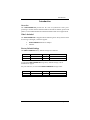
1
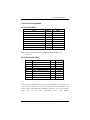
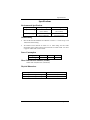
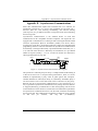
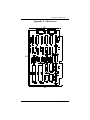
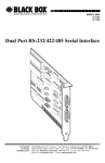
User’s Guide
Shop online at
www.omega.com
e-mail: [email protected]
OMG-COMM2-EX
Dual Port ISA RS-232/422/485 Interface Board
OMEGAnet ® Online Service
www.omega.com
Internet e-mail
[email protected]
Servicing North America:
USA:
ISO 9001 Certified
Canada:
One Omega Drive, P.O. Box 4047
Stamford CT 06907-0047
TEL: (203) 359-1660
e-mail: [email protected]
976 Bergar
Laval (Quebec) H7L 5A1, Canada
TEL: (514) 856-6928
e-mail: [email protected]
FAX: (203) 359-7700
FAX: (514) 856-6886
For immediate technical or application assistance:
USA and Canada: Sales Service: 1-800-826-6342 / 1-800-TC-OMEGA®
Customer Service: 1-800-622-2378 / 1-800-622-BEST®
Engineering Service: 1-800-872-9436 / 1-800-USA-WHEN®
TELEX: 996404 EASYLINK: 62968934 CABLE: OMEGA
Mexico:
En Espan˜ol: (001) 203-359-7803
FAX: (001) 203-359-7807
e-mail: [email protected]
[email protected]
Servicing Europe:
Benelux:
Postbus 8034, 1180 LA Amstelveen, The Netherlands
TEL: +31 (0)20 3472121
FAX: +31 (0)20 6434643
Toll Free in Benelux: 0800 0993344
e-mail: [email protected]
Czech Republic:
Frystatska 184, 733 01 Karviná, Czech Republic
TEL: +420 (0)59 6311899
FAX: +420 (0)59 6311114
Toll Free: 0800-1-66342
e-mail: [email protected]
France:
11, rue Jacques Cartier, 78280 Guyancourt, France
TEL: +33 (0)1 61 37 29 00
FAX: +33 (0)1 30 57 54 27
Toll Free in France: 0800 466 342
e-mail: [email protected]
Germany/Austria: Daimlerstrasse 26, D-75392 Deckenpfronn, Germany
TEL: +49 (0)7056 9398-0
Toll Free in Germany: 0800 639 7678
e-mail: [email protected]
United Kingdom:
ISO 9002 Certified
FAX: +49 (0)7056 9398-29
One Omega Drive, River Bend Technology Centre
Northbank, Irlam, Manchester
M44 5BD United Kingdom
TEL: +44 (0)161 777 6611
FAX: +44 (0)161 777 6622
Toll Free in United Kingdom: 0800-488-488
e-mail: [email protected]
It is the policy of OMEGA to comply with all worldwide safety and EMC/EMI regulations that
apply. OMEGA is constantly pursuing certification of its products to the European New Approach
Directives. OMEGA will add the CE mark to every appropriate device upon certification.
The information contained in this document is believed to be correct, but OMEGA Engineering, Inc. accepts
no liability for any errors it contains, and reserves the right to alter specifications without notice.
WARNING: These products are not designed for use in, and should not be used for, patient-connected applications.
Contents
INTRODUCTION..........................................................................1
OVERVIEW................................................................................................ 1
W HAT ’S INCLUDED ................................................................................ 1
FACTORY DEFAULT SETTINGS ............................................................ 1
CARD SETUP ..............................................................................2
A DDRESS SELECTION............................................................................. 2
PORT ENABLE / DISABLE....................................................................... 3
INTERFACE SELECTION......................................................................... 3
RS-422/485 ............................................................................................ 3
RS-232.................................................................................................... 3
IRQ SELECTION ...................................................................................... 3
INTERRUPT M ODES................................................................................ 4
HEADERS E3 AND E4............................................................................... 5
INSTALLATION ..........................................................................6
OPERATING SYSTEM INSTALLATION ................................................. 6
For Windows Users ............................................................................ 6
Other Operating Systems ................................................................... 6
TECHNICAL DESCRIPTION .........................................................7
FEATURES ................................................................................................ 7
M ODEM CONTROL SIGNAL CONSIDERATIONS.................................. 7
LINE TERMINATION ............................................................................... 7
CONNECTOR PIN A SSIGNMENTS.......................................................... 8
RS-232 (Male DB9) .............................................................................. 8
RS-422/485 (Male DB9)....................................................................... 8
SPECIFICATIONS ........................................................................9
ENVIRONMENTAL SPECIFICATIONS.................................................... 9
M ANUFACTURING .................................................................................. 9
POWER CONSUMPTION.......................................................................... 9
M EAN TIME BETWEEN FAILURES (MTBF) ....................................... 9
PHYSICAL DIMENSIONS.......................................................................... 9
APPENDIX A - TROUBLESHOOTING .........................................10
APPENDIX B - How To Get Assistance.........................................11
APPENDIX C - ELECTRICAL INTERFACE...................................12
RS-232..................................................................................................... 12
RS-422..................................................................................................... 12
RS-485..................................................................................................... 13
APPENDIX D - ASYNCHRONOUS COMMUNICATIONS ...............14
APPENDIX E - SILK-SCREEN ....................................................15
APPENDIX F - COMPLIANCE NOTICES ...................................16
FEDERAL COMMUNICATIONS COMMISSION STATEMENT ............ 16
EMC DIRECTIVE STATEMENT ........................................................... 16
Figures
Figure 1 - Address Selection Table ....................................................................2
Figure 2 - DIP-Switch Illustration......................................................................2
Figure 3 - Header E1 and E2, IRQ Selection.....................................................3
Figure 4 - Headers E9 and E10, Normal IRQ Mode .........................................4
Figure 5 - Headers E9 and E10, Shared IRQ Mode ..........................................4
Figure 6 - Headers E9 and E10, Sharing IRQ’s with another adapter .........5
Figure 7 - Asynchronous Communications Bit Diagram.............................14
Introduction
Introduction
Overview
The OMG-COMM2-EX provides the PC with 2 asynchronous serial ports
providing a versatile interface field selectable as RS-232 for modems, printers and
plotters, as well as RS-422/485 for industrial automation and control applications.
What’s Included
The OMG-COMM2-EX is shipped with the following items. If any of these items
are missing or damaged, contact the supplier.
•
•
OMG-COMM2-EX Serial I/O Adapter
Software
Factory Default Settings
The OMG-COMM2-EX factory default settings are as follows:
Port #
Port 1
Port 2
Base Address
280
288
IRQ
5
10
Electrical Interface
RS-422
RS-422
To install the OMG-COMM2-EX using factory default settings, refer to
Installation on page 6.
For your reference, record installed OMG-COMM2-EX settings below:
Port #
Base Address
OMG-COMM2-EX
IRQ
Electrical Interface
Page 1
Card Setup
Card Setup
The OMG-COMM2-EX contains several jumper straps which must be set for
proper operation.
Address Selection
Each port on the OMG-COMM2-EX occupies eight consecutive I/O locations. A
DIP-switch is used to set the base address for these locations. Be careful when
selecting the base address as some selections conflict with existing ports. The
following table shows several examples that typically do not cause a conflict.
SW1 sets the I/O address for port 1 of the OMG-COMM2-EX and SW2 sets the
address for port 2.
Address
Hex
280-287
2A0-2A7
2E8-2EF
2F8-2FF
3E8-3EF
300-307
328-32F
3F8-3FF
Binary
A9
A0
1010000XXX
1010100XXX
1011101XXX
1011111XXX
1111101XXX
1100000XXX
1100101XXX
1111111XXX
Switch Position Setting
2
3
4
5
6
On Off On
On
On
On Off On Off
On
On Off Off Off
On
On Off Off Off
Off
Off Off Off Off
On
Off On On
On
On
Off On On Off
On
Off Off Off Off
Off
1
Off
Off
Off
Off
Off
Off
Off
Off
7
On
On
Off
Off
Off
On
Off
Off
Figure 1 - Address Selection Table
The following illustration shows the correlation between the DIP-switch setting
and the address bits used to determine the base address. In the example below,
address 300 is selected as a base. Address 300 in binary is XX11 0000 0XXX
where X = a non-selectable address bit.
A9
A3 EN
ON
1
2
3
4
5
6
7
8
Figure 2 - DIP-Switch Illustration
Note: Setting the switch ‘On’ or ‘Closed’ corresponds to a ‘0’ in the address,
while leaving it ‘Off’ or ‘Open’ corresponds to a ‘1’.
Refer to Appendix A for common address contentions.
OMG-COMM2-EX
Page 2
Card Setup
Port Enable / Disable
Each port on the OMG-COMM2-EX can be enabled or disabled with switch
position 8 on the DIP-switch. The port is enabled with the switch ‘On’ or
‘Closed’ and disabled when ‘Off’ or ‘Open’. If any port is disabled, be sure to
disable the interrupt request for that port by removing the IRQ jumper.
Interface Selection
RS-422/485
To select the RS-422/485 mode of operation install dip shunts in sockets found at
E6 and E7. E6 sets Port 1 and E7 sets Port 2.
RS-232
To select the RS-232 mode of operation install dip shunts in sockets found at E5
and E8. E5 sets Port 1 and E8 sets Port 2.
IRQ Selection
Headers E1 and E2 select the interrupt request for each serial port (E1 - Port 2, E2
- Port 1). If COM1: is selected, the corresponding jumper must be on the IRQ4
setting. If COM2: is selected, the corresponding jumper must be on IRQ3.
E1
2/9 3 4 5 7 10 11 12 15
E2
2/9 3 4 5 7 10 11 12 15
Figure 3 - Header E1 and E2, IRQ Selection
Any two or more ports can share a common IRQ, provided a polling driver is
used, by placing the jumpers on the same IRQ setting and setting the appropriate
selections at E3. The following examples show the setup if a polling driver is
used. NOTE: Windows does not provide a polling driver. Consult your particular
software for IRQ selection. If no interrupt is desired, remove the jumper.
OMG-COMM2-EX
Page 3
Card Setup
Interrupt Modes
Headers E9 and E10 select the interrupt modes for each port. Each port must be
set in the correct mode to insure proper installation. E10 sets Port 1 and E9 sets
Port 2
E10
‘N’ indicates the (N)ormal, single interrupt per port mode. ‘S’ Indicates the
(S)hared interrupt mode, which allows more than one port to access a single IRQ.
Any two or more ports can share a common IRQ by placing the jumpers on the
same IRQ setting, and setting the appropriate selections at E1. Consult your
particular software for IRQ selection. If no interrupt is desired, remove the
jumper. ‘M’ indicates the inclusion of a 1K ohm pull-down resistor required on
one port when sharing interrupts.
S
M
S
M
E9
N
N
Figure 4 - Headers E9 and E10, Normal IRQ Mode
E10
Set the jumpers to ‘S’ for shared interrupt mode on all blocks sharing an IRQ
except one. Set that port block for ‘M’. This provides the pull-down resistor
circuit that makes sharing of IRQs possible. If you are using more than one
OMG-COMM2-EX or a compatible adapter in a bus you should only have one
port set to ‘M’. The following example shows both ports sharing a single IRQ.
S
M
N
S
M
E9
N
Figure 5 - Headers E9 and E10, Shared IRQ Mode
OMG-COMM2-EX
Page 4
Card Setup
E10
Set the jumper to ‘S’ if you are using more than one OMG-COMM2-EX in a bus
or you wish to completely remove the pull-down resistor for hardware
compatibility. Setting the adapter in this configuration when it is not
accompanied by a pull-down resistor will prevent the ports from triggering an
interrupt.
S
M
N
S
M
E9
N
Figure 6 - Headers E9 and E10, Sharing IRQ’s with another adapter
Headers E3 and E4
Position ‘A’ Determines whether the RS-485 driver is enabled by the UART
signal Request To Send (RTS) or always enabled. With the jumper installed in
position ‘A’, RTS enables the driver. Removing the jumper enables the driver
regardless of RTS. E4 sets Port 1 while E3 sets Port 2. This jumper should only
be set to ‘A’ if you are running the board in a multi-drop polled environment
such as RS-485, and you have software that ‘knows how to talk’ on the RS-485
bus. For normal point-to-point RS-422 (such as terminal emulation), make sure
that a jumper at position ‘A’ is not in place.
Positions ‘B’ & ‘C’ determine whether the board provides a direct ground
connection (as in RS-232 and most RS-422), or a 100 ohm high impedance
ground. The high impedance ground is normally used by RS-485 (and some RS422) to avoid ground loop currents with long cables. Position ‘B’ selects the
direct ground and position ‘C’ selects the 100 ohm high impedance ground.
A B C
A B C
Figure 7 - Headers E3 and E4 (Factory Default
OMG-COMM2-EX
Page 5
Installation
Installation
The OMG-COMM2-EX can be installed in any of the PC expansion slots, but to
access the ‘AT’ or (E)ISA IRQs (10 - 15) it must be installed in one of the 16 bit
slots. The OMG-COMM2-EX contains several jumper straps for each port which
must be set for proper operation prior to installing the adapter into the comp uter.
1.
2.
3.
4.
Turn off PC power. Disconnect the power cord.
Remove the PC case cover.
Locate an available slot and remove the blank metal slot cover.
Gently insert the OMG-COMM2-EX into the slot. Make sure that the
adapter is seated properly.
5. Replace the screw.
6. Replace the cover.
7. Connect the power cord.
Installation is complete.
Operating System Installation
For Windows Users
Start by choosing Install Software at the beginning of the CD. Choose
Asynchronous COM: Port Software, SeaCOM.
Other Operating Systems
Refer to the appropriate section of the Serial Utilities Software.
OMG-COMM2-EX
Page 6
Technical Description
Technical Description
The OMG-COMM2-EX adapter utilizes the 16550 UART chip. This chip features
programmable baud rate, data format, interrupt control and has a 16 byte transmit
and receive FIFO.
Features
•
Full independent operation of ports allowing two ports RS-232, two ports
RS-422/485 or one port of each.
•
Addressable as COM1: - COM4: or any other I/O address up to 3FF Hex.
•
‘Shareable’ IRQs allow more than one port to share a single IRQ provided
the proper driver is used..
•
IRQs 2/9-5, 7, 10, 11, 12, 15 supported
•
Support for non-standard baud rates available. These baud rates (such as
31.25K or 76.8K baud) are supported by installing a different oscillator.
Please consult Technical Support for more information.
Modem Control Signal Considerations
Some software packages require the use of the modem handshake signals such
as CTS or DCD. Refer to your application software manual to determine the
requirements for modem control signals. If no requirements are mentioned, a safe
configuration is to tie DTR to DSR and DCD, and tie RTS to CTS. This
configuration will typically satisfy the modem control signal requirements for
most communications software.
Line Termination
Typically, each end of the RS-422/485 bus must have line terminating resistors. A
100 ohm resistor is across each RS-422/485 input and a 1K ohm pull-up/pulldown combination bias the receiver inputs. If more than two RS-485 nodes are
configured in a multi-drop network, only the nodes at each end of the bus should
have the 100 ohm resistors installed.
OMG-COMM2-EX
Page 7
Technical Description
Connector Pin Assignments
RS-232 (Male DB9)
TD
RTS
DTR
GND
RD
DCD
DSR
CTS
RI
Name
Transmit Data
Request To Send
Data Term Ready
Ground
Receive Data
Data Carrier Detect
Data Set Ready
Clear To Send
Ring Indicator
Pin #
3
7
4
5
2
1
6
8
9
Mode
Output
Output
Output
Input
Input
Input
Input
Input
Note: These assignments meet EIA/TIA/ANSI-574 DTE for DB-9 type
connectors.
RS-422/485 (Male DB9)
Signal
GND
TX +
TXRTS+
RTSRX+
RXCTS+
CTS-
Name
Ground
Transmit Data Positive
Transmit Data Negative
Request To Send Positive
Request To Send Negative
Receive Data Positive
Receive Data Negative
Clear To Send Positive
Clear To Send Negative
Pin #
5
4
3
6
7
1
2
9
8
Mode
Output
Output
Output
Output
Input
Input
Input
Input
Technical Note: Please terminate any control signals that are not going to be
used. The most common way to do this is connect RTS to CTS and RI. Also,
connect DCD to DTR and DSR. Terminating these pins, if not used, will help
insure
you
get
the
best
performance
from
your
adapter.
OMG-COMM2-EX
Page 8
Specifications
Specifications
Environmental Specifications
Specification
Temperature Range
Humidity Range
Operating
0º to 50º C
(32º to 122º F)
10 to 90% R.H.
Non-Condensing
Storage
-20º to 70º C
(-4º to 158º F)
10 to 90% R.H.
Non-Condensing
Manufacturing
•
IPC 610-B Class-III standards are adhered to with a 0.1 visual A.Q.L. and
100% Functional Testing.
•
All Printed Circuit boards are built to U.L. 94V0 rating and are 100%
electrically tested. These printed circuit boards are solder mask over bare
copper or solder mask over tin nickel.
Power Consumption
Supply line
Rating
+12 VDC
50 mA
-12 VDC
50 mA
+5 VDC
195 mA
Mean Time Between Failures (MTBF)
Greater than 150,000 hours. (Calculated)
Physical Dimensions
Board length
Board Height including Goldfingers
Board Height excluding Goldfingers
OMG-COMM2-EX
6.9 inches
4.2 inches
3.9 inches
(17.53 cm)
(8.89 cm)
(8.13 cm)
Page 9
Appendix A - Troubleshooting
Appendix A - Troubleshooting
Serial Utility test software is supplied with the adapter and will be used in the
troubleshooting procedures. By using this software and following these simple
steps, most common problems can be eliminated without the need to call
Technical Support.
1.
Identify all I/O adapters currently installed in your system. This includes
your on-board serial ports, controller cards, sound cards etc. The I/O
addresses used by these adapters, as well as the IRQ (if any) should be
identified.
2.
Configure your adapter so that there is no conflict with currently installed
adapters. No two adapters can occupy the same I/O address.
3.
Make sure the adapter is using a unique IRQ The IRQ is typically selected
via an on-board header block. Refer to the section on Card Setup for help in
choosing an I/O address and IRQ.
4.
Make sure the adapter is securely installed in a motherboard slot.
5.
When running DOS, Windows 3.x or other operating systems refer to the
Serial Utilities software for that operating system and the User Manual to
verify that the adapter is configured correctly. The supplied software
contains a diagnostic program 'SSD' that runs under DOS and will verify if an
adapter is configured properly. This diagnostic program is written with the
user in mind and is easy to use. Refer to the DIAG.txt file in the dos\diag
directory for detailed instructions on using 'SSD'.
6.
For Windows 95/98 and Windows NT, the diagnostic tool 'WinSSD' is
installed in the Omega Engineering folder on the Start Menu during the
setup process. First find the ports using the Device Manager, then use
'WinSSD' to verify that the ports are functional.
7.
Always use the diagnostic software when troubleshooting a problem. This
will help eliminate any software issues and identify any hardware conflicts.
OMG-COMM2-EX
Page 10
Appendix B - How To Get Assistance
Appendix B - How To Get Assistance
Please refer to Troubleshooting Guide prior to calling Technical Support.
1.
Begin by reading through the Trouble Shooting Guide in Appendix
A. If assistance is still needed please see below.
2.
When calling for technical assistance, please have your user
manual and current adapter settings. If possible, please have the
adapter installed in a computer ready to run diagnostics.
3.
Omega Engineering maintains a Home page on the Internet. Our
home page address is www.omega.com. The latest software
updates , and newest manuals are available via our FTP site that can
be accessed from our home page.
4.
Technical support is available Monday to Friday from 8:30 a.m. to
6:00 p.m. eastern time. Technical support can be reached at 1-800DAS-IEEE.
RETURN AUTHORIZATION MUST BE OBTAINED FROM OMEGA
ENGINEERING BEFORE RETURNED MERCHANDISE WILL BE ACCEPTED.
AUTHORIZATION CAN BE OBTAINED BY CALLING OMEGA CUSTOMER
SERVICE AND REQUESTING AN AUTHORIZED RETURN (AR) NUMBER.
OMG-COMM2-EX
Page 11
Appendix C - Electrical Interface
Appendix C - Electrical Interface
RS-232
Quite possibly the most widely used communication standard is RS-232. This
implementation has been defined and revised several times and is often referred
to as RS-232 or EIA/TIA-232. The IBM PC computer defined the RS-232 port on a
9 pin D sub connector and subsequently the EIA/TIA approved this
implementation as the EIA/TIA-574 standard. This standard is defined as the
9-Position Non-Synchronous Interface between Data Terminal Equipment and
Data Circuit-Terminating Equipment Employing Serial Binary Data
Interchange. Both implementations are in wide spread use and will be referred to
as RS-232 in this document. RS-232 is capable of operating at data rates up to 20
Kbps at distances less than 50 ft. The absolute maximum data rate may vary due
to line conditions and cable lengths. RS-232 is a single ended or unbalanced
interface, meaning that a single electrical signal is compared to a common signal
(ground) to determine binary logic states. The RS-232 and the EIA/TIA-574
specification define two types of interface circuits, Data Terminal Equipment
(DTE) and Data Circuit-Terminating Equipment (DCE). The OMG-COMM2-EX is
a DTE device.
RS-422
The RS-422 specification defines the electrical characteristics of balanced voltage
digital interface circuits. RS-422 is a differential interface that defines voltage
levels and driver/receiver electrical specifications. On a differential interface,
logic levels are defined by the difference in voltage between a pair of outputs or
inputs. In contrast, a single ended interface, for examp le RS-232, defines the logic
levels as the difference in voltage between a single signal and a common ground
connection. Differential interfaces are typically more immune to noise or voltage
spikes that may occur on the communication lines. Differential interfaces also
have greater drive capabilities that allow for longer cable lengths. RS-422 is rated
up to 10 Megabits per second and can have cabling 4000 feet long. RS-422 also
defines driver and receiver electrical characteristics that will allow 1 driver and up
to 32 receivers on the line at once. RS-422 signal levels range from 0 to +5 volts.
RS-422 does not define a physical connector.
OMG-COMM2-EX
Page 12
Appendix C - Electrical Interface
RS-485
RS-485 is backwardly compatible with RS-422; however, it is optimized for
partyline or multi-drop applications. The output of the RS-422/485 driver is
capable of being Active (enabled) or Tri-State (disabled). This capability allows
multiple ports to be connected in a multi-drop bus and selectively polled. RS-485
allows cable lengths up to 4000 feet and data rates up to 10 Megabits per second.
The signal levels for RS-485 are the same as those defined by RS-422. RS-485 has
electrical characteristics that allow for 32 drivers and 32 receivers to be
connected to one line. This interface is ideal for multi-drop or network
environments. RS-485 tri-state driver (not dual-state) will allow the electrical
presence of the driver to be removed from the line. Only one driver may be active
at a time and the other driver(s) must be tri-stated. RS-485 can be cabled in two
ways, two wire and four wire mode. Two wire mode does not allow for full duplex
communication, and requires that data be transferred in only one direction at a
time. For half-duplex operation, the two transmit pins should be connected to the
two receive pins (Tx+ to Rx+ and Tx- to Rx-). Four wire mode allows full duplex
data transfers. RS-485 does not define a connector pin-out or a set of modem
control signals. RS-485 does not define a physical connector.
OMG-COMM2-EX
Page 13
Appendix D - Asynchronous Communications
Appendix D - Asynchronous Communications
Serial data communications implies that individual bits of a character are
transmitted consecutively to a receiver that assembles the bits back into a
character. Data rate, error checking, handshaking, and character framing
(start/stop bits) are pre-defined and must correspond at both the transmitting
and receiving ends.
Asynchronous communications is the standard means of serial data
communication for PC compatibles and PS/2 computers. The original PC was
equipped with a communication or COM: port that was designed around an 8250
Universal Asynchronous Receiver Transmitter (UART). This device allows
asynchronous serial data to be transferred through a simple and straightforward
programming interface. Character boundaries for asynchronous communications
are defined by a starting bit followed by a pre-defined number of data bits (5, 6, 7,
or 8). The end of the character is defined by the transmission of a pre-defined
number of stop bits (usually 1, 1.5 or 2). An extra bit used for error detection is
often appended before the stop bits.
Idle state of
line
5 to 8 Data Bits
Odd, Even
or
Unused
Remain Idle or
next start bit
1
P
BIT
STOP
0
1
1.5
2
Figure 8 - Asynchronous Communications Bit Diagram
This special bit is called the parity bit. Parity is a simple method of determining if
a data bit has been lost or corrupted during transmission. There are several
methods for implementing a parity check to guard against data corruption.
Common methods are called (E)ven Parity or (O)dd Parity. Sometimes parity is
not used to detect errors on the data stream. This is refereed to as (N)o parity.
Because each bit in asynchronous communications is sent consecutively, it is
easy to generalize asynchronous communications by stating that each character
is wrapped (framed) by pre-defined bits to mark the beginning and end of the
serial transmission of the character. The data rate and communication parameters
for asynchronous communications have to be the same at both the transmitting
and receiving ends. The communication parameters are baud rate, parity, number
of
data
bits
per
character,
and
stop
bits
(i.e. 9600,N,8,1).
OMG-COMM2-EX
Page 14
Appendix E - Silk-Screen
Appendix E - Silk-Screen
3.9"
6.9"
4.2"
OMG-COMM2-EX
Page 15
Appendix F - Compliance Notices
Appendix F - Compliance Notices
Federal Communications Commission Statement
FCC - This equipment has been tested and found to comply with the limits for
Class A digital device, pursuant to Part 15 of the FCC Rules. These limits are
designed to provide reasonable protection against harmful interference when the
equipment is operated in a commercial environment. This equipment generates,
uses, and can radiate radio frequency energy and, if not installed and used in
accordance with the instruction manual, may cause harmful interference to radio
communications. Operation of this equipment in a residential area is likely to
cause harmful interference in such case the user will be required to correct the
interference at his own expense.
EMC Directive Statement
Products bearing the CE Label fulfill the requirements of the
EMC directive (89/336/EEC) and of the low-voltage directive
(73/23/EEC) issued by the European Commission.
To obey these directives, the following European standards
must be met:
•
EN55022 Class A - “Limits and methods of measurement of radio
interference characteristics of information technology equipment”
•
EN55024-‘Information
technology
equipment
characteristics Limits and methods of measurement.
Immunity
•
EN60950 (IEC950) - “Safety of information
equipment, including electrical business equipment”
technology
Warning
This is a Class A Product. In a domestic environment this product may cause
radio interference in which case the user may be required to take adequate
measures.
Always use cabling provided with this product if possible. If no cable is
provided or if an alternate cable is required, use high quality shielded cabling to
maintain compliance with FCC/EMC directives.
OMG-COMM2 -EX
Page 16
WARRANTY/DISCLAIMER
OMEGA ENGINEERING, INC. warrants this unit to be free of defects in materials and workmanship for a
period of 13 months from date of purchase. OMEGA’s WARRANTY adds an additional one (1) month
grace period to the normal one (1) year product warranty to cover handling and shipping time. This
ensures that OMEGA’s customers receive maximum coverage on each product.
If the unit malfunctions, it must be returned to the factory for evaluation. OMEGA’s Customer Service
Department will issue an Authorized Return (AR) number immediately upon phone or written request.
Upon examination by OMEGA, if the unit is found to be defective, it will be repaired or replaced at no
charge. OMEGA’s WARRANTY does not apply to defects resulting from any action of the purchaser, including but not limited to mishandling, improper interfacing, operation outside of design limits,
improper repair, or unauthorized modification. This WARRANTY is VOID if the unit shows evidence of
having been tampered with or shows evidence of having been damaged as a result of excessive corrosion;
or current, heat, moisture or vibration; improper specification; misapplication; misuse or other operating
conditions outside of OMEGA’s control. Components which wear are not warranted, including but not
limited to contact points, fuses, and triacs.
OMEGA is pleased to offer suggestions on the use of its various products. However,
OMEGA neither assumes responsibility for any omissions or errors nor assumes liability for any
damages that result from the use of its products in accordance with information provided by
OMEGA, either verbal or written. OMEGA warrants only that the parts manufactured by it will be
as specified and free of defects. OMEGA MAKES NO OTHER WARRANTIES OR
REPRESENTATIONS OF ANY KIND WHATSOEVER, EXPRESS OR IMPLIED, EXCEPT THAT OF TITLE,
AND ALL IMPLIED WARRANTIES INCLUDING ANY WARRANTY OF MERCHANTABILITY AND
FITNESS FOR A PARTICULAR PURPOSE ARE HEREBY DISCLAIMED. LIMITATION OF
LIABILITY: The remedies of purchaser set forth herein are exclusive, and the total liability of
OMEGA with respect to this order, whether based on contract, warranty, negligence,
indemnification, strict liability or otherwise, shall not exceed the purchase price of the
component upon which liability is based. In no event shall OMEGA be liable for
consequential, incidental or special damages.
CONDITIONS: Equipment sold by OMEGA is not intended to be used, nor shall it be used: (1) as a “Basic
Component” under 10 CFR 21 (NRC), used in or with any nuclear installation or activity; or (2) in medical
applications or used on humans. Should any Product(s) be used in or with any nuclear installation or
activity, medical application, used on humans, or misused in any way, OMEGA assumes no responsibility
as set forth in our basic WARRANTY/ DISCLAIMER language, and, additionally, purchaser will indemnify
OMEGA and hold OMEGA harmless from any liability or damage whatsoever arising out of the use of the
Product(s) in such a manner.
RETURN REQUESTS/INQUIRIES
Direct all warranty and repair requests/inquiries to the OMEGA Customer Service Department. BEFORE
RETURNING ANY PRODUCT(S) TO OMEGA, PURCHASER MUST OBTAIN AN AUTHORIZED RETURN
(AR) NUMBER FROM OMEGA’S CUSTOMER SERVICE DEPARTMENT (IN ORDER TO AVOID
PROCESSING DELAYS). The assigned AR number should then be marked on the outside of the return
package and on any correspondence.
The purchaser is responsible for shipping charges, freight, insurance and proper packaging to prevent
breakage in transit.
FOR WARRANTY RETURNS, please have the
following information available BEFORE
contacting OMEGA:
1. Purchase Order number under which the product
was PURCHASED,
2. Model and serial number of the product under
warranty, and
3. Repair instructions and/or specific problems
relative to the product.
FOR NON-WARRANTY REPAIRS, consult OMEGA
for current repair charges. Have the following
information available BEFORE contacting OMEGA:
1. Purchase Order number to cover the COST
of the repair,
2. Model and serial number of the product, and
3. Repair instructions and/or specific problems
relative to the product.
OMEGA’s policy is to make running changes, not model changes, whenever an improvement is possible. This affords
our customers the latest in technology and engineering.
OMEGA is a registered trademark of OMEGA ENGINEERING, INC.
© Copyright 2002 OMEGA ENGINEERING, INC. All rights reserved. This document may not be copied, photocopied,
reproduced, translated, or reduced to any electronic medium or machine-readable form, in whole or in part, without the
prior written consent of OMEGA ENGINEERING, INC.
Where Do I Find Everything I Need for
Process Measurement and Control?
OMEGA…Of Course!
Shop online at www.omega.com
TEMPERATURE
Thermocouple, RTD & Thermistor Probes, Connectors, Panels & Assemblies
Wire: Thermocouple, RTD & Thermistor
Calibrators & Ice Point References
Recorders, Controllers & Process Monitors
Infrared Pyrometers
PRESSURE, STRAIN AND FORCE
Transducers & Strain Gages
Load Cells & Pressure Gages
Displacement Transducers
Instrumentation & Accessories
FLOW/LEVEL
Rotameters, Gas Mass Flowmeters & Flow Computers
Air Velocity Indicators
Turbine/Paddlewheel Systems
Totalizers & Batch Controllers
pH/CONDUCTIVITY
pH Electrodes, Testers & Accessories
Benchtop/Laboratory Meters
Controllers, Calibrators, Simulators & Pumps
Industrial pH & Conductivity Equipment
DATA ACQUISITION
Data Acquisition & Engineering Software
Communications-Based Acquisition Systems
Plug-in Cards for Apple, IBM & Compatibles
Datalogging Systems
Recorders, Printers & Plotters
HEATERS
Heating Cable
Cartridge & Strip Heaters
Immersion & Band Heaters
Flexible Heaters
Laboratory Heaters
ENVIRONMENTAL
MONITORING AND CONTROL
Metering & Control Instrumentation
Refractometers
Pumps & Tubing
Air, Soil & Water Monitors
Industrial Water & Wastewater Treatment
pH, Conductivity & Dissolved Oxygen Instruments
M1691/0303