1
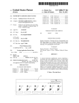
M-3269/00
ENVIRONMENTAL MONITORING AND CONTROL
] Metering & Control Instrumentation
] Refractometers
] Pumps & Tubing
] Air, Soil & Water Monitors
] Industrial Water & Wastewater Treatment
] pH, Conductivity & Dissolved Oxygen Instruments
HEATERS
] Heating Cable
] Cartridge & Strip Heaters
] Immersion & Band Heaters
] Flexibie Heaters
] Laboratory Heaters
DATA ACQUISITION
] Data Acquisition & Engineering Software
] Communications-Based Acquisition Systems
] Plug-in Cards for Apple, IBM & Compatibles
] Datalogging Systems
] Recorders, Printers & Plotters
pH/CONDUCTIVITY
] pH Electrodes, Testers & Accessories
] Benchtop/Laboratory Meters
] Controllers, Calibrators, Simulators & Pumps
] Industrial pH & Conductivity Equipment
FLOW/LEVEL
] Rotameters, Gas Mass Flowmeters & Flow Computers
] Air Velocity Indicators
] Turbine/Paddlewheel Systems
] Totalizers & Batch Controllers
http://www.omega.com
e-mail: [email protected]
Portable Infrared Thermometer
OSP 100 series
PRESSURE, STRAIN AND FORCE
] Transducers & Strain Gauges
] Load Cells & Pressure Gauges
] Displacement Transducers
] Instrumentation & Accessories
TEMPERATURE
] Thermocouple, RTD & Thermistor Probes, Connectors,
Panels & Assemblies
] Wire: Thermocouple, RTD & Thermistor
] Calibrators & Ice Point References
] Recorders, Controllers & Process Monitors
] Infrared Pyrometers
Where Do I Find Everything I Need for
Process Measurement and Control?
OMEGA…Of Course!
User’s Guide
WARRANTY/DISCLAIMER
OMEGA ENGINEERING, INC. warrants this unit to be free of defects in materials and workmanship for a period of 13
months from date of purchase. OMEGA’s Warranty adds an additional one (1) month grace period to the normal one (1)
year product warranty to cover handling and shipping time. This ensures that OMEGA's customers receive maximum
coverage on each product.
If the unit malfunctions, it must be returned to the factory for evaluation. OMEGA's Customer Service Department will
issue an Authorized Return (AR) number immediately upon phone or written request. Upon examination by OMEGA, if
the unit is found to be defective it will be repaired or replaced at no charge. OMEGA's WARRANTY does not apply to
defects resulting from any action of the purchaser, including but not limited to mishandling, improper interfacing,
operation outside of design limits, improper repair, or unauthorized modification. This WARRANTY is VOID if the unit
shows evidence of having been tampered with or shows evidence of being damaged as a result of excessive corrosion;
or current, heat, moisture or vibration; improper specification; misapplication; misuse or other operating conditions
outside of OMEGA's control. Components which wear are not warranted, including but not limited to contact points,
fuses, and triacs.
OMEGA is pleased to offer suggestions on the use of its various products, However, OMEGA neither assumes
responsibility for any omissions or errors nor assumes liability for any damages that result from the use of its
products in accordance with information provided by OMEGA, either verbal or written. OMEGA warrants only
that the parts manufactured by it will be as specified and free of defects. OMEGA MAKES NO OTHER
WARRANTIES OR REPRESENTATIONS OF ANY KIND WHATSOEVER, EXPRESSED OR IMPLIED, EXCEPT THAT
OF TITLE, AND ALL IMPLIED WARRANTlES INCLUDING ANY WARRANTY OF MERCHANTABILITY AND FITNESS
FOR A PARTlCULAR PURPOSE ARE HEREBY DISCLAIMED. LIMITATlON OF LIABILITY: The remedies of
purchaser set forth herein are exclusive and the total liability of OMEGA with respect to this order, whether
based on contract, warranty, negligence, indemnification, strict liability or otherwise, shall not exceed the
purchase price of the component upon which liability is based. In no event shall OMEGA be liable for
consequential, incidental or special damages.
CONDITIONS: Equipment sold by OMEGA is not intended to be used, nor shall it be used: (1) as a ”Basic Component”
under 10 CFR 21 (NRC), used in or with any nuclear installation or activity; or (2) in medical applications or used on
humans. Should any Product(s) be used in or with any nuclear installation or activity, medical application, used on
humans, or misused in any way, OMEGA assumes no responsibility as set forth in our basic WARRANTY/DISCLAIMER
language, and additionally, purchaser will indemnify OMEGA and hold OMEGA harmless from any liability or damage
whatsoever arising out of the use of the Product(s) in such a manner.
RETURN REQUESTS / INQUIRIES
Direct all warranty and repair requests/inquiries to the OMEGA Customer Service Department. BEFORE RETURNING ANY
PRODUCT(S) TO OMEGA, PURCHASER MUST OBTAIN AN AUTHORIZED RETURN (AR) NUMBER FROM OMEGA'S
CUSTOMER SERVICE DEPARTMENT (IN ORDER TO AVOID PROCESSING DELAYS). The assigned AR number should
then be marked on the outside of the return package and on any correspondence.
The purchaser is responsible for shipping charges, freight, insurance and proper packaging to prevent breakage in transit.
FOR WARRANTY RETURNS, please has the
following information available BEFORE
contacting OMEGA:
1. P.O. number under which the product was
PURCHASED,
2. Model and serial number of the product
under warranty, and
3. Repair instructions and/or specific problems relative to
the product.
FOR NON-WARRANTY REPAIRS, consult OMEGA for
current repair charges. Have the following information
available BEFORE contacting OMEGA:
1. P.O. number to cover the COST of the repair,
2. Model and serial number of product, and
3. Repair instructions and/or specific problems relative to
the product.
OMEGA's policy is to make running changes, not model changes, whenever an improvement is possible. This affords our customers the latest in
technology and engineering.
OMEGA is a registered trademark of OMEGA ENGINEERING, INC.
(C) Copyright 1999 OMEGA ENGINEERING, INC. All rights reserved. This document may not be copied, photocopied, reproduced, translated, or
reduced to any electronic medium or machine-readable form, in whole or in part, without prior written consent of OMEGA ENGINEERING, INC.
General
Operational Flow Chart
The OSP100 is the ideal tool for periodic process monitoring and for measuring
temperature quickly and easily, by contact with the target or from distance. An optional
laser pinpointing method simplifies the identification of the measuring surface area.
The OSP100 is the essential tool for the prevention of a variety of temperature related
equipment or process malfunctions. It can prevent serious damage to bearings, motors,
valves, electrical switches and distribution conductors, cooling or steam traps, thermal
insulation deterioration, hot spots, engine performances, extrusion heads, depleted
refrigeration system, etc.
The instrument is rugged, accurate and compact for fast and easy periodic process
monitoring, to control quality and/or supervise production phases of cooked and
refrigerated foods.
NORMAL MODE KEYPAD
When alkaline batteries are used, DO NOT connect power module to input jack.
CE certifications
This instrument conforms to the following standards:
EN 50081-1: 1992, Electromagnetic emissions
EN 50082-1: 1992, Electromagnetic susceptibility
Basic functions
Probe
Display external probe/infrared measurements
Lamp
Backlight ON/OFF
HAL
LAL
e
Hold
Hold measurements in lower display. Refresh hold.
Min/Max
2nd
OSP100 uses a
High Quality custom display
Circular switch between Average, Minimum or Maximum measurements on lower display.
Activate 2nd function keys.
2nd +
Laser beam mode: Continuous / Flashing (economy mode).
2nd + Probe =
°C/°F
Switch engineering temperature units.
2nd + Hold
=
HI
Set mode for HIGH alarm.
2nd +
=
LO
Set mode for LOW alarm.
Set e
Set mode for Emissivity.
Min/Max
2nd + Lamp =
SET MODE KEYPAD
Increase digit.
Probe
2nd
°C/°F
Decrease digit.
Lamp
Set
Store value and return in normal mode.
Hold
e
HI
Min/Max
LO
Set Alarm
Applications
FOOD (HACCP) To control and supervise production phases, handling, transport, and
conservation of cooked and refrigerated foods.
AUTOMOTIVE To check engine, bearings, muffler, brakes, etc.
INDUSTRIAL & ELECTRICAL Bearings, motors, valves, switches, insulation, etc.
HVAC/R Heating & cooling systems, thermal insulation, radiators, ducts, etc.
Optics
To take a temperature reading, point the unit at the target you wish to measure. Push and
keep the trigger pushed. The current temperature reading is displayed. Last reading before
previous switching-off is displayed in lower display. Release the trigger. A “Lock” symbol on
the LCD will be displayed and the Hold value is refreshed. OSP100 will remain switched on
for 40 seconds. The time will reset if a key is pressed or a serial communication message is
sent.. Press and release quickly the trigger to switch the instrument off.
The OSP100L and 100XL models can be supplied with a laser sighting with either a “laser
dot” to read the target area center or with a “laser circle” to read the target area. Press the
[*] key to enable/disable the laser. The message “LAS EN” or “LAS DIS” will be displayed.
When enabled, the laser can be switched on by pressing the trigger button for more than
1 sec. The laser will automatically switch off when the trigger button is released. The
emission indicator symbol (*) will appear on lower display.
Press in sequence the [2nd] and [*] keys to change the laser beam mode between
Continuous and Flashing (to increase battery expected life) mode.
Press the [Lamp] key to switch back-light on or off.
Press in sequence the [2nd] and [°C/°F] keys to change the engineering units between °C
and °F.
Distance: Sensor to Object (in)
9
0
20 25
80
40
120
9.4
Spot DIA* (in)
6.2
3
Spot DIA* (mm)
.9
23
25
4.0
1.4
1
.5
Enhanced functions
2.7
1.4
35
12
67
35
100
75
* Spot size measured
at 90% energy
0
225 500 625
OSP100XL
Nominal D:S = 30:1
157
238
1000
2000
OSP100, OSP100L
Nominal D:S = 12:1
3000
Distance: Sensor to Object (mm)
Warnings and Cautions
!
!
!
!
!
OSP100L and OSP100LX models only
USE OF CONTROLS OR ADJUSTMENTS OR PERFORMANCE OF
PROCEDURES OTHER THAN THOSE SPECIFIED HERE MAY RESULT IN
HAZARDOUS RADIATION EXPOSURE.
DO NOT LOOK AT THE LASER BEAM COMING OUT OF THE LENS OR VIEW
DIRECTLY WITH OPTICAL INSTRUMENTS - EYE DAMAGE CAN RESULT.
USE EXTREME CAUTION WHEN OPERATING THE LASER.
NEVER POINT THE LASER BEAM AT A PERSON.
KEEP OUT OF REACH OF ALL CHILDREN.
CAU T I O N
LASER RADIATION - DO NOT STARE INTO BEAM
MAX.OUTPUT<1mW, WAVELENGTH 630-670nm
CLASS I I LASER PRODUCT
COMPLIES WITH 21CFR CHAPTER 1, SUBCHAPTER J
AVOID EXPOSURE
LASER RADIATION
IS EMITTED FROM
THIS APERTURE
External probe operation. Connect the Pt100 resistance thermometer to the appropriate
connector. Switch the unit on and press the [Probe] key. The “EXT” message will be
displayed on the lower display for Pt100 readings.
Hold measurement. Press the [HOLD] key to freeze the displayed temperature. The hold
value will be displayed in lower display. On the main display the temperature is that actually
measured. Press the key again to refresh the Hold indication.
The Hold indication is refreshed by pressing the trigger for more than 1 sec with the unit in
measuring mode and releasing the trigger. Switch the OSP100 off by pointing the unit to
the target to recall the last value when you switch the unit on.
Select Average (AVG), Minimum (MIN) and Maximum (MAX) values. Press the [Min/Max]
key until the appropriate message is displayed. The unit will refresh the values of each
measurement from the power on. To reset the values, press the [2nd] key or switch the unit
off and on.
Emissivity adjustments. Press in sequence the [2nd] and [Set e] keys to change the emissivity
from 0.30 to 1.00 with 0.01 resolution. On the lower display the set value is shown. Press
the [UP] and [DOWN] keys to increase and decrease the emissivity. Press the [ENTER] key to
store and return on the normal mode measurement.
Set low (LAL) and high (HAL) alarms. Press in sequence the [2nd] and [HI] keys to change
the High alarm set point.. “HAL” will be seen on the display. The stored High alarm will be
displayed. The High alarm level is to be set by adjusting the [UP] or [DOWN] keys. Press the
[HI] key to enable/disable the acoustic alarm. Press the [ENTER] key to store the displayed
value and return to normal mode. Press in sequence the [2nd] and [LO] keys to change the
Low alarm set point..“LAL” will be seen on the display. The Low alarm level is to be set by
adjusting the [UP] or [DOWN] keys. Press the [LO] key to enable/disable the acoustic alarm.
Press the [ENTER] key to store the displayed value and return in normal operation mode.
When the measurement is inside the programmed alarm band, the “LAL” or “HAL” symbol
will be lit and an intermittent beep will be emitted.
°F
+ -
°C
Lock
Specifications
! Spectral band: 8-14 mm
! Display: 3 ½ digit custom backlighted LCD plus labels for max, min, emissivity, Hold, °C, °F,
low battery.
! Resolution: 0.1°C up to 199.9°C. 1°C otherwise.
! Response time: 500 ms
! Target pinpointing: sight dot or circular laser sighting (L and XL models only)
! Emissivity: adjustable from 0.30 to 1.00
! Auto Power Off: Automatic power Off if no key is pressed for more than 40 sec.
! Alarm: low and high alarm with visual and acoustic beeper
! Signal processing: °C/°F, average, hold, max, min (where applicable)
! Accuracy IR channel:
range from 23°C to f.s. : ±1% of reading or ±1°C whichever is greater
range from -32°C to 23°C : ±1.5°C
! RTD channel: Pt100 IEC751 a385 (probe excluded)
Input range: from -32°C to 520°C
Accuracy: ±0.3% of rdg or ±0.3°C whichever is greater
! Laser sight::
Wavelength: 650nm, Beam diameter: 3mm, Beam divergence: <0.5mrad;
Laser indicator: asterisk on display
! FDA Classification: Class II, Complies with 21CFR Chapter 1, Subchapt.er J
! Safety Classification: Class 2
! Power supply: alkaline or rechargeable battery
! Battery life: 60 h (back light & laser off)
! Ambient temperature: -10 to +45°C / 10-95% RH non condensing
! Storage temperature: -30°C to +60°C
! Dimensions and weight: 180x140x45 mm 380g nett
Set
Laser pointer enable/disable
LASER RADIATION DO NOT STARE
INTO BEAM OR VIEW DIRECTLY
WITH OPTICAL INSTRUMENTS.
MAX.OUTPUT<1mW, WAVELENGTH 630670nm, CLASS 2 LASER PRODUCT
CONFORMS TO IEC825-1:1993
WARNING
DO NOT ATTEMPT TO OPEN THE LASER SIGHT MODULE.
(THERE ARE NO USER SERVICEABLE PARTS IN THE MODULE).
PATENT NOTICE: U.S. PAT. B1 5,368,392; 5,524,984; 5,727,880; 5,465,838; 5,823,678; 5,823,679.
Other U.S. and Foreign Patents and Applications Pending. Manufactured in Italy. Licensed by Omega
Engineering, Inc.