1
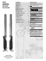
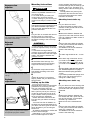
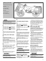
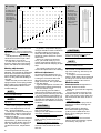
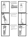
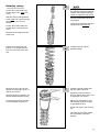
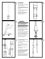
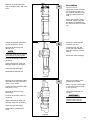
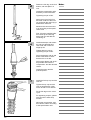
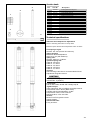
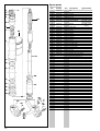
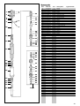
Owners manual
Öhlins motocross front forks FG 9910 Cannondale
Including:
Setting up
your bike
Fine-tuning
Service
the fork
Trouble
shooting
Technical
info
Spare parts
& tools
Traction, handling,
comfort and safety
1
Öhlins
motocross
front forks
FG 9910
Cannondale
Contents
Safety signals
Safety signals ................................. 2
Introduction .................................... 3
Design ............................................ 3
Before you start ............................. 3
Kit content ...................................... 3
Marking .......................................... 4
Recommended settings ................. 4
Mounting instructions ..................... 4
Setting up the bike ......................... 4
Checking front sag ......................... 4
Checking rear sag .......................... 5
Checking front ride height .............. 5
Checking rear ride height ............... 5
Fine-tuning the bike ....................... 5
Making adjustments ....................... 6
Oil level adjustment ....................... 6
Maintenance .................................. 6
Trouble shooting ............................ 7
Preload adjustment ........................ 8
Changing springs ........................... 9
Dismantling the front fork ............. 10
Assembly of the front fork ............. 11
Service tools ................................ 13
Technical specifications ............... 13
Spare parts .................................. 14
Important information concerning
safety is distinguished in this manual
by the following notations
The Safety alert symbol means:
Caution! Your safety is involved.
WARNING!
Failure to follow warning instructions
could result in severe or fatal injury to
anyone working with, inspecting or
using the suspension, or to bystanders.
CAUTION!
Caution indicates that special precautions must be taken to avoid
damage to the suspension.
NOTE!
This indicates information that is of
importance with regard to procedures
Kit contents
Before installing the front fork, please
check the contents of the kit, listed in
the mounting instruction. If anything is
missing, contact your Öhlins dealer.
NOTE!
During storage and transportation,
especially at high ambient temperature, the oil and grease used for assembling may run out inside the
packing and damage the expanded
polystyrene packing material. This is
not unusual and is in no way detrimental to the shock absorber.
© Öhlins Racing AB.
All rights reserved.
Any reprinting or unauthorised use
without the written permission of
Öhlins Racing AB is prohibited.
Printed in Sweden.
2
Introduction
Öhlins Racing congratulates you on
your choice of front fork for your
motocross bike.
All Öhlins products are designed
with just one aim; to win races. To
design a winner you need a concept
starting with a unique know-how. You
add engineering skill, precision and
the best material available. The result is quality, endurance and winning performance.
Your new Öhlins front fork is developed from experience gained during
years of successful cooperation with
the World Championship winning
works motocross teams.
Spring rates and damping forces
are developed just for your bike. The
design and the settings are consequently the results of extensive testing and no guesswork!
Öhlins shock absorbers and front
forks have dominated the motorcycle
scene for several years and have
captured more World Championship
titles than any other brand, over 60
titles!
A well equipped network of authorised Öhlins service centres around
the world, with specially trained mechanics, can help you with personally
tuned settings, service, repairs and
spare parts.
Design
Öhlins new up-side-down (USD) front
fork is designed to combine the
advantages of comfortable, safe
conventional forks and rigid, light
USD forks. The result is a unique
combination of being rigid, precise in
corners and during hard braking yet
comfortable, forgiving when “overlanding“ and in big bumps.
Your new Öhlins USD front fork
has aluminium outer legs and 46 mm
steel inner legs, with a polished titanium nitride surface for lowest possible friction.
The legs also feature a completely
new bushing design with two fixed
and one sliding bushing.
The new USD fork features the
Öhlins championship winning cartridge damping system.
The fork is fully adjustable with external adjuster for compression- and
rebound damping.
The compression adjuster is located
at the bottom of the fork leg, fig 1, the
rebound adjuster at the top, fig 2.
Spring preload is adjusted with
washers, fig 3, and optional springs
are available to suit different tracks
and riders.
In the legs there are also “airsprings“ (the air trapped above the
oil) that work together with the “real“
spring. You adjust the air-spring by
raising or lowering the oil level in the
legs.
By using different combinations of
springs and air-springs you can alter
the characteristic of the fork. For
example, a soft spring in combination
with a small air-spring (high oil level)
makes the fork progressive, see
“Fine-tuning the bike“.
Before you start
WARNING!
Installing a front fork, that is not approved by the vehicle manufacturer,
may affect the stability of your vehicle. Öhlins Racing AB cannot be held
responsible for any personal injury or
damage whatsoever that may occur
after fitting the front fork. Contact an
Öhlins dealer or other qualified
person for advice.
Marking
All Öhlins front forks are marked.
You will find the part number on the
inside of the fork bottom.
Your Öhlins front fork has the following marking:
FG 9910 Cannondale
Recommended settings
The front fork in your kit is adjusted
to the Öhlins recommended setting
for your bike, see “Making adjustments“. We advise you to use this as
your start setting.
Öhlins Racing AB can not be held
responsible for any damage whatsoever to front fork or vehicle, or injury
to persons, if the instructions for
fitting and maintenance are not
followed exactly. Similarly, the
warranty will become null and void if
the instructions are not adhered to.
WARNING!
Please study and make certain that
you fully understand all the mounting
instructions and the owner´s manuals before handling this front fork kit.
If you have any questions regarding
proper installation procedures, contact an Öhlins dealer or other qualified person.
WARNING!
The vehicle service manual must be
referred to when installing the Öhlins
front fork.
3
Compression
adjuster
Mounting instructions
WARNING
1. It is advisable to have an Öhlins
dealer or a qualified mechanic to fit
your front fork kit.
2. To install the kit you need your
motorcycle’s work shop manual.
3. When working on your motorcycle,
support it securely so it does not fall
over.
1.
The compression adjuster is located at
the bottom of the fork leg.
A
B
Put your bike on a stand and remove
the front wheel, the front brake
components and the fork legs from
the bike according to the work shop
manual.
Measure the distance between the
upper fork crown and the front wheel
axle, fig 4 distance A. Make a note of
the measurement.
CAUTION!
B
Fit the Öhlins front fork legs. For
recommended front fork mounting
height see mounting instruction.
C
3.
Spring preload is adjusted with washers
and optional springs are available.
4
A
Put your bike on a stand.
Arrange the stand so that the front
wheel is off the ground and the front
fork fully extended.
1. The outer legs, both left and right,
should be adjusted evenly in the fork
crown.
2. The Öhlins fork legs feature
grooves on top of the outer fork legs
to make adjustment of the fork height
easier. The distance between the
grooves is 4 mm.
Preload
adjustment
Checking front static sag
The Öhlins front fork is designed to fit
your bike’s standard triple clamps
and to use the standard brake components and wheel.
Rebound
adjuster
2.
The rebound adjuster at the top of the
fork leg.
ences, between the Öhlins recommended settings and the settings you
achieve, may occur. Therefore, it is
always wise to start the setting up by
checking!
The sag effects not just only the
suspension but also the rake of the
front fork and therefore the overall
behaviour of the bike
Fit the brake components and the
front wheel according to the work
shop manual.
D
Tighten all screws. For maximum
torque, please see your bike’s work
shop manual.
C
Remove the stand. With the wheels
on the ground measure the distance
again, fig 4 distance B.
The difference of the two measurements is the static sag.
D
The static sag should be 30 ± 10 mm.
E
If the static sag is less than 20 mm,
you need to reduce spring preload.
If the static sag is more than 40 mm,
you need to increase spring preload.
F
Spring preload is adjusted with spacers,
see “Preload adjustment“ on page 8.
Maximum allowed spring preload is
13 mm.
If you need to preload the springs more
than 13 mm, we recommend you to
change to a “stiffer“ spring.
Checking rear static sag
Setting up the bike
A
We would like to give you some basic
guidelines how to set up your bike
with your new Öhlins front fork.
However, remember that the front
fork is just one part of your motorcycle and to get the fork to work properly the whole motorcycle has to be
set up according to standards.
Please follow the instructions below, see also your bike’s work shop
manual.
Your new front fork is dialled-in to
the Öhlins recommended settings for
your bike. The same goes for the rear
shock absorber if you are using an
Öhlins unit.
All settings are based on a bike and
a rider of normal weight.
Depending on your own and your
bike’s actual weight minor differ-
Put your bike on a stand. Arrange the
stand so that the rear wheel is off the
ground and the rear suspension fully
extended.
B
Measure the distance between the
rear wheel axle and a point near the
rear end of the seat, for example a
seat bolt, fig 4 distance A.
Make a note of the measurement.
C
Remove the stand. With the wheels
on the ground measure the distance
again, fig 4 distance B.
The difference of the two measurements is the static sag.
Setting up the bike
NOTE!
D
Refer to mounting instruction for
more specific set-up data
If you need to change the springs,
see “Changing springs“ on page 9.
D
E
The static sag should be 30 ±10 mm.
Stiffer springs are needed if the
difference is more than 60 mm.
Softer springs if the difference is less
than 40 mm.
Consult your Öhlins dealer for the
right rate.
E
If the static sag is less than 20 mm,
you need to reduce spring preload.
If the static sag is more than 40 mm,
you need to increase spring preload.
C: Rider on.
A: Fully extended.
n.
er o
Rid
Rear ride height:
A - C = 100 ± 10 mm.
B: On the ground.
und
gro
C:
On
Ful
B:
A:
Rear sag:
A - B = 30 ±10 mm.
ly e
Front ride height:
A - C = 50 ± 10 mm.
the
xte
nde
Front sag:
A - B = 30 ± 10 mm.
.
d.
4.
Checking sag and ride height.
Should you still experience excessive bottoming or that the bike feels
much to stiff and suspension travel is
not fully used, harder/softer than normal springs may be needed for the
track you are testing on.
Consult your Öhlins dealer for advice!
Fine-tuning the bike
Race dressed sit on the bike, straight
above the foot pegs, with the feet
barely touching the ground. Have
somebody to measure between the
same point as before, fig 4 distance C.
Learning how to use the adjusters will
take time but you quickly appreciate
them once you know the tricks. Even
the specialists sometimes need a
specialist!
With the adjusters you optimize the
suspension for your, riding style and
the track you are competing on.
The same basic guide lines go for
both the front fork and the rear shock
absorber.
Too much compression damping
will give you a harsh ride as your bike
“jumps“ along the track.
With too much rebound damping
your bike will have difficulties with
several bumps in a row. The suspension will not extend fast enough between bumps, your bike will ride
lower and lower and eventually the
suspension will bottom!
Race dressed sit on the bike, straight
above the foot pegs, with the feet
barely touching the ground.
Have somebody to measure between
the same point as before, fig 4 distance C.
C
External adjusters
The difference of the two measurements should be 100 ± 10 mm.
C
Do not try to alter ride height by altering the spring preload.
A new spring is needed.
On the Öhlins front fork the adjusters
are bleed valves, totally separated
from each other.
The compression bleed valve controls the flow in the cartridge tube
during the compression stroke, the
rebound bleed valve the flow during
the rebound stroke.
F
Checking rear ride height
A
Adjust the spring preload according
to your rear shock mounting instruction.
Checking front ride height
A
Put your bike on a stand.
Arrange the stand so that the front
wheel is off the ground and the front
fork fully extended.
Measure the distance between the
upper fork crown and the front wheel
axle, fig 4 distance A. Make a note of
the measurement.
B
The difference of the two measurements should be 50 ± 10 mm.
CAUTION!
Do not try to alter ride height by altering the spring preload.
New springs are needed.
Put your bike on a stand. Arrange the
stand so that the rear wheel is off the
ground and the rear suspension fully
extended.
Measure the distance between the
rear wheel axle and a point near the
rear end of the seat, for example a
seat bolt, fig 4 distance A.
Make a note of the measurement.
B
CAUTION!
D
A stiffer spring is needed if the
difference is more than 110 mm.
A softer spring if the difference is less
than 90 mm.
Consult your Öhlins dealer for a spring
of the right rate.
CAUTION!
Using too much force when closing
the adjusters will destroy important
sealing surfaces.
5
Oil level 110 mm
Oil level 120 mm
Oil level 130 mm
Oil level
6.
Oil level is
measured from
the top of the
outer leg, with
the top nut of,
the fork fully
compressed
and no preload
washer nor
spring installed.
500
450
400
F 350
o
r 300
c
e 250
Force
5.
A change in oil
level will effect
the damping
forces, not in the
early stage of
fork travel but a
great deal in the
later stage.
Oil level 100 mm
Oil level
Air spring
k 200
g
f 150
100
50
0
0
20
40
60
Stroke
80
100
120
Stroke mm
Both the adjusters have a normal
right-hand thread.
Click position zero (0) is when the
adjusters are turned clockwise to fully
closed.
The adjustment range, from fully
closed until maximum open valve
(anticlockwise), is 20 clicks.
In order not to click in the wrong
direction; always first close the adjuster, then dial-in the new setting.
Making adjustments
To make improvements using the
adjusters, it is important to understand
the function of the front fork and the
shock absorber and through testing
learn how they effect the handling of
your bike.
Make sure that you have the correct
springs and the correct spring preload
before making any adjustments. And
always start with the Öhlins recommended settings:
NOTE!
See mounting instruction for
recommended settings.
NOTE!
Higher click numbers give less damping force.
When making adjustments; keep
notes, make adjustments one at a
time... and in small steps.
The adjusters should normally not
be adjusted in steps of more than 2
clicks at a time and not outside the
usable click range.
When you think you have made an
improvement, go back to what you
started with and double check to be
sure. Pay attention to changes in
conditions like tires, temperatures
etc.
6
In general, compression damping
changes should be used to influence
the bike’s stability and response,
while rebound damping changes
should be used to influence comfort
and traction.
When you need more damping
force, you should mainly try to increase compression damping and
use as little rebound damping as possible.
This usually means that you gain
comfort and performance in handling.
Oil level adjustment
As the air trapped between the oil
and the top nut acts as an air-spring,
a change in oil level will effect the
damping forces. Not in the early
stage of fork travel, but a great deal
in the later stage.
A general description of how the oil
level/air-spring effects the damping
forces are shown in fig 5.
The air-spring gives the Öhlins
USD fork a progressive spring rate,
preventing it from bottoming out hard.
By using different combinations of
springs and oil levels/air-springs you
can alter the characteristic of the fork
and tailor it to suit different tracks and
conditions.
CAUTION!
The oil level must be the same in
both front fork legs.
Riding a bike with different oil levels
will cause instability.
When the oil level is raised:
The air-spring in the later half of
travel is strong, and thus the front
fork hard.
When the oil level is lowered:
The air-spring in the later half stage
of travel is soft, and thus the front
fork soft.
CAUTION!
Adjust the oil level with the fork leg
fully compressed and no preload
washer nor spring installed.
NOTE!
See mounting instruction for
recommended oil level.
The oil level is measured from the
top of the outer leg, with the top nut
off, see fig 6.
A change in oil level should be
made in small steps. We recommend
a change of 5 mm at a time and not
outside the range of 80-130 mm.
Maintenance
Telescopic front forks depend on a
smooth, friction free action.
Make sure your forks are regularly
serviced.
Do not use strong solvents, such
as brake cleaner, to clean the front
forks. This will dry out the seals and
the steel tubes and cause friction or
leakage.
After every race:
Clean externally and spray with an
all-purpose oil after washing with
detergent.
Check externally for damage.
Put a little Öhlins green grease
(148-01) on the steel tubes and
work it in by pushing the fork up
and down.
Every 20 hours:
Dismantle the fork and check all
parts for wear and damage, replace
if necessary, see page 10.
General handling set-up
A
handle smaller bumps.
Damping force not progressive
enough.
✓ Increase the oil level.
soft during the entire wheel travel.
Spring too soft, compression damping too low.
✓ Increase the compression
damping.
✓ Change to harder spring.
Front end falls into the curves
(over-steering) especially in sand.
Steep front fork angle. Front end too
low in comparison to rear end.
✓ Increase the front fork
compression damping.
✓ Change to harder springs.
✓ Lower fork leg approximately
5 mm in the triple clamp.
Can handle smaller bumps but is
too hard during the last part of the
travel.
Damping force is too progressive.
✓ Decrease the oil level.
B
E
Front end ”ploughs”, understeers.
Shallow front fork angle. Front end
too high in comparison to rear end.
✓ Decrease the front fork
compression damping.
✓ Raise the fork legs approximately
5 mm in the triple clamp.
✓ Change to softer fork springs.
Front end feels low, initially feels
soft, but is not bottoming.
The initial spring rate is too soft or
spring preload is too low.
✓ Increase the spring preload.
Suspension is bottoming, feels
harsh and sags down too much
with the rider in the saddle.
Spring too soft or compression
damping too low.
✓ Increase the spring preload,
check ride height. 95 +- 5 mm.
✓ Change to harder spring if the
load is more than 100 mm.
✓ Increase compression damping.
E
D
Front end unstable at high speed,
unstable when accelerating out of
curves.
Front fork angle too steep. Front end
too low in comparison to rear end.
✓ Lower the fork legs approximately 5 mm in triple clamp.
✓ Change the front fork springs to
harder ones.
Feels harsh over small bumps, but
using full wheel travel.
Too much spring preload or too much
compression damping.
✓ Increase the oil level or change
to softer springs.
✓ Decrease the compression
damping.
✓ Decrease the spring preload.
✓ Clean the oil seals and scrapers.
Use Öhlins grease 148-01 for
regreasing.
D
F
Rear wheel jumps over small
bumps during deceleration or
when going downhill. Traction not
satisfactory in washboard curves.
Too much spring preload, as the
spring is probably too soft, will cause
the spring to extend too fast.
✓ Change to a harder spring in
order to achieve a balanced
position using less spring preload.
✓ Check the static sag and
ride height.
Front end unstable during deceleration.
Front fork angle too steep during
braking. Front end too low or rear
end too high.
✓ Increase the oil level in the
front fork.
✓ Change to harder fork springs.
✓ Increase the front fork
compression damping.
Can handle the first in a series of
bumps but feels hard after a few
more bumps. Frontal grip insufficient in rough and bumpy turns.
Too much rebound damping.
✓ Decrease the rebound damping.
C
Front suspension.
A
Front fork travel is not used to its
full capacity. Harsh feeling, front
wheel grip is not satisfactory in
bumpy turns.
Suspension too hard.
✓ Decrease the front fork
compression damping.
✓ Change to softer springs.
B
Suspension bottoming, too soft
during entire travel.
Spring too weak or compression
damping too soft.
✓ Increase oil level 5 mm.
✓ Increase compression damping.
✓ Change to stiffer springs.
C
Suspension bottoming, but can
D
G
Front end rebound too fast after a
bump. Front wheel grip insufficient
in bumpy curves.
Not enough rebound damping, or too
much spring preload
✓ Increase the rebound damping.
✓ Decrease the spring preload.
Rear suspension.
A
Rear suspension stroke is not
used to its capacity. Suspension
feels harsh. Traction not satisfactory in bumpy curves.
Suspension hard in general or too
much compression damping, too
much spring pre-load.
✓ Decrease the compression
damping.
✓ Decrease the spring preload.
✓ Change to softer spring.
C
E
Rear end kicks up over bumps
with sharp edges, but can handle
bumps with round edges.
Compression damping too hard.
✓ Decrease the compression
damping.
F
Rear end becomes too low in
series of bumps. Traction not
satisfactory in washboard type
curves or when decelerating on
washboard ground.
Rebound damping too slow.
✓ Decrease the rebound damping.
G
Rear end very unstable. Shock
does not respond to adjustments.
Shock damping is gone, caused of
low gas pressure, bad oil is used, or
components are broken in the shock
absorber. Service is needed.
✓ Gas filling required.
✓ Change shock oil.
✓ Repair or change the shock
absorber.
B
Suspension is bottoming, feels
7
a
Preload adjustment
a
Put the bike on a stand and
loosen the screws in the fork
top crown that hold the fork
legs.
NOTE
On most MX-bikes you have to
take of the handle bar before
you can unscrew the top cap.
Unscrew the top cap, use a 24
mm wrench.
b
Put a box under the front wheel
so that the springs are visible.
b
Loosen the top cap from
damper rod extender and remove it.
Remove the spring support.
c
Install a new preload spacer to
achieve the right static sag.
Fit the spring support, top cap
and the handle bar.
Tighten all screws.
For tightening torques, please
see your bike's work shop
manual.
8
c
Changing springs
d
NOTE
Closing the compression- and
the rebound valves will keep the
damper rod extended making it
easier to install the new spring.
Loosen the screws that hold
the fork legs in the upper fork
crown.
With the fork leg still tightened
in the lower fork crown unscrew
the top cap, use a 24 mm
wrench.
Pull out the damper rod as far
as possible.
Close the compression and the
rebound valve (clockwise).
Loosen the screws that hold
the fork legs in the lower fork
crown.
Remove the fork legs from the
motorcycle.
Fasten the fork leg with soft
jaws in a vice and loosen the
lock nut on the top of the fork
cap.
Remove the top cap from the
damper rod extender, use a 16
and 24 mm wrench.
Remove the spring support, the
preload washer and the spring.
For free spring length see technical information on page 13.
e
Install the spring and the
preload washer.
f
Install the spring support fork
top cap and the lock nut.
Tighten the top cap and the
lock nut against each other, use
a 16 and 24 mm wrench.
Adjust the compression- and
the rebound valves according
to specification card.
Fit the fork legs on the motorcycle.
For tightening torques, please
see your bike's work shop
manual.
9
a
Dismantling
d
Perform steps a-d "Changing
springs" on page 9.
Loosen the bush head, on top
of the cartridge tube, with tool
1797-01.
Lift up the damper rod assembly and drain the oil.
Pull up the scraper with a
screwdriver, release and remove the circlip.
1797-01
b
CAUTION!
e
The fork legs have three fixed
and one sliding bushing.
Be very careful when disassembling the fork legs.
Fasten the fork leg horizontally with soft jaws in a vice.
Use a hot air gun to warm up
the outer leg where the bushings are located.
្
15o mm
The first bushing is located at
the bottom end of the outer
leg, the second approximately
150 mm further up the leg.
៑
Between them is a sleeve to
maintain the distance.
c
Use the special tool 1702-02 to
remove the bushings.
Install the tool in the top of the
inner steel leg.
1702-02
Screw the top cap onto the
tool and install the cap in the
outer leg.
Rotate the tool to press out
the bushings.
If tool 1702-02 not is avaliable
push the inner steel leg to the
bottom and then pull it back
quickly, so that the fork is
topping out hard.
Repeat this procedure until the
seal and the bushings can be
pulled out from the outer leg.
10
f
Remove the seals and bushings and replace them with new
ones.
a
Assembling
Apply a thin layer of Öhlins
green grease (148-01) on
the scraper ring and on the
sealing surface of the fork
seal.
Mount the scraper, circlip,
fork seal, support ring and
the bushings separated by
the sleeve on the inner steel
leg.
Fasten the damper rod assembly with soft jaws in a vice.
b
Fasten the outer leg with
soft jaws in a vice.
Install the inner leg and
mount the upper bushing
with tool 1799-02, and the
sleeve.
Remove all parts from the
damper rod.
NOTE
If the right order is lost, use the
specification card as a guide.
Mount the lower bushings.
Put them in the right order on
the bench.
Inspect all parts for wear and
damage, replace if necessary.
Clean all parts thoroughly.
Assemble the damper rod.
1799-02
Remove the compression valve
assembly from the fork bottom,
use a 17 mm socket.
c
Apply some Öhlins green
grease on the seals.
Fasten the valve assembly with
soft jaws in a vice.
Again, use tool 1799-02 turn
it around to install the seal
in the outer leg.
Remove all parts from the
valve body.
Install the circlip and the
scraper.
CAUTION!
Put them in the right order on
the bench.
Make sure the circlip is
fitted correctly into the
groove in the outer leg.
Inspect all parts for wear and
damage, replace if necessary.
Clean all parts thoroughly.
Assemble the compression
valve.
1799-02
11
d
Fasten the fork leg, at the fork
bottom, with soft jaws in a
vice.
Install the compression valve
assembly in the fork bottom.
Tightening torque 45 Nm.
Apply some front fork oil on
the outer surface of the inner
leg, and push the outer leg up
and down a few times.
Measure the correct amount
of oil according to the specification card.
First, fill up the cartridge tube,
then raise up the outer leg
about 250 mm and add the
remaining oil.
e
Install the damper rod assembly into the cartridge tube.
Use Lotite 542 on the cartridge top lid.
Tighten with tool 1797-01.
Tightening torque 40 Nm.
Pump the damper rod up and
down a few times to check
that there is no air left.
Pull out the damper rod as far
as possible and close the
compression- and the rebound
valves.
Install the spring and the
preload spacer.
f
Install the fork top cap and the
lock nut.
Tighten the top cap and the
lock nut against each other,
use a 16 and 24 mm wrench.
Fit the fork legs on the motorcycle.
For tightening torques, please
see your bike's work shop
manual.
Adjust the compression- and
the rebound valves according
to the specification card.
12
Notes
Service tools
3
2
1
Pos.
Part No.
1
2
3
4
5
1799-02
0786-03
1797-01
0787-03
1702-02
Description
Bushing/seal mounting tool
Inner tube tool
Tool-cylinder tube lid
Cylinder tube tool (cartridge)
Bushing remover tool
4
5
Technical specifications
Rebound and compression adjustment
Refer to mounting instruction for set-up data.
Maximum open rebound and compression valve: 20 clicks.
Free Spring Length:
All forks: 467 mm (service limit 460 mm).
Spring preload:
Maximum allowed adjustment
range 3-13 mm (with washers).
Spring rate:
All forks: 2328-45: 4,5 N/mm.
Optional spring rate:
2328-39: 3,9 N/mm.
2328-41: 4,1 N/mm
2328-43: 4,3 N/mm
2328-45: 4,5 N/mm.
2328-47: 4,7 N/mm
Oil level:
See mounting instruction for recommended oil level.
Adjustment range 90-130 mm.
CAUTION!
Use only Öhlins high performance front
fork fluid No. 5 (1305-01).
Loctite glue:
542 for fork bottom thread and cartridge top lid.
Tighten torque:
Triple clamp bolt: See your bike's work shop manual.
Compression valve: 45 Nm (Base valve).
Cylinder tube lid (cartridgetube): 40 Nm
Compression valve, 8 mm nut 8 Nm.
Rebound valve, 8 mm nut 8 Nm.
Grease:
Öhlins Front Fork grease 148-01
(Green grease).
Service Intervals:
Every 20 hours.
13
Spare parts
2
3
1
4
5
28
Pos.
Part No.
Pcs.
Description
1
2
3
4
5
6
7
02338-01
01050-01
00338-59
02306-02
00438-17
02337-01
02319-01
2
2
2
2
2
2
Nut
Screw
O-ring
End cap
O-ring
Spring support
Spring washer
8
02328-39
2
Spring
9
10
11
12
13
14
15
16
17
18
19
20
21
22
23
24
25
26
27
28
02324-02
02332-03
00329-02
02021-01
02325-01
02021-01
01552-01
02336-01
02015-01
02014-01
02339-01
02022-01
02315-83
02314-01
00438-30
02333-01
02333-02
02314-02
2
2
2
2
2
2
2
2
2
2
2
2
2
2
2
1
1
4
1
1
Outer tube
Sticker
Circlip
Bush
Sleeve
Bush
Washer
Seal
Circlip
Scraper
Cylinder tube
Bush
Fork leg inner
Screw
O-ring
Bottom piece CN, left
Bottom piece CN, right
Screw
See next page Fig. A
See next page sep. drawing
6
7
8
10
9
19
11
12
13
20
14
15
21
16
17
18
23
22
25
24
26
26
27
14
Type/remarks
see spec. card
Spring preload
see spec. card
Spring
Spare parts
1
2
3
24
4
5
6
25
26
27
28
9
7
10
8
}
29
30
31
11
32
33
34
12
36
37
38
13
39
40
41
43
42
14
15
16
17
44
45
46
18
47
}
Pos.
Part No.
Pcs.
5
6
7
8
9
10
11
12
13
14
15
16
17
18
19
20
21
22
23
24
25
26
27
28
29
30
31
32
33
34
36
37
38
39
40
41
42
43
44
45
46
47
48
49
50
51
52
53
01473-02
00338-53
02321-02
01248-01
00884-04
02366-12
00338-76
02301-03
02302-03
02303-01
02304-01
00131-05
01499-01
02305-03
02059-01
00338-19
00110-01
02340-01
02307-01
02063-02
00438-31
02356-03
02322-01
02320-03
2
2
2
2
4
2
2
2
2
2
2
2
2
2
2
2
2
2
2
2
2
2
2
2
01149-01
00530-22
02335-01
01447-02
2
2
2
2
00153-01
00430-05
01473-02
00338-53
01242-05
01248-01
00884-04
02054-02
00438-02
2
2
2
2
2
2
2
4
2
2
2
02334-01
00438-03
00530-21
01149-01
00153-01
00430-05
2
2
2
2
2
2
Description
Type/remarks
Circlip
O-ring
Adjustment screw
Spring
Ball
Adjustment rod
O-ring
Needle housing
Guide sleeve
Sleeve
Hydraulic stop
Circlip
Circlip
Cylinder tube cap
Bushing holder
O-ring
Bush
Washer
Shaft
Spring
O-ring
Rebound needle
Spring
Piston holder
Shims
see spec. card
Wave washer
see spec. card
Shims
Rebound piston
Piston ring
Shims
see spec. card, rebound
Clamp washersee spec. card, rebound
Washer
Nut
Circlip
O-ring
Adjustment needle
Spring
Ball
End piece
O-ring
Clamp washer
see spec. card
Shims
see spec. card
Compression piston
O-ring
Shims
Wave washer
Washer
Nut
48
49
50
51
52
53
19
20
21
22
23
Fig A
15
Öhlins Racing AB, Box 722, S-194 27 Upplands Väsby, Sweden.
Phone +46 8 590 025 00, fax +46 8 590 025 80.
E-mail: [email protected]
16
Cannondale Teknisk Illustration AB, OM motocross front fork, 99 12, 400 ex.
Traction, handling,
comfort and safety