1
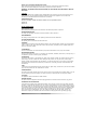
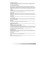
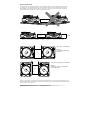
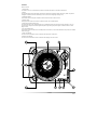
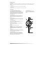
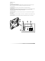
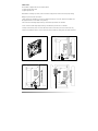
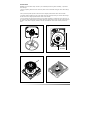
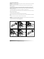
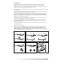
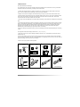
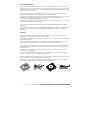
OPERATING INSTRUCTIONS
CONTENTS
CAUTION!
TO PREVENT THE RISK OF ELECTRIC SHOCK, DO NOT REMOVE COVER (OR
BACK). NO USER-SERVICEABLE PARTS INSIDE. REFER SERVICING TO
QUALIFIED SERVICE PERSONNEL.
Safety Precautions
1
Setup & Installation
3
Controls
4
Cable Setup
7
Platter Setup
8
Interchanging Tonearm Tubes
IMPORTANT
The lightning flash with arrowhead symbol, within an equilateral triangle, is
intended to alert the user to the presence of un-insulated "dangerous voltage"
within the product's enclosure that may be of sufficient magnitude to constitute
a risk of electric shock to persons.
NOTICE
The exclamation point within an equilateral triangle is intended to alert the user
to the presence of important operating and maintenance (servicing)
instructions in the literature accompanying the appliance.
NOTICE
The apparatus shall not be exposed to dripping or splashing and that no objects
filled with liquids, such as vases, shall be placed on the apparatus.
9
Tone Arm Setup
10
Cartridge Setup
11
Important Notes & Operation
12
Specifications
13
Trouble Shooting
14
Thank you for purchasing this Numark product.
Please read these operating instructions so you will know how to operate this equipment properly.
After you have finished reading these instructions, keep them for future reference.
WARNING: TO PREVENT FIRE OR SHOCK HAZARD, DO NOT EXPOSE THIS APPLIANCE TO RAIN OR
MOISTURE.
CAUTION:
This product satisfies FCC regulations when shielded cables and connectors are used to connect the unit to
other equipment. To prevent electromagnetic interference with electric appliances such as radios and
televisions, use shielded cables and connectors for connections.
IMPORTANT NOTICE:
RECORD THE MODEL NUMBER AND SERIAL NUMBER OF THIS EQUIPMENT BELOW.
MODEL NO:
SERIAL NO:
SAFETY PRECAUTIONS
READ INSTRUCTIONS
All the safety and operating instructions should be read before the product is operated.
RETAIN INSTRUCTIONS
The safety and operating instructions should be retained for future reference.
HEED WARNINGS
All warnings on the product and in the operating instructions should be adhered to.
FOLLOW INSTRUCTIONS
All operating and use instructions should be followed.
CLEANING
Unplug this product from the wall outlet before cleaning. The product should be cleaned only with a polishing
cloth or a soft dry cloth. Never clean with furniture wax, benzene, insecticides or other volatile liquids since
they may corrode the cabinet.
ATTACHMENTS
Do not use attachments not recommended by the product manufacturer as they may cause hazards.
WATER AND MOISTURE
Do not use this product near water - for example, near a bathtub, washbowl, kitchen sink, or laundry tub; in a
wet basement; or near a swimming pool; and the like.
ACCESSORIES
Do not place this product on an unstable cart, stand, tripod, bracket, or table. The product may fall, causing
serious injury to a child or adult and serious damage to the product. Use only with a cart, stand, tripod,
bracket, or table recommended by the manufacturer, or sold with the product. Any mounting of the product
should follow the manufacturer's instructions, and should use a mounting accessory recommended by the
manufacturer.
CART
A product and cart combination should be moved with care. Quick stops, excessive force, and uneven surfaces
may cause the product and cart combination to overturn.
POWER SOURCES
This product should be operated only from the type of power source indicated on the marking label. If you are
not sure of the type of power supply to your home, consult your product dealer or local power company.
LOCATION
The appliance should be installed in a stable location.
NONUSE PERIODS
The power cord of the appliance should be unplugged from the outlet when left unused for a long period.
GROUNDING OR POLARIZATION
If this product is equipped with a polarized alternating current line plug (a plug having one blade wider than
the other), it will fit into the outlet only one way. This is a safety feature. If you are unable to insert the plug
fully into the outlet, try reversing the plug. If the plug should still fail to fit, contact your electrician to replace
your obsolete outlet. Do not defeat the safety purpose of the polarized plug. If this product is equipped with a
three-wire grounding type plug, a plug having a third (grounding) pin, it will only fit into a grounding type
power outlet. This is a safety feature. If you are unable to insert the plug into the outlet, contact your
electrician to replace your obsolete outlet. Do not defeat the safety purpose of the grounding type plug.
PAGE 1
SAFETY PRECAUTIONS
POWER-CORD PROTECTION
Power-supply cords should be routed so that they are not likely to be walked on or pinched by items placed
upon or against them, paying particular attention to cords at plugs, convenience receptacles, and the point
where they exit from the product.
OUTDOORS ANTENNA GROUNDING
If an outside antenna or cable system is connected to the product, be sure the antenna or cable system is
grounded to provide some protection against voltage surges and built-up static charges. Article 810 of the
National Electrical Code, ANSI/NFPA 70, provides information with regard to proper grounding of the mast and
supporting structure, grounding of the lead-in wire to an antenna discharge unit, size of grounding conductors,
location of antenna-discharge unit, connection to grounding electrodes, and requirements for the grounding
electrode.
LIGHTNING
For added protection for this product during a lightning storm, or when it is left unattended and unused for
long periods, unplug it from the wall outlet and disconnect the antenna or cable system. This will prevent
damage to the product due to lightning and power-line surges.
POWER LINES
An outside antenna system should not be located in the vicinity of overhead power lines or other electric light
or power circuits, or where it can fall into such power lines or circuits. When installing an outside antenna
system, extreme care should be taken to keep from touching such power lines or circuits, as contact with them
might be fatal.
OVERLOADING
Do not overload wall outlets, extension cords, or integral convenience receptacles as this can result in a risk of
fire or electric shock.
OBJECT AND LIQUID ENTRY - Never push objects of any kind into this product through openings as they
may touch dangerous voltage points or short-out parts that could result in a fire or electric shock. Never spill
liquid of any kind on the product.
SERVICING
Do not attempt to service this product yourself as opening or removing covers may expose you to dangerous
voltage or other hazards. Refer all servicing to qualified service personnel.
DAMAGE REQUIRING SERVICE
Unplug this product from the wall outlet and refer servicing to qualified service personnel under the following
conditions:
When the power-supply cord or plug is damaged.
If liquid has been spilled, or objects have fallen into the product.
If the product has been exposed to rain or water.
If the product does not operate normally by following the operating instructions. Adjust only those controls that
are covered by the operating instructions as an improper adjustment of other controls may result in damage
and will often require extensive work by a qualified technician to restore the product to its normal operation.
If the product has been dropped or damaged in any way.
When the product exhibits a distinct change in performance - this indicates a need for service.
REPLACEMENT PARTS
When replacement parts are required, be sure the service technician has used replacement parts specified by
the manufacturer or have the same characteristics as the original part. Unauthorized substitutions may result
in fire, electric shock, or other hazards.
SAFETY CHECK
Upon completion of any service or repairs to this product, ask the service technician to perform safety checks
to determine that the product is in proper operating condition.
HEAT
The product should be situated away from heat sources such as radiators, heat registers, stoves, or other
products (including amplifiers) that produce heat.
SAFETY PRECAUTIONS
PAGE 2
SETUP & INSTALLATION
This turntable has been designed exclusively for DJ use and can be setup in a variety of different ways depending on
your mixing style. The turntable should rest on a level and stable surface that is clear of obstructions. If a mixer is
placed between two turntables make sure that there is at least ¼" (7mm) between the mixer and the turntables to
prevent damage to the turntables and to reduce unwanted system noise.
Mixer
Mixer
¼"
85 mm
¼"
Setup Style 1 (traditional)
Best For:
Long mixes and blending
techniques
Mixer
¼"
¼"
Setup Style 2 (battle style, scratching)
Best For:
Scratching, cutting, and aggressive
mixing techniques
Mixer
There are many variations of these setups. Find the best setup that works for your mixing style by experimenting with
different turntable and mixer placements. It is strongly recommended that the top mixer surface and the top flat surface
of the turntable be at the same level.
PAGE 3
SETUP AND INSTALLATION
CONTROLS
General Controls
1. Power Button
This button turns on the turntable when pressed. It illuminates blue when the turntable is switched on.
2. Platter
This turntable has a special edge design that has been optimized for "dragged" platter slow downs. (NOTE: The pattern
will appear to stand still when the Pitch Range is set to 0% and the Target Light is being used.)
3. Start/Stop Buttons
These buttons start and stop the turntable motor. Both buttons have the same function.
4. Reverse Button
Pushing this button down will reverse the rotation direction of the turntable platter.
5. Strobe Target Light and Power Jack
This aluminum light can be rotated depending on the head shell position and the amount of light required on the vinyl
record surface. The light also strobes against the platter edge making the pattern appear to stand still when the Pitch
Range is at 0%.
6. 33 and 45 RPM Buttons
These buttons control the RPM of the turntable platter. When both of the 33 and 45 RPM buttons are pressed, the 78 RPM
mode will engage.
7. Start Time Adjuster
This control can be rotated to increase or decrease the startup time of the motor.
8. Braking Time Adjuster
This control can be rotated to increase or decrease the stopping time of the motor.
8
3
2
1
4
9
7
5
CONTROLS
6
10
11
PAGE 4
CONTROLS continued
9. Pitch Fader
This slide control allows the pitch of the playback source to be changed. In the center position the pitch is at 0%. Moving
the fader knob closer to you will increase the pitch. The Pitch Slider is enclosed in an Interchangeable/Replaceable
Cartridge.
10. Pitch Button
This button allows the turntable pitch range of the pitch fader to be adjusted.
11. Quartz Button
This button locks the pitch at 0% using Quartz Motor Control when it is pressed.
Tone Arm Parts
12. Counterweight and Scale Ring and S-Weight
The Counterweight is used to balance the head shell and
cartridge assembly so that the proper amount of stylus
pressure is applied to the record. The S-Weight should be used
in most cases when the S-Shaped tube is used. It is fastened to
the tonearm by threading it into the rear weight balance shaft.
The S-weight can be stored below the counterweight in the top
cabinet while not in use.
19. Tone Arm Lock Nut
This Aluminum nut is used to secure the
head shell and cartridge assembly to the
tone arm tube. See cartridge setup for more
details.
13. Height Adjust Ring
Turning this ring counter-clockwise raises the tonearm up to
6mm to accommodate for different Slipmat thicknesses. This
ring can not be adjusted unless the Height Lock Lever (12) is
unlocked.
14. Height Lock Lever
Turning this lever towards the direction of the arrow (clockwise)
unlocks the Height Adjust Ring (11) so that the tonearm height
can be adjusted.
13
15. Anti-Skate Adjustment
This knob is used to compensate for inward tracking forces. See
tonearm setup for more details on its settings.
12
14
16. Secondary Tube Lock Collar
This collar is used to secure the tonearm tubes (straight or sshaped) to the tonearm assembly.
15
WARNING:
DO NOT OVERTIGHTEN THIS LOCK COLLAR!
16
WARNING:
CONNECTING HEADSHELLS TO THIS COLLAR MAY DAMAGE
THE INTERNAL PIN HEIGHTS OF THE CONTACTS! ONLY
CONNECT NUMARK TUBES TO THE SECONDARY TUBE LOCK
COLLAR.
17
18
17. Arm Clip
This specially designed arm clip secures the tone arm while it is
being transported or not in use. The arm clip has been designed
to remain in the up position while unlocked.
18. Tonearm Cue System
This cueing system allows the tone arm to be positioned at a
certain point above the record and slowly engaged. When the
lift lever is in the up position the tone arm should rest on the
armrest. When the lift lever is lowered, the tone arm is slowly
lowered until the stylus is resting on the record.
PAGE 5
19
CONTROLS
CONTROLS continued
Bottom Parts
20. Adjustable Rubber Dampening Feet
When all of the feet of the turntable are completely tightened, the top flat surface of the turntable will be at
85mm. Unscrewing these feet raises the turntable up to compensate for unleveled surfaces.
21. Carrying Handles
These handles provide a secure grip so that the turntable may be comfortably transported.
22. Voltage Selector
This switches the internal voltage transformer between 115V, 230V and 240V. The turntable should be shipped
with the proper voltage setting for your region. Check that the switch is in the proper voltage before
connecting the IEC power cord to prevent damage to the turntable.
23. IEC Power Terminal
This IEC Power Terminal can be used with any IEC power cable, but it is recommended that the supplied IEC
power cable be used.
24. RCA Output
These stereo output jacks allow the turntable to be connected to a compatible device with a PHONO level input.
25. Ground Terminal
This ground terminal is used to run a ground line between the turntable and the device it is connected to.
20
x4
21
x4
24
22
23
25
CONTROLS
PAGE 6
CABLE SETUP
This turntable is shipped with two sets of special cables:
(1) Right Angle IEC Power Cord
(1) Right Angle RCA cord
NOTE: Before connecting any cables, make sure that the voltage selector switch is set to the proper setting!
Making the power and audio connections:
1. Begin by lifting the turntable up from the rear handle and resting it on its side. (NOTE: The turntable must
be supported because it is not stable in this position!)
2. Next connect the Red Right Angle RCA Plug to the Red RCA jack with the "R" indication.
3. Then connect the White Right Angle RCA Plug to the White RCA jack with the "L" indication.
4. Finally connect the IEC power cord to the IEC Power terminal. It should only fit in the Terminal one way.
5. Rest the turntable back down on a level surface and route the cables to nearby power and audio accessories.
1.
2.
3.
4.
PAGE 7
CABLE SETUP
PLATTER SETUP
WARNING: Incorrect Platter setup can lead to poor turntable performance, platter instability, or permanent
motor damage.
1. Start by inspecting the bottom of the aluminum platter to check that both locking pins have rubber fittings
on them.
2. Next, rotate the platter spindle so that two holes are aligned parallel with the front of the turntable.
3. Carefully install the platter onto the center spindle and motor assembly making sure that the Numark logo
and the two holes are aligned parallel with the front of the turntable.
4. The two locking pins should drop into the top of the spindle assembly for a stable and secure fit. If they do
not, grasp the center spindle with one hand while rotating the platter with the other until the locking pins drop
into place. If the platter is properly installed, it should not wobble and should rotate smoothly without any
noise.
1.
2.
Locking Pins
ALIGNED
3.
4.
ED
GN
I
AL
PLATTER SETUP
PAGE 8
INTERCHANGING TONEARM TUBES
WARNING: An incomplete understanding of this procedure could lead to permanent damage to the headshell,
your records, or the tonearm assembly.
NOTICE: Interchanging tonearm tubes unnecessarily may shorten the life of the tonearm tubes and/or
tonearm components.
This turntable features the world's only tonearm assembly capable of accommodating two different tonearm
tube styles: S-Shaped and Straight. The S-Shaped tube produces a higher signal to noise ratio with most
cartridge assemblies. The Straight tube is ideal for heavy back-cueing or scratching. Decide which tube to use
based on your mixing style.
1. Power off the turntable and any connected mixers, amplifiers or monitoring devices.
2. Remove the Cartridge from the tonearm tube that is currently installed on the tonearm tube by rotating the
locking collar counter clockwise.
3. Unclip the tonearm tube from the armrest.
4. Remove the tonearm tube by rotating the locking collar counter clockwise.
5. Insert the desired tonearm into the tonearm assembly with the screws FACING TOWARDS THE TURNTABLE
BODY.
6. Tighten the tonearm tube in place by rotating the inner collar clockwise.
WARNING: It is only necessary to tighten the tonearm tube lock collar until resistance is felt. Over tightening
the tonearm tube lock collar will damage the tonearm tube.
7. Reinstall the headshell and proceed to TONEARM SETUP.
2.
3.
6.
5.
4.
7.
DO NOT OVERTIGHTEN!
PAGE 9
INTERCHANGING TONEARM TUBES
TONE ARM SETUP
A properly adjusted tone arm and cartridge setup will minimize vinyl record wear and optimize the
performance of the turntable. Follow these simple steps for setting the tone arm on the turntable:
NOTE: In most cases, when using the S-Shaped tonearm tube, the additional S-Weight must be fastened to
the tonearm to achieve proper stylus pressure.Balancing the Tone Arm
1. Begin the balancing process by lifting the cue lever to the up position (or make sure that the stylus protector
is on the cartridge.)
2. Next, rotate the counterweight clockwise until it is in the complete forward position (NOTE: this is also the
maximum amount of pressure that can be applied to the cartridge.)
3. Now there should be a feeling of weight and resistance when the head shell is raised and lowered. Begin
rotating the counterweight counter-clockwise (away from the pivot point) until this weight and resistance
feeling is gone. If done properly, the tone arm will pivot with very little resistance back and forth indicating
that there is exactly 0 grams of stylus pressure.
4. With the counterweight in its new position further away from tone arm pivot point, grasp the scale ring of
the counter weight and rotate it until "0" is in the vertical position.
5. Finally, rotate the counterweight (and scale ring) clockwise (towards the pivot point) until the desired
amount of weight is reached. If the scale rotates 360 degrees beyond the zero point, the new scale ring
reading should be added to 3.5.
*The included head shell and cartridge assembly requires a minimum of 3 grams and no more than 5 grams
for optimum performance.
Setting the Anti-Skate Adjustment
In most cases, the Anti-Skate should be set to its minimum setting. Anti-Skate compensates for inward
tracking forces that occur with certain cartridges when the stylus nears the center of the record. If the
turntable is experiencing excessive skipping during back-cueing and scratching while nearing the center
spindle, try increasing the Anti-Skate in the increments indicated on the dial. Start by adding an increment of
1, test its performance, than increase it more, and so on.
1.
2.
3.
-
+
4.
=
=
5.
360 o
0
MAX
1
0
0.5
0.5
Only Rotate
Scale Ring!
3
3
1
2.5
4.5 grams =
1
2.5
2
1.5
2
1.5
+
1.5
0.5
2
0
3
2.5
TONE ARM SETUP
MIN
PAGE 10
CARTRIDGE SETUP
For Head Shell Mounted Cartridges:
The cartridge that comes with this turntable should be preinstalled on the head shell. If it isn't, please follow
the below instructions for installing a cartridge onto the head shell.
1. Position the head shell and the cartridge so that the four connector pins are visible. Make sure that the
stylus cover is installed to prevent damage to the stylus during installation.
2. Prepare to connect the cartridge to the head shell using the green, red, blue and white connector wires.
3. Starting with the upper left pin and going clockwise install the white, the red, the green and finally the blue
wires to the connector pins. Be careful not to bend the metal clips on the end of the wires. These metal
connectors should never make contact with one another.
4. Using the screws and bolts that are included with the cartridge, loosely fasten the cartridge to the head shell
body.
5. Once temporarily fastened, position the cartridge so that both screws are aligned with the optimum position
mark on the Head shell (Numark HS 1 Head shell and Numark Cartridges only.) Moving the both screws to a
mark away from the optimum position indicated on the head shell may increase or decrease performance
depending on the cartridge used. For safe vinyl record treatment, the screws should always be aligned
perpendicular to the head shell (any angle may increase "record burn.")
6. Once the cartridge is positioned correctly, secure the cartridge to the head shell by tightening the mounting
screws.
For Integrated Head Shell Cartridges (Numark CS-1, CC-1, CX-1, etc.)
7. Align the pin on the rear of the Cartridge Assembly so that it is in a vertical position and insert it into the
tone arm lock nut.
8. Secure the cartridge to the tone arm by turning the tone arm lock nut clockwise until the head shell feels
secure and does not wobble to the left or right. WARNING: Over tightening the tone arm lock nut may result in
permanent damage to the tone arm or the cartridge.
9. Remove the stylus protector before playback.
1.
2.
3.
Cartridge
Headshell
Headshell
4.
White
Blue
Red
Green
W
R
Cartridge
G
Connector
Pins
B
DO NOT TIGHTEN!
5.
6.
7.
8.
ALIGNED
DO NOT OVERTIGHTEN!
PAGE 11
CARTRIDGE SETUP
OTHER IMPORTANT NOTES
Please read these precautionary notes to insure a complete understanding and long life of this DJ turntable.
1. Unnecessarily removing the platter may cause damage to the magnet mounting structure, the motor or the
platter resulting in undesired performance. The turntable should ALWAYS be powered off before the turntable
platter is removed for any reason.
2. Repeatedly "interchanging" tonearm tubes may cause premature wear to components of the tonearm
assembly or the tonearm tubes. Interchange tubes only on an "as needed" basis.
3. Turning off the turntable while the output is set to LINE level or while the SPDIF output is in use will result in
an absence of audio. Keep this in mind during use - if the "motor off" effect is desired effect, it is
recommended that the BRAKE MOTOR CONTROL be adjusted.
4. Do not attempt to adjust or tighten any tonearm components. Undesirable performance may be a result of
an improperly adjusted tonearm or worn cartridge.
5. Never interchange tonearm tubes or the PITCH FADER and BUTTON CARTRIDGES while the turntable is
powered on.
6. Any attempt to "customize" the TT500 turntable beyond interchanging the tonearm tubes and fader/button
cartridges is not recommended and may result in PERMENANT DAMAGE to the turntable or a VOIDED
WARRANTY.
OPERATION
This turntable was designed to accommodate a variety of different mixing styles. Here are some general
operation guidelines to optimize the performance of the turntable.
1. Do not place the turntable on or near a speaker or subwoofer. This may cause unwanted noise depending on
the environment conditions.
2. ALWAYS use the included Slip Mat during record playback. This Slip Mat was designed to reduce friction
between the platter and the record to allow for rapid back cueing and efficient scratch play.
3. Using the tone arm Cue System may prevent damage to your stylus. First lift the Cue Lever, then position
the tone arm over the desired groove of the record, and finally lower the Cue Lever to slowly drop the tone
arm onto the record.
4. Always secure the tone arm using the Arm Clip when not in use. This can prevent stylus damage and
accidental tone arm engagement.
5. To reduce needle skipping, follow the guidelines in the Tone Arm Setup section of this manual. Too much
weight on a cartridge may cause erratic skipping or stylus damage.
Another guideline that may reduce skipping is back cueing and adjusting playback tempo by applying pressure
towards the center of the record near the spindle as indicated below.
Skipping induce by rapid cueing or scratching may be reduce by applying inward pressure to the side of the
record instead of applying pressure down on the record (see diagram below.)
IMPORTANT NOTES & OPERATION
PAGE 12
SPECIFICATIONS
Turntable:
Torque (transient):
Torque (stable):
Motor:
Brake:
Platter:
Pitch:
Speeds:
Wow/flutter:
Tonearm:
Height range:
Cue System:
Balance Weight:
Dimensions:
Weight:
Target light:
4.5kgf.cm
3.5kgf.cm
Brushless DC motor
Electronic braking system
Dampened aluminum diecast, low friction design
+/-8%, 10%, 25%, 50%
33 1/3RPM, 45RPM, 78RPM
<0.15% max, <0.10% typical
Patented locking collar-based interchangeable tube system
Diecast aluminum
3-bearing construction
0-6mm
Dampened lift lever
Arm rest and arm clip
7 gram S-weight
Aluminum plated w/0-3.5gram range
370mm x 460mmx 135mm
19 lbs
High-intensity LED
Note, other manufacturers may claim lower wow/flutter specs by using different testing methods. We've
tested the competitors and found that our wow/flutter performance is equal to or superior to theirs.
PAGE 13
SPECIFICATIONS
Problem
Cause?
Solution
Turntable does not turn on.
Disconnected Power Cord?
The sound level is very low.
The Turntable is not connected to a Connect the device to a preamp DJ
device with a PHONO preamp.
mixer or an AV receiver that has an
input labeled PHONO.
The sound is on one side only.
The Cartridge is not properly wired. Reconnect the wires from the
headshell to the cartridge. See the
"Cartridge Setup" section for more
detail.
NOTE:
Static electricity and/or other external
interference may cause this unit to
malfunction. To reset the unit to its
normal condition, turn the power off
and then on again. If the problem
continues to persist, refer to the
connected component's
troubleshooting guides. If the
problem is not resolved after
checking these items, contact the
nearest authorized Numark dealer.
Connect Power Cord.
The Stylus is worn out.
Replace the stylus on the cartridge.
Replacement styli are available
from most Numark Retailers.
The RCA audio cord is damaged.
If the RCA cord is frequently
connected and disconnected, it
may have become damaged and
needs to be replaced.
The Cartridge is not making a
proper connection.
Remove the cartridge, clean the
contacts on the back with Isopropyl
Alcohol, and reinsert it.
The Tonearm Tube is not making a Remove the tube, clean the
proper connection.
contacts on the back with Rubbing
Alcohol, and reinsert it.
The Tonearm Tube may be
damaged. Replace the Tonearm
Tube.
The output sound is very distorted. The Cartridge is not properly wired. Reconnect the wires from the
headshell to the cartridge. See the
"Cartridge Setup" section for more
detail.
The Stylus is worn out.
Replace the stylus on the cartridge.
Replacement styli are available
from most Numark Retailers.
The Target Light glows
inconsistently, flickers, or doesn't
work at all.
The Target Light Lamp is burning
or burned out.
Replace the entire target light with
a compatible part like the Numark
TL-1.
The turntable skips like crazy.
The Turntable is on an unstable
surface.
Follow the guidelines for installation
in the "Setup & Installation"
Section.
The Tone Arm is not balanced
properly.
Follow the guidelines for optimum
setup in the "Tone Arm Setup"
Section.
The Stylus is worn out.
Replace the stylus on the cartridge.
Replacement styli are available
from most Numark Retailers.
Excessive force is being applied
directly down on the platter.
Reread the "Operation" section of
this manual.
The record is warped.
Buy new records.
TROUBLE SHOOTING
PAGE 14
INSIDE THE BOX:
(1) Turntable w/Straight
Tonearm
(1) Headshell
(1) Anti-Drag
Aluminum Platter
(1) Counter Weight
(1) S-Shaped Tonearm
Tube
(1) IEC Power Cable
(1) Slipmat
(1) Target Light
(1) S-Tube Tonearm
Weight
(1) 45 RPM Adapter
(1) Service Tool
(1) RCA Cord