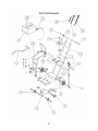
1
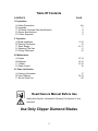
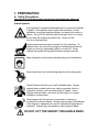
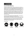
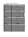
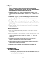
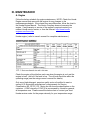
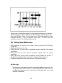
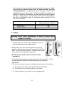
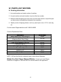
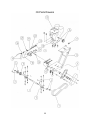
OWNERS
MANUAL
Small Concrete Saw
MODEL:
C9
FORM <<7418
3/2005
WARRANTY
Norton warrants all products manufactured by it against defects in
workmanship or materials for a period of one (1) year from the date of
shipment to the customer.
The responsibility of Norton under this warranty is limited to
replacement or repair of defective parts at Norton's Gainesville,
Georgia factory, or at a point designated by it, of such part as shall
appear to us upon inspection at such point, to have been defective in
material or workmanship, with expense for transportation borne by
the customer.
In no event shall Norton be liable for consequential or incidental
damages arising out of the failure of any product to operate properly.
Integral units such as gasoline engines, electric motors, batteries,
tires, transmissions, etc., are excluded from this warranty and are
subject to the prime manufacturer's warranty.
This warranty is in lieu of all other warranties, expressed or implied,
and all such other warranties are hereby disclaimed.
Important: Before placing equipment in operation, record the following
information.
MODEL:_________ SERIAL NO.___________
PURCHASE FROM: _____________________
ADDRESS: ____________________________
CITY_______ STATE ______ ZIP ________
TELEPHONE NO. ______________________
Before using this equipment, make sure that person using it
read and understand the instructions in this owner’s manual.
2
Table Of Contents
CONTENTS
PAGE
I. Preparation
A. Safety Precautions
B. Assembly
C. C9 Series Concrete Saw Specifications
D. Engine Specifications
E. Pointer Alignment
4-6
7
8
9
9
II. Operation
A. Blade Installation
B. Starting The Engine
C. Water Supply
D. Operating The Saw
E. Cutting Technique
9-10
10
10-11
11
12
III. Maintenance
A. Engine
B. Bearings
C. V-Belts
D. Depth Control
13-14
14-15
15-16
16
IV. Parts List Section
A. Ordering Information
B. Parts Drawing
C. Service Parts List
17
18-19
20
Read Owners Manual Before Use
Safety Alert Symbol: Information Following This Symbol Is Very
Important.
Use Only Clipper Diamond Blades
3
I. PREPARATION
A. Safety Precautions
Important! The following safety precautions must always be observed.
Hazard Symbols
Fuel (gasoline) is extremely flammable and its vapors can explode
if ignited. Store gasoline only in approved containers, in wellventilated, unoccupied approved areas, and away from sparks or
flames. Do not fill the fuel tank while the engine is hot or running.
Do not start the engine near spilled fuel. Never use the
fuel as a cleaning agent
Engine components can get extremely hot from operation. To
prevent burns, do not touch the engine or related parts while the
engine is running or immediately after it is turned off. Never
operate the engine with any heat shields or guards removed.
Keep all guards in place when operating any piece of equipment
Keep hands, feet, hair, and clothing away from all rotating parts
Lethal Exhaust Gas use only in well ventilated areas. Engine
exhaust gases contain poisonous carbon monoxide, which is
orderless, colorless, and can cause death if inhaled. Avoid
inhaling exhaust fumes, and never run the engine in a closed
building or confined area
Never tamper with the governor components of settings to
increase the maximum speed. Severe personal injury and damage
to the engine or equipment can result if operated at speed above
maximum. Always obey the maximum speed rating of blade.
DO NOT LIFT THE SAW BY THE HANDLE BARS
4
Dust and Silica Warning
Grinding/cutting/drilling of masonry, concrete, metal and other materials can
generate dust, mists and fumes containing chemicals known to cause serious or
fatal injury or illness, such as respiratory disease, cancer, birth defects or other
reproductive harm. If you are unfamiliar with the risks associated with the
particular process and/or material being cut or the composition of the tool being
used, review the material safety data sheet and/or consult your employer, the
material manufacturer/supplier, governmental agencies such as OSHA and
NIOSH and other sources on hazardous materials and make certain to comply
with all product warnings and instructions for the safe and effective use of the
material being cut. California and some other authorities, for instance, have
published lists of substances known to cause cancer, reproductive toxicity, or
other harmful effects.
Control dust, mist and fumes at the source where possible. In this regard use
good work practices and follow the recommendations of the
manufacturer/supplier, OSHA/NIOSH, and occupational and trade associations.
Water should be used for dust suppression when wet cutting is feasible. When
the hazards from inhalation of dust, mists and fumes cannot be eliminated
through engineering controls such as either vacuum and/or water mist, the
operator and any bystanders should always wear a respirator approved by
NIOSH/MSHA for the material being cut.
Use Approved:
Eye Protection
Hearing
Protection
Respiratory
Protection
5
Head Protection
1. Before mounting any blade on the saw, the blade should be inspected for
any damage which might have occurred during shipment, handling or
previous use.
2. The blade collars and arbors should be cleaned and examined for
damage before mounting the blade.
3. The blade must be properly fitted over the arbor with the drive pin on the
outside collar projecting through the drive pin hole on the blade and
inside collar.
4. The blade shaft nut, which is a left-hand thread nut, must be tightened
securely against the outside blade shaft collar.
5. The blade must be operated within the specified maximum operating
speed listed on the blade.
6. Turn water control valve to full to provide adequate coolant (4 to 6
gallons per minute) for diamond blades and wet cutting abrasive blades.
Insufficient coolant could result in severe blade breakage or diamond
segment separation.
7. The blade guard must be in place with the nose guard down and locked
when the saw is running.
8. The operator should wear safety glasses and any other appropriate
safety equipment.
9. When starting the saw, the operator should stand away and to the side of
the blade.
10. If for any reason the saw should stall in the cut, raise the blade out of
the cut. Check the outside blade shaft collar and nut for tightness.
Inspect the blade for damage before restarting the saw. Use caution
when resuming a cut. Be certain that the blade is in alignment with the
previous cut.
11. During cutting operations, do not exert excess side pressure on the
handles as a method of steering. Do not force the blade into the cut by
lowering the blade too fast or by pushing the saw too fast.
You Are Responsible For Your Safety!!!
6
I. PREPARATION
B. Assembly
The compact concrete saws are shipped completely assembled and ready for
use except for diamond blade, gasoline, oil, and handle bar. Inspect the saw
for shipping damage. If any damage is found, contact the shipper
immediately and file a freight claim. The Norton Company is not responsible
for any freight-related damages. Remove the saw from the pallet. Reverse
the position of the handlebars so that the handle bar sticks out towards the
operator. Adjust the handlebars to the desired height. Attach the handlebars
to the saw with the supplied hardware. Read and understand the remaining
sections of this Owners Manual. NOTE: Do not install the blade until it is
time to use the saw. ANSI regulations prohibit the transportation of any
concrete saw with the blade installed.
7
C. C9 Series Concrete Saw Specifications
Dimensions/Weight
Length (Working)
Length (Transport)
Width
Height
Weight
Engine
Engine Mfg.
Model
Spec No.
Engine Type
Horse Power
Max Torque
Cooling System
Oil Capacity
Fuel Capacity
Fuel Type
Low Oil Sensor
Air Filtration
Characteristics
Max Blade
Depth of Cut
14” (356 mm)
12” (305 mm)
Arbor Bore
Blade Shaft Locking Device
Blade Shaft Speed
Depth Control
Depth Lock
Depth Gauge
Number Of V-Belts
Blade Guard Type
Right or Left Side Cutting
Lifting Bale
Handle Bars
Water Tank
Water Tank Capacity
Water Hose Connector
Recessed Rear Wheels
Sound pressure1
Sound power1
50” (1270 mm)
40.5” (1029 mm)
20.5” (521 mm)
41” (1041 mm)
195 lbs (88.6 kg)
Honda
GX270
GX270K1QXC9
Single Cylinder 4 Cycle
9 hp (6.65 kW) @ 3,600 rpm
19.5 ft-lbs (26.5 Nm, 2.7 kg-m) @ 2,500 rpm
Air
1.1 liter (1.16 US qt)
6.5 liter (1.79 US gal)
Unleaded Gasoline (86 pump octane)
Yes
Four Stage Cyclone
∅14” (356 mm)
5.75” (146 mm)
4.75” (121 mm)
3.75” (95 mm)
1” (25.4 mm)
Machined Into Flats Of Tight Collar
2850 rpm
Hand Wheel With Screw Feed
Standard
Customer Installed Accessory
3
Hinged, All Steel Construction
Yes
Built In
Adjustable, Stays Level At All Times
Standard
5.28 US Gallons (20 liter)
Standard Garden Hose With Flow Control Valve
Standard
88 db(A)
105 db(A)
1) the sound measures have been made following pr EN 12638, Annex A;
8
2)“ Floor sawing, grooving and milling machines – Safety “
D. Engine
Prior to attempting to operate the engine, read the information
contained in the engine owner's manual. An engine owners manual is
supplied with every gasoline powered concrete saw.
1. Check Oil: Add oil if low. Refer to the engine owner's manual for the
recommended SAE viscosity grades. Capacity of oil is 1.1 liters (1.16 US
qt)
2. Check Fuel: Fill if low. Use only unleaded gasoline with a pump sticker
octane rating of 86 or higher is recommended. Never use an oil and
gasoline mixture!
3. Air Cleaner: Never run the engine without the air cleaner! Rapid engine
wear will result from contaminants being drawn through the carburetor and
into the engine.
4. Engine Starting: Refer to the engine owner's manual for proper engine
starting procedure.
E. Pointer Alignment
1. Use a straight edge, and carefully mark a line 12 feet long on a smooth
level surface.
2. Place the saw blade on the marked line, move the saw to the center of the
marked line and then lower the blade until it is about 1/16” above the
marked line
3. Measure from each end of the saw frame to insure that the frame is
parallel to the marked line. Adjust the saw as needed.
4. With the blade centered on the marked line and the saw frame parallel to
the marked line, lower the front pointer.
5. Adjust the pointer by bending it until is aligned with the marked line.
II. OPERATION
A. Installing the Blade
1. Disconnect the spark plug and then insert the Blade Shaft Locking Pin
into the Blade Shaft Locking hole.
9
2. Remove the blade shaft nut, (Turn clockwise) , and remove the outside
collar.
3. Clean off any foreign particles on the clamping surfaces of both collars
and on the mounting surface of the blade.
4. Place the blade on the blade shaft, lining up the drive pin hole in the
blade with the drive pinhole in the inside collar.
Use only Clipper Diamond Blades. This machine was not
designed for the use with abrasive blades.
5. Slide the outside blade shaft collar onto the blade shaft . The drive pin
on the outside collar must project through the drive pin hole in the
blade and into the inside collar.
6. Tighten the blade shaft nut (counter-clockwise) securely against the
outside collar and remove the Blade Shaft Locking Pin.
7. Reconnect the spark plug.
Blades Use Only Clipper Diamond Blades
B. Starting the Engine
1. Refer to the engine owner's manual for the proper starting procedures.
2. Always cut with engine rpm in the full throttle setting.
C. Water Supply
Pressurized source: Turn the water control to full "ON" when using wet
cutting blades. The required flow rate is 4-6 gallons per minute.
Water Tank on saw: This supply is designed for use with dry blades to
keep the dust levels down. The tank will not supply the proper water flow
rates when used with wet cut only blades. Do not drink the water from this
tank. Fill the tank with water only. Close the water tank valve. Attach the
saws water supply hose to the tank outlet. Fill the tank with water. The
capacity of the tank is 5 US Gallons. When you are ready to cut, adjust
the water supply rate until a fine mist or a slow trickle is made. The
use of water greatly decreases the amount of dust produced during the
cutting process, aids in the cooling of the blade, and provides additional
10
stability. The water tank adds additional blast (weight) to the machine,
which aids in keeping the diamond blade in the cut and reducing
vibrations. We recommend that the water tank to be filled with water at all
time the machine is in use.
•
•
Use Only Water In The Water Tank
Do Not Drink From The Tank
D. Operating the Saw
1. For blade installation instructions see section II. Operation sub heading A.
Installing the Blade. For the engine starting instructions, see the Engine
manual and follow the instructions located in section II. Operation sub
heading B. Starting the Engine.
2. Check the Engine Oil level.
3. Raise the saw to the full upright position. Do not let the blade come in
contact with the ground.
4. Maneuver the saw to the desired starting point.
5. If wet cutting, connect the water supply to the saw.
6. Follow the instructions for starting the engine found in the Engine manual.
7. If wet cutting, turn on the water supply at the source and then open the
water valves on the saw. Make sure that there is a minimum of 4-6 gallons
per minute of water flow!!
8. Be sure the engine is running at full throttle!!!
9. Slowly lower the blade by rotating the hand wheel clockwise until the
desired depth of cut is reached. Use a reasonable rate of feed. Do not
force the blade into the cut!!
10. When the end of the cut is reached, slowly raise the blade out of the cut
by rotating the Hand Wheel counter-clockwise until the blade is at least
one (1) inch above the ground.
12. Only move the saw in reverse with the blade in the raised position.
11
13. When moving the saw to a new location, be sure the blade is not
touching the ground. Always pay close attention to where you are
moving and where the blade is at all times.
E. Cutting Technique
Lower the blade into the concrete to the required depth by turning the hand
wheel clockwise.
Reduce the forward pressure if the saw begins to stall.
Note: For deeper cuts (4 inches or more), several cuts should be made in
incremental steps of 1-1/2 to 2 inches until the desired depth of cut is
reached.
Push the saw steadily forward using the front pointer as a guide. Exert
enough forward pressure so that the engine begins to labor, but does not
slow down. If the saw begins to stall, reduce the forward movement until full
rpm is restored to the blade. If the saw stalls, raise the blade out of the cut
before restarting. Avoid excessive side pressure or twisting of the blade in
the cut.
Additional Guide Lines For Sawing:
•
Understand and follow all of the instructions in this owner’s manual.
•
If wet cutting, turn on the water supply so that there is a minimum of 4-6
gallons per minute of water flow!!
•
In critically hard aggregate, more than a single pass may be needed to cut
the desired depth.
•
If the saw stalls in the cut, immediately stop the forward speed and raise
the blade out of the cut. If this is not done the belts can fail or the blade
may be damaged.
•
Go slowly with a new blade until it opens up, that is, until the diamonds
can be seen and felt.
12
III. MAINTENANCE
A. Engine
Follow the below schedule for engine maintenance. NOTE: Check the Honda
Engine manual that came with the engine for any changes to the
maintenance schedule. If the charts have any differences, follow the chart in
the Honda Engine Manual. The Norton Company does not warranty the
engine. If any warranty or service of the engine is required contact your
nearest Honda service center, or from the Internet: http://www.hondaengines.com/home.htm
Honda engine ( refer to owner's manual for complete maintenance.)
Check the engine oil level before each use when the engine is cool and the
engine is level. Add oil if the level is low. The oil level should be within the
operating range (see the eninge owner’s manual for details).
Only use a high-detergent, premium quality motor oil certified to meet or
exceed U.S. automobile manufacturer’s requirements for Service
Classification SG, SF/CC, CD. Motor oils will show the classification on the
container. A SAE viscosity of 10W-30 is recommend by Honda for general,
all temperature use. Please consult the below chart or contact your local
Honda service center for the proper viscosity for your temperature range.
13
Always refer to the engine manual for more detailed information on checking
the oil, changing oil, and oil capacity, air filter changes, and fuel type to use.
Use only Honda air filters. Do not clean the air filter with gasoline or other
flammable solvents. A fire or explosion could result. To clean, follow the
instructions found in the Honda engine manual.
Dry Cutting Engine Maintenance
9 When operating the engine in dry cutting or dusty environments the following
is required:
9 Engine oil changed more often.
9 Every 50 hours (or more often if conditions require) clean all of the engine
cooling fins.
9 Every 25 hours (or more often if conditions require) clean the engine
precleaner.
9 Every 100 hours (or more often if conditions require) replace the air filter. If
the engine is equipped with a reusable air cleaner, clean and re-oil it.
9 Check and clean the air filter after each use. Replace as needed.
B. Bearings
Re lubrication type bearings must be relubricated daily to assure long life.
The grease used should conform to the NLGI grade two and be free of
any chemical impurities such as free acid or free alkali, dust, rust, metal
particles or abrasives.
14
For best results, bearings should be relubricated while in operation. Note:
Due caution for personal safety must be observed when servicing
rotating equipment. The grease should be pumped in slowly until a
slight bead forms around the seals. This bead, in addition to acting as an
indicator of adequate relubrication, provides additional protection against
the entry of foreign matter. If necessary to relubricate while the bearing is
idle refer to relubrication table for maximum grease capacity for the
various size bearings.
Shaft Size
Maximum Grease Capacity of
Bearing Chamber in Ounces
1/8
3/8
5/8
1/2"' to 3/4"
7/8" to 1-3/16"
1-1/4" to 1-1/2"
C. V-Belts
Warning: Never make adjustments to belts or pulleys while
engine is running!
1. The best tension for a belt drive is the lowest tension at
which the belts will not slip under full load.
2. Simply take up the drive until the belts are snug in the
grooves. Run the drive for about 15 minutes to "seat" the
belts. Then impose the peak load. If the belts slip, tighten
them until they no longer slip at peak load.
3. Remember, too much tension shortens belt and
bearing life!
FIGURE 1
4. Check the belt tension frequently during the first day of operation. Check
the belt tension periodically thereafter and make any necessary
adjustments.
5. The two most common causes of misalignment are shown in the drawing.
a). The engine drive shaft and the blade shaft are not parallel.
b). The pulleys are not located properly on the shafts.
6. To check alignment, all you need is a steel straight edge.
15
FIGURE 2
7. Line up the straight edge along the outside face of both pulleys as shown
in the drawing.
8. Misalignment will show up as a gap between the pulley face and the
straight edge.
9. Make sure that the width of the outside land (area between the belt and
the edge of the pulley) is equal on both pulleys.
D. Depth Control
The depth control (raising screw) consists of a threaded rod, which feeds into
a brass nut. In order to keep the two parts working smoothly it is necessary
to keep the rod free from dirt and sludge as much as possible. Cleaning the
threaded rod with a rag after each use will prevent sludge from collecting in
the tube assembly and protect the threads. It is a good practice to keep the
raising screw threads lubricated, as the slurry generated during cutting will
cause premature thread wear.
The bearing used to support the raising screw should be checked after each
use to make sure it is turning freely and lubricated. If the bearing requires re
lubrication lithium base grease is recommended.
16
IV. PARTS LIST SECTION
A. Ordering Information
1. List model number and serial number of machine.
2. List part number and serial number of part not the item number.
3. Wherever alternate parts are shown due to product improvement, inspect the part
you have and provide additional description as necessary.
4. Specify mode of shipping desired, such as, parcel post, truck, U.P.S., best way,
etc.
For the nearest Clipper distributor call 1-800-554-8003
Common Replacement Parts
Description
Belts V-belts XPA 710LW (set of 3)
Blade Shaft Nut ¾-16 Left Hand Thread
(Operators Right Side Of Saw)
Collar Tight (Operators Right Side)
Collar Loose Assembly (With Pin)
Drive Pin ∅3/8 x 1
Bearing Blade Shaft (1)
Front Wheel Complete (1)
Rear Wheel (1)
Wrench 1-1/2”
Wrench 32mm
Wrench 17mm
Part Number
83480
227156
227159
227247
227154
72474
80992
80991
105377
82910
72279
NOTE: All Parts Are Sold As Individual (each) Unless Noted Otherwise
Blades Use Only Clipper Diamond Blades. Contact your local Clipper
Distributor or Clipper at 1-800-554-8003 for the best blade for the application.
17
C9 Parts Drawing
18
C9 Parts Drawing
19
Service Parts List C9
Service Parts List C9
POS
Description
Req
P/N
1
2
3
Blade Shaft (Alone)
Nut Blade Shaft ¾'' Lefthand Thread
Bearings Blade Shaft (1) with Hardware
Screw M12 x 70 1.75 DIN931(ea)
Washer M12 DIN125 (ea)
Lock Washer M12 DIN127 (ea)
Nut M12 1.75 DIN934(ea)
Screw M12 x 45 1.75 DIN933 (ea)
Blade Shaft Pulley
Collar Tight (Inner Collar)
Collar Loose Assembly (With Pin)
Belts XPA 710 LW (Set of 3)
Belt Guard Complete
Screw M10 x 25 1.5 DIN931 (ea)
Washer M10 DIN125 (ea)
Lock Washer M10 DIN125 (ea)
Nut M10 1.5 DIN934 (ea)
Cage Nut M10 1.5(ea)
Nut Close M10 Hex Acorn Nut (ea)
Washer M10 DIN125 (ea)
Blade Guard Flap w/Hardware
Screw M10 x 25 1.5 DIN933 (ea)
Washer M10 Large Dia DIN9021(ea)
Washer M10 DIN125 (ea)
Nut M10 1.5 DIN934 (ea)
Blade Guard Complete w/Hardware
Screw M10 x 35 1.5 DIN933 (ea)
Nut M10 1.5 DIN934 (ea)
Stop Switch
Belt Tensioning Screws (Compelte Set)
Screw M10 x 80 1.5 DIN931 (ea)
Eye Bolt M10 x 40 1.5 DIN444 (ea)
Nut M10 Thin 1.5 DIN439 (ea)
Nut M10 1.5 DIN934 (ea)
Lock Washer M10 DIN127 (ea)
Washer M10 DIN125 (ea)
Engine Frame Welded (No Hardware)
Motor Pulley Complete
Honda Motor 9 HP GX270
Y piece
Adapter ½ Hose Barb to ¾” Garden
Hose
Motor Fixing Plate w/Hardware
Nut M10 1.5 DIN934 (ea)
Lock Washer M10 DIN127 (ea)
Washer M10 DIN125 (ea)
Washer M10 Large Dia DIN9021(ea)
Water Nozzle (2)
Axle Blade Guard
Blade Guard Nut
Valve Ball 1/2" Brass
Fit 1/2mpt X3/4 F Garden Hose Swivel
1
1
2
2
16
8
4
2
1
1
1
1
1
3
5
3
3
3
2
1
2
2
2
2
1
1
1
1
1
2
2
2
6
4
6
1
1
1
1
1
83280
227156
72474
27175
27505
27581
27007
27088
83511
227159
227247
83480
83485
149044
27504
27502
27006
27189
30177A
27504
81164
149044
27504A
27504
27006
83481
27030A
27006
227115
80994
27068
27270
27004
27006
27502
27504
83279
73230
73110
72286
232076
1
8
8
4
4
1
1
1
1
1
83482
27006
27502
27504
27504A
82998
83490
83366
107859
227116
4
5
6
7
8
9
10
11
12
13
14
15
16
17
18
19
20
21
22
23
POS
Description
24 Fit Barb Hose 3/4MPT X 1/2M
25 RaiseTube (No Hardware)
Screw M12 x 80 1.75 DIN933 (ea)
Nut Lock M12 1.75 DIN985 (ea)
Nut M12 1.75 DIN934 (ea)
26 Wrench 1''1/2
27 Wrench 32mm
28 Wrench 17mm
29 Handle Grip (ea)
30 Tank Cap
31 Tap-Water Tank
32 Water Tank Complete w/Cap
33 Raise Axle w/Hardware
Screw M10 x 60 1.5 DIN931 (ea)
Nut M10 1.5 DIN934 (ea)
34 Front Wheel Complete (ea)
Washer M16 DIN127 (ea)
Pin Cotter 5/32 x 1 (ea)
35 Rear Wheel 200mm x 20mm (ea)
Washer M20 DIN125 (ea)
Pin Cotter 5/32 x 1-1/2 (ea)
36 Rear Axle Fixing Flat (ea)
Screw M10 x 30 1.5 DIN933 (ea)
Nut M10 1.5 DIN934 (ea)
Lock Washer M10 DIN125 (ea)
Washer M10 DIN125 (ea)
37 Ring Diam. 20
38 Water Tank Bracket w/Hardware
Screw M10 x 25 1.5 DIN933 (ea)
Nut M10 1.5 DIN934 (ea)
Lock Washer M10 DIN125 (ea)
Washer M10 DIN125 (ea)
39 Handle For Hand Wheel (No
Hardware)
40 Hand Wheel with Handle and
Hardware
Nut Closed M16 2 DIN1587 (1)
Washer M16 DIN125 (1)
Lock Washer M16 DIN127 (1)
41 Guide-A-Cut
42 Handle Bar Complete w/Hardware
Screw M10 x 25 1.5 DIN933 (ea)
Screw M10 x 20 1.5 DIN933 (ea)
Nut M10 1.5 DIN934 (ea)
43 Bearing w/Hardware
Screw M10 x 30 1.5 DIN933 (ea)
Nut M10 1.5 DIN934 (ea)
Lock Washer M10 DIN125 (ea)
Washer M10 DIN125 (ea)
44 Stop Ring A20
45 Depth Lock
46 Depth Screw w/Key
Req
P/N
1
1
1
2
4
1
1
1
2
1
1
1
1
2
2
2
4
2
2
2
2
2
4
4
4
8
1
1
2
2
2
4
1
9600017
83276
27088
27017
27581
83314
82910
72279
213633
82794
72357
83357
83486
27030B
27006
80992
27532
27030C
80991
27504B
27030D
80998
27030
27006
27502
27504
80999
83277
149044
27006
27502
27504
73428
1
76357
1
1
1
1
1
1
1
2
1
2
2
2
4
1
1
1
27176
27532
27545
80448
83484
149044
27106
27006
76670
27030
27006
27502
27504
82789
83354
82788
NOTES
Norton Construction Products
PO Box 2898
Gainesville, GA 30503
Phone: 800-554-8003 or 770-967-3954
(8:00 A.M. to 7:00 P.M. Eastern Time)
Fax: 800-443-1092 or 770-967-7287