1
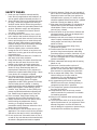
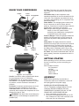
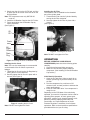
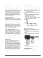
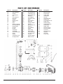
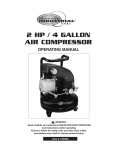
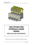
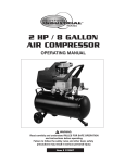
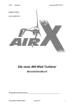
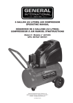
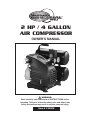
2 HP / 4 GALLON
AIR COMPRESSOR
OWNER'S MANUAL
WARNING:
Read carefully and understand all INSTRUCTIONS before
operating. Failure to follow the safety rules and other basic
safety precautions may result in serious personal injury.
Item # 123008
READ ALL INSTRUCTIONS
BEFORE OPERATING
SPECIFICATIONS
Motor...................................120V ~ 60Hz
HP.......................................2
Weight.................................59.5 lbs
Tank Capacity .....................4 Gallon
Air Pressure ........................115 psi
CFM ....................................5.5 CFM@40 PSI
............................................3.5 CFM@90 PSI
CSA Listed ..........................
SAVE THESE INSTRUCTIONS
Thank you for purchasing your Northern IndustrialTM
Air Compressor. Before attempting to operate your
new tool please read these instructions thoroughly.
You will need these instructions for the safety
warnings, precautions, assembly, operation and
maintenance procedures.
WARNING: The warnings, cautions and
instructions discussed in this instruction manual
cannot cover all possible conditions or situations
that could occur. It must be understood by the
operator that common sense and caution are
factors which cannot be built into this product, but
must be supplied by the operator.
TABLE OF CONTENTS
Description
Page #
Specifications .......................................1
Safety rules ..........................................2
Know Your Tool.....................................3
Getting Started .....................................3
Assembly ..............................................3
Operation..............................................4
Maintenance .........................................6
Troubleshooting....................................7
Parts List and Diagram.........................8
1
SAFETY RULES
16. Check for damage. Check your tool regularly. If
part of the tool is damaged it should be carefully
inspected to make sure that it can perform its
intended function correctly. If in doubt, the part
should be repaired. Refer all servicing to a qualified
technician. Consult your dealer for advice.
17. Keep away from flammables. Do not attempt to
operate this tool near flammable materials or
combustibles. Failure to comply may cause
serious injury or death.
18. Store idle tools out of the reach of children and
untrained persons. Tools may be dangerous in
the hands of untrained users.
19. Maintain tools with care. Keep tools sharp and
clean. Properly maintained tools, with sharp
cutting edges, are less likely to bind and are
easier to control.
20. Never exceed the pressure rating of any
component in system.
21. Protect material and air lines from damage or
puncture. Keep hose and power cable away
from sharp objects, moisture, chemicals, oil, etc.
22. Check condition of hoses before each use. Do
not use a damaged hose. If hose is damaged,
replace immediately.
23. Read, understand and comply with all warning
labels on unit.
24. Drain tank of moisture after each use. If
Compressor is not to be used for extended
periods of time, leave tank drain valve open to
allow moisture to completely drain from tank.
25. Do not tamper with Safety Valve. The Safety
Valve is factory set for your model air
compressor. Any user adjustments to Safety
Valve will automatically void warranty.
26. Air compressors get hot while in operation.
NEVER touch the motor, discharge tubing or
compressor pump while in operation.
27. The Compressor operates automatically while
the motor is turned on.
28. Compressed air from the unit may contain
carbon monoxide. Air produced is not suitable
for breathing purposes.
29. Always use a respirator when spraying paint
or chemicals.
30. The air pressure switch is set at the factory for
optimum performance of your equipment. Never
attempt to bypass or remove this switch as
serious damage to equipment or personal injury
could result from excessive air pressure.
1. Know your tool. Read this manual carefully.
Learn the tool’s applications and limitations, as
well as specific potential hazards peculiar to it.
2. Ground all tools. If the tool is equipped with threepin plug, it should be plugged into a three-pin
electrical socket. Never remove the ground pin.
3. Avoid body contact with grounded surfaces such
as pipes, radiators, ranges, and refrigerators.
There is an increased risk of electric shock if
your body is grounded.
4. Do not expose tool to moisture. Don’t use this
tool in damp or wet locations. Keep out of rain.
5. Do not abuse cord. Never use the cord to carry
tools or pull the plug from an outlet. Keep cord
away from heat, sharp edges or moving parts.
Replace damaged cords immediately. Damaged
cords increase the risk of electric shock.
6. Remove adjusting keys or wrenches before
turning the tool on. A wrench or key that is left
attached to a moving part of the tool may result
in personal injury.
7. Keep work area clean and well lit. Cluttered or
dark work areas invite accidents.
8. Keep children away. All children should be kept
away from the work area. Never let a child
handle a tool without strict adult supervision.
9. Do not operate this tool if under the influence of
alcohol or drugs. Read warning labels on
prescriptions to determine if your judgment or
reflexes are impaired while taking drugs. If there
is any doubt, do not attempt to operate.
10. Use safety equipment. Eye protection should be
worn at all times when operating this tool. Use
ANSI approved safety glasses. Everyday
eyeglasses are NOT safety glasses. Dust mask,
non-skid safety shoes, hard hat, or hearing
protection should be used in appropriate conditions.
11. Wear proper apparel. Loose clothing, gloves,
neckties, rings, bracelets, or other jewelry may
present a potential hazard when operating this
tool. Please keep all apparel clear of the tool.
12. Don’t overreach. Keep proper footing and
balance at all times when operating this tool.
13. Always disconnect the tool from power source
before making any adjustments, storing,
servicing, or changing accessories. Such
preventative safety measures reduce the risk of
starting the tool accidentally.
14. Do not force tool. Use the correct tool for your
application. The correct tool will do the job better
and safer at the rate for which it was designed.
15. Do not use the tool if the switch does not turn it
on and off. Any tool that cannot be controlled with
the switch is dangerous and must be repaired.
2
KNOW YOUR COMPRESSOR
Handle
Power
Switch
Air Filter: This heavy duty metal air filter keeps
your compressor running cleanly, by filtering out
impurities.
Oil Breather Cap: As the compressor motor
operates pressurized air must be released from the
crank case. The oil breather cap allows built up air
to escape, while shielding your air compressor from
airborne impurities.
Power Switch: The red tipped power switch turns
the air compressor on and off. When switch is
pulled up, compressor is turned ON. When switch is
pushed down, compressor is turned OFF.
Note: Always make sure that compressor Power
Switch is in the OFF position before
performing any maintenance or plugging the
compressor into a power supply.
Pressure Gauges: These dual gauges indicate the
amount of air pressure built up in the air tank, as
well as the air pressure being delivered to the air
chuck.
Safety Valve: The Safety Valve device relieves
pressure from the Air Tank in the event of excessive
pressure build up. The Safety Valve is preset at
factory. Do not attempt to make any adjustments to
the Safety Valve. Periodically pull the ring on the
Safety Valve end to check that it is working properly.
Air Tanks: Two powder coated steel tanks, with a 4
gallon capacity, stores the compressed air until it is
needed.
Air Regulator
Air
Filter
Oil
Breather
Cap
Tank
Drain
Valve
Safety
Value
Air
Chuck
Pressure
Gauges
Air
Tanks
GETTING STARTED
Before operating your tool, check the contents of
the box to make sure you have everything you
will need.
Items included in the box:
Air Compressor
Air Filter
Oil Breather Cap
Bottle of Oil
Owner’s Manual
Figure 1. Air Compressor
Handle: Convenient, rubber gripped handle allows
for easy transport of your air compressor.
Air Regulator: The air regulator controls the air
flow pressure. Turn regulator clockwise to increase
air pressure, counter-clockwise to decrease air
pressure.
Air Chuck: Convenient quick disconnect air chuck
allows for fast easy connection to an air hose.
Tank Drain Valve: The Tank Drain Valve can be
opened to allow moisture and compressed air to be
released from the Air Tank.
ASSEMBLY
NOTE: Before performing any assembly or
maintenance make sure compressor is turned off
and unplugged from the power supply.
Installing the Oil and Oil Breather Cap
Your air compressor is shipped without oil in the
crankcase. BEFORE STARTING THE AIR
COMPRESSOR YOU MUST ADD OIL TO THE
CRANKCASE AS DESCRIBED BELOW:
1. Place compressor on level ground.
2. Remove the Oil Shipping Plug from the Oil Fill
hole, located on the top of the crankcase cover
at the rear of the air compressor.
WARNING! Tank Drain Valve should always be
opened slowly to avoid damage to equipment and
possible injury.
3
Installing the Air Filter
The metal Air Filter is installed into the threaded
port of the cylinder head.
1. Thread the Air Filter into the Cylinder Head by
turning the Air Filter clockwise.
2. Securely tighten the Air Filter in place with a
wrench.
(See Figure 4)
3. Slowly pour the oil into the Oil Fill hole, until the
oil level rises to the center of the red dot on the
Oil Sight Glass.
Note: This compressor uses only SAE 5W-30
motor oil.
4. Install the Oil Breather Cap into the Oil Fill hole.
5. Firmly hand tighten the Oil Breather Cap by
turning clockwise.
(See Figure 2)
Oil
Fill
Crankcase
Oil
Sight
Glass
Figure 4. Installing the Air Filter
Drain
Plug
Note: DO NOT over tighten Air Filter.
OPERATION
Figure 2. Installing the Oil & Oil Breather Cap
BEFORE OPERATING YOUR NEW AIR
COMPRESSOR please check the following points
carefully:
1 Check that all nuts and bolts are secure.
2. Make sure oil has been properly added to
compressor. (See Installing Oil and Oil Breather
Cap section.)
Installing the Air Chuck
Note: The use of a sealant tape is recommended
on the threads of the Air Chuck to prevent air
leakage.
1. Thread the Air Chuck into the Air Regulator by
turning the Air Chuck clockwise.
2. Securely tighten the Air Chuck in place with a
wrench. (See Figure 3)
Initial Start-Up Procedure
1. Open the Air Tank Drain Valve to permit air to
escape, preventing air pressure buildup in the
air tank.
2. Run the compressor for a minimum of 20
minutes in this “no-load” position to lubricate the
piston and bearings.
3. Close Air Tank Drain Valve. Your compressor is
ready for use.
Depending on the CFM draw of the tools being
operated, your new Air Compressor can be used for
operating paint sprayers, air tools, grease guns,
airbrushes, caulking guns, abrasive blasters, tire &
plastic toy inflation, spraying weed killer and
insecticides, etc. Proper adjustment of the Air
Pressure Regulator is necessary for all of these
operations. Refer to the air pressure specifications
provided with the tool you are using.
Figure 3. Installing the Air Chuck
Note: DO NOT over tighten Air Chuck.
4
General Overview
To compress air, the piston moves up and down in
the cylinder. On the down stroke air is drawn in
through the valve inlet. The discharge valve remains
closed. On the upstroke of the piston air is
compressed. The inlet valve closes and air is forced
out through the discharge valve, through the check
valve, and into the air tank. Working air is not
available until the compressor has raised the tank
pressure above that required at the air service
connection. The air inlet filter openings must be
kept clear of obstructions, which could reduce air
delivery of the compressor.
Attaching an Air Hose
Your Air Compressor is supplied with a 1/4" Quick
Disconnect Air Chuck. Once you have correctly
installed the Air Chuck (See Installing the Air Chuck
on p.4) your compressor will be ready to accept air
hoses equipped with 1/4" male air couplers.
Note: Use only air hoses rated for use with 115psi
air pressure or higher.
To install an air hose, equipped with a 1/4" male
coupler:
1. Pull back on Air Chuck outer sleeve to allow
coupler to be fully inserted into Air Chuck.
2. Insert coupler into Air Chuck.
3. Release outer sleeve of Air Chuck.
4. Verify that air hose is securely connected to Air
Chuck by pulling lightly on air hose.
(See Figure 5)
Installation and Location
Locate the compressor in a clean, dry and well
ventilated area. The compressor should be located
12 to 18 inches from walls or any other obstruction
which would interfere with airflow. Place the
compressor on a firm, level surface. The
compressor is designed with heat dissipation fins
which allow for proper cooling. Keep the fins (and
all other parts which collect dust or dirt) clean. A
clean compressor runs cooler and provides longer
service. Do not place rags, containers or other
material on top of the compressor.
Figure 5. Attaching an Air Hose
Adjusting the Air Pressure
Your Air Compressor is supplied with an Air
Pressure Regulator. This Regulator adjusts the air
pressure.
To increase air pressure, turn Air Regulator
clockwise.
To decrease air pressure, turn Air Regulator
counterclockwise.
Connecting to Power Source
This air compressor is designed to operate on a
properly grounded 120 volt, 60Hz, single phase,
alternating current (ac) power source with a fused
20 amp time delayed fuse or circuit breaker. It is
recommended that a qualified electrician verify the
ACTUAL VOLTAGE at the receptacle into which the
unit will be plugged and confirm that the receptacle
is properly fused and grounded. The use of the
proper circuit size can eliminate nuisance circuit
breaker tripping while operating your air compressor.
Extension Cords
For optimum Air Compressor performance an
extension cord should not be used unless
absolutely necessary. If necessary, care must be
taken in selecting an extension cord appropriate for
use with your specific Air Compressor. Select a
properly grounded extension cord which will mate
directly with the power source receptacle and the
Air Compressor power cord without the use of
adapters. Make certain that the extension cord is
properly wired and in good electrical condition.
Maximum length of extension cord should be 50
feet. Minimum wire size of extension cord should be
12 gauge.
(See Figure
6) 6. Adjusting the Air Pressure
Figure
Cold Weather Starting
Temperatures below freezing (32°F) cause the
metal parts of your Air Compressor to contract and
that makes starting more difficult. To assist the Air
Compressor in starting in cold weather, follow
5
compressor.
Changing the Air Compressor Oil
Note: This compressor uses only SAE 5W-30
motor oil.
1. Remove the Drain Plug under the Oil Sight
Glass by turning the nut counter-clockwise with
wrench. (See Figure 2.)
Note: Oil will begin to drain as Drain Plug is
loosened. Place a funnel and oil pan in place
BEFORE loosening Drain Plug.
2. Once Drain Plug is removed, tilt Air Compressor
backwards to allow all of the oil to drain out of
the crankcase.
3. Once oil is drained, replace Drain Plug and
securely tighten in place with a wrench. Be
careful not to overtighten the Drain Plug, as this
could damage the rubber seal.
4. Place Air Compressor on level surface.
5. Remove the Oil Breather Cap.
6. Slowly pour the oil into the Oil Fill hole, until the
oil level rises to the center of the red dot on the
Oil Sight Glass.
7. Install the Oil Breather Cap into the Oil Fill hole.
Firmly hand tighten the Oil Breather Cap by
turning clockwise.
these tips:
1. Try to keep Air Compressor stored in
temperatures above 32° fahrenheit.
2. Open the Air Tank Drain Valve and release all
air pressure from the Air Tank before attempting
to start in cold weather. (After air is released
3. Plug Air Compressor directly into a 120 volt
electrical outlet. Do not use an extension cord
when starting your Air Compressor in cold
weather.
MAINTENANCE
Daily (or before each use)
1. Check oil level
2. Drain condensation from the air tank.
3. Check for any unusual noise or vibration.
4. Be sure all nuts and bolts are tight.
Weekly
1. Clean breather hole on Oil Breather Cap.
Monthly
1. Inspect air system for leaks by applying soapy
water to all joints. Tighten these joints if leaks
are discovered.
Always inspect the tool before use, and make sure
it is in good working condition. Make sure all air
vents are clear, (use compressed air to clean the
machine where possible). Check the power cable to
make sure it is intact and free from cracks, bare
wires etc. Avoid using solvents when cleaning
plastic parts. Most plastics are susceptible to
damage from the various types of commercial
solvents.
6 Months (or after 250 hours of operation whichever comes first)
1. Change Air Compressor Oil.
Note: Change oil more often if Air Compressor is
used near paint spraying operations or in dusty
environments.
Checking the Air Compressor Oil
1. Place Air Compressor on level surface. The oil
level should be at the red dot on the Oil Sight
Glass.
2. If oil level is low, remove Oil Breather Cap and
add enough oil to bring the oil level to the red
dot on the Oil Sight Glass.
3. Replace Oil Breather Cap before starting
6
7
Part No.
01
02
03
04
05
06
07
08
09
10
11
12
13
14
15
16
17
18
19
20
21
22
Description
Plastic Housing
Spring Washer
Washer
Screw M5x14
Fan
Screw M5x115
Rear Cap
Washer
Bearing 6202
Stator
Rotor
Starting Capacitor
Running Capacitor
Bearing 6204
Oil Seal
Nut M8
Crankcase
Crankshaft
Screw M8x16 (left
hand)
Gasket
Crankcase Cover
Oil Sight Glass
Part No.
23
24
25
26
27
28
29
30
31
32
33
34
35
36
37
38
39
40
41
42
43
44
45
Description
Drain Plug
Pan Head Screw
Oil Breather Cap
Spring Washer 8
Washer 8
Screw M8x20
Connecting Rod
Piston
Spring Washer
Piston Pin
Cylinder Gasket
Cylinder
Spring Washer 6
Washer 6
Screw M6x40
Gasket
Sealer Ring
Valve Gasket
Valve Plate Assy
Air Intake Valve
Limit Pin
Cylinder Gasket
Metal Air Filter
8
Part No.
46
47
48
49
50
51
52
53
54
55
56
57
61
62
63
64
65
66
67
68
79
Description
Cylinder Head
Elbow Exhaust
Exhuast Pipe
Check Valve
Unload Pipe
Air Tank
Tank Drain Valve
Rubber Feet
Screw M6x20/ Nut M6
Power Cord
Rubber Gasket
Centrifugal Switch
Rubber Grip
Safety Valve
Pressure Gauge
Pressure Switch
Connector
Pressure Gauge
Regulator
Air Chuck
Frame Assy