1
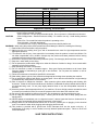
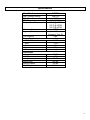
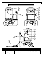
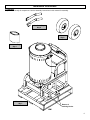
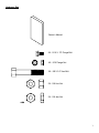
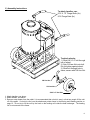
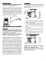
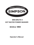
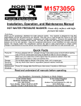
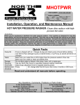
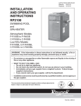
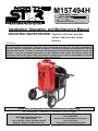
M157494H
ITEM NUMBER: 157494
SERIAL NUMBER:
Proven Performance
Volts:______ Amp:______ Ph:_____
PSI:________ GPM:______
Max. Discharge Temperature:_____________
K-BAR Industries, Faribault, MN, 55021
Installation, Operation, and Maintenance Manual
INDUSTRIAL WATER HEATER: Upgrades cold water pressure
washers into hot water/steam
cleaners.
To the Owner:
Thank you for purchasing a NorthStar water heater. Your machine is designed for long life, dependability, and
the top performance you demand! Take time now to read through this manual so you better understand the
machine’s operation, maintenance and safety precautions. Everyone who operates this machine must read and
understand this manual. The time you take now will prolong your machine’s life and prepare you for its safe
operation. Enjoy the exceptional performance of your NorthStar water heater, the industry leader! The
manufacturer reserves the right to make improvements in design and/or changes in specifications at any time
without incurring any obligation to install them on units previously sold.
Read and understand all manuals before operating.
Any Questions, Comments, Problems or Parts Orders
In the United States
NorthStar Customer Service
Call 1-800-270-0810
Hours: Monday - Friday 7:00 AM to 5:30 PM
Saturday 7:30 AM-11:30 AM Central Time
In the United Kingdom
Call 02392639752
Northern Tool and Equipment Co. (UK) Ltd.
Unit 2, Keel Close,
Portsmouth, Hants PO3 5QD, England
Table of Contents
Important Safety Instructions
Grounding Instructions
Extension Cords
Specifications
Machine Component Identification
Installation Instructions
Operation Instructions
2
3
3
4
5
6-9
10-11
Safety Features
Maintenance Instructions
Moving and Handling Instructions
Long Term Storage
Troubleshooting Guide
Parts Breakdowns
Wiring Diagrams
12
13-15
16
16
17
18-19
20-21
Important Safety Instructions
WARNING
-Risk of Injection or Injury to Persons - Do not direct discharge stream at persons. Do not use a
hose if exterior damage is evident.
-Risk of explosion - Do not spray flammable liquids. Do not operate in a flammable environment.
CAUTION
-Risk of Asphyxiation - Exhaust fumes are deadly. For outdoor use only. Avoid inhaling exhaust
fumes.
-Risk of fire. Do not add fuel when the product is operating or hot.
-Gun kicks back. Hold with both hands.
-To reduce the risk of injury, read operating instructions carefully before use.
WARNING - When using this product, basic precautions should always be followed, including the following:
1.) Read all the instructions before using the product.
2.) Make sure that your existing hose, gun, and all accessories are rated for high temperatures and the
appropriate pressure.
3.) To reduce the risk of injury, close supervision is necessary when the product is used near children. Do
not allow irresponsible use by children. Always stop the product and bleed pressures before leaving
unattended, disconnecting hoses, or servicing.
4.) Know how to stop the product and bleed pressures quickly. Be thoroughly familiar with the controls.
5.) Stay alert - watch what you are doing.
6.) Do not operate the product when fatigued or under the influence of alcohol or drugs. Never smoke while
operating or fueling this machine.
7.) Keep operating area clear of all persons.
8.) Do not overreach or stand on unstable support. Keep good footing and balance at all times. Wear
footwear capable of maintaining a good grip on wet surfaces. Do not place the machine on soft or
unstable ground.
9.) Follow the maintenance instructions specified in all manuals.
10.)Wear safety glasses, gloves, face protection and appropriate clothing when operating the machine.
11.)Do not operate this machine with broken or missing parts. Never alter the manufacturer’s original design
or deactivate any safety device on the machine.
12.)Risk of exposure to dangerous chemicals. Wear protective gloves when handling and cleaning with
chemicals. Follow the chemical manufacturer’s directions. Understand all safety hazards and first aid for
all chemicals being used. Do not pump highly abrasive fluids or use with incompatible chemicals or
solvents.
13.)Know the pressure and temperature limits of your machine. Be sure all high pressure accessories meet
or exceed your machine’s limits. Do not set the pressure relief valve above the machine’s limit.
14.)Do not move this machine by pulling on the hose. Do not attempt to use this machine as a prop.
15.)Do not clean this machine with its own spray. Cleaning should be done with a damp sponge with the
machine OFF.
16.)NEVER attempt to immediately run or re-light the burner if it doesn’t ignite the first time. Unburned oil or
gas may have accumulated causing potential explosion or fire hazard.
17.)Always make sure all switches and controls are in the OFF position prior to plugging in the electrical
cord. Do no stand in water while plugging and unplugging electrical cord.
18.)This product is provided with a ground fault circuit interrupter built into the power cord plug. If
replacement of the plug or cord is needed, use only identical replacement parts. Failure to do so will
void all warranties.
SAVE THESE INSTRUCTIONS
2
Grounding Instructions
This product must be grounded. If it should malfunction or breakdown, grounding provides a path of least resistance for
electric current to reduce the risk of electrical shock. This product is equipped with a cord having an equipment-grounding
conductor and a grounding plug. The plug must be plugged into an appropriate outlet that is properly installed and
grounded in accordance with all local codes and ordinances.
DANGER - Improper connection of the equipment; grounding conductor can result in a risk of electrocution. Check with a
qualified electrician or service personnel if you are in doubt as to whether the outlet is properly grounded. Do not modify
the plug provided with the product. If it will not fit the outlet, have a proper outlet installed by a qualified electrician. Do not
use any type adapter with this product.
GROUND FAULT CIRCUIT INTERRUPTER PROTECTION
This water heater is provided with a ground fault circuit interrupter (GFCI) built into the plug of the power supply cord. This
device provides additional protection from the risk of electric shock. Should replacement of the plug or cord become
necessary, use only identical replacement parts that include GFCI protection.
Extension Cords
Use only 3-wire extension cords that have 3 prong grounding-type plugs and 3-pole cord connectors that accept the plug
from the product. Use only extension cords that are intended for outdoor use. These extension cords are identified by a
marking “Acceptable for use with outdoor appliances; store indoors while not in use.” Use only extension cords having an
electrical rating not less than the rating of the product. Do not abuse extension cord and do not yank on any cord to
disconnect. Keep cord away from heat and sharp edges. Always disconnect the extension cord from the receptacle
before disconnecting the product from the extension cord.
Warning - To reduce the risk of electrocution, keep all connections dry and off the ground. Do not touch plug with wet
hands.
SAVE THESE INSTRUCTIONS
3
Specifications
Item Number
Max. Pressure Rating
Max. Flow Output
BTU Output
Temperature Rise
Maximum Temperature
Approved Fuels
Fuel Capacity
Power Requirements
NEMA Receptacle
Volts
Amps
Hertz
Phase
Dimensions
Length
Width
Height
Weight (dry)
Weight (fueled)
Ship Weight
157494
3000 PSI
4 GPM
353,700 BTU
190°F @ 2GPM
190°F @ 3GPM
140°F @ 4GPM
250°F
#1 or 2 Diesel,
Kerosene, Fuel Oil
4 gal.
5-15R
115V
5A
60Hz
single
38.25”
27”
38.75”
286 lbs.
334 lbs.
310 lbs.
4
Machine Component Identification
157494
1
2
3
4
5
Description
Water Outlet
Control Box
Heat Switch
Thermostat
Fuel Fill Cap
Ref #
6
7
8
9
10
Description
Fuel Tank
Burner
Fuel Filter
Exhaust Vent
Flow Switch
Ref #
11
12
13
14
Description
Safety Relief Valve
Heating Coil
Water Inlet (pressure washer)
Power Cord (w/ GFCI)
5
Installation Instructions
I.) Unpack
Separate and identify all components. Use the assembly instructions in this manual for assembly.
Handle & Grip
Qty-2
Wheel
Qty-2
Hardware Bag
Qty-1
Water Heater
Qty-1
Remove 2
retaining blocks.
6
Hardware Bag
Owner’s Manual
4X - 5/16 X .75” Flange Bolt
4X - 5/16 Flange Nut
2X - 5/8 X 3.5” Hex Bolt
2X - 5/8 Hex Nut
2X - 5/8 Jam Nut
7
II.) Assembly Instructions
To attach handles, use:
5/16 X .75” Flange Bolts (4x)
5/16 Flange Nuts (4x)
To attach wheels:
1.) Slide 5/8 X 3.5” bolt through
hub of wheel.
2.) Spin 5/8 Jam Nut onto bolt.
Do not tighten against wheel.
3.) Slide bolt through hole in
frame, secure with 5/8 Hex Nut.
5/8 Hex Nut
5/8 Jam Nut
5/8 X 3.5” Hex Bolt
1. Attach handles, see above.
2. Attach wheels, see above.
3. Remove water heater from the pallet. It is recommended that a hoist is used, or that two people lift the unit
off of the pallet. If a hoist is used, use the attachment points shown in the Moving and Handling section on
page 16. Do not try to lift the unit by the hook on the heating coil inside the heat exchanger. The heating
coil is not secured to the frame.
8
III.) Getting Started
V.) Oil Burner
IMPORTANT: Proper initial installation of equipment
will assure more satisfactory performance, longer
service life, and lower maintenance cost.
Burner Air Adjustment: The oil burner is preset and
performance tested at the factory (elevation 1100 feet).
A one-time initial correction of the burner for your
location will pay off in economy, performance, and
extended service life.
Make sure the water heater is on a level surface and in a
protected area where it is not readily influenced by
outside forces such as freezing temperatures, strong
winds, rain, etc. Locate the water heater for easy access
to fill fluids and make adjustments. It is recommended
that a partition is made between the wash area and the
water heater to prevent direct nozzle spray from coming
in contact with the water heater. Excessive moisture will
reduce the water heater’s service life.
Partition
Air Band
White
Arrow
Locking
Screw
TM
IV.) Venting
DANGER: Do not run machine indoors or in an
enclosed area without adequate ventilation, or in
areas where flammable vapors, (gasoline, solvents,
etc.) may be present. Do not vent exhaust gases into
a wall, a ceiling, or a concealed space.
CAUTION: All venting must be in accordance with
applicable federal and state laws, and local
ordinances. Consult local heating contractors.
If the water heater is to be used in an enclosed area, a
flue must be installed to vent burner exhaust to the
outside atmosphere. Be sure the flue is the same size
as the burner exhaust vent on the water heater lid. Poor
draft will cause the water heater to soot and not operate
properly. When selecting the location for installation,
beware of poorly ventilated locations or areas where
exhaust fans may cause an insufficient supply of
oxygen. Proper combustion can only be obtained when
there is a sufficient supply of oxygen available for the
amount of fuel being burned. If it is necessary to install
a unit in a poorly ventilated area, outside fresh air may
have to be piped to the burner and a fan installed to
bring sufficient air into the unit. Locate the water heater
in such a manner that the flue will be as straight as
possible and protrude through the roof at a proper height
and location to provide adequate draft. This oil fired unit
must have a draft controller installed in the flue (Part
#18007 call 1-800-270-0810 to order). A draft controller
will permit proper upward airflow of exhaust flue gases.
Burner
1.) Turn the pump and heat switches on (Refer to
“Operation” for details). Have someone operate the
spray gun so the burner fires.
2.) Loosen the locking screw and close the air band
until black smoke appears from the burner exhaust
vent. Note the position of the white arrow on the air
band.
3.) Slowly open the air band until white smoke just
starts to appear.
4.) Turn the air band half way back to the black smoke
position previously noted.
Tighten the locking
screw.
5.) Fine tune the burner air by loosening the shutter lock
screw and turning the shutter until the exhaust is
cleanest. Tighten the shutter lock screw.
Shutter
Shutter
Lock Screw
CAUTION: If white smoke appears from the burner
exhaust vent during start-up or operation,
discontinue use and readjust air bands.
NOTE: If a flue is installed, have a professional
serviceman adjust your burner for a #1 or #2 smoke
spot on the Bacharach scale.
9
Operating Instructions
Follow these instructions every time you use the water heater.
I.) Pre-Operation
; A.) Position the machine for easy access to all
controls.
; B.) Position the machine on a solid surface, with
less than a three degree slope, and so it is
protected from external damage.
; C.) Position the machine so that ambient lighting is
sufficient for the surface you are cleaning to be
seen with ease. Use artificial light if needed.
; D.) Check hoses, fittings, and fuel connections for
signs of wear, cracks and looseness, and
replace as required.
; E.) Read entire manual, especially the important
safety instructions listed on page 2.
II.) Check Your Water Supply
; A.) Make sure the water supply is clean. Debris can
reduce performance.
; B.) Do not pump flammable liquids or liquids
containing incompatible chemicals or solvents.
III.) Connect Your Pressure Washer
WARNING: Make sure all switches and controls are
in the OFF position prior to plugging in the cord. DO
NOT stand in water while plugging or unplugging
electrical cord.
WARNING: Use a UL recognized receptacle
protected by a ground fault interrupter and
extension cord of proper voltage and amperage at
all times.
WARNING: Check hoses, fittings, and fuel
connections daily for signs of wear, cracks and
looseness; replace as required.
1. Connect electrical cord to NEMA receptacle, 5-15R.
2. Connect outlet of your pressure washer to inlet of the
water heater. Your NorthStar Water Heater is equipped with quick connect fittings, as are all NorthStar
pressure washers. Slide the collar back on the inlet
hose and push it over the outlet nipple of the
pressure washer. Pull on hose to assure a good
connection.
2a.If your pressure washer does not have quick connect
fittings, you can order them at 1-800-270-0810.
2b.If you do not want quick connect fittings, the quick
connect coupler on the inlet hose can be removed.
The inlet hose can then be threaded directly into any
female 3/8” NPT port.
3. Connect your existing high pressure hose and gun to
the water heater outlet using quick connect fittings.
3a.If your high pressure hose does not have quick
couplers, you can order them at 1-800-270-0810.
3b.If you do not want quick connect fittings, the quick
connect nipple on the water heater’s outlet can be
removed, leaving a male 3/8” NPT fitting.
4. Fill the burner fuel tank. The tank’s capacity is four
gallons. We recommend kerosene because it burns
cleanest. #1 grade home heating oil, #1 or #2 diesel
can also be used. DO NOT USE GASOLINE OR
CRANKCASE OIL DRAINING.
5. If detergents will be used, use only detergents
intended for pressure washers. Follow instructions
on the detergent container.
WARNING: Make sure that your existing hose, gun,
and all accessories are rated for high
temperatures and the appropriate pressure.
Outlet
Pressure
Washer
Existing Gun
and Hose
Garden Hose
Inlet Hose
10
IV.) To Start
DANGER: Do not point the spray wand at yourself or
at any person. Bodily injury may result from hot
water or water under high pressure.
WARNING: Wear eye, ear, hand, foot, and skin
protection at all times while operating this water
heater.
1. Turn water supply ON.
2. Squeeze the trigger to allow air to purge from the
system. This step goes faster with the pressure
nozzle removed.
V.) Turn Your Pressure Washer ON.
1. Follow your pressure washer’s manual for its start-up
procedure.
VI.) Turn The Water Heater ON
1. Make sure there is fuel in the fuel tank.
2. Turn the heat switch ON, and adjust the thermostat to
the desired temperature.
3. The burner will fire when the trigger is squeezed.
You may need to initially adjust your burner for peak
performance. See the “Oil Burner” section under
INSTALLATION.
4. When the trigger is released or the temp setting is
reached, the burner will automatically turn off.
IMPORTANT: Do not run the machine in hot mode
without any fuel in the fuel tank. The fuel pump will
be damaged if it is run dry.
VII.) To Clean
WARNING: Wear eye, ear, hand, foot, and skin
protection at all times while operating this water
heater.
DANGER: Do not point the spray wand at yourself or
at any person. Bodily injury may result from hot
water or water under high pressure.
CAUTION: Be careful on painted or delicate
surfaces. The pressure may damage the surface if
the nozzle is too close.
WARNING: Only use NorthStar pressure washer
chemicals or chemicals specifically formulated for
pressure
washers.
Follow
the
chemical
manufacturer’s recommendations. Understand all
safety precautions and first aid for all chemicals.
1. If your pressure washer is equipped with a quick
connect chemical injector, it can be snapped onto the
high pressure water outlet. Then snap the high
pressure hose to the injector and submerge the
suction strainer into the chemical solution.
Adjustment Knob
High Pressure Hose
Water Outlet
Diluted
Chemical
Chemical Injector
Strainer
00322
2. If your chemical injector cannot be moved to the
water heater’s outlet, it is acceptable to run chemicals
through the heating coil.
Only use NorthStar
pressure washer chemicals or chemicals specifically
form-ulated for pressure washers, and make sure
that the coil is flushed completely with clean water
after chemical use.
3. Spray detergent onto the surface and allow it to soak.
Chemicals need time (dwell time) to work properly.
Follow
the
chemical
manufacturer’s
recommendations for dwell time.
4. Hold the lance with two hands. Have a sturdy stance.
5. Point lance at dirty surface and squeeze trigger.
6. Wash from the bottom to the top, using side to side
motions. This washes away heavy dirt and allows the
detergent to soak as you work toward the top.
7. Use the width of the spray pattern to wash in a wide
path. Overlap spray paths for complete coverage.
8. The nozzle should be 12” to 24” from the work, closer
for tough areas.
Caution: Be careful on painted or delicate surfaces.
The pressure may damage the surface if the nozzle
is too close.
9. Small parts should be washed in a basket so the
pressure does not push them away. Larger, lightweight parts should be clamped down.
VIII.) To Stop
1. If detergents were used, draw clear water through the
detergent inlet line to purge detergent. Failure to do
so may clog the chemical injector.
2. If the burner was used, turn off the “Heat” switch and
pump cold water through the coil for 3 minutes.
Insufficient cool down period of high pressure hose
will cause excessive wear and eventual rupturing of
hose.
3. Turn the pressure washer OFF.
4. Turn OFF the water supply.
5. Squeeze the trigger to relieve the system pressure.
11
Safety Features
I.) Safety Relief
II.) High Temperature Limit
The safety relief valve is a backup safety feature. If the
system’s pressure exceeds its limits, the safety relief
valve will open and relieve system pressure.
The high temperature limit, or thermostat, keeps the
outlet water temperature below 250°F.
High Temp.
Limit
Safety
Relief
WARNING: If the safety relief valve ever discharges
water, turn the unit off and do not use the machine.
See a dealer or call Customer Service at 1-800-2700810.
12
Maintenance Instructions
WARNING: Unauthorized machine modification or use of non-approved replacement parts may cause personal
injury and/or property damage and will void the manufacturer warranty.
All mechanical equipment, no matter how well designed, will need repairs. A NorthStar water heater is no exception. At
times, a NorthStar water heater may be inoperable because repairs are required. NorthStar Customer Service will assist
in these repairs as needed, but if an inoperable water heater creates a major expense to your business then we strongly
recommend the following:
1. Have someone on staff who is trained in the operation of the water heater and is capable of making minor repairs and
performing all preventative maintenance procedures as outlined in the provided manuals.
2. Keep a stock of recommended service parts for maintenance and minor repairs.
I.) Recommended Service Parts List
Following is a list of the service parts we recommend
stocking.
Description
Part Number
Flow Switch
Inlet Hose
Electrode Kit
Fuel Pump
Ignitor
Fuel Filter Element
Pressure Gauge
37537
37538
RWB5780U
RWB21844U
RWB51771U
RCR12T
MV32154
II.) Maintenance Mode
Before performing any maintenance on the water heater,
it must be placed in maintenance mode.
A.) Turn off water supply
B.) Bleed water from system
C.) Turn off and unplug power cord
III.) Maintenance Schedule
What to Check
Fuel Filter
Tires
Hoses
Bolts
When To
Check
500 hrs
Each Use
Each Use
Each Use
What to Do
Change
Check Pressure
Check for Wear
Check for Loose
Bolts
IV.) Checking the Tire Air Pressure
V.) Burner Fuel Filter
Drain water that has accumulated in the fuel filter bowl
and replace the filter as needed.
Filter
Water Drain
VI.) Checking the Hoses
WARNING: Do not use a finger or skin to check for
leaks. Escaping fluid under pressure has sufficient
force to penetrate the skin, causing serious injury.
Do not operate the pressure washer if the hose is
cracked, worn, or leaking.
A.) Check all hoses for leaks
B.) Check all hoses for worn areas
Good
A.) Remove air fill cap
B.) Fill tire to 20psi (1.4bar)
C.) Replace air fill cap
Bad
Air Fill Stem
Bad
Air Fill Cap
00426
00425
13
VII.) Coil Descaling
In hard water areas, scale build-up within the
heating coil will occur. Scale deposits will decrease
the water temperature rise and may eventually clog
the heating coil.
1. Mix scale remover in a 5 gallon bucket and
elevate the bucket so it is higher than the pump
on your pressure washer.
2. Attach water heater’s inlet hose to the high
pressure outlet of your pressure washer.
3. Attach high pressure hose to the outlet of the
water heater, but do not hook up the spray gun.
4. Place the other end of the high pressure hose in
the 5 gallon bucket.
5. Attach a short length of hose to the garden hose
inlet on your pressure washer.
6. Prime the pump by filling the short length of
hose with water, then place the end of the hose
in the 5 gallon bucket.
Connect to
Water Heater
Outlet
Connect to
Pressure
Washer Inlet
VIII.) Coil Desooting
Poor grades of fuel oil or inadequate combustion
air will cause heavy soot build-up on the outside
surface of the heating coil. These deposits will
insulate the coil. This will restrict the air flow
through the coil, further aggravating the soot buildup.
Most coils will never require desooting. However,
to desoot a coil...
1. Wear protective clothing, goggles, and gloves.
2. Remove the flow switch from the inlet of the
heating coil and remove the thermostat from the
outlet of the heating coil.
3. Remove the lid and insulation cap from the
heating chamber and hoist the coil out. Be
careful, the coil is very heavy.
Important: Be careful not to damage the threads
on the coil inlet and outlet. If the threads get
damaged, it will be hard to reconnect and seal
the fittings on the coil inlet and outlet.
Lid
Insulation Cap
Heating Coil
Heating Chamber
Connect Pressure
Washer Outlet to
Water Heater Inlet
7. Run the pressure washer in cold mode for 1 to 3
hours recirculating the cleaning solution.
Warning: Do not run the burner.
8. Dispose of the cleaning solution where it is not
harmful to animals or the environment.
9. Flush with fresh water and clean the inlet
strainer when finished.
4. Clean the coil.
5. Reassemble the coil to the machine. Make sure
the white insulation remains in place. Reattach
the flow switch and thermostat, using thread
sealant. Make sure all fittings are tight before
using the machine.
14
IX.) Electrodes
On a yearly basis the electrodes should be
inspected and any necessary adjustments made.
1. Block up the front of the water heater 6 inches.
4. Clean off carbon deposits that may have
accumulated on the tips of the electrodes.
5. Reset the spacing as shown below.
Electrodes
4 Nuts
1/8”
1/16”
7/16”
2. Remove the 4 nuts that attach the burner to the
heating chamber. You do not have to disconnect
the fuel lines or the electric cords, but be careful
not to subject them to excessive strain. Also,
make sure the fuel filter does not get damaged.
3. Let the burner fall away from the heat
exchanger. Tip the burner towards you until you
can see the electrodes and fuel nozzle.
15
Moving and Handling Instructions
I.) Maneuvering Your Water Heater
II.) Lifting Your Water Heater
1. Lift handles with both hands until the wheels come in
contact with the ground and the frame is lifted off of
the ground.
2. Push the water heater forward if it is being moved on
solid, smooth ground. (concrete, hard-packed dirt)
3. Pull the water heater backward if it is being moved on
rough, uneven ground. (grass, gravel)
1. To reduce risk of injury, it is recommended to use a
hoist to lift this water heater.
2. Lift from four lifting points.
3. If the water heater is to be moved a short distance, the
hoist can be positioned on the front lifting points, and
the back lifting points can be hand lifted.
Back Lifting Points
Front Lifting Points
Long Term Storage
During cold weather, store the water heater indoors and move it outdoors before starting.
Follow these instructions to prevent the heat exchanger coil from freezing during storage.
Winter Storage:
Items needed: 12” piece of garden hose or equivalent,
funnel and RV antifreeze (approximately 2 gallons).
1. Attach the water heater’s inlet hose to the high
pressure outlet of your pressure washer.
2. Attach the garden hose with funnel to your pressure
washer’s pump inlet (see illustration).
3. Pour RV antifreeze into the funnel.
4. Turn your pressure washer on. Do not turn on the
water heater.
5. Let your pressure washer run until antifreeze comes
out of the high pressure outlet of the water heater.
6. It will take about 1.5 gallons of antifreeze to fill your
pump and the heating coil.
7. Disconnect the water heater’s inlet hose from the
pressure washer and reconnect it to the outlet of the
water heater.
8. The water heater is now prepared for long term
storage.
RV Antifreeze
Funnel
Hose
Water Inlet
16
Troubleshooting Guide
Water Heater Will Not Run - No Power
Solutions
Causes
Machine not plugged in
GFCI tripped
Machine turned OFF
Line circuit breaker tripped
Plug machine in.
Make sure machine is dry. Press RESET on the GFCI.
Turn heat switch ON.
Check for tripped circuit breaker in building.
GFCI Trips During Operation
Solutions
Causes
Voltage too low
Extension Cord
Check the voltage.
Make sure connections are dry and off of the ground. Check extension
cord section on page 3 for more guidelines.
Causes
Burner Will Not Fire
Solutions
Electrodes corroded or improperly spaced
Damaged flow switch
Clean electrodes and reset spacing. See Electrode section on page 15.
Replace flow switch. Call Customer Service.
Smoke From Heat Exchanger
Solutions
Causes
Air band not adjusted properly due to
different elevation
Poor quality fuel
Adjust the air band until the burner burns cleanly. See Oil Burner under
Installation Instructions.
Use Kerosene for the cleanest burn.
Water Not Heating Sufficiently
Solutions
Causes
Scale build-up in coil
Coil is full of soot
See Coil Descaling under Maintenance Instructions.
See Coil Desooting under Maintenance Instructions.
Safety Relief Valve Sprays Water
Solutions
Causes
Pressure Washer/Burner Control Problem
Call Customer Service.
Poor Or No Detergent Supply
Solutions
Causes
Soap control knob set too low.
Inadequate detergent supply
High pressure hose too long
Chemical strainer or injector clogged
Adjust soap control knob.
Refill detergent container. Make sure chemical strainer is fully submerged.
Use less hose. Move machine closer to the work.
Clean the strainer and injector. Always start with a clean detergent
container. Run clean water through the injector after each use.
Any Questions, Comments, Problems or Parts Orders
In the United States
NorthStar Customer Service
Call 1-800-270-0810
Hours: Monday - Friday 7:00 AM to 5:30 PM
Saturday 7:30 AM-11:30 AM Central Time
In the United Kingdom
Call 02392639752
Northern Tool and Equipment Co. (UK) Ltd.
Unit 2, Keel Close,
Portsmouth, Hants PO3 5QD, England
17
157494H
157494 Parts Breakdown
18
157494H
ITEM
PART#
1
2
3
4
5
6
7
8
9
10
11
12
13
14
15
16
17
18
19
20
21
22
23
24
25
26
27
28
29
30
31
32
33
34
35
36
37
38
39
40
41
42
43
44
45
46
47
48
49
50
51
52
53
5027
38379
37537
777347
22392
37538
30822
313108
22502
305267
777312
35198
30501
38126
35894
38482
305180
305422
37525
30747
37532
38478
30754
37524
4045
777319
2263
777340
171410
777345
31976
306401
777111
82125
82126
22785
82123
305239
32308
777345
36400
38120
37530
779232
33387
313109
777337
305208
779228
38398
36302
35331
305410
DESCRIPTION
1/2” NPT Steel Street Elbow
1/2” FPT Swivel x 3/8” MPT Straight
Flow Switch
3/8” NPT Street Tee
Safety Relief Valve
High Pressure Inlet Hose, 3/8” X 5’
Power Cord w/ GFCI, 15A, 115V
3/8” Quick Coupler, Female
Strain Relief, 1/2” NPT
Nut, 1/2” NPT for Strain Relief
Control Box
Small Grommet
1/4” Split Loom
Decal Sheet
Burner Cord
Heat Shield
Switch, 120V Lamp
Adjustable Thermostat
Right Handle
Handle Grip
Decal, Control Panel
Frame
Leather Washer
Left Handle
Fuel Cap
Fuel Tank, 4 Gallon
Hose Clamp, 1/2”
1/4” NPT x 1/4” Hose Barb
Hose Clamp, 1/4”
Fuel Line Hose, Inlet
1/4” Fuel Tank Fitting
Rubber Seal, Fuel Tank
Large Grommet
5/8-11 Hex Nut
5/8-11 Hex Jam Nut
Pneumatic Wheel, 10”
5/8-11 X 3.5” Hex Bolt
1/4” NPT Nipple 3” Long
Fuel Filter
Fuel Line Hose, Bypass
Burner
Insulation Gasket
Vented Wrap
Fire Chamber
Insulation Can
3/8” Nipple, Quick Connect
1/2” NPT x 3/8” NPT Nipple
1/2” Tee, Plated Steel
Heating Coil
Insulation Cap
Fiberglass Insulation Rope
Lid, Heat Exchanger
Decal, Caution Hot
QTY
1
1
1
1
1
1
1
1
4
4
1
1
44”
1
1
1
1
1
1
2
1
1
4
1
1
1
1
3
4
8.5”
1
1
1
2
2
2
2
1
1
18.5”
1
1
1
1
1
1
1
1
1
1
36”
1
1
19
20
21