1
Title page
Nortel Communication Server 1000
Nortel Communication Server 1000 Release 4.5
Main Office Configuration for Survivable
Remote Gateway 50
Configuration Guide
Document Number: 553-3001-207
Document Release: Standard 2.00
Date: January 2006
Year Publish FCC TM
Copyright © Nortel Networks Limited 2006
All Rights Reserved
Produced in Canada
Information is subject to change without notice. Nortel Networks reserves the right to make changes in design
or components as progress in engineering and manufacturing may warrant.
Nortel, Nortel (Logo), the Globemark, This is the Way, This is Nortel (Design mark), SL-1, Meridian 1, and
Succession are trademarks of Nortel Networks.
4
Page 3 of 258
Revision history
January 2006
Standard 2.00. This document is up-issued for CR Q01202736, with
information on reconfiguring Call Server alarm notification levels if
necessary when configuring Adaptive Network Bandwidth Management. See
pages 76 and 84.
August 2005
Standard 1.00. This document is a new document to support
Communication Server 1000 Release 4.5.
Main Office Configuration for Survivable Remote Gateway 50
Configuration Guide
Page 4 of 258
553-3001-207
Revision history
Standard 2.00
January 2006
8
Page 5 of 258
Contents
List of procedures . . . . . . . . . . . . . . . . . . . . . . . . . .
9
About this document . . . . . . . . . . . . . . . . . . . . . . .
11
Subject .. . . . . . . . . . . . . . . . . . . . . . . . . . . . . . . . . . . . . . . . . . . . . . . . .
11
Applicable systems . . . . . . . . . . . . . . . . . . . . . . . . . . . . . . . . . . . . . . . .
12
Intended audience . . . . . . . . . . . . . . . . . . . . . . . . . . . . . . . . . . . . . . . . .
12
Conventions .. . . . . . . . . . . . . . . . . . . . . . . . . . . . . . . . . . . . . . . . . . . . .
12
Related information .. . . . . . . . . . . . . . . . . . . . . . . . . . . . . . . . . . . . . . .
13
Overview . . . . . . . . . . . . . . . . . . . . . . . . . . . . . . . . .
15
Contents .. . . . . . . . . . . . . . . . . . . . . . . . . . . . . . . . . . . . . . . . . . . . . . . .
15
Survivable Remote Gateway .. . . . . . . . . . . . . . . . . . . . . . . . . . . . . . . .
15
Main office hardware description . . . . . . . . . . . . . . . . . . . . . . . . . . . . .
17
Main office requirements . . . . . . . . . . . . . . . . . . . . . . . . . . . . . . . . . . .
20
Optional features to enhance SRG functionality .. . . . . . . . . . . . . . . . .
21
Normal Mode and Local Mode overview . . . . . . . . . . . . . . . . . . . . . . .
22
Bandwidth Management Overview .. . . . . . . . . . . . . . . . . . . . . . . . . . .
26
Capacity .. . . . . . . . . . . . . . . . . . . . . . . . . . . . . . . . . . . . . . . . . . . . . . . .
29
Branch office dialing plan . . . . . . . . . . . . . . . . . . . . . . . . . . . . . . . . . . .
30
Cross reference for branch office and SRG50 terminology . . . . . . . . .
32
Setting up the main office . . . . . . . . . . . . . . . . . . .
35
Contents .. . . . . . . . . . . . . . . . . . . . . . . . . . . . . . . . . . . . . . . . . . . . . . . .
35
Introduction . . . . . . . . . . . . . . . . . . . . . . . . . . . . . . . . . . . . . . . . . . . . . .
35
Main Office Configuration for Survivable Remote Gateway 50
Configuration Guide
Page 6 of 258
Contents
SRG information required by the main office . . . . . . . . . . . . . . . . . . .
36
Main office information required by the SRG . . . . . . . . . . . . . . . . . . .
37
Zone parameters . . . . . . . . . . . . . . . . . . . . . . . . . . . . . . . . . . . . . . . . . .
39
Branch office IP Phone configuration at the main office . . . . . . . . . . .
46
Bandwidth Management . . . . . . . . . . . . . . . . . . . .
49
Contents . . . . . . . . . . . . . . . . . . . . . . . . . . . . . . . . . . . . . . . . . . . . . . . .
49
Introduction .. . . . . . . . . . . . . . . . . . . . . . . . . . . . . . . . . . . . . . . . . . . . .
50
Codec negotiation . . . . . . . . . . . . . . . . . . . . . . . . . . . . . . . . . . . . . . . . .
50
Configuring Bandwidth Management parameters . . . . . . . . . . . . . . . .
56
Adaptive Network Bandwidth Management . . . . . . . . . . . . . . . . . . . .
67
Tandem Bandwidth Management overview . . . . . . . . . . . . . . . . . . . . .
93
Dialing Plan Overview . . . . . . . . . . . . . . . . . . . . . . . . . . . . . . . . . . . . .
94
Network using Uniform Dialing Plan . . . . . . . . . . . . . . . . . . . . . . . . . .
96
Network using Coordinated Dialing Plan . . . . . . . . . . . . . . . . . . . . . . .
122
Alternative Call Routing for Network Bandwidth
Management . . . . . . . . . . . . . . . . . . . . . . . . . . . . . . 127
Contents . . . . . . . . . . . . . . . . . . . . . . . . . . . . . . . . . . . . . . . . . . . . . . . .
127
Description . . . . . . . . . . . . . . . . . . . . . . . . . . . . . . . . . . . . . . . . . . . . . .
127
Operating parameters . . . . . . . . . . . . . . . . . . . . . . . . . . . . . . . . . . . . . .
146
Feature interactions .. . . . . . . . . . . . . . . . . . . . . . . . . . . . . . . . . . . . . . .
148
Feature packaging . . . . . . . . . . . . . . . . . . . . . . . . . . . . . . . . . . . . . . . . .
149
Feature implementation using Command Line Interface . . . . . . . . . . .
149
Feature implementation using Element Manager . . . . . . . . . . . . . . . . .
151
Diagnostics . . . . . . . . . . . . . . . . . . . . . . . . . . . . . . . . . . . . . . . . . . . . . .
155
Maintenance . . . . . . . . . . . . . . . . . . . . . . . . . . . . . . . . . . . . . . . . . . . . .
162
Feature operation . . . . . . . . . . . . . . . . . . . . . . . . . . . . . . . . . . . . . . . . .
166
Dialing Plan configuration . . . . . . . . . . . . . . . . . . . 167
553-3001-207
Contents . . . . . . . . . . . . . . . . . . . . . . . . . . . . . . . . . . . . . . . . . . . . . . . .
167
Overview .. . . . . . . . . . . . . . . . . . . . . . . . . . . . . . . . . . . . . . . . . . . . . . .
167
Standard 2.00
January 2006
Contents
Page 7 of 258
On-net dialing plan . . . . . . . . . . . . . . . . . . . . . . . . . . . . . . . . . . . . . . . .
168
Off-net dialing plan . . . . . . . . . . . . . . . . . . . . . . . . . . . . . . . . . . . . . . . .
169
Routing calls . . . . . . . . . . . . . . . . . . . . . . . . . . . . . . . . . . . . . . . . . . . . .
170
H.323 zones .. . . . . . . . . . . . . . . . . . . . . . . . . . . . . . . . . . . . . . . . . . . . .
170
Zone-based digit manipulation . . . . . . . . . . . . . . . . . . . . . . . . . . . . . . .
171
Configuring PSTN access for SRG users in Normal Mode . . . . . . . . .
173
Dialing plan examples .. . . . . . . . . . . . . . . . . . . . . . . . . . . . . . . . . . . . .
193
Emergency Services configuration . . . . . . . . . . . . 225
Contents .. . . . . . . . . . . . . . . . . . . . . . . . . . . . . . . . . . . . . . . . . . . . . . . .
225
Overview . . . . . . . . . . . . . . . . . . . . . . . . . . . . . . . . . . . . . . . . . . . . . . . .
225
Emergency Services Access (ESA) .. . . . . . . . . . . . . . . . . . . . . . . . . . .
226
Configuring the NRS for ESA SPN . . . . . . . . . . . . . . . . . . . . . . . . . . .
238
Testing the ESDN number . . . . . . . . . . . . . . . . . . . . . . . . . . . . . . . . . .
238
Configuring ESA using Element Manager . . . . . . . . . . . . . . . . . . . . . .
239
Emergency Service using Special Numbers (SPN) .. . . . . . . . . . . . . . .
239
Enhanced UNIStim Firmware Download . . . . . . . . 241
Contents .. . . . . . . . . . . . . . . . . . . . . . . . . . . . . . . . . . . . . . . . . . . . . . . .
241
Description . . . . . . . . . . . . . . . . . . . . . . . . . . . . . . . . . . . . . . . . . . . . . .
241
Firmware upgrade . . . . . . . . . . . . . . . . . . . . . . . . . . . . . . . . . . . . . . . . .
242
Appendix A: Media Redirection Scenarios . . . . . . 245
List of terms . . . . . . . . . . . . . . . . . . . . . . . . . . . . . . . 251
Main Office Configuration for Survivable Remote Gateway 50
Configuration Guide
Page 8 of 258
553-3001-207
Contents
Standard 2.00
January 2006
10
Page 9 of 258
List of procedures
Procedure 1
Configuring ESN and SRG zones . . . . . . . . . . . . . . . . . 40
Procedure 2
Configuring branch office IP Phones at the
main office using LD 11 . . . . . . . . . . . . . . . . . . . . . . . . . 47
Procedure 3
Printing intrazone and interzone statistics for
a zone . . . . . . . . . . . . . . . . . . . . . . . . . . . . . . . . . . . . . . . . 63
Procedure 4
Displaying CAC parameters for one or more
zones . . . . . . . . . . . . . . . . . . . . . . . . . . . . . . . . . . . . . . . . 85
Procedure 5
Provisioning Tandem Bandwidth Management . . . . . . 110
Procedure 6
Accessing the Zones web page . . . . . . . . . . . . . . . . . . . 152
Procedure 7
Printing zone ALTPrefix . . . . . . . . . . . . . . . . . . . . . . . . . 157
Procedure 8
Show Status . . . . . . . . . . . . . . . . . . . . . . . . . . . . . . . . . . . 160
Procedure 9
Enabling a zone’s branch office behavior . . . . . . . . . . 163
Main Office Configuration for Survivable Remote Gateway 50
Configuration Guide
Page 10 of 258
List of procedures
Procedure 10
Suppress Alternative Call Routing for
NBWM alarms . . . . . . . . . . . . . . . . . . . . . . . . . . . . . . . . . 165
Procedure 11
Configuring the main office . . . . . . . . . . . . . . . . . . . . . . 175
Procedure 12
Configuring the NRS database . . . . . . . . . . . . . . . . . . . 184
Procedure 13
Configuring the branch office . . . . . . . . . . . . . . . . . . . . 187
Procedure 14
Testing PSTN access using an SRG IP Phone . . . . . . . 192
Procedure 15
Configuring the main office . . . . . . . . . . . . . . . . . . . . . . 231
Procedure 16
Configuring the branch office zone . . . . . . . . . . . . . . . . 237
Procedure 17
Testing ESDN using an SRG telephone . . . . . . . . . . . . 238
Procedure 18
Upgrading firmware . . . . . . . . . . . . . . . . . . . . . . . . . . . . 243
553-3001-207
Standard 2.00
January 2006
14
Page 11 of 258
About this document
This document is a global document. Contact your system supplier or your
Nortel representative to verify that the hardware and software described are
supported in your area.
Subject
This document describes the Main Office Configuration for the Survivable
Remote Gateway 50: Configuration Guide (553-3001-207). Information in
this document complements information found in documents in the
Communication Server 1000 documentation suite, as listed in “Related
information” on page 13.
For information about how to configure the SRG50, see SRG50
Configuration Guide at http://www.nortel.com. Select Support &
Training > Technical Documentation Communication Servers >
Enterprise Communication Servers > Communication Server 1000S and
search for SRG.
Note on legacy products and releases
This NTP contains information about systems, components, and features that
are compatible with Nortel Communication Server 1000 Release 4.5
software. For more information about legacy products and releases, click the
Technical Documentation link under Support & Training on the Nortel
home page:
http://www.nortel.com
Main Office Configuration for Survivable Remote Gateway 50
Configuration Guide
Page 12 of 258
About this document
Applicable systems
This document applies to the following systems:
•
Communication Server 1000S (CS 1000S)
•
Communication Server 1000M Chassis (CS 1000M Chassis)
•
Communication Server 1000M Cabinet (CS 1000M Cabinet)
•
Communication Server 1000M Half Group (CS 1000M HG)
•
Communication Server 1000M Single Group (CS 1000M SG)
•
Communication Server 1000M Multi Group (CS 1000M MG)
•
Communication Server 1000E (CS 1000E)
Note: When upgrading software, memory upgrades may be required on
the Signaling Server, the Call Server, or both.
Intended audience
This document is intended for individuals responsible for configuring the
main office for Survivable Remote Gateway for organizations using CS 1000
systems.
Conventions
Terminology
In this document, the following systems are referred to generically as
“system”:
•
Communication Server 1000S (CS 1000S)
•
Communication Server 1000M (CS 1000M)
•
Communication Server 1000E (CS 1000E)
•
Meridian 1
The following systems are referred to generically as “Small System”:
•
553-3001-207
Communication Server 1000M Chassis (CS 1000M Chassis)
Standard 2.00
January 2006
About this document
•
Page 13 of 258
Communication Server 1000M Cabinet (CS 1000M Cabinet)
The following systems are referred to generically as “Large System”:
•
Communication Server 1000M Half Group (CS 1000M HG)
•
Communication Server 1000M Single Group (CS 1000M SG)
•
Communication Server 1000M Multi Group (CS 1000M MG)
Related information
This section lists information sources that relate to this document.
NTPs
The following NTPs are referenced in this document:
•
Converging the Data Network with VoIP (553-3001-160)
•
Electronic Switched Network: Signaling and Transmission Guidelines
(553-3001-180)
•
Dialing Plans: Description (553-3001-183)
•
Signaling Server: Installation and Configuration (553-3001-212)
•
IP Peer Networking: Installation and Configuration (553-3001-213)
•
Branch Office: Installation and Configuration (553-3001-214)
•
Optivity Telephony Manager: Installation and Configuration
(553-3001-230)
•
Software Input/Output: Administration (553-3001-311)
•
Emergency Services Access: Description and Administration
(553-3001-313)
•
Optivity Telephony Manager: System Administration (553-3001-330)
•
Element Manager: System Administration (553-3001-332)
•
IP Line: Description, Installation, and Operation (553-3001-365)
•
ISDN Primary Rate Interface: Features (553-3001-369)
•
Basic Network Features (553-3001-379)
Main Office Configuration for Survivable Remote Gateway 50
Configuration Guide
Page 14 of 258
About this document
•
SRG50 Configuration Guide
•
Communication Server 1000M and Meridian 1: Small System Planning
and Engineering (553-3011-120)
•
Communication Server 1000M and Meridian 1: Large System Planning
and Engineering (553-3021-120)
•
Communication Server 1000S: Planning and Engineering
(553-3031-120)
•
Communication Server 1000E: Planning and Engineering
(553-3041-120)
•
Software Input/Output: Maintenance (553-3001-511)
Online
To access Nortel documentation online, click the Technical Documentation
link under Support & Training on the Nortel home page:
http://www.nortel.com
CD-ROM
To obtain Nortel documentation on CD-ROM, contact your Nortel customer
representative.
553-3001-207
Standard 2.00
January 2006
34
Page 15 of 258
Overview
Contents
This section contains information about the following topics:
Survivable Remote Gateway. . . . . . . . . . . . . . . . . . . . . . . . . . . . . . . . .
15
Main office hardware description . . . . . . . . . . . . . . . . . . . . . . . . . . . . .
17
Main office requirements . . . . . . . . . . . . . . . . . . . . . . . . . . . . . . . . . . .
20
Optional features to enhance SRG functionality. . . . . . . . . . . . . . . . . .
21
Normal Mode and Local Mode overview . . . . . . . . . . . . . . . . . . . . . . .
22
Capacity. . . . . . . . . . . . . . . . . . . . . . . . . . . . . . . . . . . . . . . . . . . . . . . . .
29
Branch office dialing plan . . . . . . . . . . . . . . . . . . . . . . . . . . . . . . . . . . .
30
Cross reference for branch office and SRG50 terminology . . . . . . . . .
32
Survivable Remote Gateway
The Survivable Remote Gateway (SRG) extends CS 1000 features from a
main office to one or more remote SRG locations (branch offices). The
SRG50 Release 1.0 operates with the CS 1000 running Release 4.5 and is
backward compatible to Release 3.0 and Release 4.0. SRG does not operate
with CS 1000 Release 1.0 and Succession 1000 2.0 systems.
In addition to the SRG 1.0 model, which is positioned as the lower cost
alternative to the Media Gateway 1000B product, there is a new “mini” model
for the smaller branch office, known as the SRG50. The SRG50 is optimized
for the 5-32 user branch office.
Main Office Configuration for Survivable Remote Gateway 50
Configuration Guide
Page 16 of 258
Overview
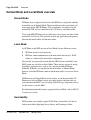
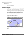
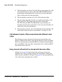
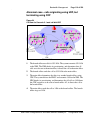
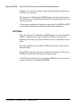
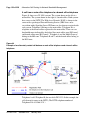
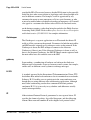
The SRG is implemented on a BCM50 platform and is connected to a
CS 1000 at the main office over a LAN or a WAN. This configuration allows
the call processing for the IP Phones at the SRG site to be centralized at the
main office. The Call Server at the main office provides the call processing
for the IP Phones in both the main office and branch offices. The SRG
provides call processing functionality to telephones in local mode and local
analog devices. The SRG also provides digital and analog trunk access to the
local Public Switched Telephone Network (PSTN).
In order for devices in the CS 1000 network to access analog devices at the
SRG or to access the PSTN at the SRG, virtual trunks are used over the LAN/
WAN.
If the main office fails to function, or if there is a network outage, the SRG
provides service to the telephones located at the branch office. This enables
the IP Phones to survive the outage between the branch office and the main
office.
The SRG is designed to work with a main office only if the main office and
the SRG use a common dialing plan. Any other configuration is not
guaranteed to work reliably. Since the Call Server and the SRG handle dialing
slightly differently, ensure that any settings you use for the main office, that
need to interact with the SRG, can be accommodated by the SRG call
processing.
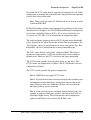
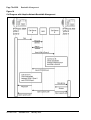
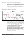
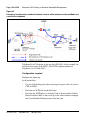
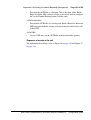
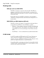
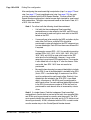
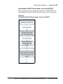
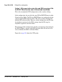
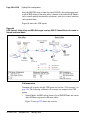
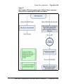
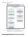
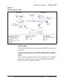
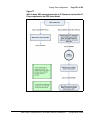
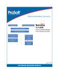
Figure 1 on page 17 shows the networking among the main office, SRG, and
IP Phones.
553-3001-207
Standard 2.00
January 2006
Overview
Page 17 of 258
Figure 1:
SRG network
Main office hardware description
The main office must be one of the following systems:
•
CS 1000S
•
CS 1000E
•
CS 1000M Cabinet
•
CS 1000M Chassis
•
CS 1000M HG
•
CS 1000M SG
•
CS 1000M MG
Note: Throughout this document, references to CS 1000 systems
encompass all CS 1000 system types.
The diagrams throughout this documentation show a CS 1000S main office.
All of the systems appearing in the list perform identical main office
functions as far as the SRG is concerned. For information about the SRG,
refer to SRG50 Configuration Guide.
Main Office Configuration for Survivable Remote Gateway 50
Configuration Guide
Page 18 of 258
Overview
Signaling Server
The Signaling Server is required at the main office only. It provides the
following functions:
•
Terminal Proxy Server (TPS)
— The TPS provides a connection from the IP Phones to the Call
Server. It also provides a connection path from a virtual trunk to the
Call Server.
•
Web server for Element Manager and Network Routing Service (NRS)
Manager
A second Signaling Server can be used to provide redundancy in the case of
failure in the primary Signaling Server at the main office.
A similar function to the Signaling Server exists at the SRG.
The Signaling Server supports both en bloc and overlap signaling. En bloc
signaling is standard. If overlap signaling is to be used, Nortel recommends
that it be installed and enabled on all Signaling Servers in the network. Failure
to do so results in delays in call completion due to overlap to en bloc
conversion.
For more information about the Signaling Server, refer to Signaling Server:
Installation and Configuration (553-3001-212). For more information about
H.323 and overlap signaling, refer to IP Peer Networking: Installation and
Configuration (553-3001-213).
Network Routing Service
•
The NRS application provides network-based routing, combining the
following into a single application:
•
H.323 Gatekeeper — provides central dialing plan management and
routing for H.323-based endpoints and gateways.
Note: NRS also contains SIP Redirect Server but SIP Trunks are not
supported on an SRG.
553-3001-207
Standard 2.00
January 2006
Overview
Page 19 of 258
•
NRS Database — stores the central dialing plan in XML format for the
H.323 Gatekeeper. The H.323 Gatekeeper accesses this common
endpoint and gateway database.
•
Network Connect Server (NCS) — used only for Media Gateway
1000B (MG 1000B), SRG, Geographic Redundancy and Virtual Office
solutions. The NCS allows the Line TPS (LTPS) to query the NRS using
the UNIStim protocol.
•
NRS Manager web interface — the NRS provides its own web
interface to configure the H.323 Gatekeeper and the NCS.
The NRS application provides routing services to H.323 devices. The H.323
Gatekeeper can be configured to support H.323 routing services. The H.323
Gatekeeper can reside on the same Signaling Server.
Each system in an IP Peer network must register to the NRS. The NRS
software identifies the IP addresses of systems based on the network-wide
numbering plan. NRS registration eliminates the need for manual
configuration of IP addresses and numbering plan information at every site.
When configuring the NRS it is necessary to enable the NCS. Ensure that the
check box “Network Connection Server enabled” is checked in the NRS
configuration window of CS 1000 Element Manager.
For information about configuring the NRS, refer to IP Peer Networking:
Installation and Configuration (553-3001-213).
Telephones
The SRG supports the following telephones:
•
IP Phone 2001
•
IP Phone 2002
•
IP Phone 2004
•
IP Phone 2007
•
IP Softphone 2050
•
Mobile Voice Client (MVC) 2050
Main Office Configuration for Survivable Remote Gateway 50
Configuration Guide
Page 20 of 258
Overview
•
Analog (500/2500-type) telephones
•
WLAN Handset 2210/2211
Note: Throughout this document, the IP Phones in this list are referred
to collectively as IP Phones.
Main office requirements
The branch office requires the following at the main office:
•
CS 1000 hardware, running Succession 3.0, CS 1000 Release 4.0, or
CS 1000 Release 4.5.
•
IP Peer H.323 Trunk (H323_VTRK) package 399. This package is
required to support H.323 functionality. Package 184 is included with
package 399.
•
The main office must have a software Service Level of 2 or higher to
work with the branch office.
•
Ensure that you have ordered enough IP user and Virtual Trunk licenses
at the main office to support the SRG50 or the capacity of your branch
office.
The main office requires the following software packages to support the
specified Basic Network features. Refer to Basic Network Features (5533001-379) for more information about these features.
•
Network Call Back Queuing (MCBQ) package 38. This package is
required for SRG IP Phones to invoke any queuing feature or ringback
when free.
•
Network Speed Call (NSC) package 39. This package is required for
SRG IP Phones to invoke the Network Speed Call feature.
The main office requires the following software packages to support the
specified ISDN Primary Rate Interface features. Refer to ISDN Primary Rate
553-3001-207
Standard 2.00
January 2006
Overview
Page 21 of 258
Interface: Features (553-3001-369) for more information about these
features.
•
Network Attendant Service (NAS) package 159. This package is
required for analog (500/2500-type) telephones in the branch office to
access attendant services when the attendant is configured on the main
office.
•
Network Message Services (NMS) package 175. This package is
required for analog (500/2500-type) telephones in the branch office to
share the voicemail system in the main office. For any configurations
using centralized CallPilot on the main office with one or more branch
offices in separate time zones, the NMS package is required at the main
office for the branch IP Phones.
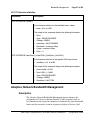
Optional features to enhance SRG functionality
•
Network Alternate Route Selection (NARS) package 58. Refer to Basic
Network Features (553-3001-379).
•
Overlap Signaling (OVLP) package 184. This package is optional; it is
required for overlap signaling. It is packaged with H.323 Virtual Trunk
(H323_VTRK) package 399 (Release 4.0 only).
•
Emergency Services Access (ESA) package 329. This package is
optional; it is required only to receive 911/ESA features in North
American and some Caribbean and Latin American (CALA) markets.
Refer to Emergency Services Access: Description and Administration
(553-3001-313).
•
Virtual Office (VIRTUAL_OFFICE) package 382. This package is
optional; it is required only for Virtual Office functionality.
•
Network Signaling (NSIG) package 37. This package is optional for
SRG IP Phones to access set-based Network Class of Service (NCOS)
features.
•
Adaptive Network Bandwidth Management package 407.
•
Alternative Call Routing for Network Bandwidth Management.
For software and hardware requirements for SRG, refer to SRG50
Configuration Guide.
Main Office Configuration for Survivable Remote Gateway 50
Configuration Guide
Page 22 of 258
Overview
Normal Mode and Local Mode overview
Normal Mode
IP Phones that are physically located at the SRG but are registered with the
main office are in Normal Mode. The main office provides centralized call
processing for the SRG IP Phones. These telephones are registered to the
main office TPS and are controlled by the Call Server at the main office.
Users of the SRG IP Phones receive the features, key layout, and tones of the
main office Call Server. This provides feature and application transparency
between the branch office and the main office.
Local Mode
An IP Phone at the SRG may be in Local Mode for two different reasons;
1
IP Phone may have just booted up.
2
IP Phone cannot communicate to the main office because of a WAN
failure or a failure of the main office components.
Devices that are physically located with the SRG and are controlled by the
SRG system are said to be in Local Mode. These devices consist of analog
telephones, analog devices, such as, fax, and may include IP Phones.
Normally IP Phones are registered to the main office, in Normal Mode;
however, when the IP Phone cannot reach the main office, it reverts to Local
Mode.
IP Phone users in Normal Mode use the feature set on the main office. IP
Phone users in Local Mode receive only those features and tones that are
provisioned on the SRG. Users of analog (500/2500-type) telephones always
use the feature set on the SRG.
For information about the features supported in Local Mode, refer to SRG50
Configuration Guide.
Survivability
SRG provides survivability against WAN failure, main office Call Server
failure, main office Signaling Server failure, and Gatekeeper failure.
553-3001-207
Standard 2.00
January 2006
Overview
Page 23 of 258
SRG supports the Geographic Redundancy feature. For further information
about Geographic Redundancy, see Communication Server 1000: System
Redundancy (553-3001-307).
In the event of a WAN failure, the SRG IP Phones lose communication with
the main office. This causes the SRG IP Phones to reset and register with the
SRG. The IP Phones then operate in Local Mode, providing services based on
a limited SRG feature set, which has significant differences from the CS 1000
software. For further information about services and features supported on
the SRG, refer to SRG50 Configuration Guide.
If the main office Call Server fails and call processing services are provided
by an Alternate Call Server, the SRG IP Phones reset and reregister with the
Alternate Call Server and receive call processing services from it. If no
Alternate Call Server is available, the SRG IP Phones go to Local Mode while
the SRG attempts to find an Alternate Call Server by way of the NCS.
If the main office Signaling Server fails and an Alternate Signaling Server is
available, the SRG IP Phones reset and reregister with the SRG. The SRG will
then query the NCS for the Alternate Signaling Server’s IP address. The SRG
will redirect the IP Phone to the Alternate Signaling Server and continue to
receive call processing services from the main office Call Server. If no
Alternate Signaling Server is available, the SRG IP Phones reset and register
with the SRG in Local Mode.
When an IP Phone at the SRG first boots up, it attempts to communicate with
the SRG. After it establishes communications with the SRG, the SRG
redirects it to the main office. When the SRG IP Phone attempts to register
with the main office, the SRG first queries the Primary NRS (NCS) for the
main office Virtual Trunk node IP address to redirect the IP Phone. If the
Primary NRS (NCS) is down or unreachable, the SRG queries the
Alternate NRS (H.323 Gatekeeper), if one is specified. If it receives a
positive response, the SRG IP Phone is redirected to the specified main office.
Otherwise, if neither a Primary or an Alternate NRS (H.323 Gatekeeper) is
available, the SRG IP Phone remains in Local Mode, and receives call
processing services from the SRG until communication can be reestablished.
SRG IP Phones in Normal Mode remain registered with the main office if the
Primary NRS fails and no Alternate NRS is available. They can call any main
office telephone or IP Phones in Normal Mode in other branch offices.
Main Office Configuration for Survivable Remote Gateway 50
Configuration Guide
Page 24 of 258
Overview
However, they cannot call any SRG analog (500/2500-type) telephones or
any external numbers through the SRG trunks because the Virtual Trunks are
not available. (SRG analog [500/2500-type] telephones are accessible if
alternate routing is available through the PSTN.)
Recovery to Normal Mode
If an IP Phone is in Local Mode due to WAN failure or main office
component failure, the SRG tries to communicate with the main office TPS
at regular intervals. Once communication is established with the main office
call server, the idle SRG IP Phones are automatically redirected and
reregistered to the main office. IP Phones that were busy at the time
communication was reestablished complete the call in Local Mode, and then
reregister with the main office after the call is complete.
Local Mode operation
When an SRG IP Phone is in Local Mode, the user has full access to the
services configured at the SRG (analog devices or analog or digital trunks)
and to other IP Phones registered to the SRG. In Local Mode, the IP Phones
can make local calls to other IP Phones and other analog (500/2500-type)
telephones at the branch office. They can also be used to make outgoing
PSTN calls and receive incoming calls as usual. SRG IP Phones can access
the main office IP Phones or other branches by routing through the local
PSTN.
IMPORTANT!
When a telephone or trunk in the main office calls an SRG IP Phone that
has switched to Local Mode due to WAN failure, the call is treated
according to the main office call redirection configuration (such as
forwarding to voicemail or continuous ringback).
Testing the telephone in Local Mode
From Normal Mode, the branch user has the option of going to Local Mode
manually by resetting the telephone or using Test Local Mode. The test can
be performed by the user at any time and does not require a password. This
test is invoked from the IP Phone.
553-3001-207
Standard 2.00
January 2006
Overview
Page 25 of 258
Nortel recommends testing Local Mode operation after changing the
provisioning for a telephone on the SRG.
To ensure that users do not forget to resume Normal Mode operation, the
SRG redirects the telephone to the main office to return the telephone to
Normal mode. This occurs if the telephone remains registered to the SRG in
Test Local Mode for ten minutes (default setting). Alternatively, the user can
press the Quit key
from the set to return to Normal Mode.
X
For further information about Local Mode functionality for SRG, refer to
SRG50 Configuration Guide.
Virtual Trunks
In order for endpoints in the CS1000 network to access endpoints in local
mode at the SRG or to access the PSTN at the SRG, Virtual Trunks are used
over the LAN/WAN.
Virtual Trunks are software components that provide the trunking features of
the Meridian Customer-Defined Network (MCDN) feature set. Access to
PSTN digital or analog trunks at the branch office occurs through the MCDN
Virtual Trunk.
For more information about Virtual Trunks, refer to IP Peer Networking:
Installation and Configuration (553-3001-213).
Note: Virtual Trunks are sometimes referred to as H.323 IP Peer Trunks.
In the SRG50 Configuration Guide, Virtual Trunks are referred to as IP
Trunks.
IP Phone calls
When an IP Phone calls another IP Phone, each telephone receives the
address of the other to exchange media directly between the telephones.
When in Normal Mode, an SRG IP Phone calling a main office IP Phone does
not require any trunking to set up the call. However, LAN/WAN bandwidth
is used to provide a media path for the call. For more information on Direct
IP media path functionality, see IP Peer Networking: Installation and
Configuration (553-3001-213).
Main Office Configuration for Survivable Remote Gateway 50
Configuration Guide
Page 26 of 258
Overview
Bandwidth Management Overview
For a complete overview of Bandwidth Management, refer to the Converging
the Data Network with VoIP (553-3001-160), and for details on
configuration, refer to “Bandwidth Management” on page 49.
Network Bandwidth Management
Network Bandwidth Management allows for a limit to be placed on the
amount of interzone bandwidth allowed between IP Phones in Normal Mode
at the SRG and the rest of the CS 1000 network.
As well, it allows for the selection of interzone bandwidth codecs for calls
between the IP Phones in Normal Mode and the rest of the CS 1000 network.
Adaptive Network Bandwidth Management
Adaptive Network Bandwidth Management allows the system to dynamically
react to Quality of Service (QoS) degradation and take corrective action.
Network Bandwidth Management Zones
A zone is a collection of IP Phones that:
•
share similar IP bandwidth restrictions
•
are geographically close to one another
•
are all in the same time zone
•
are all in the same PSTN dialing plan
The Network Bandwidth Management Zone is made up of the VPNI and the
zone. The VPNI of the main office and all the SRG associated with it must be
the same.
Each SRG must have its own unique zone number and configured in the main
office Call Server and the SRG.
Note: Throughout this document, the term “zone” is defined as a
Bandwidth Management Zone, not an NRS (H.323 Gatekeeper) Zone.
Refer to “Bandwidth Management” on page 49.
553-3001-207
Standard 2.00
January 2006
Overview
Page 27 of 258
Miscellaneous items
Time of Day
Because the SRG IP Phones, in Normal Mode, receive their clock information
from the main office, which may be located in a different time zone, the main
office must be able to provide a different time of day for these phones.
The time zone of the SRG is configured with the SRG zone at the main office.
The time zone adjusts the main office time for display at the SRG. SRG
telephones then display the correct time of the SRG, rather than that of the
main office. For any configurations using centralized Call Pilot on the main
office with one or more branch offices in separate time zones, the NMS
package is required at the main office for the branch IP Phones.
SRG IP Phone to local PSTN calls
When an SRG IP Phone in Normal Mode dials a local PSTN number, the call
is processed by the main office Call Server. The dialed digits are modified
according to the dialing plan information configured in the zone for the SRG
IP Phone.
The call is configured to be routed over the Virtual Trunk to the branch office.
The SRG then tandems the call to the local PSTN.
Likewise, long distance calls can also be configured.
IMPORTANT!
If you use one Access Code for both local and long distance calls, and
that Access Code is associated with a branch office zone, all calls (local
and long distance) are routed through the SRG.
IP Phone to analog (500/2500-type) telephone calls
When an IP Phone in Normal Mode at the SRG calls an analog (500/2500type) telephone of the same SRG, the call is processed at the main office Call
Server. A Virtual Trunk route is selected according to the digits dialed. The
call is routed over a Virtual Trunk to the branch office. The SRG processes
the incoming Virtual Trunk call and terminates it to the local analog (500/
Main Office Configuration for Survivable Remote Gateway 50
Configuration Guide
Page 28 of 258
Overview
2500-type) telephone. Since this is a call between IP and circuit-switched
devices, a DSP resource on a Media Card is allocated and connected to the
analog (500/2500-type) telephone. The IP address of the DSP resource is
returned to the main office Call Server so a direct media path between the
IP Phone and the DSP resource can be set up when the call is established.
Refer to IP Peer Networking: Installation and Configuration (553-3001-213)
for details.
Conference calls
When an SRG user initiates a conference call, the conference facilities of the
main office are used. This means that in a conference among three SRG users,
the LAN/WAN bandwidth of three media paths is used. The calls are
controlled by the main office, except in Local Mode. In Local Mode, SRG
users do not have access to conferencing.
553-3001-207
Standard 2.00
January 2006
Overview
Page 29 of 258
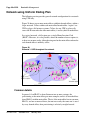
Networking consideration
A fault condition can occur if IP Phones use a different route to the main
office than that used by the SRG.
CAUTION — Service Interruption
If the network is planned so that IP Phones use a different
route to the main office than that used by the SRG, a fault
condition can occur. When the SRG can ping the main
office but the IP Phone cannot ping the main office due to
a network outage, an IP Phone registration can force the
telephone into a cycle of registering locally, being
redirected to the main office, rebooting, and then
registering locally again. When this cycle occurs, further
diagnose the network outage.
Capacity
Each CS 1000 main office can support up to 255 branch offices, which can be
made up of any combination of SRGs and MG 1000Bs. SRG50 supports up
to 32 IP Phone users. However, since all IP Phones register with the main
office, the governing factor is the maximum number of IP Phones that can be
supported at the main office. This means the total number of IP Phones in all
offices can be no greater than the capacity of the main office. Refer to one of
the following documents to determine the total number of phones your system
can support:
•
Communication Server 1000S: Planning and Engineering (553-3031120)
•
Communication Server 1000E: Planning and Engineering (553-3041120)
•
Communication Server 1000M and Meridian 1: Large System Planning
and Engineering (553-3021-120)
•
Communication Server 1000M and Meridian 1: Small System Planning
and Engineering (553-3011-120).
Main Office Configuration for Survivable Remote Gateway 50
Configuration Guide
Page 30 of 258
Overview
Virtual Trunks capacity
The SRG capacity to support a number of simultaneous calls depends on the
specific codec type used.
In Normal Mode, the codec selection used is controlled by specific
programming of the CS 1000. In this case: SRG 505 supports up to a
maximum of 15 Virtual trunks unless both the intrazone and interzone codecs
are configured as Best Quality (G.711), in which case the maximum number
of Virtual Trunks would be 24.
In Local Mode, if the WAN has failed, there are no longer any Virtual Trunks
available between the SRG and CS 1000. However, the SRG will continue to
convert calls from IP terminals for communication through the PSTN. Nortel
recommends you use G.711 codec. In this case, if G.711 is used, the number
of simultaneous calls from IP terminals to the PSTN supportable is a
maximum of 24.
Branch office dialing plan
Since IP Phone users can be located at a branch office equipped with an SRG,
the routing of calls to the local gateway is important (especially when toll
charges apply to calls made from the central Call Server that controls the
telephone). The administrator can configure digit manipulation through zone
attributes for IP Phones to select a main office or branch office that provides
PSTN access local to the destination of the call.
Calls from the PSTN to users within the network can be routed with the
various ESN numbering plan configurations.
To access local PSTN resources, outgoing calls can be routed using ESN as
well as zone parameters that enable digit insertion. The zone parameters force
calls made by an SRG user to be routed to the desired local PSTN facilities.
Note: Outgoing calls can include local and, optionally, long distance
calls.
Nortel recommends that the Branch User ID (BUID) be the same at the
branch office as the DN at the main office. A BUID has a maximum of 15
digits. Under the recommended Coordinated Dialing Plan (CDP), the BUID
553-3001-207
Standard 2.00
January 2006
Overview
Page 31 of 258
can be an extension (for example, 4567). Under the Uniform Dialing Plan
(UDP), it is the user’s main office DN, the Location Code (LOC), plus the
Access Code (for example, 6 343-5555).
Note: The main office DN must be an ESN compliant DN. See “ESN
Access Codes” on page 31.
For more information about dialing plans and configuration, see “Dialing
Plan configuration” on page 167. For more information about the branch
office dialing plan, refer to SRG50 Configuration Guide.
ESN Access Codes
ESN data is configured with two Access Codes, called AC1 and AC2. AC1
normally applies to long distance calls, whether placed on or off the
customer’s private network (for example, dialing “6”). AC2 normally applies
to local calls (for example, “9”). For more information, refer to Electronic
Switched Network: Signaling and Transmission Guidelines (553-3001-180).
Music on Hold
For SRG users in Normal Mode, the main office provides music to the user if
Music on Hold is provisioned. The use of the G.729A/AB codec between the
main office and the branch office may impact the music quality.
Note: G.723 codec is not supported on SRG50.
Main Office Configuration for Survivable Remote Gateway 50
Configuration Guide
Page 32 of 258
Overview
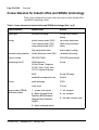
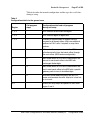
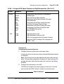
Cross reference for branch office and SRG50 terminology
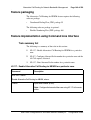
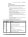
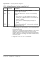
Table 1 lists configuration-related terms and contexts where branch office
and SRG50 terminology differ.
Table 1: Cross reference for branch office and SRG50 terminology (Part 1 of 2)
Term or context
Branch office
SRG50
dialing plan
on-net/off-net dialing
Private/Public network
dialing
routing
distant steering codes (DSC),
Trunk steering codes (TSC),
Local steering codes (LSC)
call routing, destination
codes, line pool access
codes
Digit manipulation table
dial-out digits (routing)
alternate routing selection
Facility Restriction Level (FRL)
scheduled call routing
Type of number
CDP/UDP/TNDN
CDP/UDP/no equivalent
Numbering Plan ID
ISDN/Telephony
(E.164),Private, Telephony
(E.163), Telex, (F.69), Data
(X.121), National Standard
Private
BUID
Private DN length
bandwidth management zone
Zone ID
public exchange
PSTN
virtual trunk
IP trunk
7 = system trunk access
7 = not assigned
8 = Basic Alternate Route
Selection (BARS)/Network
Alternate Route Selection
(NARS)
8 = not assigned
Trunks
access codes (SRG50:
destination codes)
9 = public exchange access
553-3001-207
Standard 2.00
January 2006
9 = line pool A access code
Overview
Page 33 of 258
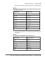
Table 1: Cross reference for branch office and SRG50 terminology (Part 2 of 2)
Term or context
Branch office
SRG50
Network Class of Service
(NCOS)
telephone numbers
(internal, not PSTN)
TN
DN, MOTN
Main Office Configuration for Survivable Remote Gateway 50
Configuration Guide
Page 34 of 258
553-3001-207
Overview
Standard 2.00
January 2006
48
Page 35 of 258
Setting up the main office
Contents
This section contains information on the following topics:
Introduction . . . . . . . . . . . . . . . . . . . . . . . . . . . . . . . . . . . . . . . . . . . . . .
35
SRG information required by the main office. . . . . . . . . . . . . . . . . . . .
36
Main office information required by the SRG . . . . . . . . . . . . . . . . . . .
37
Zone parameters . . . . . . . . . . . . . . . . . . . . . . . . . . . . . . . . . . . . . . . . . .
39
Branch office IP Phone configuration at the main office . . . . . . . . . . .
46
Introduction
This section describes the following information required to configure the
main office:
•
SRG information required by the main office
•
Main office information required by the SRG
•
Zone parameters
•
IP Phone passwords and parameters
•
Branch office IP Phone configuration
Main Office Configuration for Survivable Remote Gateway 50
Configuration Guide
Page 36 of 258
Setting up the main office
For more information on main office configuration, refer to IP Peer
Networking: Installation and Configuration (553-3001-213).
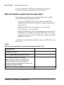
SRG information required by the main office
The main office administrator must gather information about the SRG
system. The following information is required:
•
an inventory of IP Phones that will be installed on the SRG so the
administrator knows what type of telephone to assign to each main office
terminal record
•
information which allows the administrator to create an NRS
(H.323 Gatekeeper) entry for the SRG
•
if using advanced routing, such as tandem dialing between systems, local
PSTN number for the SRG and the internal SRG routing codes that will
allow the main office to connect to the SRG and to tandem over the SRG
PSTN lines, is required.
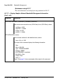
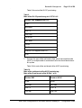
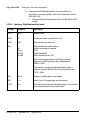
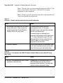
Use Table 2 to record the information before setting up the SRG on the main
office server.
Table 2:
SRG information required for the main office configuration (Part 1 of 2)
SRG parameters
SRG public IP address
H.323 ID (gatekeeper identification of the SRG)
List of types and number of IP Phones
Note: Telephone types are hard-coded to the
Terminal Numbers (TNs) and the main office.
Therefore, install the same type of IP Phones to the
coordinating record on the SRG.
PSTN number to dial into the SRG (in local mode)
553-3001-207
Standard 2.00
January 2006
Setting up the main office
Page 37 of 258
Table 2:
SRG information required for the main office configuration (Part 2 of 2)
SRG parameters
Destination codes (steering codes) to route the main
office calls to the SRG and out through the SRG
PSTN lines
IP Ports that affect SRG traffic with the main office and
have been assigned firewall filters
For further information on port configuration, refer to
Converging the Data Network with VoIP (553-3001160) or SRG50 Configuration Guide.
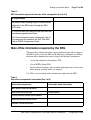
Main office information required by the SRG
The main office administrator must supply numerous main office settings to
the SRG installer so that the SRG can be efficiently configured. In addition,
the main office administrator needs to supply the following information:
•
a list of the terminal record numbers (TNs)
•
a list of BUIDs (Prime DNs)
•
if using advanced routing, such as tandem dialing between systems, main
office routing (steering) codes, are required
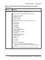
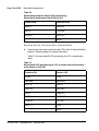
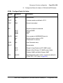
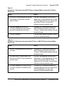
Use Table 3 to record main office information required by the SRG.
Table 3
Main office interoperation information (Part 1 of 3)
Main office components
Information about this system
Main office IP network information:
Main office call server type
S1000 (default)
Primary network connect server address
Alternate network connect server
Network Connect server port
Main Office Configuration for Survivable Remote Gateway 50
Configuration Guide
Page 38 of 258
Setting up the main office
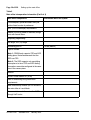
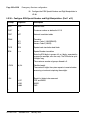
Table 3
Main office interoperation information (Part 2 of 3)
Main office components
Information about this system
Trunk/telephony preferred codecs and jitter
buffers listed in order of preference
NRS (H.323 Gatekeeper) requirements
Indicate if the SRG needs to manually assign
ports with firewall filters.
Telephony programming:
DN length, DN (TN) range
Numbering plan ID
Private (default)
Type of number
Note 1: SRG50 only supports CDP and UDP
dialing plans. Nortel recommends that the
SRG use CDP.
Note 2: The SRG supports only one dialing
plan option at a time. CDP and UDP dialing
plan options cannot be configured at the same
time in the same system.
Node ID
Virtual Private Network ID (VPNI)
Zone ID and dialing string information
requirements
Main office dial-up number (for PSTN calls to
the main office in Local Mode.
Access code to reach the main office PSTN
through VoIP trunks
553-3001-207
Standard 2.00
January 2006
Setting up the main office
Page 39 of 258
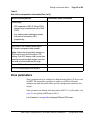
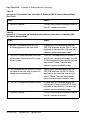
Table 3
Main office interoperation information (Part 3 of 3)
Main office components
Information about this system
Zone dialing:
• ZDP appended to SRG IP Phone PSTN
dialing strings to redirect the call to SRG
PSTN
• Any steering codes (destination codes)
that must be mirrored by SRG
programming
IP Phone configuration:
MOTN/BUID list, including which type of
IP Phone is assigned to each number
Note: Make note of the leading number, as
SRG uses this as the DN range for CDP
dialing. If the DCP access code is more than
one digit, the second digit number must also
be used to further define the DN range.
Current IP Phone firmware version
Is a VLAN configured on the network?
Zone parameters
Zone parameters must be configured at both the main office Call Server and
the SRG. The main office procedure is similar to an IP Peer Network
configuration with the branch office-specific configuration outlined in this
chapter.
Zone parameters are defined at the main office in LD 117 (see Procedure 1 on
page 40) and applied to IP Phones in LD 11.
Use Procedure 1 on page 40 to configure ESN and SRG zones.
Main Office Configuration for Survivable Remote Gateway 50
Configuration Guide
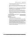
Page 40 of 258
Setting up the main office
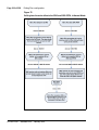
Procedure 1
Configuring ESN and SRG zones
IMPORTANT!
Before and after an upgrade, perform a data dump (using LD 43 EDD or
through Element Manager) on the Call Server or SSC to back up
existing data.
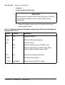
1
Configure the Home Location Code (HLOC) and the Virtual Private
Network Identifier (VPNI).
LD 15 – Configure Customer Data Home Location Code and Virtual Private Network
Identifier (Part 1 of 2)
Prompt
Response
Description
REQ:
CHG
Change existing data.
TYPE:
NET
ISDN and ESN Networking options
CUST
Customer number
0-99
Range for Large System and CS 1000E system
0-31
Range for Small System, CS 1000S system, Media
Gateway 1000B, and Media Gateway 1000T
CLID
YES
Allow Calling Line Identification option
- ENTRY
xx
CLID entry to be configured
- - HLOC
100-9999999
Home Location code (ESN) (3-7 digits)
...
553-3001-207
Standard 2.00
January 2006
Setting up the main office
Page 41 of 258
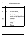
LD 15 – Configure Customer Data Home Location Code and Virtual Private Network
Identifier (Part 2 of 2)
Prompt
Response
Description
ISDN
YES
Integrated Services Digital Network
-VPNI
(0)-16383
Virtual Private Network Identifier for Bandwidth
Management feature
X = Disables feature
1-16383 = Enables feature
<cr> = No Change
2
Configure the zone properties for IP Telephony bandwidth management.
Use LD 117 or Element Manager. Refer to IP Peer Networking:
Installation and Configuration (553-3001-213).
Main Office Configuration for Survivable Remote Gateway 50
Configuration Guide
Page 42 of 258
Setting up the main office
Note: The branch office zone number and zone bandwidth management
parameters at the main office must match the corresponding branch office
zone number and zone bandwidth management parameters at the branch
office.
IMPORTANT!
Zone 0, the default zone, must not be configured as a branch office
zone. Network Bandwidth Management does not support zone 0. If
zone 0 is configured as an branch office zone, the Bandwidth
Management feature is not activated.
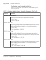
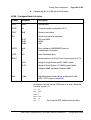
3
Define the zone parameters for the branch office. Use LD 117 or Element
Manager. Refer to IP Peer Networking: Installation and Configuration
(553-3001-213).
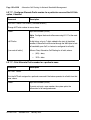
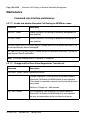
LD 117 – Define zone parameters for the branch office.
Command
Description
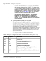
CHG ZBRN <Zone> <yes|no>
Define a zone as a branch office zone.
CHG ZDST <Zone> <yes|no> <StartMonth> <StartWeek> <StartDay> <StartHour>
<EndMonth> <EndWeek> <EndDay> <EndHour>
If the branch office observes Daylight Savings Time (DST), these
parameters specify the start and end of DST. During DST, the clock
automatically advances one hour forward.
CHG ZTDF <Zone> <TimeDifferencefromMainOffice>
Specified in minutes, the time difference between main office and branch
office when both are not in DST.
CHG ZDES <Zone> <ZoneDescription
A name to render data display more meaningful.
553-3001-207
Standard 2.00
January 2006
Setting up the main office
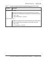
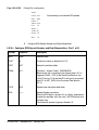
4
Page 43 of 258
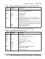
Enable the features for the branch office zone in LD 11.
LD 117 – Enable features for an SRG zone.
Command
Description
ENL ZBR <zone> ALL
Enables features for branch office <zone>.
End of Procedure
Configuring zone parameters using
CS 1000 Element Manager
Use Element Manager to configure the branch office specific zone properties
and time difference.
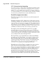
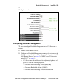
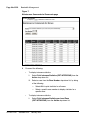
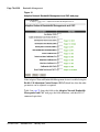
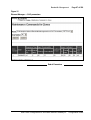
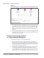
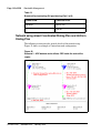
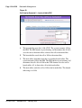
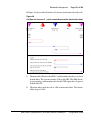
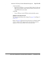
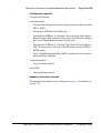
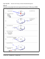
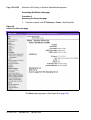
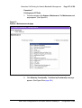
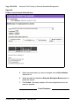
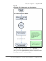
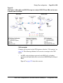
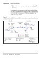
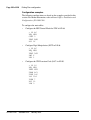
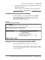
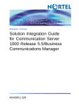
1
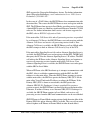
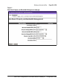
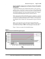
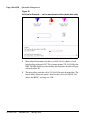
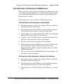
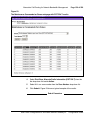
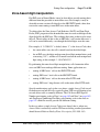
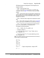
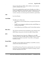
Select IP Telephony > Zones in Element Manager navigator.
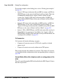
The Zones window opens (Figure 2 on page 44). The zone list is the main
window used for zone configuration.
Main Office Configuration for Survivable Remote Gateway 50
Configuration Guide
Page 44 of 258
Setting up the main office
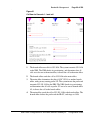
Figure 2
Zone List web page
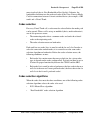
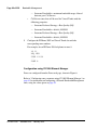
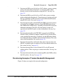
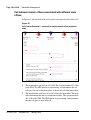
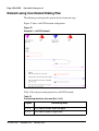
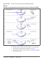
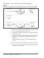
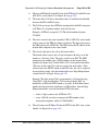
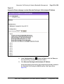
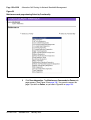
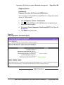
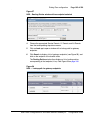
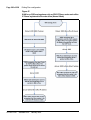
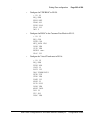
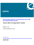
2
553-3001-207
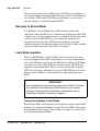
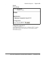
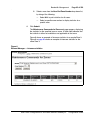
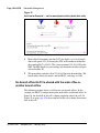
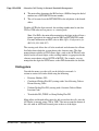
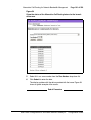
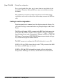
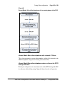
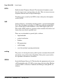
Select the zone to be configured and configure the following properties.
•
Basic Property and Bandwidth Management (see Figure 3 on
page 45)
•
Dialing Plan and Access Codes (see Figure 61 on page 192)
•
Emergency Service Information (see Figure 78 on page 239)
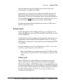
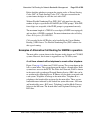
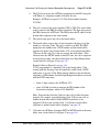
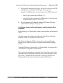
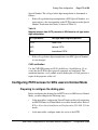
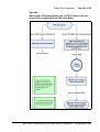
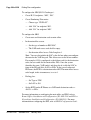
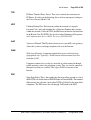
•
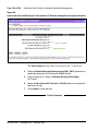
Time Difference and Daylight Saving Time Property (see Figure 4 on
page 46)
Standard 2.00
January 2006
Setting up the main office
Page 45 of 258
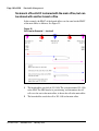
Figure 3
Zone Basic Property and Bandwidth Management web page
Main Office Configuration for Survivable Remote Gateway 50
Configuration Guide
Page 46 of 258
Setting up the main office
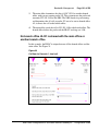
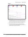
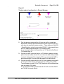
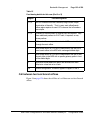
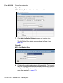
Figure 4
Zone Time Difference and Time web page
Zone parameters must be configured on the main office and the branch office.
For information on configuring zones, refer to “Bandwidth Management” on
page 49.
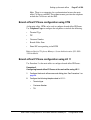
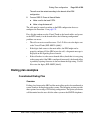
Branch office IP Phone configuration at the main office
After the branch office zones and passwords are provisioned, provision the
branch office IP Phones at the main office. These can be provisioned using
OTM (see “Branch office IP Phone configuration using OTM” on page 47)
or LD 11 (see Procedure 2).
553-3001-207
Standard 2.00
January 2006
Setting up the main office
Page 47 of 258
Note: There is no automatic data synchronization between the main
office Call Server and SRG. The technician must provision the telephone
on both the Call Server and the SRG.
Branch office IP Phone configuration using OTM
At the main office, OTM can be used to configure branch office IP Phones.
Use Telephone Pages to configure the telephones to include the following:
•
Terminal Type
•
TN
•
Customer Number
•
Branch Office Zone
•
Prime DN corresponding to the BUID
Refer to Optivity Telephony Manager: System Administration (553-3001330) for details.
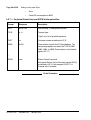
Branch office IP Phone configuration using LD 11
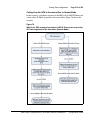
Use Procedure 2 at the main office to configure branch office IP Phones.
Procedure 2
Configuring branch office IP Phones at the main office using LD 11
1
Configure the branch office zones and dialing plan. See Procedure 1 on
page 40.
2
Configure the following telephone data in LD 11:
•
Terminal type
•
Customer Number
•
TN
Main Office Configuration for Survivable Remote Gateway 50
Configuration Guide
Page 48 of 258
Setting up the main office
•
Zone
•
Prime DN to correspond to BUID
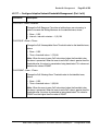
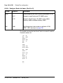
LD 11 – Provision Branch User and SCPW at the main office
Prompt
Response
Description
REQ:
NEW CHG
Add new data, or change existing data.
TYPE:
a...a
Terminal type.
Type ? for a list of possible responses.
CUST
xx
Customer number as defined in LD 15.
ZONE
0-255
Zone number to which the IP Phone belongs. The
zone prompt applies only when the TYPE is i2001,
i2002, i2004, or i2050. Zone number is not checked
against LD 117.
xxxx
Station Control Password
Must equal Station Control Password Length (SCPL)
as defined in LD 15. Not prompted if SCPL = 0.
Precede with X to delete.
...
SCPW
End of Procedure
553-3001-207
Standard 2.00
January 2006
126
Page 49 of 258
Bandwidth Management
Contents
This section contains information on the following topics:
Introduction . . . . . . . . . . . . . . . . . . . . . . . . . . . . . . . . . . . . . . . . . . . . . .
50
Codec negotiation . . . . . . . . . . . . . . . . . . . . . . . . . . . . . . . . . . . . . . . . .
Codec selection. . . . . . . . . . . . . . . . . . . . . . . . . . . . . . . . . . . . . . . . .
Codec selection algorithms. . . . . . . . . . . . . . . . . . . . . . . . . . . . . . . .
50
53
53
Interoperability between CS 1000 and SRG . . . . . . . . . . . . . . . . . . . . .
Zones . . . . . . . . . . . . . . . . . . . . . . . . . . . . . . . . . . . . . . . . . . . . . . . .
Configuration rules. . . . . . . . . . . . . . . . . . . . . . . . . . . . . . . . . . . . . .
Network Planning. . . . . . . . . . . . . . . . . . . . . . . . . . . . . . . . . . . . . . .
Enabling codecs . . . . . . . . . . . . . . . . . . . . . . . . . . . . . . . . . . . . . . . .
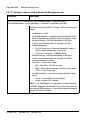
Configuring Bandwidth Management . . . . . . . . . . . . . . . . . . . . . . .
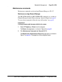
Maintenance commands . . . . . . . . . . . . . . . . . . . . . . . . . . . . . . . . . .
56
57
57
57
58
59
63
Adaptive Network Bandwidth Management. . . . . . . . . . . . . . . . . . . . .
Description . . . . . . . . . . . . . . . . . . . . . . . . . . . . . . . . . . . . . . . . . . . .
Feature packaging. . . . . . . . . . . . . . . . . . . . . . . . . . . . . . . . . . . . . . .
Configuration rules. . . . . . . . . . . . . . . . . . . . . . . . . . . . . . . . . . . . . .
Configuring Adaptive Network Bandwidth Management . . . . . . . .
Maintenance commands . . . . . . . . . . . . . . . . . . . . . . . . . . . . . . . . . .
67
67
75
75
76
85
Tandem Bandwidth Management overview . . . . . . . . . . . . . . . . . . . . .
93
Dialing Plan Overview . . . . . . . . . . . . . . . . . . . . . . . . . . . . . . . . . . . . .
94
Network using Uniform Dialing Plan . . . . . . . . . . . . . . . . . . . . . . . . . .
96
Network using Coordinated Dialing Plan . . . . . . . . . . . . . . . . . . . . . . .
122
Main Office Configuration for Survivable Remote Gateway 50
Configuration Guide
Page 50 of 258
Bandwidth Management
Introduction
CS 1000 supports Bandwidth Management on a network-wide basis so that
voice quality can be managed between multiple Call Servers.
Bandwidth management allows for codec selection and bandwidth limitations
to be placed on calls, depending on whether the calls are intrazone or
interzone.
Adaptive Network Bandwidth Management is an enhancement of Bandwidth
Management in which Quality of Service (QoS) metrics are used to
automatically lower available bandwidth.
IMPORTANT!
Once all bandwidth is used, any additional calls are blocked or rerouted.
Keep this in mind when designing and implementing Network Bandwidth
Management.
Codec negotiation
Codec refers to the voice coding and compression algorithm used by DSPs.
Each codec has different QoS and compression properties.
IP Peer Networking supports the per-call selection of codec standards, based
on the type of call (interzone or intrazone). IP Peer Networking supports the
following codecs (with supported payload sizes in parentheses, with the
default value in bold):
•
G.711 A/mu-law (10 ms, 20 ms, and 30 ms)
•
G.729 A (10 ms, 20 ms, 30 ms, 40 ms, and 50 ms)
•
G.729 AB (10 ms, 20 ms, 30 ms, 40 ms, and 50 ms)
•
G.723.1 (30 ms) (though it can limit the number of DSP channels
available)
•
T.38 for fax
Note: The G.XXX series of codecs are standards defined by the
International Telecommunications Union (ITU).
553-3001-207
Standard 2.00
January 2006
Bandwidth Management
Page 51 of 258
By default, the G.711 codec must be supported at both ends of a call. Codec
configuration is performed for each node and is independent of the signaling
gateway that is used on the node.
Note: The payload size on the CS 1000 must be set to 30 msec in order
to work with the SRG.
IP Peer Networking performs codec negotiation by providing a list of codecs
that the devices can support. Use CS 1000 Element Manager to configure the
list of codec capabilities. Refer to IP Peer Networking: Installation and
Configuration (553-3001-213) for instructions on configuring codecs.
The codec preference sequence sent over H.323 depends on the bandwidth
policy selected for the Virtual Trunk zone and the involved telephones. For
“Best Quality”, the list is sorted from best to worst voice quality. For “Best
Bandwidth”, the list is sorted from best to worst bandwidth usage.
The G.711 codec delivers “toll quality” audio at 64 kbit/s. This codec is
optimal for speech quality, as it has the smallest delay and is resilient to
channel errors. However, the G.711 codec uses the largest bandwidth.
The G.729A codec provides near toll quality voice at a low delay. The
G.729A codec uses compression at 8 kbit/s. The G.729AB codec also uses
compression at 8 kbit/s.
The G.723.1 codec provides the greatest compression.
Note 1: SRG50 does not support G.723 codec.
Note 2: Payload default values need to be changed if the customer wants
to communicate with a third-party gateway that does not support the
above default payload sizes. Otherwise, IP Peer calls to or from the
third-party gateway are not successful.
Note 3: If the payload sizes are set higher than the default values (for
example, to support a third-party gateway), then the local IP calls are
affected by higher latency. This is because the codec configuration
applies to both IP Peer calls and local IP (IP Line) calls.
Main Office Configuration for Survivable Remote Gateway 50
Configuration Guide
Page 52 of 258
Bandwidth Management
G.711 A-law and mu-law interworking
In case the far end uses a different Pulse Code Modulation (PCM) encoding
law for its G.711 codec, systems that are configured as G.711 A-law also
include G.711 mu-law on their codec preferences list. Systems configured as
G.711 mu-law include G.711 A-law as their last choice. Therefore, encoding
law conversion is performed between systems with different laws.
Bandwidth management and codecs
Bandwidth management defines which codecs are used for intrazone calls
and interzone calls.
Bandwidth management enables administrators to define codec preferences
for IP Phone to IP Phone calls controlled by the same CS 1000 system in the
same zone. These calls are known as intrazone calls. This is different than the
codec preferences for calls between an IP Phone on the CS 1000 system to a
Virtual Trunk (potentially an IP Phone on another CS 1000 system) or calls
to IP Phones in another zone. These calls are known as interzone calls.
For example, you may prefer high quality speech (G.711) over high
bandwidth within one system, and lower quality speech (G.729AB) over
lower bandwidth to a Virtual Trunk. Such a mechanism can be useful when a
system is on the same LAN as the IP Phones it controls, but the other systems
are on a different LAN (connected through a WAN).
The Virtual Trunks’ usage of bandwidth zones is different than IP Phone
bandwidth usage. For Virtual Trunks, a zone number is configured in the
Route Data Block (RDB) (LD 16). The zone number determines codec
selection for interzone and intrazone calls (that is, Best Bandwidth or Best
Quality). Refer to IP Peer Networking: Installation and Configuration
(553-3001-213) for information on configuring the RDB zone.
Bandwidth usage for Virtual Trunks is accumulated in its zone in order to
block calls that exceed the bandwidth availability in a specific zone.
However, the amount of bandwidth that is required to complete a given call
is not known until both call endpoints have negotiated which codec to use.
The bandwidth used for calculating the usage of a Virtual Trunk call is
determined by the preferred codec of the device that connects to the Virtual
Trunk. If the device is an IP Phone, the bandwidth calculations use the
preferred codec of the IP Phone, based on the codec policy defined for the
553-3001-207
Standard 2.00
January 2006
Bandwidth Management
Page 53 of 258
zones involved (that is, Best Bandwidth or Best Quality). Likewise, the
bandwidth calculations use the preferred codec of the Voice Gateway Media
Card for connections between a circuit-switched device (for example, a PRI
trunk) and a Virtual Trunk.
Codec selection
For every Virtual Trunk call, a codec must be selected before the media path
can be opened. When a call is set up or modified (that is, media redirection),
one of two processes occurs:
•
The terminating node selects a common codec and sends the selected
codec to the originating node.
•
The codec selection occurs on both nodes.
Each node has two codec lists: its own list and the far end’s list. In order to
select the same codec on both nodes, it is essential to use the same codec
selection algorithm on both nodes. Before the codec selection occurs, the
following conditions are met:
•
Each codec list contains more than one payload size for a given codec
type (it depends on the codec configuration). Payload size must be set to
30 msec for proper functionality between the CS1000 and the SRG.
•
Each codec list is sorted by order of preference (the first codec in the near
end’s list is the near end’s most preferred codec, the first codec in the far
end’s list is the far end’s preferred codec).
Codec selection algorithms
When the codec lists meet the above conditions, one of the following codec
selection algorithms selects the codec to be used:
•
H.323 Master/Slave algorithm
•
“Best Bandwidth” codec selection algorithm
Main Office Configuration for Survivable Remote Gateway 50
Configuration Guide
Page 54 of 258
Bandwidth Management
H.323 Master/Slave algorithm
In the case of a Virtual Trunk call between Nortel and third-party equipment,
the H.323 Master/Slave algorithm is used.
The codec selection algorithm proposed by the H.323 standard involves a
Master/Slave negotiation. This is initiated each time two nodes exchange
their capabilities (TCS message). The Master/Slave information decides that
one node is Master and the other node is Slave. The outcome of the Master/
Slave negotiation is not known in advance; it is a random result. One node
could be Master then Slave (or vice versa) during the same call.
Algorithm details
The H.323 Master/Slave algorithm operates in the following manner:
•
The Master node uses its own codec list as the preferred one and finds a
common codec in the far end’s list. In other words, the Master gets the
first codec in its list (for example, C1), checks in the far end’s list if it is
a common codec; if it is, C1 is the selected codec. Otherwise, it gets the
second codec in its list and verifies it against the far end, and so on.
•
The Slave node uses the far end’s list as the preferred one and finds in its
own list the common codec.
Issues caused by the H.323 Master/Slave algorithm
The issues caused by the Master/Slave algorithm are due to the random nature
of the Master/Slave information. In other words, one cannot predetermine the
codec that is used during a Virtual Trunk call.
The following are the issues associated with the H.323 Master/Slave
algorithm:
553-3001-207
•
After an on-hold and off-hold scenario (which triggers Master/Slave
negotiation), the codec used for the restored call might be different than
the one used before on-hold, because the Master/Slave information could
have been changed.
•
When using “Fast Start” codec selection, a call from Telephone 1
(node1) to Telephone 2 (node2) can use a different codec than a call from
Telephone 2 (node2) to Telephone 1 (node1), because the terminating
end is always Master.
Standard 2.00
January 2006
Bandwidth Management
•
Page 55 of 258
For tandem calls, the Master/Slave information is not relevant. The
Master/Slave information is designed for use between two nodes only,
not between three or more nodes. It makes the codec selection for tandem
calls more complex and inefficient.
To solve the issues, another codec selection algorithm, not based on the
unpredictable Master/Slave information, is needed. Since any change to the
Master/Slave algorithm implies a change to the H.323 standard, the new
codec algorithm is used for Virtual Trunk calls between Nortel equipment.
‘Best Bandwidth’ codec selection algorithm
The “Best Bandwidth” codec selection algorithm solves the issues caused by
the H.323 Master/Slave algorithm. The “Best Bandwidth” algorithm selects
one common codec based on two codec lists. Every time the selection is done
with the same two lists, the selected codec is the same.
The “Best Bandwidth” codec decision is based on the codec type only, it does
not take into account the fact that some codecs, while generally using less
bandwidth, can consume more bandwidth than others at certain payload sizes.
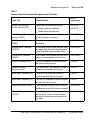
Algorithm details
The selected codec is the type considered as the best bandwidth codec type.
To know whether one codec type has better bandwidth than another, see the
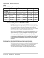
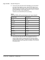
rule as summarized in Table 4 on page 56.
Main Office Configuration for Survivable Remote Gateway 50
Configuration Guide
Page 56 of 258
Bandwidth Management
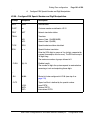
Table 4
“Best Bandwidth” algorithm — codec type
G.711 A law
G.711 mu-law
G.729 A
G. 729 AB
G. 723.1
G.711 A-law
G.711 A-law
G.711 mu-law
G.729 A
G. 729 AB
G. 723.1
G.711 mu-law
G.711 mu-law
G.711 mu-law
G.729 A
G. 729 AB
G. 723.1
G.729 A
G.729 A
G.729 A
G.729 A
G. 729 AB
G.729 A
G. 729 AB
G. 729 AB
G. 729 AB
G. 729 AB
G. 729 AB
G. 729 AB
G. 723.1
G. 723.1
G. 723.1
G.729 A
G. 729 AB
G. 723.1
Interoperability between CS 1000 and SRG
The SRG is designed to interoperate with CS 1000 in a manner similar to
MG 1000B but with a limitation with respect to codec selection policy. Calls
between branch IP Phones and branch analog phones are based on the
interzone policy rather than the intrazone policy defined in the CS 1000 main
office. The zone table is updated based on the intrazone policy.
The net result of this limitation is that calls between branch IP Phone users
and the branch PSTN or between the IP Phones and branch analog phones
will always use a Best Bandwidth codec. However, the calls will be
accounted for as Best Quality. This may impact the perception of call quality
in this scenario, but it will not result in early call blocking. There is no impact
to codec selection or bandwidth usage tracking for calls that require WAN
bandwidth.
Configuring Bandwidth Management parameters
The following sections describe how to configure Bandwidth Management in
a CS 1000 network. Nortel recommends that you read the Bandwidth
Management section in Converging the Data Network with VoIP
(553-3001-160) before using the following configuration information.
553-3001-207
Standard 2.00
January 2006
Bandwidth Management
Page 57 of 258
Zones
Bandwidth Management Zones are configured for each endpoint on a Call
Server. The Network Bandwidth Zone number determines if a call is an
intrazone call or an interzone call. Once that is determined, the proper codec
and bandwidth limit is applied to the call.
All of the endpoints on one Call Server are configured with Zone number to
identify all of the endpoints as being in a unique geographic location in the
network. In addition, Virtual Trunks are configured with a Zone number that
is different from the endpoint Zone numbers in the Call Server.
Codec selection occurs as described in “Codec selection” on page 53.
Configuration rules
There are four configuration rules for Bandwidth Management, as follows:
1
Each Call Server in the network must be configured with a unique VPNI,
with the only exception noted in point 2, next.
2
Branch office (MG 1000B and SRG) Call Servers must be configured
with the same VPNI as that of the main office Call Server with which
they register.
3
Nortel recommends that all the endpoints on a Call Server (IP Phones and
Voice Gateway Media Cards) be configured with the same Zone number.
4
Virtual Trunks must be configured with a different Zone number than the
endpoints.
Network Planning
Before configuring Bandwidth Management in a CS1000 network, follow
these steps:
1
Choose unique VPNIs for all Call Servers in the network.
2
Choose unique Bandwidth Zone numbers for all Call Servers in the
network. These are used when configuring the endpoints (telephones and
gateways) on the Call Server.
Main Office Configuration for Survivable Remote Gateway 50
Configuration Guide
Page 58 of 258
Bandwidth Management
3
Choose unique Bandwidth Zone numbers for the Virtual Trunks in the
network.
4
Choose the codecs that will be enabled on each Call Server.
5
Identify what the interzone codec strategy will be (BB-Best Bandwidth
or BQ-Best Quality) for each zone in the network.
6
Identify what the intrazone codec strategy will be (BB-Best Bandwidth
or BQ-Best Quality) for each zone in the network.
7
Calculate the bandwidth available for intrazone calls for each zone in the
network.
8
Calculate the bandwidth available for interzone calls for each zone in the
network.
9
Calculate the bandwidth available for intrazone calls
Enabling codecs
In Element Manager, select the codecs that will be enabled for calls on the
Call Server, and define the associated parameters, such as payload size. Select
the zone on the Zones web page (see Figure 6 on page 61) and click VGW
and IP phone codec profile. Select an existing codec or configure a new one
in the VGW and IP phone codec profile section, shown in Figure 5 on
page 59. Refer to IP Peer Networking: Installation and Configuration
(553-3001-213) for full instructions on configuring a codec.
553-3001-207
Standard 2.00
January 2006
Bandwidth Management
Page 59 of 258
Figure 5
Configuring a codec
Configuring Bandwidth Management
The steps to configure Bandwidth Management on the Call Server are as
follows:
1
Define a VPNI number in LD 15.
2
Configure the Bandwidth Management parameters for each zone on the
Call Server using either Element Manager (see “Configuration using CS
1000 Element Manager” on page 60) or LD 117 (see “Configuration
using LD 117” on page 61):
•
Call Server zones that will be used for endpoints (telephones and
gateways) with the following properties:
— Intrazone Preferred Strategy = Best Quality (BQ)
— Intrazone Bandwidth = default (1000000)
— Interzone Preferred Strategy = Best Bandwidth (BB)
Main Office Configuration for Survivable Remote Gateway 50
Configuration Guide
Page 60 of 258
Bandwidth Management
— Interzone Bandwidth = maximum bandwidth usage allowed
between peer Call Servers
•
Call Server zones that will be used for Virtual Trunks with the
following properties:
— Intrazone Preferred Strategy = Best Quality (BQ)
— Intrazone Bandwidth = default (1000000)
— Interzone Preferred Strategy = Best Quality (BQ)
— Interzone Bandwidth = default (1000000)
3
Configure the IP Phone, DSP and Virtual Trunk data with the
corresponding zone numbers.
For example, for an IP Phone 2004 telephone in zone 8:
LD 11
REQ NEW
TYPE i2004
...
ZONE 8
...
Configuration using CS 1000 Element Manager
Zones are configured from the Zones web page, shown in Figure 6.
Refer to “Configuring zone parameters using CS 1000 Element Manager” on
page 43 for instructions on configuring a Network Bandwidth Management
zone, using the values given on page 59.
553-3001-207
Standard 2.00
January 2006
Bandwidth Management
Page 61 of 258
Figure 6
Zones web page
Configuration using LD 117
A new Bandwidth Management zone is configured in LD 117 using the
NEW ZONE command. An existing zone can be modified using the
CHG ZONE command.
Main Office Configuration for Survivable Remote Gateway 50
Configuration Guide
Page 62 of 258
Bandwidth Management
LD 117 Configure a new or existing Bandwidth Management zone.
Command
Description
NEW | CHG ZONE <zoneNumber> [<intraZoneBandwidth> <intraZoneStrategy>
<interZoneBandwidth> <interZoneStrategy> <zoneIntent> <zoneResourceType>]
Configure a new zone (NEW) or change (CHG) an existing zone,
where:
• zoneNumber = 0-255
• intraZoneBandwidth = Available intrazone bandwidth (Kbit/s);
Nortel recommends this value be set to the maximum value.
• intraZoneStrategy = BB (Best Bandwidth) or BQ (Best
Quality); Nortel recommends this value be set to BQ.
• interZoneBandwidth =
— For Call Server zone = Maximum bandwidth usage (in
Kbit/s) allowed between peer Call Servers
— For Virtual Trunk zones = 1000000 (Kbit/s)
• interZoneStrategy = BB (Best Bandwidth) or BQ (Best
Quality); Nortel recommends this value be set to BB to
conserve interzone bandwidth.
• zoneIntent = type of zone, where:
— MO = Main Office (Call Server) zone
— BMG = Branch Media Gateway (for branch office zones)
— VTRK = Virtual Trunk zone
• zoneResourceType = resource intrazone preferred strategy,
where:
— shared = shared DSP channels (default)
— private = private DSP channels
Note: In CS 1000 Release 4.5, the zones that were described
with BMG designator stay with BMG one, all the other zones are
provided with MO designator. It is possible to update ZoneIntent
using CHG ZONE command.
553-3001-207
Standard 2.00
January 2006
Bandwidth Management
Page 63 of 258
Maintenance commands
Maintenance commands can be run from Element Manager or LD 117.
Maintenance using Element Manager
The PRT INTRAZONE and PRT INTERZONE commands are available in
Element Manager from the Zones web page, shown in Figure 6 on page 61.
To access these commands, follow the steps in Procedure 3 on page 63.
Procedure 3
Printing intrazone and interzone statistics for a zone
1
Select IP Telephony > Zones from the navigator.
The Zones web page opens, as shown in Figure 6 on page 61.
2
Click Maintenance Commands for Zones (LD 117).
The Maintenance Commands for Zones web page opens, as shown in
Figure 7 on page 64. This page lists all the configured zones.
Main Office Configuration for Survivable Remote Gateway 50
Configuration Guide
Page 64 of 258
Bandwidth Management
Figure 7
Maintenance Commands for Zones web page
3
Do one of the following:
•
•
To display intrazone statistics:
i.
Select Print Interzone Statistics (PRT INTERZONE) from the
Action drop-down list.
ii.
Select a zone from the Zone Number drop-down list, by doing
of the following:
Select ALL to print statistics for all zones.
—
Select a specific zone number to display statistics for a
specific zone.
To display interzone statistics:
i.
553-3001-207
—
Standard 2.00
Select Print Intrazone Statistics per Local Zone
(PRT INTRAZONE) from the Action drop-down list.
January 2006
Bandwidth Management
ii.
4
Page 65 of 258
Select a zone from the Near End Zone Number drop-down list,
by doing of the following:
—
Select ALL to print statistics for all zones.
—
Select a specific zone number to display statistics for a
specific zone.
Click Submit.
The Maintenance Commands for Zones web page reopens, displaying
the statistics for the specified zone or zones. A blank field indicates that
that statistic is either not available or not applicable to that zone.
Figure 8 shows an example of intrazone statistics for a sample Zone 3.
Figure 9 on page 66 shows an example of interzone statistics for the
same Zone 3.
Figure 8
Element Manager — intrazone statistics
Main Office Configuration for Survivable Remote Gateway 50
Configuration Guide
Page 66 of 258
Bandwidth Management
Figure 9
Element Manager — interzone statistics
End of Procedure
Maintenance using LD 117
Use the PRT INTRAZONE or PRT INTERZONE commands in LD 117 to
view the intrazone or interzone statistics for specified zones.
Note: Do not use the PRT ZONE command — it has been replaced by
the PRT INTRAZONE and PRT INTERZONE commands.
553-3001-207
Standard 2.00
January 2006
Bandwidth Management
Page 67 of 258
LD 117 Print zone statistics.
Command
Description
PRT INTRAZONE [<zone>]
Print intrazone statistics for the identified zones, where:
• zone = ALL or 0-255
The output of this command displays the following information:
•
•
•
•
•
•
•
Zone
Type = PRIVATE/SHARED
Strategy = BB/BQ
zoneIntent = MO/VTRK/BMG
Bandwidth = number of Kbps
Usage = number of Kbps
Peak = %
PRT INTERZONE [nearZone>] [<nearVPNI>] [<farZone>] [<farVPNI>]
Print interzone statistics for the specific VPNI zone; where:
• nearZone = ALL or 0-255
The output of this command displays the following information:
•
•
•
•
•
Zone number = 0-255
Zone VPNI = 1-16283
Type= PRIVATE/SHARED
Strategy = BB/BQ
ZoneIntent = MO/VTRK
Adaptive Network Bandwidth Management
Description
The Adaptive Network Bandwidth Management feature enhances the
performance of Voice over Internet Protocol (VoIP) networks based on
real-time interaction. It provides the means to automatically adjust bandwidth
limits and take corrective action in response to Quality of Service (QoS)
Main Office Configuration for Survivable Remote Gateway 50
Configuration Guide
Page 68 of 258
Bandwidth Management
feedback. This dynamic bandwidth adjustment maintains a high level of
voice quality during network degradation.
The Adaptive Network Bandwidth Management feature dynamically adapts
to QoS in the network and reduces the bandwidth available for interzone calls
if QoS degrades. Typically, each Call Server in the network has a zone
assigned to it. The Call Server keeps track of the bandwidth being used
between its own zone and zones belonging to other Call Servers. If the QoS
degrades between the Call Server's zone and a particular zone belonging to
another Call Server, the available bandwidth is reduced automatically
between those two zones. When the QoS between the two zones improves,
then the bandwidth limit is allowed to return to normal.
When an IP Phone encounters degradation of the network, it informs the Call
Server through various QoS alarms. These QoS alarms (packet loss, jitter,
delay, and, for phase 2 IP Phones, R value) get reported to the Call Server.
Depending upon the rate of the incoming alarms and the value of the alarms,
the Call Server reduces the available bandwidth available to make new calls.
The Call Server will lower/limit the number of new calls allowed, based on
the available bandwidth. This prevents excessive calls being placed on a
network with limited bandwidth (resulting in poor voice quality). Once the
adjusted (lowered) bandwidth reaches its full capacity, new calls are either
routed to an alternate route (if available) using Network Alternate Routing
Service (NARS) or the Alternative Routing for NBWM feature (see
Branch Office: Installation and Configuration (553-3001-214)), or new calls
are blocked. The Call Server continues to monitor the network throughout the
network degradation period. When the degradation is removed or the
performance of the network improves, the allowable bandwidth returns to
provisioned levels and the Call Server gradually starts allowing new calls.
Essentially, Adaptive Network Bandwidth Management provides a fallback
to PSTN on QoS degradation for new calls. As a result, bandwidth is managed
and quality measured between all the zones across the entire network, and
when necessary corrective action is taken. Due to the real-time interaction
with the network, less maintenance is required for the network since the
system reacts automatically to network conditions.
With Adaptive Network Bandwidth Management, it is not necessary to
provision bandwidth parameters between every zone in the network. Rather,
the Call Server automatically learns of new zones in the network and applies
553-3001-207
Standard 2.00
January 2006
Bandwidth Management
Page 69 of 258
Adaptive Network Bandwidth Management to these new zones as required.
Therefore, as new Call Servers are added to the network, it is not necessary
to re-provision all the other Call Servers on the network to take into account
this new Call Server. Conversely, when Call Servers are removed from the
network, the remaining Call Servers age out the old Call Server information
and therefore, provide only up to date bandwidth information.
This feature operates between all IP Peer CS 1000 systems, including the
Media Gateway 1000B and Survivable Remote Gateway 50.
Call scenario
A call is requested from a telephone in VPNI 1/Zone 2 on Call Server A to a
telephone in VPNI 3/Zone 3 on Call Server B. Both zones have Adaptive
Network Bandwidth Management enabled.
1
Call Server A contacts the Network Redirect Server to obtain the address
of Call Server B.
2
Call Server A sends a call setup message to Call Server B, identifying the
calling telephone’s VPNI and zone.
3
Call Server B determines if there is sufficient bandwidth for the call, and
sends back the VPNI and zone of the called telephone.
4
Call Server A checks its bandwidth table to determine if there is
sufficient bandwidth available for the call from Call Server A to Call
Server B.
5
If Call Server A determines there is enough bandwidth available, the call
is established; otherwise, alternate treatment is provided in the form of
blocking or rerouting the call.
Both Call Server A and Call Server B must consult their own bandwidth
tables to determine if there is enough bandwidth for the call to proceed.
Figure 10 on page 70 shows this scenario.
Main Office Configuration for Survivable Remote Gateway 50
Configuration Guide
Page 70 of 258
Bandwidth Management
Figure 10
Call Progress with Adaptive Network Bandwidth Management
553-3001-207
Standard 2.00
January 2006
Bandwidth Management
Page 71 of 258
Zone bandwidth management and Adaptive Network Bandwidth
Management
Using Element Manager or the Command Line Interface (CLI), previously
configured zones (except Zone 0) can have the Adaptive Network Bandwidth
Management feature turned on or off. Once turned on, alarm threshold levels
and the QoS coefficients can be adjusted from the default values. Adaptive
Network Bandwidth Management cannot be enabled for Zone 0.
When Adaptive Network Bandwidth Management is enabled for a particular
zone on the Call Server, the zone appears in the zone table. The zone table can
be displayed using Element Manager or LD 117. When a call is made from
the configured zone to another zone, the bandwidth used appears in the zone
table.
When a call is made from a zone with Adaptive Network Bandwidth
Management enabled, to a third party gateway, which has no zone, then the
zone of the Virtual Trunk (VTRK) is used and appears in the zone table.
Figure 11 shows an example of the bandwidth changes.
Figure 11
Adaptive Network Bandwidth Management graph
Main Office Configuration for Survivable Remote Gateway 50
Configuration Guide
Page 72 of 258
Bandwidth Management
When a Call Server receives a QoS alarm, the two zones that originated the
alarm are determined. Using this information, the Call Server reduces the
bandwidth limit between the two zones. This zone-to-zone bandwidth limit
(in effect at any particular time) is known as the Sliding Maximum
Bandwidth Limit and is a percentage of the Configured Interzone bandwidth
limit. The Sliding Maximum value is displayed using the prt interzone
command. The QoS Factor % is also displayed and is the percentage of the
Sliding Maximum versus the configured allowable bandwidth. The Call
Server checks the Network Bandwidth zone management tables for the
originating and terminating zones of the new call to determine the available
bandwidth for the call.
For more information about alarms, refer to Software Input/Output: System
Messages (553-3001-411).
When feedback indicates a significant QoS change in a zone, the Call Server
reduces the available bandwidth (Sliding Maximum Bandwidth Limit) in the
zone until the QoS reaches a satisfactory level. Once satisfactory QoS is
reached, the bandwidth is slowly raised until either the full bandwidth is
available or until QoS degrades again. Bandwidth changes can be configured
to be gradual (to reduce rapid swings and variations) or rapid.
Multiple Appearance Directory Numbers (MADN) can exist on different
zones. Calls to an MADN are handled the same as other IP Phone calls, and
are subject to the same bandwidth limitations.
New SNMP alarms are provided to monitor the system. When the bandwidth
limit between zones is reduced below configured levels, an alarm is raised. A
Warning alarm and an Unacceptable alarm, each corresponding to a drop
below a configured threshold, are used. When the bandwidth returns to
normal, the alarm is cleared. If the bandwidth limit reaches zero, an additional
Unacceptable alarm is raised. These alarms allow the system administrator to
monitor the system and take corrective action when required.
Adaptive Network Bandwidth Management configuration
parameters
Packet Loss (pl), Jitter (j) and Delay (d) measurements, along with the R
factor (r) in IP Phone 200x Phase II telephones, are used to calculate the QoS
level for the zones. The coefficients for these QoS measurements — packet
553-3001-207
Standard 2.00
January 2006
Bandwidth Management
Page 73 of 258
loss (Cpl), jitter (Cj), delay (Cd), and the R factor (Cr) — can be configured
and are used to calculate the rate of bandwidth change. Increasing them from
their default values causes the Sliding Maximum to decrease faster in
response to the specific QoS alarm.
The QoS Coefficient (CQoS) can be varied from its default value. Increasing
this value causes the Sliding Maximum to change more rapidly in response to
QoS alarms. However, making this value too large will result in loss of
overall bandwidth, as shown in Figure 12 below and Figure 13 on page 74.
Figure 12
Effect of the default CQos Coefficient
Main Office Configuration for Survivable Remote Gateway 50
Configuration Guide
Page 74 of 258
Bandwidth Management
Figure 13
Effect of a higher CQoS Coefficient
Other configurable coefficients used in the calculation are the QoS
Coefficient (CQoS), QoS Response Time Increase (ZQRT), and QoS
Response Time Interval (ZQRTI). CQoS, Cr, Cd, Cpl, and Cj control the rate
of bandwidth decrease, while ZQRT and ZQRTI control the rate of
bandwidth increase.
The Call Admission Control (CAC) Validity Time Interval (CACVT) is used
to control the length of time that records from a Call Server are saved in the
Bandwidth Management table. If there have not been any calls between two
Call Servers within the configured time, the Call Server is removed from the
table. For example, if Call Server A has Call Server B in the table, and no call
has been placed between A and B for the CACVT time, then Call Server A
removes all Call Server B records in the table.
Limitations
Virtual Office IP Phones are not subject to bandwidth limitations. They may
not have the correct zone information configured. They can also be controlled
553-3001-207
Standard 2.00
January 2006
Bandwidth Management
Page 75 of 258
by a Call Server that is not responsible for the particular zone. Thus,
bandwidth management is not possible for these phones.
Feature packaging
The Adaptive Network Bandwidth Management feature requires the
following packages:
•
QoS Enhanced Reporting (PVQM) package 401
Note: Package 401, QoS Enhanced Reporting (PVQM), is required if
the R value from the Phase II IP Phones is to be reported and used in the
calculations.
•
Call Admission Control (CAC) package 407
Configuration rules
The configuration rules for Adaptive Network Bandwidth Management are as
follows:
•
Each main office Call Server in a network must have a unique non-zero
VPNI.
•
All branch offices associated with a particular main office must have the
same VPNI as the main office Call Server.
•
All IP Phones (other than specific IP SoftPhone 2050s) and DSP
endpoints on a Call Server must be configured for the same zone.
•
IP SoftPhone 2050s being used remotely must be configured for Zone 0.
•
Branch office systems must tandem all calls through the main office Call
Server to allow bandwidth monitoring and control. In this case, the media
path is direct between the branch office and any point in the network.
•
Trunk Route Optimization (TRO) must be disabled between the main
office Call Server and the SRG. In this case, the media path is direct
between the branch office and any point in the network.
•
Adaptive Network Bandwidth Management parameters are configured
on the main office only and must not be configured at the branch offices.
Main Office Configuration for Survivable Remote Gateway 50
Configuration Guide
Page 76 of 258
Bandwidth Management
Configuring Adaptive Network Bandwidth Management
The following is a summary of the tasks necessary to configure Adaptive
Network Bandwidth Management in the network.
1
Enable the Call Admission Control (CAC) package.
2
Configure CAC in Element Manager or LD 117:
a
Configure the VPNI on the main office and branch offices.
b
Configure both the main office and branch office zones at the main
office.
c
Configure the branch office zone on the SRG.
d
Configure the interzone and intrazone bandwidth limits at the main
office and SRG.
e
Enable Adaptive Network Bandwidth Management for the zones on
the main office Call Server.
f
If required, alter the Adaptive Network Bandwidth Management
parameters in keeping with the information in “Advanced
Configuration Notes” below.
3
Tandem the outbound branch office calls by configuring the NRS.
4
Tandem the inbound branch office calls by creating a dialing plan which
routes all calls destined for the branch office through the main office.
Advanced Configuration Notes
553-3001-207
1
The default values for Cpl, Cj, Cd, Cr and CQos can be increased to
increase the response time for Sliding Maximum changes. However,
increasing them can cause the Sliding Maximum to temporarily decrease
to a lower value then necessary, resulting in the needless blocking of
interzone calls.
2
Increasing the value of ZQRT will increase the speed at which the
Sliding Maximum increases. The same effect can be achieved by
decreasing ZQRTI. However, changing these values can cause the
Sliding maximum to oscillate until the network degradation is removed.
3
It may be necessary to change the notification level (ZQNL) of the Call
Server so it can react to the QoS alarms. Use LD 117 to change this level.
Standard 2.00
January 2006
Bandwidth Management
Page 77 of 258
Refer to Converging the Data Network with VoIP (553-3001-160) for
information on notification levels for alarms.
Configuration using Element Manager
Element Manager can be used to enable and configure the feature.
The zone must exist before it can be configured for Adaptive Network
Bandwidth Management. Refer to IP Peer Networking: Installation and
Configuration (553-3001-213) for instruction on how to create and configure
basic properties of the zone.
To configure the Adaptive Network Bandwidth Management feature, select a
zone on the Zones web page (see Figure 6 on page 61) and click Adaptive
Network Bandwidth Management and CAC. The Adaptive Network
Bandwidth Management and CAC web page opens, as shown in Figure 14
on page 78.
Note: Do not configure Adaptive Networks Bandwidth Management for
Zone 0 or Virtual Trunk zones.
Main Office Configuration for Survivable Remote Gateway 50
Configuration Guide
Page 78 of 258
Bandwidth Management
Figure 14
Adaptive Network Bandwidth Management and CAC web page
If the Adaptive Network Bandwidth Management feature is enabled using the
Enable Call Admission Control feature (ZCAC) check box, then the other
parameters can be adjusted as required.
Table 5 on page 79 shows the fields in the Adaptive Network Bandwidth
Management and CAC web page, the field definitions, and their LD 117
command equivalent.
553-3001-207
Standard 2.00
January 2006
Bandwidth Management
Page 79 of 258
Table 5
Adaptive Network Bandwidth Management and CAC fields
Field Title
Field Definition
LD 117
equivalents
Enable Call Admission
Control Feature (CAC)
Control the CAC feature for the zone
ENL ZCAC
• Enable (check box selected)
• disable (clear the check box)
DIS ZCAC
QoS Response Time
Increase (ZQRT)
Bandwidth limit increment, as a percentage
of the QoS factor for the zone
CHG ZQRT
QoS Response Time Interval
(ZQRTI)
Time (in minutes) between bandwidth limit
increments
CHG ZQRTI
Warning Alarm Threshold
(ZQWAT)
A QoS value, which is lower than this value,
but higher than the Critical (Unacceptable)
Alarm Threshold, triggers a Major Alarm.
CHG ZQWAT
Critical Alarm Threshold
(ZQUAT)
A QoS value, which is lower than this value,
triggers an Unacceptable (Critical) Alarm.
CHG ZQUAT
R Alarm Coefficient (CR)
The R (Cr) coefficient is used to calculate
the QoS value for the zone.
CHG CR
Packet Loss Alarm
Coefficient (CPL)
The Packet Loss (Cpl) coefficient is used to
calculate the QoS value for the zone.
CHG CPL
Delay Alarm Coefficient (CD)
The Delay (Cd) coefficient is used to
calculate the QoS value for the zone.
CHG CD
Jitter Alarm Coefficient (CJ)
The Jitter (Cj) coefficient is used to calculate
the QoS value for the zone.
CHG CJ
Coefficient of QoS (CQoS)
The Coefficient of QoS (CQoS) is used to
calculate the overall QoS value for the zone.
CHG CQOS
Recent Validity Time Interval
(CACVT)
Amount of time (in hours) for zone-to-zone
record validity. Once this interval expires,
records for unused zones are purged from
the tables.
CHG CACVT
Main Office Configuration for Survivable Remote Gateway 50
Configuration Guide
Page 80 of 258
Bandwidth Management
Configuration using Command Line Interface
You can also configure the Adaptive Network Bandwidth Management
feature using LD 117.
LD 117 — Configure Adaptive Network Bandwidth Management. (Part 1 of 6)
Command
Description
CHG CACVT <Zone> <Interval>
Configure the zone-to-zone record validity time interval, where:
• Zone = 1-255
• Interval = 1-(48)-255
CHG CD <Zone> <Cd>
Change the Cd coefficient in the formula that determines how quickly an alarm
reduces the Sliding Maximum bandwidth for the identified zone, where:
• Zone = 1-255
• Cd = Cd coefficient = 1-(50)-100
CHG CPL <Zone> <Cpl>
Change the Cpl coefficient in the formula that determines how quickly an
alarm reduces the Sliding Maximum bandwidth for the identified zone, where:
• Zone = 1-255
• Cpl = Cpl coefficient = 1-(50)-100
CHG CJ <Zone> <Jitter>
Change the Cj coefficient in the formula that determines how quickly an alarm
reduces the Sliding Maximum bandwidth for the identified zone, where:
• Zone = 1-255
• Jitter = Jitter coefficient = 1-(50)-100
553-3001-207
Standard 2.00
January 2006
Bandwidth Management
Page 81 of 258
LD 117 — Configure Adaptive Network Bandwidth Management. (Part 2 of 6)
Command
Description
CHG CQOS <Zone> <QoS>
Change the QoS coefficient in the formula that determines how quickly an
alarm reduces the Sliding Maximum bandwidth for the identified zone, where:
• Zone = 1-255
• QoS = QoS coefficient = 1-(50)-100
CHG CR <Zone> <Cr>
Change the Cr coefficient in the formula that determines how quickly an alarm
reduces the Sliding Maximum bandwidth for the identified zone, where:
• Zone = 1-255
• Cr = Cr coefficient = 1-(50)-100
Main Office Configuration for Survivable Remote Gateway 50
Configuration Guide
Page 82 of 258
Bandwidth Management
LD 117 — Configure Adaptive Network Bandwidth Management. (Part 3 of 6)
Command
Description
CHG ZONE <zoneNumber> <intraZoneBandwidth> <intraZoneStrategy>
<interZoneBandwidth> <interZoneStrategy> [<zoneIntent> <zoneResourceType>]
Change the parameters of an existing zone, where:
• zoneNumber = 1-255
• intraZoneBandwidth = 1000000 (Mbit/s)
• intraZoneStrategy = intrazone preferred strategy
— Best Quality = BQ
— Best Bandwidth = BB
• interZoneBandwidth = 1000000 (Mbit/s)
• interZoneStrategy = intrazone preferred strategy
— Best Quality = BQ
— Best Bandwidth = BB
• zoneIntent = type of zone, where:
— MO = Main Office zone
— BMG = Branch Media Gateway (branch office) zone
— VTRK = Virtual Trunk zone
• zoneResourceType = resource intrazone preferred strategy
— shared DSP channels (default) = shared
— private DSP channels = private
Note: In CS 1000 Release 4.5, the zones that were described with BMG
designator stay with BMG one, all the other zones are provided with MO
designator. It is possible to update ZoneIntent using the CHG ZONE
command.
CHG ZQRT <Zone> <Incr>
Change ZQRT, which is Response time increase by percentage. It is used to
determine the increase to the Sliding Maximum for the identified zone, where:
• Zone = 1-255
• Incr = increase value in percentage = 1-(10)-100
553-3001-207
Standard 2.00
January 2006
Bandwidth Management
Page 83 of 258
LD 117 — Configure Adaptive Network Bandwidth Management. (Part 4 of 6)
Command
Description
CHG ZQRTI <Zone> <Interval>
Change the QoS Response Time Interval while alarms are not coming, in
order to increase the Sliding Maximum for the identified zone, where:
• Zone = 1-255
• Interval = interval in minutes = 1-(5)-120
CHG ZQUAT <Zone> <Thres>
Change the QoS Unacceptable Alarm Threshold value for the identified zone,
where:
• Zone = 1-255
• Thres = threshold value = 1-(75)-99
Note: When the zone-to-zone QoS value drops below the threshold value,
the alarm is presented. When the zone-to-zone QoS value is greater than this
threshold value, this alarm is presented as being deactivated. This value must
be below the value of ZQWAT.
CHG ZQWAT <Zone> <Thres>
Change the QoS Warning Alarm Threshold value for the identified zone,
where:
• Zone = 1-255
• Thres = threshold value = 1-(85)-99
Note: When the zone-to-zone QoS value drops below the threshold value,
the alarm is presented. When the zone-to-zone QoS value is greater than this
threshold value, this alarm is presented as being deactivated. The value for
ZQWAT must be higher than the value of ZQUAT.
Main Office Configuration for Survivable Remote Gateway 50
Configuration Guide
Page 84 of 258
Bandwidth Management
LD 117 — Configure Adaptive Network Bandwidth Management. (Part 5 of 6)
Command
Description
CHG ZQNL <ZoneNumber> <level>
Change the Notification Level for the specified zone, where:
• Zone = 1-255
• Level = 0-(2)-4, where:
— Level 0 = All voice quality alarms are suppressed.
— Level 1 = All zone-based Unacceptable alarms.
— Level 2 = Allow all level 1 alarms PLUS zone-based Warning alarms.
— Level 3 = Allow all level 1 and 2 alarms PLUS per-call Unacceptable
alarms.
— Level 4 = Allow all level 1, 2, and 3 alarms PLUS per-call Warning
alarms.
NEW ZONE <zoneNumber> [<intraZoneBandwidth> <intraZoneStrategy>
<interZoneBandwidth> <interZoneStrategy> <zoneIntent> <zoneResourceType>]
•
•
•
•
•
zoneNumber = 1-255
intraZoneBandwidth = 1000000 (Mbit/s)
intraZoneStrategy = BQ (Best Quality)
interZoneBandwidth = 1000000 (Mbit/s)
interZoneStrategy = intrazone preferred strategy
— Best Quality = BQ
— Best Bandwidth = BB
• zoneIntent = type of zone, where:
— MO = Main Office zone
— BMG = Branch Media Gateway (branch office) zone
— VTRK = Virtual Trunk zone
• zoneResourceType = resource intrazone preferred strategy
— shared DSP channels (default) = shared
— private DSP channels = private
553-3001-207
Standard 2.00
January 2006
Bandwidth Management
Page 85 of 258
LD 117 — Configure Adaptive Network Bandwidth Management. (Part 6 of 6)
Command
Description
DIS ZCAC <Zone>
Disables the Call Admission Control (CAC) feature for the specified zone,
where:
• Zone = 1-255
Note: Disables the feature on a zone-by-zone basis.
ENL ZCAC <Zone>
Enables the Call Admission Control (CAC) feature for the specified zone,
where:
• Zone = 1-255
Note: Enables the feature on a zone-by-zone basis.
Maintenance commands
The Adaptive Network Bandwidth Management feature can be maintained
using Element Manager or LD 117.
Maintenance using Element Manager
The CAC parameters, intrazone statistics, and interzone statistics for one of
more zones are available in Element Manager from the Zones web page,
shown in Figure 6 on page 61. To view the intrazone or interzone statistics,
use Procedure 3 on page 63. To display the CAC parameters, follow the steps
in Procedure 4.
Procedure 4
Displaying CAC parameters for one or more zones
1
Select IP Telephony > Zones from the navigator.
The Zones web page opens (see Figure 6 on page 61).
Main Office Configuration for Survivable Remote Gateway 50
Configuration Guide
Page 86 of 258
Bandwidth Management
2
Click Maintenance Commands for Zones (LD 117).
The Maintenance Commands for Zones web page opens, as shown in
Figure 7 on page 64. This page lists all the configured zones and their
intrazone statistics by default.
3
Select Print Adaptive Network Bandwidth Management and CAC
Parameters (PRT ZCAC) from the Action drop-down list.
4
Select a zone from the Zone Number drop-down list, by doing one of the
following:
5
•
Select ALL to print statistics for all zones.
•
Select a specific zone number to display statistics for a specific zone.
Click Submit.
The Maintenance Commands for Zones web page reopens, displaying
the statistics for the specified zone or zones. A blank field indicates that
that statistic is either not available or not applicable to that zone.
Figure 15 on page 87 shows an example of the CAC parameters for
sample Zone 3.
553-3001-207
Standard 2.00
January 2006
Bandwidth Management
Page 87 of 258
Figure 15
Element Manager — CAC parameters
End of Procedure
Main Office Configuration for Survivable Remote Gateway 50
Configuration Guide
Page 88 of 258
Bandwidth Management
Maintenance using LD 117
The same information can be displayed using commands in LD 117.
LD 117 — Display Adaptive Network Bandwidth Management information
(Part 1 of 3)
Command
Description
CLR CACR <nearZone> [<nearVPNI>] [<farZone>] [<farVPNI>]
Clear zone-to-zone record for near (VPNI-Zone) for far (VPNI-Zone), where:
•
•
•
•
nearZone = 0-255
nearVPNI = 1-16383
farZone = 0-255
farVPNI = 1-16383
PRT INTRAZONE [<zone>]
Print intrazone statistics for the identified zones, where:
• zone = ALL or 1-255
The output of this command displays the following information:
• Zone
• State = ENL/DIS
• Type = PRIVATE/SHARED
• Strategy = BB/BQ
• MO/VTRK/BMG = zoneIntent
• Bandwidth = Kbps
• Usage = Kbps
• Peak = %
Figure 16 on page 91 shows an example of the output for this command.
553-3001-207
Standard 2.00
January 2006
Bandwidth Management
Page 89 of 258
LD 117 — Display Adaptive Network Bandwidth Management information
(Part 2 of 3)
Command
Description
PRT INTERZONE [<nearZone>] [<nearVPNI>] [<farZone>] [<farVPNI>]
Print interzone statistics for the specific VPNI zone; where:
•
•
•
•
nearZone = ALL or 0-255
nearVPNI = 1-16383
farZone = 0-255
farVPNI = 1-16383
The output of this command displays the following information:
•
•
•
•
•
•
•
•
•
•
•
•
•
•
•
Near end Zone
Near end VPNI
Far end Zone
Far end VPNI
State = ENL/DIS
Type = PRIVATE/SHARED
Strategy = BB/BQ
MO/VTRK/BMG = zoneIntent
QoS factor = %
Bandwidth configured = Kbps
Sliding max = Kbps
Usage = Kbps
Peak = %
Call = Cph
Alarm = Aph
The report rows are grouped as:
• First row = summary bandwidth usage per near zone
• Next rows = bandwidth usage per near (VPNI- Zone) and far (VPNI Zone)
Figure 17 on page 92 shows an example of the output for this command.
Main Office Configuration for Survivable Remote Gateway 50
Configuration Guide
Page 90 of 258
Bandwidth Management
LD 117 — Display Adaptive Network Bandwidth Management information
(Part 3 of 3)
Command
Description
PRT ZCAC [<zone>]
Print CAC parameters for the specified zone, or for all zones, where:
• zone = ALL or 0-255
The output of this command displays the following information:
•
•
•
•
•
•
•
•
•
•
•
•
Local ZONE = 0-255
State = ENL/DIS
CR = 1-100
CPL = 1-100
CD = 1-100
CJ = 1-100
CQOS = 1-100
ZQRT = 1-100
ZQRTI = 10-120
ZQUAT = 1-99
ZQWAT =1-99
CACVT = 1-255
Sample outputs for PRT commands
Figure 16 on page 91 shows an example of the output of the PRT
INTRAZONE command. Figure 17 on page 92 shows an example of the
output of the PRT INTERZONE command.
553-3001-207
Standard 2.00
January 2006
Bandwidth Management
Page 91 of 258
Figure 16
Sample output for PRT INTRAZONE command
=> prt intrazone
_______________________________________________________________
|Zone|State| Type |Strategy|MO/ | Bandwidth | Usage | Peak |
|
|
|
|
|VTRK/| kbps
|
kbps |
% |
|
|
|
|
|BMG |
|
|
|
|----|-----|-------|--------|----|-----------|---------|------|
|
2| ENL |SHARED |
BQ
| MO|
10000|
190|
3 |
|-------------------------------------------------------------|
| 44| ENL |SHARED |
BQ
| BMG|
10000|
0|
1 |
|-------------------------------------------------------------|
Number of Zones configured = 2
Main Office Configuration for Survivable Remote Gateway 50
Configuration Guide
553-3001-207
Standard 2.00
January 2006
Note: The Far end and VPNI fields are displayed only when Adaptive Bandwidth Management is enabled in LD 117.
|Near end |Far end
|State| Type |Stra|MO/ |QoS|Bandwidth | Sliding | Usage |Peak| Calls | Alarm |
|
|
|
|
|tegy|BMG/|Fac|Configured |
max
|
|
|
|
|
|
|
|
|
|
|VTRK|tor|
|
|
|
|
|
|
|----------|----------|-----|-------|----|----|---|-----------|---------|---------|----|---------|---------|
|Zone|VPNI |Zone|VPNI |
|
|
|
| % |
kbps
|
kbps |
kbps | % |
Cph
|
Aph
|
|----|-----|----|-----|-----|-------|----|----|---|-----------|---------|---------|----|---------|---------|
|
2|
|
|
| ENL |SHARED | BB| MO|
|
10000|
|
78|
1|
|
|
|----------------------------------------------------------------------------------------------------------|
|
2|
1| 33|
1| ENL |SHARED | BB| MO|100|
10000|
|
78|
1|
1|
0|
|----------------------------------------------------------------------------------------------------------|
| 33|
|
|
| ENL |SHARED | BB| BMG|
|
10000|
|
78|
1|
|
|
|----------------------------------------------------------------------------------------------------------|
| 33|
1|
2|
1| ENL |SHARED | BB| BMG|100|
10000|
|
78|
1|
1|
0|
|----------------------------------------------------------------------------------------------------------|
Number of Zones configured = 1
=> prt interzone
Page 92 of 258
Bandwidth Management
Figure 17
Sample output for PRT INTERZONE command
Bandwidth Management
Page 93 of 258
Tandem Bandwidth Management overview
In order for the main office to correctly keep track of all the bandwidth being
used to and from a branch office the call must be tandemed through the main
office. When calls are tandemed through the main office only the signaling is
tandemed, the actual voice bandwidth travels directly between the source and
destination.
Bandwidth utilization for the branch office is tracked at the main office and
can be displayed in LD 117 using the PRT INTERZONE command. In order
to provide the correct bandwidth utilization to the main office Call Server,
when a branch office is calling another node in the network, the calls must be
tandemed through the main office Call Server in both the inbound and
outbound direction.
Entering the main office Gateway endpoint identifier in the Tandem Endpoint
field for each branch office gateways configured on the NRS only provides
tandeming in the outbound direction from each branch office (from branch
office to main office).
In order to tandem calls through the main office in the inbound direction
(from main office to branch office), one must make use of the dialing plan
capabilities of the CS 1000 to first route the call to the main office. The main
office prepends a prefix to the dialed number and the number is routed to the
branch office.
Tandeming all branch office calls through the main office allows the main
office to keep track of the bandwidth being used at each branch office.
Application
This feature applies to the branch office and the Adaptive Bandwidth
Management feature. Specifically, it applies to calls made to and from the
branch office from either telephones registered locally at the branch office
(digital, analog [500/2500-type], and IP Phones) or trunks at the branch office
to another node in the network. It does not apply when using branch office IP
Phones that are registered with the main office (for example, Normal Mode).
Main Office Configuration for Survivable Remote Gateway 50
Configuration Guide
Page 94 of 258
Bandwidth Management
Patch Number
A patch is required on the main office in order to invoke this feature. The
patch number is MPLR 20259.
Dialing Plan Overview
Depending upon the type of dialing plan used in the network (Coordinated
Dialing Plan [CDP], or Uniform Dialing Plan [UDP] or a combination of
both) the general idea is to have all calls that are terminating at a branch office
first dial a number that will get routed to the main office associated with that
branch office. The main office recognizes this number as belonging to the
branch office and appends a tandem prefix to this number using Digit
Manipulation Index (DMI). The main office then routes the call to the branch
office while accounting for the additional bandwidth used.
See Figure 18 for an example of a tandem call.
Figure 18
A call between two branch offices tandems through the main office
Figure 19 on page 95 shows a general legend for the figures in the following
section.
553-3001-207
Standard 2.00
January 2006
Bandwidth Management
Page 95 of 258
Figure 19
General legend
Main Office Configuration for Survivable Remote Gateway 50
Configuration Guide
Page 96 of 258
Bandwidth Management
Network using Uniform Dialing Plan
The following section provides general network configuration for a network
using UDP only.
Figure 20 shows two or more main offices with their branch offices, within a
larger network. Callers within each main office/branch office “region” use
UDP to place calls between systems. Callers also use UDP to place calls
across the IP network to the other main office(s) and its (their) branch offices.
In a typical network, a full region uses a single Home Location Code
(HLOC). However, it is also possible, where the number of users requires it,
to have two or more codes, although using one for the main office and one for
each branch office is unlikely at best.
Figure 20
Scenario 1: UDP throughout the network
Common details
In general, if an HLOC is shared between two or more systems, the
provisioning at the main office gets more complex, unless all branch offices
share HLOCs with the main office. That is, if the main office has two or more
HLOCs, and one or more of these (but not necessarily the same one) is used
by every branch office, then provisioning is relatively straight forward.
553-3001-207
Standard 2.00
January 2006
Bandwidth Management
Page 97 of 258
Table 6 describes the network configuration and the steps that a call takes
during its setup.
Table 6
Configuration details for the general case
Region
Call progress
steps
Configuration detail and call progress
during call setup
1, 2, 3
UDP used for all calls within the region.
1, 2, 3
UDP used for region to region calls.
1, 2, 3
Prefixes for branch offices for regular calls are
required for all branch offices. May have additional
prefixes for E-911 calls, if required, or may share
prefixes.
1
1
All branch offices are provisioned at the NRS to route
all outbound calls (from the branch office) through
the main office. (NRS tandem configuration).
1
2
Main office sends all UDP calls to destinations that
are not its own branch office to the NRS with
unchanged dialled digits.
1
3
Main office sends all UDP calls to destinations that
are its own branch office to the NRS with a specific
gateway prefix in front of the dialled digits.
1
4
All branch offices delete the prefix and any LOC
codes, and terminate the calls. May be to a local set
or to a trunk.
2,3
Similar call setup steps take places for calls within
region 2 and 3.
Main Office Configuration for Survivable Remote Gateway 50
Configuration Guide
Page 98 of 258
Bandwidth Management
Differences when every branch office HLOC is shared with the
main office
Table 7 shows the configuration when the branch office HLOC is shared with
the main office.
Table 7
Provisioning details for this case
Region
Provisioning detail
1
Provisioning on the main office requires parsing to only
“normal” LOC identification and HLOC deletion.
1
LOC values that are on branch offices may be provisioned as
extended LOCs (> 3 digit codes).
1
The DMI for the branch office “LOC” inserts a gateway routing
prefix in front of the number.
2,3
Similar configuration, as above, applies to regions 2 and 3.
Call between two branch offices associated with the same
main office
The following scenarios describe calls between two branch offices that
belong to the same main office. the different scenarios described below vary
vary in the manner in which the HLOC is architected; branch offices have
same HLOC as the main office, branch offices have a different HLOC than
the main office and so on.
Every branch office HLOC is shared with the main office
In the following example, the HLOC of all the branch offices and the HLOC
of the main office are all the same. See Figure 21 on page 99.
553-3001-207
Standard 2.00
January 2006
Bandwidth Management
Page 99 of 258
Figure 21
Call flow for Scenario 1 - local call
1
The branch office user dials 6-395-3456. The system transmits 395-3456
to the NRS. The NRS checks its provisioning, and determines that all
calls are to be sent to the main office; it directs the call to the main office.
2
The branch office sends the call to 395-3456 to the main office.
3
The main office determines that this is LOC 39534, to another branch
office, with gateway routing prefix 552. The system inserts the prefix and
transmits 552-395-3456 to the NRS. The NRS checks its provisioning,
and determines that all calls to prefix 552 are to be sent to branch office
A2; it directs the call to the branch office.
4
The main office sends the call to 552-395-3456 to the branch office. The
branch office deletes the prefix and the HLOC, and rings set 3456.
Main Office Configuration for Survivable Remote Gateway 50
Configuration Guide
Page 100 of 258
Bandwidth Management
No branch office HLOC is shared with the main office, but can
be shared with another branch office
In this example, the HLOC of the branch offices are the same but the HLOC
of the main office is different. See Figure 22.
Figure 22
Call flow for Scenario 1 - local call
553-3001-207
1
The branch office user dials 6-395-3456. The system transmits 395-3456
to the NRS. The NRS checks its provisioning, and determines that all
calls are to be sent to the main office; it directs the call to the main office.
2
The branch office sends the call to 395-3456 to the main office.
Standard 2.00
January 2006
Bandwidth Management
Page 101 of 258
3
The main office determines that this is LOC 39534 to another branch
office, with gateway routing prefix 552. The system inserts the prefix and
transmits 552-395-3456 to the NRS. The NRS checks its provisioning,
and determines that all calls to prefix 552 are to be sent to branch office
A2; it directs the call to the branch office.
4
The main office sends the call to 552-395-3456 to the branch office. The
branch office deletes the prefix and the HLOC and rings set 3456.
No branch office HLOC is shared with the main office or
another branch office
In this example, the HLOC is unique between all the branch offices and the
main office. See Figure 23.
Figure 23
Call flow for Scenario 1- local call
Main Office Configuration for Survivable Remote Gateway 50
Configuration Guide
Page 102 of 258
Bandwidth Management
1
The branch office user dials 6-395-3456. The system transmits 399-3456
to the branch office user dials 6-399-3456. NRS. The NRS checks its
provisioning, and determines that all calls are to be sent to the main
office; it directs the call to the main office.
2
The branch office sends the call to 399-3456 to the main office.
3
The main office determines that this is to another branch office, with
office prefix 552. The system inserts the prefix and transmits
552-399-3456 to the NRS. The NRS checks its provisioning, and
determines that all calls to prefix 552 are to be sent to branch office A2;
it directs the call to the branch office.
4
The main office sends the call to 552-399-3456 to the branch office. The
branch office deletes the prefix and the HLOC, and rings set 3456.
Call between branch offices associated with different main
office
The following scenarios describe calls between two branch offices that
belong to different main offices. Note that the different scenarios described
below vary in the manner in which the HLOC is architected; branch offices
have same HLOC as the main office, branch offices have a different HLOC
than the main office and so on.
Every branch office HLOC is shared with the main office
In Figure 24 on page 103, the first half of the call setup is shown (the
originator side is side A). In this example, the branch office and the main
office share the same HLOC. In Figure 25 on page 104, the second half of the
call is shown (the terminating side is side B).
553-3001-207
Standard 2.00
January 2006
Bandwidth Management
Page 103 of 258
Figure 24
Call flow for Scenario 1 – call to a remote branch office (originator side)
1
The branch office user dials 6-444-3456. The system transmits 444-3456
to the NRS. The NRS checks its provisioning, and determines that all
calls are to be sent to the main office; it directs the call to the main office.
2
The branch office sends the call to 444-3456 to the main office.
3
The main office determines that this is to another main office. The
system transmits 444-3456 to the NRS. The NRS checks its
provisioning, and determines that this call goes to main office B.
Main Office Configuration for Survivable Remote Gateway 50
Configuration Guide
Page 104 of 258
Bandwidth Management
Figure 25
Call flow for Scenario 1 - call to remote branch office (destination side)
553-3001-207
1
Main office B determines that this is to LOC 44434, which is a local
branch office with prefix 225. The system transmits 225-444-3456 to the
NRS. The NRS checks its provisioning, and determines that this call goes
to branch office B1.
2
The main office sends the call to 225-444-3456 to the branch office. The
branch office deletes the prefix, discovers the call is to its HLOC 444,
deletes the HLOC, and rings set 3456.
Standard 2.00
January 2006
Bandwidth Management
Page 105 of 258
No branch office HLOC is shared with the main office,
but can be shared with another branch office
In Figure 26, the first half of the call is shown (originator side of the call). In
Figure 27 on page 106, the second half of the call is shown (destination side
of the call).
Figure 26
Call flow for Scenario 1 - call to remote branch office (originator side)
1
The branch office user dials 6-444-3456. The system transmits 444-3456
to the NRS. The NRS checks its provisioning, and determines that all
calls are to be sent to the main office; it directs the call to the main office.
2
The branch office sends the call to 444-3456 to the main office.
3
The main office determines that this is to another main office. The
system transmits 444-3456 to the NRS. The NRS checks its
provisioning, and determines that this call goes to main office B.
Main Office Configuration for Survivable Remote Gateway 50
Configuration Guide
Page 106 of 258
Bandwidth Management
Figure 27
Call flow for Scenario 1 - call to remote branch office (destination side)
1
Main office B determines that this LOC plus digits is to a local branch
office with prefix 225. (If sharing this LOC with another branch office,
the extended LOC is 44434.) The system transmits 225-444-3456 to the
NRS. The NRS checks its provisioning, and determines that this call goes
to branch office B1.
2
The main office sends the call to 225-444-3456 to the branch office. The
branch office deletes the prefix, and the HLOC, and rings set 3456.
No branch office HLOC is shared with the main office or
another branch office
The following example shows a call between two branch offices. In this
example, the HLOC is unique between the main office and branch office. In
Figure 28, the first half of the call is shown (originator side of the call). In
Figure 29 on page page 108, the second half of the call is shown (destination
side of the call).
553-3001-207
Standard 2.00
January 2006
Bandwidth Management
Page 107 of 258
Figure 28
Call flow for Scenario 1 - call to remote branch office (originator side)
1
The branch office user dials 6-444-3456. The system transmits 444-3456
to the NRS. The NRS checks its provisioning, and determines that all
calls are to be sent to the main office; it directs the call to the main office.
2
The branch office sends the call to 444-3456 to the main office.
3
The main office determines that this is to another main office. The
system transmits 444-3456 to the NRS. NRS checks its provisioning, and
determines that this call goes to main office B.
Main Office Configuration for Survivable Remote Gateway 50
Configuration Guide
Page 108 of 258
Bandwidth Management
Figure 29
Call flow for Scenario 1 - call to remote branch office (destination side)
1
Main office B determines that LOC 444 is to a local branch office with
prefix 225. The system transmits 225-444-3456 to the NRS. The NRS
checks its provisioning, and determines that this call goes to branch
office B1.
2
The main office sends the call to 225-444-3456 to the branch office. The
branch office deletes the prefix, discovers the call is to its HLOC, deletes
the HLOC, and rings set 3456.
Summary of provisioning procedures
for Tandem Bandwidth Management
Use Procedure 5 on page 110 to provision the network.
553-3001-207
1
Enter the main office Gateway endpoint identifier in the Tandem
Endpoint field for each branch office gateway configured on the NRS.
This provides tandeming for outbound calls from a branch office through
its main office. See step 1 on page 110.
2
Plan the gateway routing prefixes, if not already done. At least one prefix
is needed per branch office, although any branch offices that have a
prefix for ESA “911” calls does not necessarily require another. (These
prefixes will be SPN - Special Number - entries.) See step 2 on page 111.
Standard 2.00
January 2006
Bandwidth Management
Page 109 of 258
3
Provision the NRS to send all calls to a LOC without a gateway routing
prefix to the main office of that LOC, or to the main office which
provides service for the branch office using the LOC. See step 3 on
page 111.
4
Provision the NRS to send all calls to a LOC with a gateway routing
prefix to the branch office directly. Using the gateway routing prefix and
the Type of Number of SPN, the entries can be differentiated from the
normal LOCs easily. See step 4 on page 111.
5
Provision the main office with the DGT table DMIs to insert the prefixes
and set the Type of Number correctly. Create RLB RLI entries to use
these DMIs for the VTRK route(s). One RLI per branch office will be the
minimum requirement. Note that calls from remote systems will
typically have the HLOC prefix, so this is defined here. See step 5 on
page 112.
6
Provision the main office with CDP DSCs (mapped by the RLI into
Location Codes) sufficient to uniquely identify all of its branch offices
(using extended location codes, if required); use the RLI index defined
for each branch office as the RLI value of the LOC definition. This is the
route to the branch office. See step 6 on page 112.
7
Provision the main office and branch office with a home location code
(HLOC) or multiple codes to terminate all calls that should terminate on
this system. See step 7 on page 113.
8
Provision the main office to send all other LOCs to the IP network
without prefixes. These are going to a remote main office. See step 8 on
page 114.
9
Provision the branch office with a terminating RLI with a DMI to delete
the LOC prefixes. See step 9 on page 115.
Provisioning Example of Tandem Bandwidth Management
Figure 30 shows an example of the network configuration.
Main Office Configuration for Survivable Remote Gateway 50
Configuration Guide
Page 110 of 258
Bandwidth Management
Figure 30
Provisioning example
Procedure 5
Provisioning Tandem Bandwidth Management
1
Enter the main office Gateway endpoint identifier in the Tandem Endpoint
field for each branch office GW configured on the NRS.This provides
tandeming for outbound calls from a branch office through its main office.
Figure 31 shows the tandem endpoint configuration in Element Manager.
553-3001-207
Standard 2.00
January 2006
Bandwidth Management
Page 111 of 258
Figure 31
Tandem endpoint configuration in Element Manager
2
Plan the gateway routing prefixes. At least one prefix is needed per
branch office, although any branch offices that have a prefix for ESA “911”
calls does not necessarily require another. (These prefixes will be SPN
- Special Number - entries if you are using ESA 911. In the example these
are LOC codes because network 911 is not being used.)
In our example the Branch office prefixes are 741 (branch office B) and
742 (branch office A).
3
Provision the NRS to send all calls to a LOC without a gateway routing
prefix to the main office of that LOC, or to the main office which provides
service for the branch office using the LOC. In our example the NRS is
provisioned with 841 (for main office B) and 842 (for main office A).
4
Provision the NRS to send all calls to a LOC with a gateway routing prefix
to the branch office directly. Using the gateway routing prefix and the
Type of Number as used (LOC or SPN), the entries can be differentiated
from the normal LOCs easily.
In our example the NRS is provisioned with 741-841 at branch office B
and 742-842 for branch office A.
Main Office Configuration for Survivable Remote Gateway 50
Configuration Guide
Page 112 of 258
Bandwidth Management
5
Provision the main office with the DGT table DMIs to insert the prefixes
and set the Type of Number correctly. Create RLB RLI entries to use
these DMIs for the VTRK route(s). One RLI per branch office will be the
minimum requirement. Note that calls from remote systems will typically
have the HLOC prefix, so this is defined here
Table 8 lists main office B DMI and RLI provisioning.
Table 8
Main office B DMI and RLI provisioning (for calls in branch office B)
6
553-3001-207
Create a DMI
Create an RLI
LD 86
LD 86
REQ new
REQ new
CUST 0
CUST 0
FEAT dgt
FEAT rlb
DMI 50
RLI 50
DEL 0
ENTR 0
ISPN no
LTER no
INST 741841
ROUT 71
CTYP loc
DMI 50
Provision the main office with CDP DSCs (mapped by the RLI into
Location Codes) sufficient to uniquely identify all of its branch offices
(using extended location codes, if required); use the RLI index defined for
each branch office as the RLI value of the LOC definition. This is the route
to the branch office.
Standard 2.00
January 2006
Bandwidth Management
Page 113 of 258
Table 9 lists main office B LOC provisioning.
Table 9
Main office B LOC provisioning for LOC 741 841
Create a CDP mapped to the LOC:
LD 87
REQ NEW
CUST 0
FEAT CDP
TYPE DSC
DSC 4030
FLEN 4
RLI 50
Create a CDP mapped to the LOC:
LD 87
7
Provision the main office and branch office with a home location code
(HLOC) or multiple codes to terminate all calls that should terminate on
this system.
Table 10 lists main office and branch office HLOC provisioning.
Table 10
Main office and branch office HLOC provisioning –
Main office B and branch office B (Part 1 of 2)
Create a DMI
Create an HLOC
LD 86
LD 90
REQ new
REQ new
CUST 0
CUST 0
FEAT dgt
FEAT net
Main Office Configuration for Survivable Remote Gateway 50
Configuration Guide
Page 114 of 258
Bandwidth Management
Table 10
Main office and branch office HLOC provisioning –
Main office B and branch office B (Part 2 of 2)
Create a DMI
Create an HLOC
DMI 61
TRAN ac1
DEL 3
TYPE hloc
ISPN no
HLOC 841
DMI 61
Repeat the above for all the main offices and branch offices.
8
Provision the main office to send all other LOCs to the IP network without
prefixes. These are going to a remote main office.
Table 11 lists main office B LOC provisioning for LOC to remote main
office.
Table 11
Main office B LOC provisioning for LOC to remote main office system –
main office A is LOC 842
Create an RLI
Create a LOC
LD 86
LD 90
REQ new
REQ NEW
CUST 0
CUST 0
FEAT rlb
FEAT NET
RLI 51
TRAN AC1
ENTR 0
TYPE LOC
LTER no
LOC 842
ROUT 71
FLEN 7
RLI 51
553-3001-207
Standard 2.00
January 2006
Bandwidth Management
Page 115 of 258
Table 12 lists main office A LOC provisioning for LOC to the remote office.
Table 12
Main office A LOC provisioning for LOC to remote main office systems –
main office B is LOC 841
Create an RLI
Create a LOC
LD 86
LD 90
REQ new
REQ NEW
CUST 0
CUST 0
FEAT rlb
FEAT NET
RLI 71
TRAN AC1
ENTR 0
TYPE LOC
LTER no
LOC 841
ROUT 75
FLEN 7
RLI 71
9
Provision the branch office with a terminating RLI with a DMI to delete the
LOC prefixes.
Table 13
Branch office terminating RLI provisioning (Part 1 of 2)
Create a DMI
Create an HLOC
LD 86
LD 90
REQ new
REQ NEW
CUST 0
CUST 0
FEAT dgt
FEAT net
DMI 61
TRAN ac1
DEL 6
TYPE hloc
Main Office Configuration for Survivable Remote Gateway 50
Configuration Guide
Page 116 of 258
Bandwidth Management
Table 13
Branch office terminating RLI provisioning (Part 2 of 2)
Create a DMI
Create an HLOC
ISPN no
HLOC 741
DMI 61
Network using mixed Coordinated Dialing Plan and Uniform
Dialing Plan
The following section provides general details of the network setup.
Figure 32 shows an example of a mixed network configuration.
Figure 32
Scenario 2 - UDP between main offices, CDP inside the main office
region
553-3001-207
Standard 2.00
January 2006
Bandwidth Management
Page 117 of 258
Table 14 lists provisioning details for a mixed network.
Table 14
Provisioning details for this case
Region
Provisioning detail
1, 2, 3
CDP used for all calls within the region.
1, 2, 3
UDP used for region to region calls.
1, 2, 3
Prefixes for branch offices for regular calls not required.
May still have prefixes for E-911 calls, if required.
1
All branch offices are provisioned at the NRS to route
all calls through the main office.
1
Main office sends all UDP calls to destinations that are
not its own branch office to the NRS with unchanged
dialled digits.
1
Main office sends all UDP calls to destinations that are
its own branch office to the NRS after deleting the
HLOC and converting to CDP.
2,3
Similar configuration, as above, applies to regions 2
and 3.
Call between two local branch offices
Figure 33 on page 118 shows the NRS Configuration web page in Element
Manager.
Main Office Configuration for Survivable Remote Gateway 50
Configuration Guide
Page 118 of 258
Bandwidth Management
Figure 33
Call flow for Scenario 2 – local call dials CDP
553-3001-207
1
The branch office user dials 3456 (CDP). The system transmits 3456 to
the NRS. The NRS checks its provisioning, and determines that all calls
are to be sent to the main office; it directs the call to the main office.
2
The branch office sends the call to 3456 to the main office.
3
The main office determines that this is to another branch office. The
system transmits 3456 to the NRS. The NRS checks its provisioning, and
determines that all calls to 3456 in this CDP domain are to be sent to
branch office A2; it directs the call to the branch office.
4
The main office sends the call to 3456 to the branch office. The branch
office rings set 3456.
Standard 2.00
January 2006
Bandwidth Management
Page 119 of 258
Abnormal case - calls originating using UDP, but
terminating using CDP
Figure 34
Call flow for Scenario 2 - local call dial UDP
1
The branch office user dials 6-395-3456. The system transmits 395-3456
to the NRS. The NRS checks its provisioning, and determines that all
calls are to be sent to the main office; it directs the call to the main office.
2
The branch office sends the call to 395-3456 to the main office.
3
The main office determines that this is to another branch office, using
CDP. The system deletes the HLOC and transmits 3456 to the NRS. The
NRS checks its provisioning, and determines that all calls to 3456 from
this CDP region are to be sent to branch office A2; it directs the call to
the branch office.
4
The main office sends the call to 3456 to the branch office. The branch
office rings set 3456.
Main Office Configuration for Survivable Remote Gateway 50
Configuration Guide
Page 120 of 258
Bandwidth Management
Call between branch offices associated with different main
offices
In Figure 35, the first half of the call is shown (the originator side of the call).
Figure 35
Call flow for Scenario 2 - local call to remote branch office (originator
side)
553-3001-207
1
The branch office user dials 6-444-3456. The system transmits 444-3456
to the NRS. The NRS checks its provisioning, and determines that all
calls are to be sent to the main office; it directs the call to the main office.
2
The branch office sends the call to 444-3456 to the main office.The main
office determines that this is to another main office. The system transmits
444-3456 to the NRS. The NRS checks its provisioning, and determines
that this call goes to main office B.
Standard 2.00
January 2006
Bandwidth Management
Page 121 of 258
In Figure 36, the second half of the call is shown (destination side of the call).
Figure 36
Call flow for Scenario 2 – call to remote branch office (destination side)
1
The main office B deletes the HLOC, and determines that this is to a local
branch office. The system transmits 3456 to the NRS. The NRS checks
its provisioning, and determines that for this CDP region this call goes to
branch office B1.
2
The main office sends the call to 3456 to the branch office. The branch
office rings set 3456.
Main Office Configuration for Survivable Remote Gateway 50
Configuration Guide
Page 122 of 258
Bandwidth Management
Network using Coordinated Dialing Plan
The following section provides general details of network setup.
Figure 37 shows a full CDP network configuration.
Figure 37
Scenario 3 – full CDP network
Table 15 lists the provisioning details for a full CDP network.
Table 15
Provisioning details for this case (Part 1 of 2)
Region
553-3001-207
Provisioning detail
1, 2, 3
CDP used for all calls within the region.
1, 2, 3
CDP used for region to region calls.
Standard 2.00
January 2006
Bandwidth Management
Page 123 of 258
Table 15
Provisioning details for this case (Part 2 of 2)
Region
Provisioning detail
1, 2, 3
All CDP numbers must be sufficiently long to allow unique
termination of the calls. That is, every main office/branch
office region requires its own LSC to ensure that all numbers
are unique.
1, 2, 3
Prefixes for branch offices for regular calls are required. May
have additional prefixes for E-911 calls, if required, or may
share prefixes.
1
All branch offices are provisioned at the NRS to route all calls
through the main office.
1
Main office sends all CDP calls to destinations that are not its
own branch office to the NRS with unchanged dialled digits.
1
Main office sends all CDP calls to destinations that are its own
branch office to the NRS with a specific gateway prefix in front
of the dialled digits.
1
All branch offices delete the prefix and terminate the calls.
May be to a local set or to a trunk.
2,3
Similar configuration, as above, applies to regions 2 and 3.
Call between two local branch offices
Figure 38 on page 124 shows the call flow of a call between two local branch
offices.
Main Office Configuration for Survivable Remote Gateway 50
Configuration Guide
Page 124 of 258
Bandwidth Management
Figure 38
Call flow for Scenario 3 - local call
1
The branch office user dials 43456. The system transmits 43456 to the
NRS. The NRS checks its provisioning, and determines that all calls are
to be sent to the main office; it directs the call to the main office.
2
The branch office sends the call to 43456 to the main office.
3
The main office determines that this is to another branch office, with
office prefix 552. The system inserts the prefix and transmits 552-43456
to the NRS. The NRS checks its provisioning, and determines that all
calls to prefix 552 are to be sent to branch office A2; it directs the call to
the branch office.
4
The main office sends the call to 552-43456 to the branch office. The
branch office deletes the prefix and LSC “4”, and rings set 3456.
Call between branch offices associated with different main
offices
In Figure 39 on page 125, the first half of the call is shown (originator side of
the call).
553-3001-207
Standard 2.00
January 2006
Bandwidth Management
Page 125 of 258
Figure 39
Call flow for Scenario 3 - calls to remote branch office (originator side)
1
The branch office user dials 53456. The system transmits 53456 to the
NRS. The NRS checks its provisioning, and determines that all calls are
to be sent to the main office; it directs the call to the main office.
2
The branch office sends the call to 53456 to the main office.
3
The main office determines that this is to another main office. The
system transmits 53456 to the NRS. The NRS checks its provisioning,
and determines that this call goes to main office B.
In Figure 40 on page 126, the second half of the call is shown (destination
side of the call).
Main Office Configuration for Survivable Remote Gateway 50
Configuration Guide
Page 126 of 258
Bandwidth Management
Figure 40
Call flow for Scenario 3- calls to remote branch office (destination side)
553-3001-207
1
Main office B determines that this is to a local branch office with prefix
225. The system transmits 225-53456 to the NRS. The NRS checks its
provisioning, and determines that this call goes to branch office B1.
2
The main office sends the call to 225-53456 to the branch office. The
branch office deletes the prefix and LSC, and rings set 3456.
Standard 2.00
January 2006
166
Page 127 of 258
Alternative Call Routing for Network
Bandwidth Management
Contents
This section contains information on the following topics:
Description . . . . . . . . . . . . . . . . . . . . . . . . . . . . . . . . . . . . . . . . . . . . . .
127
Operating parameters . . . . . . . . . . . . . . . . . . . . . . . . . . . . . . . . . . . . . .
146
Feature interactions . . . . . . . . . . . . . . . . . . . . . . . . . . . . . . . . . . . . . . . .
148
Feature packaging . . . . . . . . . . . . . . . . . . . . . . . . . . . . . . . . . . . . . . . . .
149
Feature implementation using Command Line Interface . . . . . . . . . . .
149
Feature implementation using Element Manager . . . . . . . . . . . . . . . . .
151
Diagnostics . . . . . . . . . . . . . . . . . . . . . . . . . . . . . . . . . . . . . . . . . . . . . .
155
Maintenance . . . . . . . . . . . . . . . . . . . . . . . . . . . . . . . . . . . . . . . . . . . . .
162
Feature operation. . . . . . . . . . . . . . . . . . . . . . . . . . . . . . . . . . . . . . . . . .
166
Description
Alternative Call Routing for Network Bandwidth Management (NBWM)
allows a station-to-station call (that is, a call that does not use a trunk)
between a branch office and main office to overflow to traditional routes.
Overflow can occur if there is insufficient inter-zone bandwidth available to
carry the call or if the Quality of Service (QoS) has degraded to unacceptable
levels. The feature also applies to station-to-station calls from one branch
office to another branch office, provided both stations are registered to the
same main office.
Main Office Configuration for Survivable Remote Gateway 50
Configuration Guide
Page 128 of 258
Alternative Call Routing for Network Bandwidth Management
Figure 41 shows a diagram of a typical network where Alternative Call
Routing for NBWM can be used. It illustrates the sequence of events that are
explained in the information following the diagram.
Event number 1 pertains to the originally dialed call that experiences low
bandwidth or unacceptable QoS conditions. Event number 2 pertains to the
alternately routed call.
Figure 41
Example of Alternative Call Routing for NBWM in operation
There are multiple choices of alternate routes provided for the overflowed
calls. Network administrators who do not want calls to be blocked, but have
a limited amount of bandwidth available, want to overflow calls to
conventional trunks, (Public Switched Telephone Network [PSTN] or TIE/
Meridian Customer Defined Network [MCDN]). This feature allows calls to
be routed by overflowing them, trading off the capital cost of WAN
bandwidth against the incremental cost of overflowed calls.
Nortel recommends that this feature be used with DID (Direct Inward Dial)
numbers. This allows calls that are rerouted over the PSTN to ring the
intended telephone directly. It is possible to use this feature without having
DID, so that when the call gets rerouted over the PSTN the call reaches an
attendant console or a specific telephone.
553-3001-207
Standard 2.00
January 2006
Alternative Call Routing for Network Bandwidth Management
Page 129 of 258
When there is insufficient bandwidth for a station-to-station call, the
Alternative Call Routing for NBWM feature uses a trunk for a call which
would not normally use a trunk.
Prior to the introduction of the Alternative Call Routing for NBWM feature,
there was no alternate routing mechanism for the following types of
station-to-station calls:
•
Branch office calls to or from the main office
•
Branch office calls to or from another branch office controlled by the
same main office
Note: The term “branch office” refers to Media Gateway 1000B
(MG1000B) and Survivable Remote Gateway (SRG) systems in this
document.
This feature enables alternate routing to occur for branch office users
registered to the main office, when they place inter-zone, station-to-station
calls to main office stations or branch office stations.
The Alternative Call Routing for NBWM feature can be triggered by
operation of either of the following features:
•
NBWM
•
Adaptive Network Bandwidth Management
For more information on Network Bandwidth Management and Adaptive
Network Bandwidth Management, refer to IP Peer Networking: Installation
and Configuration (553-3001-213).
The Alternative Call Routing for NBWM feature can be implemented to
operate in one of the following two ways:
•
Bandwidth insufficiency: Alternately routes station-to-station IP
network calls that encounter lack of bandwidth or poor QoS in the
originating or terminating zone as the calls are being established
•
All Calls: Alternately routes station-to-station IP network calls,
regardless of available bandwidth
Main Office Configuration for Survivable Remote Gateway 50
Configuration Guide
Page 130 of 258
Alternative Call Routing for Network Bandwidth Management
Configure one of these two modes of operation (Bandwidth insufficiency or
All Calls) on a zone basis.
The Alternative Call Routing for NBWM feature deals only with interzone
calls. This feature is configurable for main office and branch office zones, not
virtual trunk zones.
It is possible to configure this feature to re-route all calls to MCDN or PSTN
routes and still maintain the main office-branch office architecture.
ALTPrefix
When the Alternative Call Routing for NBWM feature is invoked, the dialed
number is modified with a prefix (called the ALTPrefix) inserted at the
beginning of the digit string. The ALTPrefix can have a maximum of seven
digits.
The system handles the call with the ALTPrefix inserted as if the user had
dialed the digits.
The ALTPrefix applies to the zone in which the call originates. There is one
ALTPrefix for each zone that requires alternate routing.
All Call Servers must be able to translate the ALTPrefixes for all zones that
require Alternative Call Routing for NBWM.
553-3001-207
Standard 2.00
January 2006
Alternative Call Routing for Network Bandwidth Management
Page 131 of 258
How Alternative Call Routing for NBWM works
When a user dials a station-to-station call between two different zones (that
is, the calling and called telephones are not located in the same geographic
area) and the bandwidth limit has been reached, then the Alternative Call
Routing feature is invoked.
The following steps occur in Alternative Call Routing scenarios.
Call from branch office telephone in Normal Mode
1
The interzone station-to-station call is attempted. There is insufficient
bandwidth available to make the call.
2
The main office inserts the ALTPrefix associated with the originator’s
zone (the branch office in this case) before the dialed digits.
3
The main office uses Coordinated Dialing Plan (CDP) or Vacant Number
Routing (VNR) to route the call to a virtual trunk.
4
A request is made to the NRS in order to determine the endpoint. The
NRS returns the branch office address as the endpoint.
5
The call is routed on the virtual trunk to the branch office.
6
The branch office treats the ALTPrefix as a steering code. The branch
office determines the Route List Index (RLI) and uses a Digit
Manipulation Index (DMI) to change the dialed number into a PSTN/
MCDN format number.
7
The call is routed over the PSTN/MCDN trunks to the telephone at the
main office or other branch office.
Call from main office telephone to branch office telephone
1
The interzone station-to-station call is attempted. There is insufficient
bandwidth available to make the call.
2
The main office inserts the ALTPrefix associated with the originator’s
zone (the main office in this case) before the dialed digits.
3
The main office uses CDP and recognizes the ALTPrefix as a steering
code.
Main Office Configuration for Survivable Remote Gateway 50
Configuration Guide
Page 132 of 258
Alternative Call Routing for Network Bandwidth Management
4
The main office determines the RLI and uses a DMI to change the dialed
number into a PSTN/MCDN format number.
5
The call is routed over the PSTN/MCDN to the telephone at the branch
office.
With the ALTPrefix digits inserted, the resulting number must be one that
CDP or VNR software can process as a steering code.
Note: For SRGs, the main office manipulates the digits in the call into a
format appropriate for routing from the SRG on PSTN/MCDN trunks.
For more information on SRG, refer to Main Office Configuration for
SRG 505 (553-3001-207).
The steering code allows the call to be translated and referenced to a Route
List Index from which the system chooses the alternate route. The digit
manipulation capability of CDP allows digits (such as the ALTPrefix) to be
deleted and it can insert digits so the resulting number is appropriate for the
alternate route choice selected (PSTN or MCDN). For example, you can
manipulate the digits for PSTN routes so that DID destinations are dialable.
Dialing plans
Consider the many ways that calls can be dialed in a network. A
station-to-station call can be dialed using the following:
•
Directory Number (DN)
•
Coordinated Dialing Plan DN (starting with a Local Steering Code or
Distant Steering Code)
•
Uniform Dialing Plan DN (starting with a Location Code or Home
Location Code)
•
Transferable DN (TNDN) or Group Dialing Plan DN
Main offices and branch offices must be able to translate the calls, after the
ALTPrefix is inserted, using CDP or VNR. Take into account the format of
the calls with an ALTPrefix inserted prior to the rest of the digits.
553-3001-207
Standard 2.00
January 2006
Alternative Call Routing for Network Bandwidth Management
Page 133 of 258
Before deciding whether to program the steering codes as Distant Steering
Codes (DSC) or Trunk Steering Codes (TSC), take into account that the
system counts the digits in calls that start with a DSC.
Without Flexible Numbering Plan (FNP), DSC calls must have the same
number of digits as specified in LD 86 ESN (the NCDP prompt). With FNP,
fewer digits are acceptable, if the FLEN prompt is programmed correctly.
The maximum length of a CDP DN is seven digits (if DNXP is not equipped),
and ten digits, if DNXP is equipped. For more information refer to Dialing
Plans: Description (553-3001-183).
Calls preceded by the ALTPrefix can be handled by the Vacant Number
Routing (VNR) feature. Use Flexible Numbering Plan (FNP) software for
this type of routing.
Examples of Alternative Call Routing for NBWM in operation
The main office systems shown in the diagrams in this chapter are CS 1000S
systems. However, this feature is supported on any CS 1000 system.
A call from a branch office telephone to a main office telephone
Figure 42 on page 134 shows two CS 1000 systems. The system shown on the
left is a main office. The system shown on the right is a branch office. Both
systems have access to the PSTN. The Wide Area Network (WAN) is shown
in the center with a gatekeeper/Network Routing Service (NRS) that can be
co-resident with a Signaling Server. IP Phones are also shown associated with
each system. Telephone A belongs to the main office. Telephone B is a
telephone at the branch office registered to the main office. There are two
bandwidth zones indicated by the dashed line (main office zone - MO zone
and branch office zone - BO2 zone). Telephone A and the Media Gateway
belong to the MO zone. The branch office and Telephone B belong to the
BO2 zone.
Main Office Configuration for Survivable Remote Gateway 50
Configuration Guide
Page 134 of 258
Alternative Call Routing for Network Bandwidth Management
Figure 42
Example of an alternately routed call between a branch office telephone in Normal Mode and
a main office telephone
Telephone B calls Telephone A (the user dials DN 5262). In this example, the
call alternately routes to the PSTN. (The PSTN telephone number of
Telephone A is 613-966-5262.)
Configuration required
Configure the following:
At the main office:
553-3001-207
•
Use one of the dialing plan software packages to process the call, such as
CDP or NARS.
•
Provision an ALTPrefix for the BO2 zone.
•
Provision the ALTPrefix as a Steering Code at the main office. Build a
Route List Index (RLI) so these calls go to the virtual trunk or configure
the Vacant Number Routing feature to do the same.
Standard 2.00
January 2006
Alternative Call Routing for Network Bandwidth Management
Page 135 of 258
At the branch office:
•
Provision the ALTPrefix as a steering code. Build a Route List Index and
DMI associated with this steering code that alternately routes these calls
to the PSTN with the correct digits.
At the NRS:
•
Create a CDP entry for the ALTPrefix in the branch office gateway.
Sequence of events in the call
The information that follows refers to Figure 42 on page 134 and Figure 43
on page 136.
Figure 43 on page 136 illustrates the steps that occur in an alternately routed
station-to-station call. The diagram assumes that alternately routed calls
originate on Voice Gateway Media Cards at the branch office.
Main Office Configuration for Survivable Remote Gateway 50
Configuration Guide
Page 136 of 258
Alternative Call Routing for Network Bandwidth Management
Figure 43
Illustration showing digits dialed and outpulsed with Alternative Call Routing for NBWM
553-3001-207
1
IP Phone User B in the BO2 zone dials IP Phone A in the main office
zone (DN 5262) (action labeled 1 in Figure 42 on page 134).
2
The main office Call Server determines there is insufficient bandwidth
between the two zones.
Standard 2.00
January 2006
Alternative Call Routing for Network Bandwidth Management
3
Page 137 of 258
The Call Server inserts the ALTPrefix configured for the BO2 zone prior
to IP Phone A’s telephone number, dialed by the user.
Example: ALTPrefix assigned is 222. The dialed number becomes
222 5262.
4
The call is routed to the virtual trunk by CDP or VNR. The virtual trunk
sends a request to the NRS for address resolution. The digit string sent to
the NRS contains the ALTPrefix. The NRS returns the IP address of the
branch office endpoint to the virtual trunk.
5
The virtual trunk places the call to the branch office.
6
The branch office receives the call and recognizes the first part of the
number as a Steering Code. The call is steered to an RLI. The DMI
manipulates the number into a PSTN number and the branch office
outpulses the digits to the Central Office (CO) serving the branch office.
(This may be the same CO as the one serving the main office.) If the
alternate route has MCDN trunks in the BO2 zone, the call is outpulsed
on one of these trunks, after the branch office uses Digit Manipulation
(action labeled 2 in Figure 42 on page 134).
Example: Refer to Figure 43 on page 136.
2225 is programmed as a Steering Code at the branch office. Calls
starting with this Steering Code are handled by an RLI with a PSTN
trunk route as an entry. If the Public format number for the destination
telephone is a DID number, then the Digit Manipulation Index associated
with the PSTN route must:
— delete 3 digits (remove the ALTPrefix 222)
— insert 1613966 (in order to compose the DID number of the
destination telephone, which is 16139665262)
Note: Program other Steering Codes to route calls to other locations
properly (for example, program Steering Code 2226 to route calls to
another branch office where 15063486XXX would have to be
outpulsed). Refer to the section called “A call from a branch office
telephone to another branch office telephone” on page 141.
7
Call comes into IP Phone A from the PSTN or MCDN trunks in the main
office zone (action labeled 3 in Figure 42 on page 134).
Main Office Configuration for Survivable Remote Gateway 50
Configuration Guide
Page 138 of 258
Alternative Call Routing for Network Bandwidth Management
A call from a main office telephone to a branch office telephone
Figure 44 shows two CS 1000 systems. The system shown on the left is a
main office. The system shown on the right is a branch office. Both systems
have access to the PSTN. The Wide Area Network (WAN) is shown in the
center with a gatekeeper/Network Routing Service (NRS) that can be
co-resident with a Signaling Server. IP Phones are also shown associated with
each system. Telephone A belongs to the main office. Telephone B is a
telephone at the branch office registered to the main office. There are two
bandwidth zones indicated by the dashed line (main office zone [MO zone]
and branch office zone [BO2 zone]). Telephone A and the Media Gateway
belong to the MO zone. Telephones B and C and the branch office belong to
the BO2 zone.
Figure 44
Example of an alternately routed call between a main office telephone and a branch office
telephone
Telephone A calls Telephone B (the user dials DN 3121). In this example, the
call alternately routes to the PSTN. (The PSTN telephone number of
Telephone B is 613-966-3121.)
553-3001-207
Standard 2.00
January 2006
Alternative Call Routing for Network Bandwidth Management
Page 139 of 258
Configuration required
Configure the following:
At the main office:
•
Use one of the dialing plan software packages to process the call, such as
CDP or NARS.
•
Provision an ALTPrefix for the MO zone.
•
Provision the ALTPrefix as a Steering Code at the main office. Build a
Route List Index (RLI) so these calls go to the virtual trunk or configure
the Vacant Number Routing feature to do the same.
•
Provision the ALTPrefix as a Steering Code. Build a Route List Index
(RLI). Translate these calls to go to this RLI which contains PSTN or
MCDN trunks.
•
Set up a Digit Manipulation Index (DMI) to outpulse the correct digits to
the branch office telephone.
At the branch office:
•
No provisioning required.
At the NRS:
•
No provisioning required.
Sequence of events in the call
The information that follows refers to Figure 44 on page 138 and Figure 45
on page 140.
Main Office Configuration for Survivable Remote Gateway 50
Configuration Guide
Page 140 of 258
Alternative Call Routing for Network Bandwidth Management
Figure 45
Illustration showing digits dialed and outpulsed with Alternative Call Routing for NBWM
1
IP Phone User A in the MO zone dials IP Phone B in the BO2 zone (DN
3121) (action labeled 1 in Figure 44 on page 138).
2
The main office Call Server determines there is insufficient bandwidth
between the two zones.
3
The Call Server inserts the ALTPrefix configured for the MO zone prior
to IP Phone B’s telephone number. The rebuilt number contains the
ALTPrefix.
Example: ALTPrefix assigned is 777. The dialed number becomes
777 3121.
4
The call is routed by CDP or VNR to the outgoing route using an RLI.
Example: 7773 is a steering code, translated to go to an RLI where there
is one entry, a PSTN trunk route.
553-3001-207
Standard 2.00
January 2006
Alternative Call Routing for Network Bandwidth Management
5
Page 141 of 258
The main office manipulates the digits and the call is routed to the PSTN
in the MO zone (action labeled 2 in Figure 44 on page 138).
Example: Use DMI to delete and insert digits on the PSTN trunk route.
— delete 3 digits (remove the ALTPrefix 777)
— insert 966 (in order to compose the DID number of the destination
telephone which is 9663121, a local call.)
6
The call terminates on IP Phone B from the PSTN in the BO2 zone
(action labeled 3 in Figure 44 on page 138).
A call from a branch office telephone to another branch office
telephone
Figure 46 on page 142 shows three systems: one main office and two branch
offices.
All three systems are configured with the same Virtual Private Network
Identifier (VPNI). All systems have virtual trunks.
The Wide Area Network (WAN) is shown with a gatekeeper/Network
Routing Service (NRS) that can be co-resident with one of the Signaling
Servers.
Telephone F belongs to branch office 1 in Normal Mode and telephone B is
a branch office 2 telephone in Normal Mode.
There are three bandwidth zones indicated by the dashed lines (main office
zone [MO zone], branch office zone [BO2 zone], and branch office 1 zone
[BO1 zone]). Telephone F and branch office 1 belong to the BO1 zone.
Telephone B and the other branch office belong to the BO2 zone.
Main Office Configuration for Survivable Remote Gateway 50
Configuration Guide
Page 142 of 258
Alternative Call Routing for Network Bandwidth Management
Figure 46
Example of an alternately routed call between a branch office telephone and another branch
office telephone
Telephone B in the BO2 zone calls Telephone F in the BO1 zone (the user
dials 6020). In this example, the call alternately routes to the PSTN. (The
PSTN telephone number of Telephone F is 506-348-6020.)
Configuration required
Configure the following:
At the main office:
553-3001-207
•
Use one of the dialing plan software packages to process the call, such as
CDP or NARS.
•
Provision an ALTPrefix for the BO2 zone.
Standard 2.00
January 2006
Alternative Call Routing for Network Bandwidth Management
•
Page 143 of 258
Provision the ALTPrefix as a Steering Code at the main office. Build a
Route List Index (RLI) so these calls go to the virtual trunk or configure
the Vacant Number Routing feature to do the same.
At the branch office:
•
Provision the ALTPrefix as a steering code. Build a Route List Index and
DMI associated with this steering code that alternately routes these calls
to the PSTN.
At the NRS:
•
Create a CDP entry for the ALTPrefix in the branch office gateway.
Sequence of events in the call
The information that follows refers to Figure 46 on page 142 and Figure 47
on page 144.
Main Office Configuration for Survivable Remote Gateway 50
Configuration Guide
Page 144 of 258
Alternative Call Routing for Network Bandwidth Management
Figure 47
Illustration showing digits dialed and outpulsed with Alternative Call Routing for NBWM
553-3001-207
Standard 2.00
January 2006
Alternative Call Routing for Network Bandwidth Management
Page 145 of 258
1
The user of IP Phone B in the BO2 zone dials IP Phone F in the BO1 zone
(DN 6020) (action labeled 1 in Figure 46 on page 142).
2
The main office Call Server determines there is insufficient bandwidth
between the BO2 and BO1 zones.
3
The Call Server inserts the ALTPrefix configured for the BO2 zone prior
to IP Phone F’s telephone number, dialed by the user.
Example: ALTPrefix assigned is 222.The dialed number becomes
222 6020.
4
The call is routed to the virtual trunk by CDP or VNR. The virtual trunk
sends a request to the NRS for address resolution. The digit string sent to
the NRS contains the ALTPrefix. The NRS returns the IP address of the
branch office endpoint to the virtual trunk.
5
The virtual trunk places the call to the branch office.
The branch office receives the call and recognizes the first part of the
number as a Steering Code. The call is steered to an RLI. The DMI
manipulates the number into a PSTN number and the branch office
outpulses the digits to the Central Office (CO) serving the branch office.
(This may be the same CO as the one serving the main office.) If the
alternate route has MCDN trunks in the BO2 zone, the call is outpulsed
on one of these trunks, after the branch office uses Digit Manipulation
(action labeled 2 in Figure 46 on page 142).
Example: The digit string 2226 is programmed as a Distant Steering
Code (DSC) at the branch office. Calls starting with this DSC are
handled by an RLI with PSTN trunks as an entry. If the Public format
number for the destination telephone is a DID number, then the Digit
Manipulation Index associated with the PSTN route must:
— delete 3 digits (remove the ALTPrefix 222)
— insert 1506348 (in order to compose the DID number of the
destination telephone, which is 15063486020)
6
The call comes into IP Phone F from the PSTN in the BO1 zone (action
labeled 3 in Figure 46 on page 142).
Main Office Configuration for Survivable Remote Gateway 50
Configuration Guide
Page 146 of 258
Alternative Call Routing for Network Bandwidth Management
Alternative Call Routing for NBWM feature used in All Calls mode
The situations illustrated in Figure 42 on page 134, Figure 44 on page 138,
and Figure 46 on page 142 can also apply to the operation of the feature when
it is active all the time, regardless of available bandwidth.
For an example of this, the information below applies to Figure 42 on
page 134 when all calls are alternately routed.
The configuration and provisioning for the All Calls mode is exactly the same
as the regular Alternative Call Routing for NBWM feature except that the
Alternate Routing for All Calls option is selected in overlay 117 or Element
Manager.
Operating parameters
This feature applies to all CS 1000 systems.
This feature applies to station-to-station, interzone calls. The call can be
between IP Phones or a TDM telephone at the main office and an IP Phone at
the branch office.
This feature is configurable for main office and branch office zones, not
virtual trunk zones.
The operation of the Alternative Call Routing for NBWM feature depends on
the proper configuration of the Network Bandwidth Management feature. If
Network Bandwidth Management encounters insufficient bandwidth for an
interzone call, the Alternative Call Routing for NBWM feature attempts to
re-route the call through the PSTN or TIE/MCDN route, if Alternative Call
Routing is configured for the originating zone.
Configure the Voice Gateway bandwidth zone and the IP Phone bandwidth
zone with the same number on each Call Server.
For alternately routed calls that originate at the branch office, the network
administrator must decide whether to program the main office to use
conventional PSTN or TIE/MCDN routes that physically terminate at the
branch office or to use conventional trunks at the main office. Outpulsed
digits on the PSTN trunks must be in the format required by the Central
Office serving the chosen system. For example, if the two systems are served
553-3001-207
Standard 2.00
January 2006
Alternative Call Routing for Network Bandwidth Management
Page 147 of 258
by the same Central Office, PSTN calls can use the trunks at the main office.
However, if the two systems are located at a great distance from each other,
it may make sense to program the main office to use trunks at the branch
office for alternately routed calls.
If there is a location with multiple NXX codes for DID users, it is possible to
translate and outpulse calls properly as long as each NXX has a unique DN
range. Non-DID users can be reached through the attendant console, by
deleting the ALTPrefix and the DN dialed and inserting the digits in the
Listed Directory Number (LDN).
When calls are rerouted to use the PSTN instead of the station-to-station IP
network, there may be a loss of feature functionality normally available for
station-to-station calls. Features that are not available over the PSTN are not
available to the user.
This feature does not apply to virtual trunk calls. It only applies to
station-to-station calls, and routes them over the PSTN or MCDN network.
Virtual Trunk calls already have this feature and can be alternately routed
using traditional methods (such as NARS), which is outside the scope of this
feature.
Alternative Call Routing for NBWM does not apply to users who are
registered in local mode to the Branch Office.
Calls that are in an ACD queue cannot be alternately routed by this feature.
These calls remain in the ACD queue until an ACD agent and sufficient
bandwidth are available.
Music on Hold is not affected by this feature.
A QoS0038 message prints out when insufficient bandwidth is detected
between two zones. A QoS0039 message prints out when the Alternative Call
Routing for NBWM feature is invoked.
If a user at a branch office attempts to make a conference call, Alternative
Call Routing for NBWM is not invoked.
Main Office Configuration for Survivable Remote Gateway 50
Configuration Guide
Page 148 of 258
Alternative Call Routing for Network Bandwidth Management
Feature interactions
Call Redirections
The Alternative Call Routing for NBWM feature works with Call Transfer,
Call Forward All Calls, and Conference. Redirection operates as if the user
dialed the ALTPrefix manually.
Multiple Appearance Directory Number
If telephone endpoints sharing Multiple Appearance DNs (MADNs) are
configured in different zones, then this feature handles the call in the same
way that Network Bandwidth Management does. The zone number of the
telephone that is prime for the DN is the only zone considered.
Network Bandwidth Management
The Alternative Call Routing for NBWM feature does not detect insufficient
bandwidth. It reacts to insufficient bandwidth detected by the Network
Bandwidth Management and Adaptive Network Bandwidth Management
features. For more information on these two features, refer to IP Peer
Networking: Installation and Configuration (553-3001-213).
Network Class of Service
The telephone calling must have an NCOS assigned that allows the call to use
the alternate route.
Network Routing Service (NRS)
Both the main office and branch office must be registered on the Nortel NRS
for tandem routing to work for main office to branch office tandeming.
Trunk Route Optimization (TRO)
Disable Trunk Route Optimization between the branch office (or SRG) and
the main office in order to allow the tandeming required for the feature to
work.
Virtual Office
It is not possible to determine the real Bandwidth Zone of a telephone logged
in as a Virtual Office telephone.
553-3001-207
Standard 2.00
January 2006
Alternative Call Routing for Network Bandwidth Management
Page 149 of 258
Feature packaging
The Alternative Call Routing for NBWM feature requires the following
software package:
•
Coordinated Dialing Plan (CDP) package 59
The following software package is optional:
•
Flexible Numbering Plan (FNP) package 160
Feature implementation using Command Line Interface
Task summary list
The following is a summary of the tasks in this section:
1
LD 117 - Enable Alternative Call Routing for NBWM for a particular
zone.
2
LD 117 - Configure Alternate Prefix number for a particular zone and the
All Calls option, if desired.
3
LD 117 - Print Alternate Prefix number for a particular zone.
LD 117 - Enable Alternative Call Routing for NBWM for a particular zone.
Command
Description
ENL ZALT <zone>
Enable Alternative Call Routing for NBWM, where:
<zone>
Input zone number (0-255).
Note: Configure the branch office zone using LD 117 at the main
office.
Main Office Configuration for Survivable Remote Gateway 50
Configuration Guide
Page 150 of 258
Alternative Call Routing for Network Bandwidth Management
LD 117 - Configure Alternate Prefix number for a particular zone and the All Calls
option, if desired.
Command
Description
CHG ZALT <zone> <ALTPrefix> [<re-route all calls>]
Change ALTPrefix number for zone, where:
<zone>
Input zone number (0-255).
Note: Configure the branch office zone using LD 117 at the main
office.
<ALTPrefix>
A digit string, of up to 7 digits, added to the start of the dialed
number, if the call will not be routed through the WAN (due to lack
of bandwidth, poor QoS, or feature is configured for all calls).
[<re-route all calls>]
Allow or Deny Alternative Call Routing for all calls, where:
—
(NO) = deny
—
YES = allow
LD 117 - Print Alternate Prefix number for a particular zone.
Command
Description
PRT ZALT <zone>
Print the ALTPrefix assigned to a particular zone and if the feature operates for all calls from that
zone, where:
<zone>
Input zone number (0-255).
If you do not input a zone number, the system prints the
information for all configured zones.
553-3001-207
Standard 2.00
January 2006
Alternative Call Routing for Network Bandwidth Management
Page 151 of 258
Sample printout
#
ZALT
Alternate Prefix
All Calls
Alarms
Suppression
Time
10
ENL
100
YES
50
11
ENL
101
YES
0
12
DIS
102
NO
1000
Feature implementation using Element Manager
Zone configuration
Use Element Manager to configure the specific zone properties.
1
Access the Zones web page to select Alternate Routing for Calls
between IP Stations.
2
Access the Alternate Routing for Calls between IP Stations web page
to configure the feature.
Main Office Configuration for Survivable Remote Gateway 50
Configuration Guide
Page 152 of 258
Alternative Call Routing for Network Bandwidth Management
Accessing the Zones web page
Procedure 6
Accessing the Zones web page
1
From the navigator, click IP Telephony > Zones. (See Figure 48.)
Figure 48
Access the Zone web page
The Zones web page opens. (See Figure 49 on page 153.)
553-3001-207
Standard 2.00
January 2006
Alternative Call Routing for Network Bandwidth Management
Page 153 of 258
Figure 49
Access the Zones web page to select Alternate Routing for Calls between IP Stations
2
Under Configuration click
beside the Zone, or click the Zone you
are programming, to expand the choices under it.
3
Click Alternate Routing for Calls between IP Stations.
A web page appears that displays the configuration parameters related to
the Alternative Call Routing for NBWM feature. (See Figure 50 on
page 154.)
Main Office Configuration for Survivable Remote Gateway 50
Configuration Guide
Page 154 of 258
Alternative Call Routing for Network Bandwidth Management
Figure 50
Access the Alternate Routing for Calls between IP Stations web page to configure the feature
The Zone Number for the zone you selected in step 3 is displayed.
4
Select the Enable Alternate Routing feature (ENL_ZALT) check box to
enable the Alternative Call Routing for NBWM feature.
5
Enter a maximum of 7 digits in Alternate Routing Prefix Digits
(ALTPrefix).
6
Select the Re-route for All Calls (ALL_CALLS) check box to enable the
feature for all calls.
7
Click Submit to enter the data.
End of Procedure
553-3001-207
Standard 2.00
January 2006
Alternative Call Routing for Network Bandwidth Management
Page 155 of 258
Diagnostics
Command Line Interface diagnostics
LD 117 - Obtain status for a particular zone.
Command
Description
STAT ZALT <zone>
Display Alternative Call Routing Status, where:
zone = bandwidth zone
Note: If you do not enter a value in the zone field, you obtain a printout of the status of all
configured zones.
The printout for all configured zones appears as follows:
#
Alternate Routing Status
10
ENL
11
DIS
12
DIS
LD 117 - Obtain status for a branch office zone(s).
Command
Description
STAT ZBR <zone>
Show status of specified branch office zone, where:
zone = bandwidth zone
Note: If you do not enter a value in the zone field, you obtain a printout of the status of all
configured branch office zones.
Main Office Configuration for Survivable Remote Gateway 50
Configuration Guide
Page 156 of 258
Alternative Call Routing for Network Bandwidth Management
The printout for all configured branch office zones appears as follows:
#
State
Flags
Des
10
ENL
TIM
BVW
11
DIS
LOC ALT
TOR
12
DIS
ESA ALT
Note: Des entries are codes you assign to each branch office for your
own records.
Element Manager diagnostics
Print zone Alternative Call Routing information
The print capability allows the following parameters to be viewed for each
zone:
553-3001-207
•
enable/disable status of the Alternative Call Routing for NBWM feature
•
ALTPrefix digits
•
enable/disable status of the All Calls option
Standard 2.00
January 2006
Alternative Call Routing for Network Bandwidth Management
Page 157 of 258
Procedure 7
Printing zone ALTPrefix
1
From the navigator, click System > Maintenance. The Maintenance web
page appears. (See Figure 51.)
Figure 51
System > Maintenance web page
2
Click Select by Functionality. The Select by Functionality web page
appears. (See Figure 52 on page 158.)
Main Office Configuration for Survivable Remote Gateway 50
Configuration Guide
Page 158 of 258
Alternative Call Routing for Network Bandwidth Management
Figure 52
Maintenance web page showing Select by Functionality
3
553-3001-207
Click Zone diagnostics. The Maintenance Commands for Zones web
page appears. (See Figure 53 on page 159.) You can also access this
page if you click on Zones, as you see in Figure 49 on page 153.
Standard 2.00
January 2006
Alternative Call Routing for Network Bandwidth Management
Page 159 of 258
Figure 53
The Maintenance Commands for Zones web page with PRT ZALT results
4
Select Print Zone Alternate Prefix Information (PRT ZALT) from the
the drop-down list beside Action.
5
Select ALL or a zone number from the Zone Number drop-down list.
6
Click Submit. Figure 53 shows a typical example of the results.
End of Procedure
Main Office Configuration for Survivable Remote Gateway 50
Configuration Guide
Page 160 of 258
Alternative Call Routing for Network Bandwidth Management
Show the status of the Alternative Call Routing for NBWM feature
Procedure 8
Show Status
The Show Status functionality displays the enable/disable status of the
Alternative Call Routing for NBWM feature. The configured zones and the
status of the feature for each zone can be listed.
553-3001-207
1
From the navigator, click System > Maintenance. The Maintenance web
page appears. (See Figure 51 on page 157.)
2
Click Select by Functionality. The Select by Functionality web page
appears. (See Figure 54 on page 161.)
3
Click Zone diagnostics. The Maintenance Commands for Zones web
page appears. (See Figure 54 on page 161.)
4
Select Show Alternate Routing Status (STAT ZALT) from the
drop-down list beside Action. (See Figure 54 on page 161.)
Standard 2.00
January 2006
Alternative Call Routing for Network Bandwidth Management
Page 161 of 258
Figure 54
Show the status of the Alternative Call Routing feature for the branch
office zone
5
Select ALL or a zone number from the Zone Number drop-down list.
6
Click Submit to enter the data
The display updates with the data associated with that zone. Figure 54
shows a typical example of the results.
End of Procedure
Main Office Configuration for Survivable Remote Gateway 50
Configuration Guide
Page 162 of 258
Alternative Call Routing for Network Bandwidth Management
Maintenance
Command Line Interface maintenance
LD 117 - Enable and disable Alternative Call Routing for NBWM for a zone.
Command
Description
ENL ZALT <zone>
Enable Alternative Call Routing for Bandwidth Management for
zone specified.
DIS ZALT <zone>
Disable Alternative Call Routing for Bandwidth Management for
zone specified.
ENL ZBR <zone> [ALL] [LOC][ESA][TIM][ALT] Enable features for the branch office zone. If you
do not input features, then all are enabled.
DIS ZBR [ALL] [LOC][ESA][TIM][ALT] Disable features for the branch office zone. If you do not
input features, then all are disabled.
Note: The system responds with ok, if operation is successful.
LD 117 - Change and Print Zone Alarm Suppression Time Interval.
Command
Description
CHG ZAST <zone> <Alarm Suppression Interval>
Change Suppression Time Interval for QoS alarms related to
Alternative Call Routing for NBWM feature for zone specified.
Time Interval is measured in seconds from the time the last alarm
was printed.
Default is 0. Range is 0 - 3600 seconds.
PRT ZAST <zone>
553-3001-207
Standard 2.00
Print Suppression Time Interval for QoS alarms related to
Alternative Call Routing for NBWM feature for zone specified.
No entry for zone number results in printout for all zones.
January 2006
Alternative Call Routing for Network Bandwidth Management
Page 163 of 258
Sample printout:
#
Alarms Suppression Time
10
50
11
0
12
1000
Where # is the column header for zone number.
Element Manager maintenance
Enable a zone’s branch office behavior
You can configure the Alternative Call Routing for NBWM feature while you
configure the zone’s branch office behavior.
Procedure 9
Enabling a zone’s branch office behavior
1
From the navigator, click System > Maintenance. The Maintenance web
page appears. (See Figure 51 on page 157.)
2
Click Select by Functionality. The Select by Functionality web page
appears. (See Figure 52 on page 158.)
3
Click Zone diagnostics. The Maintenance Commands for Zones web
page appears. (See Figure 53 on page 159.)
4
Select Enable a Zone’s Branch Office Behavior from the drop-down list
beside Action. (See Figure 55 on page 164.)
Main Office Configuration for Survivable Remote Gateway 50
Configuration Guide
Page 164 of 258
Alternative Call Routing for Network Bandwidth Management
Figure 55
Enable a zone’s branch office behavior
5
Select the zone number you want to configure from the Zone Number
drop-down list.
6
Select the check box beside the Alternate Routing for Branch option to
enable the feature.
7
Click Submit. The display updates with new configuration data for the
zone you specified.
End of Procedure
553-3001-207
Standard 2.00
January 2006
Alternative Call Routing for Network Bandwidth Management
Page 165 of 258
Suppress alarms
Procedure 10
Suppress Alternative Call Routing for NBWM alarms
You can suppress alarms QoS0038 and QoS0039 for a configurable amount
of time (0 - 3600 seconds).
1
Click IP Telephony > Zones > Configuration
2
Click
beside the Zone, or click the Zone you are programming, to
expand the choices under it.
3
Enter digits in Alarm Suppression Time Period (ZAST). See Figure 56
on page 165.
4
Click Submit to enter the data.
Figure 56
Alarm Suppression Time Period (ZAST)
End of Procedure
Main Office Configuration for Survivable Remote Gateway 50
Configuration Guide
Page 166 of 258
Alternative Call Routing for Network Bandwidth Management
Feature operation
No specific operating procedures are required to use this feature
553-3001-207
Standard 2.00
January 2006
224
Page 167 of 258
Dialing Plan configuration
Contents
This section contains information on the following topics:
Overview . . . . . . . . . . . . . . . . . . . . . . . . . . . . . . . . . . . . . . . . . . . . . . . .
167
On-net dialing plan . . . . . . . . . . . . . . . . . . . . . . . . . . . . . . . . . . . . . . . .
168
Off-net dialing plan . . . . . . . . . . . . . . . . . . . . . . . . . . . . . . . . . . . . . . . .
169
Routing calls . . . . . . . . . . . . . . . . . . . . . . . . . . . . . . . . . . . . . . . . . . . . .
170
H.323 zones. . . . . . . . . . . . . . . . . . . . . . . . . . . . . . . . . . . . . . . . . . . . . .
170
Zone-based digit manipulation . . . . . . . . . . . . . . . . . . . . . . . . . . . . . . .
171
Configuring PSTN access for SRG users in Normal Mode . . . . . . . . .
173
Dialing plan examples. . . . . . . . . . . . . . . . . . . . . . . . . . . . . . . . . . . . . .
193
Overview
This section provides an overview of dialing plan programming on the SRG
and the main office.
When a number is dialed, the Call Server determines whether the called
number is internal or external to the branch office. If internal or off-net, the
system terminates the call on the appropriate terminal. If external or on-net,
the system routes the call using one of the supported dialing plans.
Main Office Configuration for Survivable Remote Gateway 50
Configuration Guide
Page 168 of 258
Dialing Plan configuration
On-net dialing plan
Note: The SRG only supports only one dialing plan option at a time.
CDP and UDP dialing plan options cannot be configured at the same time
in the same system.
The SRG supports the following dialing plans:
•
Coordinated Dialing Plan (CDP) – BUID is the same as the Directory
Number (DN)
•
Uniform Dialing Plan (UDP) – Location code is added to the DN for the
BUID
Note 1: Nortel recommends that the SRG use CDP.
Note 2: CDP Terminal Numbers (TNs) can be activated on the other
systems if the user moves and wants to retain their phone number. SRG
does not support Transferable Directory Numbers (TNDN) due to
differences in dialing plans and the small range of DNs available on the
SRG.
For specific examples for CDP and UDP dialing plans, refer to “Dialing plan
examples” on page 193.
Once the call is sent over the IP network, the call is routed to the SRG, which
uses the NRS (H.323 Gatekeeper) to route the call. The NRS (H.323
Gatekeeper) translates the address form a telephone number to an IP address,
and authorizes the call.
Specific dialing plan configuration is required for IP Phones to properly
select a main office or a branch office that provides access to the PSTN for
the originating IP Phone. A common configuration might be:
553-3001-207
•
SRG users select the SRG PSTN for local calls.
•
Main office users select the main office PSTN for local calls.
•
All users select either the main office or SRG PSTN for long-distance
calls to minimize toll charges.
•
calls configured to minimize toll charges.
Standard 2.00
January 2006
Dialing Plan configuration
Page 169 of 258
However, this configuration represents only one way that the dialing plan
could be configured. PSTN calls can be routed according to the point of origin
(main office or branch office) and/or the desired destination, and can select
trunks at the main office, branch office, or other branch offices as required.
Therefore, the user can route calls to gateways that minimize long-distance
costs, minimize bandwidth usage, or meet other criteria.
Nortel recommends that customers use Coordinated Dialing Plan (CDP)
between the main office and its branch offices since it enables all users, at the
main office or the branch office, to call each other using just an extension
number. CDP enables consistent dialing between the main office and SRG
IP Phones and devices.
For more information, refer to Dialing Plans: Description (553-3001-183).
Off-net dialing plan
When dialing to the PSTN, the Call Server determines that the call destination
is off-net by analyzing the digits that must be pre-configured at major Call
Servers in the network.
If routed over a Virtual Trunk, a request is sent to the NRS to determine the
location of public E.164 numbers. The NRS is configured with a list of
potential alternate routes that can be used to reach a certain dialed number.
Each route is configured with a unique “route cost” to determine the least-cost
route.
The NRS replies with the address information for E.164 numbers. It also
provides a list of alternative NRS (H.323 Gateway) endpoints, sorted by cost.
If a terminating endpoint resource is busy when a call attempt is made, the
originating endpoint tries the next alternative. If no alternative is available
over the IP network, the originating endpoint steps to the next entry on its
route list, which could be a TIE or PSTN alternate route.
Main Office Configuration for Survivable Remote Gateway 50
Configuration Guide
Page 170 of 258
Dialing Plan configuration
Routing calls
SRG user call to an SRG PSTN
The SRG user telephone is registered at the main office. The SRG user
telephones are physically located at the branch office, so routing of local
PSTN calls back to the branch office is essential, even if they are registered
with the main office.
Branch office behavior of the SRG user telephones at the main office is
configured by setting branch office zone characteristics through LD 117 at
the main office.
SRG PSTN to an SRG telephone (DID call)
If the DN is valid and can terminate, call termination at the branch office is
treated differently for IP Phones and non-IP Phones, as follows:
•
IP Phones — If the telephone is registered to the SRG (Local Mode), the
call is terminated locally. If the telephone is not registered to the SRG
(Normal Mode), the call is routed through a Virtual Trunk to the main
office.
•
Non-IP Phones — Calls are terminated locally (within the branch office).
H.323 zones
In an H.323 network, each NRS controls one H.323 zone. Each zone can
consist of many H.323 endpoints. If a call terminates beyond the call
originator’s own zone, the NRS (H.323 Gatekeeper) of the called party’s zone
provides the endpoint information to set up the connection.
It is possible to divide a system into several zones. It is also possible to divide
a customer within a system into different zones. It is more common to assign
one zone to one system and one customer.
553-3001-207
Standard 2.00
January 2006
Dialing Plan configuration
Page 171 of 258
Zone-based digit manipulation
For SRG users in Normal Mode, it may be desirable to provide routing that is
different from that provided to main office users. For example, it may be
desirable to route certain calls directly to the SRG PSTN trunk, rather than
receive the same routing as non-SRG users in the main office.
To achieve this, the Zone Access Code Behavior (ZACB) and Zone Digit
Prefix (ZDP) properties of the branch office zone are used to add digits to the
digits dialed by the SRG user. The resulting digit string is then used to route
the call. The net effect of this is that an SRG user’s and a main office user’s
call can be routed differently, even though the dialed digits were the same.
For example, if “1 87654321” is dialed, where “1” is the Access Code, then:
•
for a main office user, the call is routed based on the dialed digits.
•
for an SRG user, the digits undergo zone-based digit manipulation (such
as inserting “101”), and the call is routed based on the new manipulated
digit string (in this example “1 101 87654321”).
By performing this zone-based digit manipulation, calls from main office
users and SRG users undergo different routing. Some applications are:
•
routing all SRG users’ calls to the SRG PSTN trunk
•
routing SRG users’ local calls to the SRG PSTN trunk
•
routing all SRG users’ calls to the main office PSTN trunk
•
routing SRG users’ long-distance calls to the main office PSTN trunk
Special considerations apply in the case where a single Access Code is used
for both on-net and off-net calls, especially when UDP is used. Routing of onnet and off-net calls is normally different. The Call Server ESN Special
Number provisioning (refer to Note 1 on page 182 and Note 2 on page 182)
and Gatekeeper Numbering Plan Entry provisioning (refer to the note on
page 187) should be used to provide this different routing.
In the case where a single Access Code is not shared, that is, where one
Access Code is exclusively used for UDP on-net dialing, standard procedures
should be used. Refer to Dialing Plans: Description (553-3001-183).
Main Office Configuration for Survivable Remote Gateway 50
Configuration Guide
Page 172 of 258
Dialing Plan configuration
For a given branch office, there may be more than one zone defined at the
main office. Therefore, different SRG users may receive different routing
treatments.
The combination of zone-based digit manipulation and CS 1000 routing
capabilities can be used to achieve many other routing outcomes for SRG user
calls.
Calling Line ID composition
Digital manipulation is commonly used for digit insertion and deletion. It is
also used for call type conversion before out-pulsing the digits to the Virtual
Trunk.
The IP Special Number (ISPN) parameter in the ESN data block ensures the
Calling Line ID (CLID) is formed correctly when a call-type is converted
from its original type (such as International, National, or SPN) to CDP/UDP/
SPN format. Conversion to CDP/UDP/SPN format ensures that the call-type
stays in the Private/Special Number domain.
The ISPN parameter is configured in LD 86. By default, it is set to NO.
If ISPN is NO, the CLID is formed based on the CTYP parameter of the DMI
data block, and INST digits are inserted.
If ISPN is YES, the CLID is formed based on the call-type before digit
manipulation. INST digits are inserted, and the CLID is considered an IP
553-3001-207
Standard 2.00
January 2006
Dialing Plan configuration
Page 173 of 258
Special Number. The call-type before digit manipulation is determined as
follows:
•
If the call-type before digit manipulation is SPN (Special Number), it is
converted to a value corresponding to the CLTP parameter in the Special
Number Translations data block, as shown in Table 16.
Table 16
Mapping between from CLTP parameter in SPN block to call-type before
digit manipulation
•
CLTP parameter
Call-type before digit manipulation
LOCL
Local PSTN
NATL
National PSTN
INTL
International PSTN
If the call-type before digit manipulation is not SPN (Special Number),
it is not changed.
CLID verification
Use the CLIDVER prompt in LD 20 (for Release 4.0 and Release 4.5) to
verify that the CLID has been properly composed and configured. This
command simulates a call, without actually making the call, and generates a
report of the properties of the call.
Configuring PSTN access for SRG users in Normal Mode
Preparing to configure the dialing plan
Before configuring the dialing plan for PSTN access to SRG users in Normal
Mode, you must complete the following steps:
•
At the main office, configure the Virtual Trunk to enable calls originating
on SRG IP Phones in Normal Mode to reach the branch office. Refer to
IP Peer Networking: Installation and Configuration (553-3001-213) for
details.
•
At the main office, configure trunks for access to the PSTN.
Main Office Configuration for Survivable Remote Gateway 50
Configuration Guide
Page 174 of 258
Dialing Plan configuration
•
At the branch office, configure the Virtual Trunk to enable calls
originating on SRG IP Phones in Normal Mode to reach the branch
office. Refer to IP Peer Networking: Installation and Configuration
(553-3001-213) for details.
•
At the branch office, configure trunks for access to the PSTN.
•
At the main office, configure the branch office zone properties in
LD 117, excluding the ZACB and ZDP properties. Refer to IP Peer
Networking: Installation and Configuration (553-3001-213) for details.
•
At the main office, configure the routing for PSTN access.
•
At the branch office, configure the routing to enable calls made from
TDM or IP Phones in Local Mode to access the PSTN.
•
Configure IP Phones with the same zone number at both the main office
and the branch office. Nortel also recommends that the Prime DNs be the
same at both the main and the branch offices. If different DNs are
configured, the dial-in numbers change when the branch office is in
Local Mode.
•
Assign unique individual DNs as Branch User Identities (BUID) to
Automatic Call Distribution (ACD) telephones.
Configuring the dialing plan
The steps to configure the dialing plan for SRG PSTN access are:
•
•
553-3001-207
At the main office (see Procedure 11 on page 175):
1
Configure the ZACB property for the branch office zone.
2
Configure the ZDP property for the branch office zone.
3
Configure the Route List Index.
4
Configure the ESN Special Number and Digit Manipulation.
Configure the NRS (see Procedure 12 on page 184).
1
Access NRS Manager.
2
Select an endpoint.
3
Configure the Numbering Plan Entry for the branch office.
Standard 2.00
January 2006
Dialing Plan configuration
•
Page 175 of 258
At the branch office (see Procedure 13 on page 187):
1
Configure the Route List Index.
2
Configure ESN.
These steps can be done using overlays, as described in this section, or in
Element Manager and NRS Manager. Refer to IP Peer Networking:
Installation and Configuration (553-3001-213) for more details. For
information on configuring the dialing plan at the branch office, refer to
SRG50 Configuration Guide.
Procedure 11
Configuring the main office
1
Configure the ZACB property for the branch office zone.
LD 117 – Define the zone Access Code handling for the branch office zone.
Command
Description
CHG ZACB <zone> [ALL]|[<AC1|AC2> <AC1|AC2>]
Define the Access Codes used to modify local or long-distance
calls in the branch office to force all branch office calls to be
routed to the MG 1000B PSTN.
The ZACB and ZDP properties are used to configure the digit
manipulation behavior of the branch office zone (see step 2 on
page 177).
The ZACB property specifies which calls undergo digit manipulation.
The attribute can be configured in the following ways:
•
CHG ZACB <zone>
In this configuration, dialing AC1 or AC2 does not trigger digit
manipulation. SRG users’ calls are treated exactly the same as
those for main office users.
•
CHG ZACB <zone> ALL
In this configuration, calls dialed with AC1 and calls dialed with
AC2 undergo zone-based digit manipulation. All SRG users’
calls can then be routed to the SRG PSTN.
Main Office Configuration for Survivable Remote Gateway 50
Configuration Guide
Page 176 of 258
Dialing Plan configuration
For example, assume that AC1 = 1, AC2 = 2, and ZDP = 101. If
an SRG user dials “1 87654321”, ZDP is inserted in the dialed
digits to form a digit string of “1 101 87654321”. If an SRG user
dials “2 87654321”, ZDP is inserted in the dialed digits to form a
digit string of “2 101 87654321”.
•
CHG ZACB <zone> AC1 AC2
In this configuration, only calls dialed with AC1 undergo zonebased digit manipulation. All SRG users’ calls dialed with AC1
can then be routed to the SRG PSTN.
For example, assume that AC1 = 1, AC2 = 2, and ZDP = 101. If
an SRG user dials “1 87654321”, ZDP is inserted in the dialed
digits to form a digit string of “2 101 87654321”. If an SRG user
dials “2 87654321”, zone-based digit manipulation does not
occur and the digit string remains unchanged.
•
CHG ZACB <zone> AC2 AC2
In this configuration, only calls dialed with AC2 undergo zonebased digit manipulation. All SRG user calls dialed with AC2 can
then be routed to the SRG PSTN.
For example, assume that AC1 = 1, AC2 = 2, and ZDP = 101. If
an SRG user dials “1 87654321”, zone-based digit manipulation
does not occur and the digit string remains unchanged. If an
SRG user dials “2 87654321”, ZDP is inserted in the dialed digits
to form a digit string of “2 101 87654321”.
Note 1: As part of the ZACB configuration, you can also change the
dialed Access Code, so if you dial AC2 it can be changed to AC1, or vice
versa. This provides more flexibility in the main office NARS
configurations. Normally, you do not need to change the Access Code.
Note 2: The Access Code dialed by the user is used internally by the Call
Server. It is not sent as part of the outpulsed digits (to the NRS or to the
trunks).
Note 3: If a specified Access Code is used for both local and longdistance dialing, then both types of calls will receive the specified routing.
553-3001-207
Standard 2.00
January 2006
Dialing Plan configuration
2
Page 177 of 258
Configure the ZDB property for the branch office zone in the main office.
Refer to IP Peer Networking: Installation and Configuration (553-3001213).
LD 117 – Define the zone digit manipulation for the branch office zone at the main
office.
Command
Description
CHG ZDP <zone> <DialingCode1> <DialingCode2> <DialingCode3>
Define the dialing plan for the branch office zone, where
DialingCode1, DialingCode2, and DialingCode3 are inserted into
the dialed digits between the Access Code and the remainder of
the dialed number.
The ZDP and ZACB (step 1 on page 175) properties are used to
configure the digit manipulation behavior of the branch office zone.
The ZDP property is inserted between the Access Code specified in
the ZACB command and the dialed digits. This zone-based digit
manipulation allows the main office Call Server and the network NRS
to distinguish the SRG users’ calls from the main office users’ calls,
and route them accordingly. The digit manipulation occurs before any
digit processing in the main office Call Server or NRS.
Note: If DialingCode1, DialingCode2, or DialingCode3 are already
present in the dialed digits, then they will not be re-inserted.
Nortel recommends that the ZDP attribute for each branch office
zone be set to a unique non-dialable number within the dialing plan
(for example “1019” or “999”). This unique non-dialable number can
then be used, when configuring the main office ESN Special Number
(step 4 of Procedure 11 on page 181) and the NRS
(H.323 Gatekeeper) (Procedure 12 on page 184), to route the calls
to the branch office for connection to the local PSTN.
For example, assume AC1 = 1, AC2 = 2, ZACB = AC1 AC1, and
ZDP = 101.
If an branch office user dials “1 87654321”, zone digit manipulation
occurs because AC1 was dialed and ZACB = AC1 AC1. ZDP is
inserted in the dialed digits to form a digit string of “1 101 87654321”.
The call is routed differently than with the digits “1 87654321”. ESN
configuration at the main office Call Server (step 4 on page 181)
Main Office Configuration for Survivable Remote Gateway 50
Configuration Guide
Page 178 of 258
Dialing Plan configuration
routes the call to the NRS because it recognizes “101 87654321”
after the Access Code rather than “87654321”. The Access Code
(“1”) is not included in the digit string that is sent to the NRS. The NRS
recognizes “101” at the front of the digit string and routes the call to
the destination SRG. At the branch office, the ESN Special Number
is configured (step 2 on page 190) to remove “101” from the digit
string and route the call based on the digits “87654321”.
If an branch office user dials “2 87654321”, zone-based digit
manipulation does not occur because AC2 was dialed and
ZACB = AC1 AC1. The digit string remains unchanged “2 101
87654321”. The main office routes the call using ESN configuration
and the dialed digits.
3
Configure the Route List Index at the main office.
After configuring zone-based digit manipulation, a specialized route for
the call must be configured. To select a trunk to route calls, a Route List
Index (RLI) must be configured in the Route List Block (RLB). The RLI
uses the route number for the Virtual Trunk to route calls to the NRS. A
Digit Manipulation Index (DMI) is associated with the RLI to allow
manipulation of the digits to be outpulsed. For this application, at the main
office, the DMI is used to update the call type of the off-net calls to the
Special Number (SPN) to make sure the number stays in the Private/
Special Number domain.
a.
Configure the DMI in LD 86 with the DGT feature.
LD 86 – Configure the Digit Manipulation Index at the main office. (Part 1 of 2)
Prompt
Response
Description
REQ
NEW
Add new data.
CUST
xx
Customer number as defined in LD 15.
FEAT
DGT
Digit manipulation data block
DMI
1-999
Digit Manipulation Index numbers
The maximum number of Digit Manipulation tables is
defined at the MXDM prompt in LD 86.
DEL
(0)-19
Number of leading digits to be deleted, usually 0 at the main
office.
553-3001-207
Standard 2.00
January 2006
Dialing Plan configuration
Page 179 of 258
LD 86 – Configure the Digit Manipulation Index at the main office. (Part 2 of 2)
Prompt
Response
Description
INST
x...x
Insert. Up to 31 leading digits can be inserted, usually none
at the main office. Default is none.
ISPN
IP Special Number
For off-net calls
For on-net calls
(YES)
NO
CTYP
Call type to be used by the call. This call type must be
recognized by the NRS and far-end switch. This is critical
for correct CLID behavior.
If ISPN=NO, the CLID is based on this field. If ISPN=YES,
the CLID is based on the call type before digit manipulation.
For off-net calls (ISPN=YES)
For on-net calls (ISPN=NO)
SPN
LOC
b.
Configure the RLI in LD 86 with the RLB feature.
LD 86 – Configure Route List Index. (Part 1 of 2)
Prompt
Response
Description
REQ
NEW
Add new data.
CUST
xx
Customer number as defined in LD 15
FEAT
RLB
Route List data block
0-127
0-255
0-999
Route List Index to be accessed
CDP and BARS
NARS
FNP
ENTR
0-63
X
Entry number for NARS/BARS Route List
Precede with x to remove
LTER
NO
Local Termination entry
RLI
Main Office Configuration for Survivable Remote Gateway 50
Configuration Guide
Page 180 of 258
Dialing Plan configuration
LD 86 – Configure Route List Index. (Part 2 of 2)
Prompt
Response
Description
ROUT
Route number of the Virtual Trunk as provisioned in LD 16.
0-511
Range for Large System and CS 1000E system
0-127
Range for Small System, CS 1000S system, Media
Gateway 1000B, and Media Gateway 1000T
1-999
Digit Manipulation Index number as defined in LD 86,
FEAT = DGT (see step a on page 178).
...
DMI
For example, assume that the Virtual Trunk is on route 10, and the
Customer number is 0:
553-3001-207
Standard 2.00
>LD
REQ
CUST
FEAT
DMI
DEL
INST
ISPN
CTYP
86
NEW
0
DGT
10
REQ
CUST
FEAT
RLI
ENTR
LTER
ROUT
...
DMI
...
NEW
0
RLB
10
0
NO
10
YES
NATL
January 2006
Dialing Plan configuration
4
Page 181 of 258
Configure ESN Special Number and Digit Manipulation.
LD 90 – Configure ESN Special Number and Digit Manipulation.
Prompt
Response
Description
REQ
NEW
Add new data.
CUST
xx
Customer number as defined in LD 15
FEAT
NET
Network translation tables
AC1
AC2
Translator
Access Code 1 (NARS/BARS)
Access Code 2 (NARS)
TYPE
SPN
Special code translation data block
SPN
x...x
Special Number translation
Enter the SPN digits in groups of 3 or 4 digits, separated by
a space (for example, xxxx xxx xxxx). The SPN can be up to
19 digits long.
The maximum number of groups allowed is 5.
- FLEN
(0)-24
Flexible Length
The number of digits the system expects to receive before
accessing a trunk and outpulsing these digits.
0-999
Route List Index configured in LD 86 (see step 3 on
page 178)
TRAN
...
- RLI
- CLTP
LOCL
NATL
INTL
Type of call that is defined by the special number.
Local PSTN
National PSTN
International PSTN
Main Office Configuration for Survivable Remote Gateway 50
Configuration Guide
Page 182 of 258
Dialing Plan configuration
After configuring the zone-based digit manipulation (step 1 on page 175 and
step 2 on page 177) and specialized route (step 3 on page 178), the route
must be associated with the ESN Special Number. The main office ESN
Special Number configuration is based on new digits inserted by zone-based
digit manipulation. The digits are processed based on the Access Code, AC1
or AC2, that was dialed.
Note 1: For off-net calls the following should be considered:
•
If all calls that have undergone Zone-based digit
manipulation are to be routed by the NRS, one SPN must
be provisioned for each call type to route calls to the NRS
based on the ZDP.
•
If some calls are to be routed by the NRS, and others by the
main office Call Server, multiple SPNs should be
provisioned to route calls based on the ZDP value and one
or more dialed digits. Each SPN can then use a different RLI
if required.
For example, assume ZDP = 101. It is possible to provision
multiple SPNs (1011, 1012, 1013, 1014, 1015, 1016, 1017,
1018, 1019, and 1010) to route calls based on the ZDP
value plus the first dialed digit. However, it may not be
necessary to provision all SPN combinations. For example,
if calls dialed with a first digit of “3” after the Access Code
are invalid, then SPN “1013” does not need to be
provisioned.
•
Be careful when choosing how many dialed digits to include
in the SPN. If one of the dialed digits is included in the SPN
(that is, ZDP + one dialed digit), a maximum of ten SPNs
must be configured for each branch office. Similarly if two
dialed digits are included in the SPN (ZDP + two dialed
digits), a maximum of 100 SPNs must be configured for
each branch office. For each additional dialed digit included
in the SPN, the maximum number of SPNs that must be
provisioned for each branch office is increased by a factor
of ten.
Note 2: If a single Access Code that undergoes Zone-based digit
manipulation is used for both on-net and off-net calls, then separate DMIs
and SPNs must be provisioned to correctly route these calls. The SPN
must correctly identify the routing to be used, and its CLTP field must set
the call type correctly. A DMI, associated with this SPN, is used to make
sure the number stays in the Private/Special Number domain.
553-3001-207
Standard 2.00
January 2006
Dialing Plan configuration
Page 183 of 258
ESN Special Numbers are configured in LD 90. Respond to the
prompts as follows:
• TRAN — Enter the Access Code.
• TYPE — Enter SPN for this configuration, as the ZDP value
configured in step 3 on page 178 is usually a unique non-dialable
number.
• SPN — Enter the ZDP value plus enough digits to distinguish the
type of number, such as national, international, or local. There must
be enough SPN entries to route all valid dialed numbers (see the
example in this section).
• FLEN — Enter the number of digits that are expected for the call
type.
• RLI — Enter the RLI configured in LD 86 in step b on page 189.
The RLI routes the call to the NRS with the correct type of number.
• CLTP — Enter the type of call defined by this Special Number:
local (LOCL), national (NATL), or international (INTL).
For example, assume the following:
•
AC1 = 1, ZACB = AC1 AC1, and ZDP = 101
•
Customer number = 0
• Long-distance calls start with “1”, have 11 digits, and use
RLI = 10 and DMI = 10.
• Local calls start with “5” or “6”, are seven digits long, and use
RLI = 30 and DMI = 30.
Note: RLI and DMI values do not have to be the same, but for clarity, it
may be useful to set them the same.
>LD
REQ
CUST
FEAT
TRAN
TYPE
SPN
FLEN
...
RLI
90
NEW
0
NET
AC1
SPN
1011
14
11 digits for long-distance + 3 digits for ZDP
10
Main Office Configuration for Survivable Remote Gateway 50
Configuration Guide
Page 184 of 258
Dialing Plan configuration
CLTP NATL
...
SPN
FLEN
...
RLI
CLTP
...
1015
10
7 digits for long-distance + 3 digits for ZDP
30
LOCL
SPN 1016
FLEN 10
...
7 digits for long-distance + 3 digits for ZDP
RLI 30
CLTP LOCL
...
Procedure 12
Configuring the NRS database
After configuring main office routing to the NRS, the NRS database must be
provisioned to identify the desired endpoint for the calls. This procedure
configures the NRS database with the inserted digits specified by the zonebased digit manipulation configuration.
Note: Instead of configuring the NRS database, you can configure a
route in the main office to directly route the call (see step 4 on page 181).
This procedure provides information specific to the configuration of the NRS
database for this application. Refer to IP Peer Networking: Installation and
Configuration (553-3001-213) for complete details on configuring the NRS.
1
Click the Configuration tab in NRS.
2
Click set Standby DB view to work in the standby (inactive) database.
3
Select Routing entries from the navigation menu on the left-hand side of
the Network Routing Service window.
The Routing Entries window opens, as shown in Figure 57 on page 185.
553-3001-207
Standard 2.00
January 2006
Dialing Plan configuration
Page 185 of 258
Figure 57
NRS – Routing Entries window with no endpoint selected
4
Choose the appropriate Service Domain, L1 Domain, and L0 Domain
from the corresponding drop-down menus.
5
Click on Look up to open a window with a lookup path for gateway
endpoints.
6
Click Search to display a list of gateway endpoints (see Figure 58), and
click on the endpoint at the branch office.
The Routing Entries window then displays a list of routing entries
corresponding to that endpoint, if any. See Figure 59 on page 186.
Figure 58
NRS — Lookup path for gateway endpoints
Main Office Configuration for Survivable Remote Gateway 50
Configuration Guide
Page 186 of 258
Dialing Plan configuration
Figure 59
NRS — Routing Entries window for selected endpoint
7
Click Add in the Routing Entries window to add a routing entry.
The Add Routing Entry window opens, as shown in Figure 60 on
page 186.
Figure 60
NRS — Add Routing Entry
8
553-3001-207
Configure the numbering plan entries for the branch office. This is usually
set to the unique non-dialable number that identifies the branch office, as
configured in the ZDP property of the branch office zone in LD 117 at the
main office (see step 2 on page 177).
Standard 2.00
January 2006
Dialing Plan configuration
Page 187 of 258
The type of number configured in the NRS should be set to match the type
of number as configured in the main office.
Note: If some calls are to be routed differently from others, it is possible
to provision the multiple Numbering Plan Entries in the NRS to achieve
this.
For example, if ZDP = 101, it is possible to provision multiple Numbering
Plan Entries (101, 1011, and so on) to route calls based on the ZDP value
or the ZDP value plus some of the dialed digits.
Unlike on the Call Server, if the ZDP plus additional digits are used to
identify routing it is not necessary to provision all of the combinations. For
example, if calls with digit strings starting with “1011” are to be routed
differently from those starting with “101x” (where “x” is a digit other than
“1”), then only “101” and “1011” need to be provisioned as numbering plan
entries on the NRS.
End of Procedure
Procedure 13
Configuring the branch office
1
Configure the Route List Index at the branch office.
After the call arrives at the branch office, a route must be provisioned to
handle the call. In order to be able to select a trunk to route calls, a Route
List Index (RLI) must be configured in the Route List Block (RLB). The RLI
uses the route number for PSTN trunk to route calls to the PSTN. A Digit
Manipulation Index (DMI) can be associated with the RLI to allow
manipulation of the digits to be outpulsed. For this application, the DMI is
used to remove the ZDP digits that were inserted in the dialed digits at the
main office. The DMI is also used to convert the call type back correctly
according to the incoming SPN pattern.
Main Office Configuration for Survivable Remote Gateway 50
Configuration Guide
Page 188 of 258
Dialing Plan configuration
a.
Configure the DMI in LD 86 with the DGT feature.
LD 86 – Configure Digit Manipulation Index at the branch office.
Prompt
Response
Description
REQ
NEW
Add new data.
CUST
xx
Customer number as defined in LD 15
FEAT
DGT
Digit manipulation data block
DMI
1-999
Digit Manipulation Index numbers
The maximum number of Digit Manipulation tables is
defined by prompt MXDM in LD 86.
DEL
(0)-19
Number of leading digits to be deleted.
This would normally be configured to remove the unique
non-dialable number that identifies the branch office,
configured in the ZDP property of the branch office zone in
LD 117 at the main office (step 2 on page 177).
ISPN
NO
IP Special Number
INST
x...x
Insert. Up to 31 leading digits can be inserted.
INTL
NPA
NXX
LOC
SPN
Call type used by the call. The far-end switch must
recognize this call type.
International
National
Local PSTN
UDP
Special Number
CTYP
553-3001-207
Standard 2.00
January 2006
Dialing Plan configuration
b.
Page 189 of 258
Configure the RLI in LD 86 with the RLB feature.
LD 86 – Configure Route List Index.
Prompt
Response
Description
REQ
NEW
Add new data.
CUST
xx
Customer number as defined in LD 15
FEAT
RLB
Route List data block
0-127
0-255
0-999
Route List Index to be accessed
CDP and BARS
NARS
FNP
ENTR
0-63
X
Entry number for NARS/BARS Route List
Precede with x to remove.
LTER
NO
Local Termination entry
RLI
ROUT
Route number of the Virtual Trunk as provisioned in LD 16.
0-511
Range for Large System and CS 1000E system
0-127
Range for Small System, CS 1000S system, Media
Gateway 1000B, and Media Gateway 1000T
1-999
Digit Manipulation Index number as defined in LD 86,
FEAT = DGT (step a on page 188).
...
DMI
For example, assume that the PSTN trunk is on route 18 and the
Customer number = 0.
>LD
REQ
CUST
FEAT
DMI
DEL
86
NEW
0
DGT
18
3
Set to remove ZDP added in the main office
Main Office Configuration for Survivable Remote Gateway 50
Configuration Guide
Page 190 of 258
Dialing Plan configuration
INST
CTYP LOC
REQ
CUST
FEAT
RLI
ENTR
LTER
ROUT
...
DMI
...
2
Set according to associated SPN pattern
NEW
0
RLB
18
0
NO
18
18
Configure ESN Special Number and Digit Manipulation.
LD 90 – Configure ESN Special Number and Digit Manipulation. (Part 1 of 2)
Prompt
Response
Description
REQ
NEW
Add new data.
CUST
xx
Customer number as defined in LD 15
FEAT
NET
Network translation tables
TRAN
AC1
Translator – Access Code 1 (NARS/BARS)
Because the call is incoming to the branch office, AC1 is
triggered if INAC = YES in the Route Data Block for the
Virtual Trunk in LD 16 and the INTL call type is associated
with AC1 in NET_DATA of the Customer Data Block in
LD 15.
TYPE
SPN
Special code translation data block
SPN
x...x
Special Number translation
Enter the SPN digits in groups of 3 or 4 digits, separated by
a space (for example, xxxx xxx xxxx). The SPN can be up to
19 digits long.
The maximum number of groups allowed is 5.
553-3001-207
Standard 2.00
January 2006
Dialing Plan configuration
Page 191 of 258
LD 90 – Configure ESN Special Number and Digit Manipulation. (Part 2 of 2)
Prompt
Response
Description
- FLEN
(0)-24
Flexible Length
The number of digits the system expects to receive before
accessing a trunk and outpulsing these digits.
0-999
Route List Index configured in LD 86 (see step 1 on
page 187)
...
- RLI
After configuring the specialized route for calls that have been routed
to the branch office by the NRS, the route must be associated with
the ESN Special Number.
The branch office receives the manipulated number as an incoming
call, indicating that the ZDP value added at the main office is at the
beginning of the number. The branch office ESN configuration must
ensure that the extra digits (the ZDP value) are deleted by using a
proper DMI. The call then terminates at the PSTN connection.
Note: The DMI configured in LD 86 in step 1 on page 187 is used to
remove the digits that were inserted in the dialed number at the main
office.
For example, assume ZDP at the main office = 101, Customer
number = 0, and the RLI for the PSTN trunk = 18.
c. >LD
REQ
CUST
FEAT
TRAN
TYPE
SPN
FLEN
...
RLI
90
NEW
0
NET
AC1
SPN
1011
0
18
Main Office Configuration for Survivable Remote Gateway 50
Configuration Guide
Page 192 of 258
Dialing Plan configuration
Configuring the dialing plan using CS 1000 Element Manager
From Element Manager, configure the branch office–specific zone dialing
plan and Access Codes. From the navigator, select IP Telephony > Zones.
From the Zones window in Element Manager, select the Branch Office
Dialing Plan and Access Codes option, and enter the necessary information.
Refer to Figure 61.
Figure 61
Zone Dialing Plan and Access Codes
Testing PSTN access using an SRG IP Phone
Use Procedure 14 to test that PSTN access is working correctly.
Procedure 14
Testing PSTN access using an SRG IP Phone
1
553-3001-207
From an SRG IP Phone in Local Mode:
a.
Make a local PSTN call.
b.
Make a long-distance call.
Standard 2.00
January 2006
Dialing Plan configuration
Page 193 of 258
The calls must be routed according to the branch office ESN
configuration.
2
From an SRG IP Phone in Normal Mode:
a.
Make a call to the local PSTN.
b.
Make a long-distance call.
The calls must be routed according to the ESN configuration that was
configured in Procedure 11 on page 175.
For calls that tandem over the Virtual Trunk to the branch office and go out
to the PSTN trunk(s) in the branch office, the following configuration
problems can occur:
•
The call can receive overflow tones. Use L D 96 to view the digits sent
to the Virtual Trunk (ENL MSGO {dch#}).
•
If the digits look correct at the main office, the NRS might not be
properly configured. If the NRS rejects the call, a diagnostic message is
displayed on the Signaling Server console.
•
If the call makes it to the correct branch office (check that it is not going
to the wrong node if the NRS is configured incorrectly) the branch office
is probably rejecting it because it does not know the digit string. Use LD
96 to view the digits (ENL MSGI {dch#}).
Dialing plan examples
Coordinated Dialing Plan
Overview
Dialing plans between the SRG and the main office need to be coordinated to
ensure seamless dialing between the systems. The following section provides
three options for creating a CDP dialing configuration. The option you choose
will determine how the user dials the other system or the SRG IP telephones.
Main Office Configuration for Survivable Remote Gateway 50
Configuration Guide
Page 194 of 258
Dialing Plan configuration
For specific examples on the dialing plans, refer to “Dialing plan examples”
on page 193.
•
Option 1: DN ranges in the main office and SRG are unique, and DNs for
SRG IP Phones are the same in both Normal and Local mode. This is the
recommended configuration to support seamless dialing on both
systems. See “Option 1: DN ranges in the main office and SRG are
unique; DNs for SRG IP Phone are the same in Normal and Local Mode”
on page 200.
•
Option 2: DN ranges in the main office and SRG overlap, and DNs for
SRG IP Phones are the same in both Normal and Local mode. See
“Option 2: DN ranges in the main office and SRG overlap; DNs for SRG
IP Phones are the same in Normal and Local Mode” on page 205.
•
Option 3: DNs of SRG IP Phones and DNs in the main office overlap in
Normal Mode, but are unique in Local Mode. See “Option 3: DNs of
SRG IP Phones and DNs in the main office overlap in Normal Mode, but
are unique in Local Mode” on page 211.
Call scenarios
Call scenarios fall into the following categories:
•
Common call scenarios occur in all CDP calls, regardless of which
option is used.
•
Unique call scenarios occur only within certain CDP options.
This section describes the common call scenarios. The unique call scenarios
are described with the configuration of the corresponding option, starting on
page 200.
Normal Mode: Main office telephone calls an analog phone at the
SRG
The call is routed through the NRS and handled by the SRG. Figure 62 shows
how the call proceeds.
553-3001-207
Standard 2.00
January 2006
Dialing Plan configuration
Page 195 of 258
Figure 62
Normal Mode: Main office telephone calls an analog phone at the SRG
Normal Mode: Main office telephone calls a branch IP Phone
The call is recognized as a main office number, and the call is directed to the
SRG IP telephone using internal routing at the main office.
Normal Mode: Main office telephone makes a call over the PSTN
through the SRG
Routing is configured so the destination code of the PSTN through the SRG
is at the start of the dialing string. Figure 63 shows how the call proceeds.
Main Office Configuration for Survivable Remote Gateway 50
Configuration Guide
Page 196 of 258
Dialing Plan configuration
Figure 63
Normal Mode: Main office telephone makes a call over the PSTN through
the SRG
553-3001-207
Standard 2.00
January 2006
Dialing Plan configuration
Page 197 of 258
Normal Mode: SRG IP Phone makes a call over the PSTN
Zone management at the main office recognizes that an SRG IP Phone in
Normal Mode is dialing the PSTN. Figure 64 shows how the call proceeds.
Figure 64
Normal Mode: SRG IP Phone makes a call over the PSTN
Main Office Configuration for Survivable Remote Gateway 50
Configuration Guide
Page 198 of 258
Dialing Plan configuration
A telephone registered to the SRG calls another telephone
registered to the SRG
The SRG routes the call internally.
Local Mode: SRG telephone calls an SRG IP Phone
The call is handled by the SRG and is sent directly to the SRG IP Phone.
Local Mode: SRG telephone calls a main office telephone
In this case, the WAN or NRS is not accessible. Figure 65 on page 199 shows
how the call proceeds.
Note: The user must have configured the fallback route appropriately.
Refer to the SRG50 Configuration Guide for further information.
553-3001-207
Standard 2.00
January 2006
Dialing Plan configuration
Page 199 of 258
Figure 65
Local Mode: SRG telephone calls a main office telephone
Local Mode: Main office telephone calls an SRG IP Phone
The call is treated according to main office redirection configuration, such as
forwarding to voicemail or continuous ringback.
Main Office Configuration for Survivable Remote Gateway 50
Configuration Guide
Page 200 of 258
Dialing Plan configuration
Option 1: DN ranges in the main office and SRG are unique; DNs
for SRG IP Phone are the same in Normal and Local Mode
This is the recommended CDP configuration to offer seamless dialing.
In this configuration, the user dials the same DN for SRG IP Phones in either
Normal or Local Mode. The DNs for SRG IP Phones are configured to be the
same on both the SRG and main office. This allows seamless dialing from
both the SRG and main office. However, in this configuration, the DN range
for telephones registered at the SRG is unique from the DN range for
telephones registered at the main office.
The advantage of this configuration is that the system manages the routing for
the SRG IP Phones, so users in the SRG and main office do not have to be
aware of whether the SRG is in Normal Mode.
Figure 66 on page 201 shows this CDP option.
553-3001-207
Standard 2.00
January 2006
Dialing Plan configuration
Page 201 of 258
Figure 66
CDP Option 1: Main office and SRG DN ranges are unique; SRG IP Phone DNs are the same
in Normal and Local Mode
Call scenarios
Common call scenarios for this CDP option are listed in “Call scenarios” on
page 194. The following additional call scenarios are unique to this CDP
option:
•
An SRG analog telephone registered to the SRG calls a telephone
registered at the main office that can also be an SRG IP Phone in Normal
Mode.
Figure 67 on page 202 shows this scenario.
Main Office Configuration for Survivable Remote Gateway 50
Configuration Guide
Page 202 of 258
Dialing Plan configuration
Figure 67
WAN is up. SRG analog phone calls an SRG IP Phone and a main office
IP Phone registered to the main office (Normal Mode)
553-3001-207
Standard 2.00
January 2006
Dialing Plan configuration
Page 203 of 258
Figure 68
WAN is down. SRG analog phone calls an SRG IP Phone and a main
office IP Phone registered to the SRG (Local Mode)
Main Office Configuration for Survivable Remote Gateway 50
Configuration Guide
Page 204 of 258
Dialing Plan configuration
Configuration
To configure the main office:
•
Configure the ESN Control Block for CDP in LD 86.
> LD 86
REQ NEW
CUST 0
FEAT ESN
CDP YES
MXSC 50
NCDP 4
DLTN YES
•
Configure the CDP Distant Steering Code (DSC) in LD 87.
> LD 87
REQ NEW
CUST 0
FEAT CDP
TYPE DSC
DSC 50
FLEN 4
RLI 12
To configure the NRS (H.323 Gatekeeper):
•
Create CDP Domain: “MO_BO_CDP”.
•
Create H.323 endpoints: “MO”, “BO”.
•
Create Numbering Plan entries in CDP Domain:
— Add “40” for endpoint “BO”.
— Add “30” for endpoint “MO”.
— Add “42” for endpoint “MO”.
To configure the SRG:
553-3001-207
•
Configure DN and BUID as the same number on each of the redirected
IP Phones. For example, DN/BUID = 42XX.
•
Set the main office VoIP Trunk Access code to 3. For example, main
office VoIP trunk access code = 3.
Standard 2.00
January 2006
Dialing Plan configuration
•
Page 205 of 258
Set the destination code for the VoIP trunk to 30 (retain all digits) or 34
(remove first digit). For example, BUID dialout = 342XX.
The VoIP route destination codes 30 (no digits dropped) and 34 (1 digit
dropped) route any call that starts with 30 or 34 out of the system over
the VoIP trunk to the main office.
The main office access code length is still 0.
•
Assign the telephones registered to the SRG (IP Phones or analog
[500/2500-type]) telephones to a different range, such as 40XX. Refer to
the NRS configuration above.
The users in both the main office and the SRG dial only the DN for all
telephones in the main office and the SRG in both Normal Mode and
Local Mode.
For more information on configuring the main office and NRS, refer to
Branch Office: Installation and Configuration (553-3001-214) and IP Peer
Networking: Installation and Configuration (553-3001-213). For more
information on configuring the SRG, refer to SRG50 Configuration Guide.
Option 2: DN ranges in the main office and SRG overlap; DNs for
SRG IP Phones are the same in Normal and Local Mode
In this configuration, the SRG DNs overlap with the main office DNs.
However, since SRG does not support Vacant Number Routing (VNR), a user
registered to the SRG must dial a destination code before the main office DN
to call a main office telephone.
To call an SRG IP Phone in either Normal or Local Mode, SRG and main
office users need to dial only the DN for the SRG IP Phone. SRG IP Phone
calls are forwarded with the main office Private Network ID/destination code
appended to the BUID, which allows the call to flow to the VoIP trunks for
the main office.
This configuration is not a true CDP dialing plan. A destination code is added
by the system to properly direct the SRG IP Phone calls, since the start digits
of the DN are not unique for SRG and main office users. Users dialing a
telephone registered at the main office must dial a destination code before the
main office DN. This plan allows all systems on the network to appear to be
available within a range of numbers.
Main Office Configuration for Survivable Remote Gateway 50
Configuration Guide
Page 206 of 258
Dialing Plan configuration
Since the SRG DN range is limited to about 200 DNs, this configuration only
works if SRG dialing to the main office is limited to the redirected IP Phones
and to a small number of main office telephones, such as to a central attendant
and voicemail lines.
Figure 69 shows this CDP option.
Figure 69
CDP Option 2: Main office and SRG DN ranges overlap; SRG IP Phone DNs are the same in
Normal and Local Mode
Call scenarios
Common call scenarios for this CDP option are listed in “Call scenarios” on
page 194. The following additional call scenarios are unique to this CDP
option:
•
Normal Mode: An SRG analog phone calls an SRG IP Phone and a main
office IP Phone registered to the main office.
Figure 70 on page 207 shows this scenario.
553-3001-207
Standard 2.00
January 2006
Dialing Plan configuration
Page 207 of 258
Figure 70
WAN is up. SRG analog phone calls an SRG IP Phone and a main office
IP Phone registered to the main Office (Normal Mode)
Main Office Configuration for Survivable Remote Gateway 50
Configuration Guide
Page 208 of 258
Dialing Plan configuration
•
Local Mode: SRG IP Phones are registered to the SRG.
In this scenario, the WAN and the NCS are working. However, the SRG
IP Phones are redirected to the SRG and are in Local Mode (Call
Forward All Calls is inactive). The following occur:
— Telephones registered at the SRG dial local DNs (see the common
call scenarios given in “Call scenarios” on page 194).
— SRG calls to the main office use VoIP routing (see Figure 71).
— Main office calls to SRG IP Phones in Local Mode cannot complete
because the NRS cannot resolve the numbering.
553-3001-207
Standard 2.00
January 2006
Dialing Plan configuration
Page 209 of 258
Figure 71
WAN is down. SRG analog phone calls an SRG IP Phone and a main
office IP Phone registered to the SRG (Local Mode)
Main Office Configuration for Survivable Remote Gateway 50
Configuration Guide
Page 210 of 258
Dialing Plan configuration
Configuration
To configure the main office:
•
Configure the ESN Control Block for CDP in LD 86.
> LD 86
REQ NEW
CUST 0
FEAT ESN
CDP YES
MXSC 50
NCDP 4
DLTN YES
•
Configure the CDP Distant Steering Code (DSC) in LD 87.
> LD 87
REQ NEW
CUST 0
FEAT CDP
TYPE DSC
DSC 50
FLEN 4
RLI 12
To configure the NRS (H.323 Gatekeeper):
•
Create CDP Domain: “MO_BO_CDP”.
•
Create H.323 endpoints: “MO”, “BO”.
•
Create Numbering Plan entries in CDP Domain:
— Add “30” for endpoint “BO”.
— Add “32” for endpoint “MO”.
To configure the SRG:
553-3001-207
•
Configure DN and BUID as the same number on each of the redirected
IP Phones. For example, DN/BUID = 32XX.
•
Set the main office VoIP Trunk Access code to 6. For example, main
office VoIP trunk access code = 6.
Standard 2.00
January 2006
Dialing Plan configuration
•
Page 211 of 258
Set the destination code for the VoIP trunk to 6, the same value as the
access code. For example, BUID dialout = 632XX.
The main office access code length is still 0.
•
Assign the telephones registered to the SRG (IP Phones or analog
[500/2500-type] telephones) to a different range, such as 30XX, than the
telephones registered to the main office.
SRG users must dial the destination code before the DN when making a
call to a telephone in the main office, whether they are in Normal or
Local Mode. When calling another IP Phone in the SRG, SRG users dial
only the DN, whether they are in Normal or Local Mode. The main office
uses VNR to route SRG DNs to the SRG in both Normal and Local
Mode.
For more information on configuring the main office and NRS, refer to
Branch Office: Installation and Configuration (553-3001-214) and IP Peer
Networking: Installation and Configuration (553-3001-213). For more
information on configuring the SRG, refer to SRG50 Configuration Guide.
Option 3: DNs of SRG IP Phones and DNs in the main office
overlap in Normal Mode, but are unique in Local Mode
In this CDP configuration, each node on the network has unique leading digits
that is included in the DN range. The unique leading digits indicate the private
network code for the system.
This configuration allows seamless dialing for users registered at the SRG,
but main office users must dial a different DN to call SRG IP Phones in
Normal and Local mode. Therefore, SRG IP Phones have DNs and BUIDS
that do not match.
In Figure 72 on page 212, the SRG IP Phones have a DN starting with 4 on
the SRG to accommodate the SRG Private Network Code. On the main
office, the SRG IP Phones are given a DN (BUID) starting with 3, the main
office Private Network Code. The NRS is programmed to recognize that 3X
numbers go to the main office and that 4X numbers go to the SRG.
In Normal mode, when a call is directed into the SRG, or from a telephone
registered at the SRG, to the SRG IP Phone in Normal mode, the SRG system
translates the SRG IP telephone DN (4XXX) to the main office BUID
Main Office Configuration for Survivable Remote Gateway 50
Configuration Guide
Page 212 of 258
Dialing Plan configuration
(3XXX) so that the call can route correctly through the main office VoIP
trunk. Users registered at the main office dial the main office DN (3XXX) for
the SRG IP Phone.
In Local mode, the users registered to the SRG still dial the SRG IP Phone
DN (4XXX). The main office users can not call the SRG IP Phone by dialing
the main office DN for the telephone (3XXX) because the NRS cannot route
the call to the SRG. If the main office user dials the SRG IP Phone DN
(4XXX), the call goes through.
Figure 72
CDP Option 3: DNs of SRG IP Phone and DNs in the main office overlap in Normal Mode but
are unique in Local Mode
553-3001-207
Standard 2.00
January 2006
Dialing Plan configuration
Page 213 of 258
Call scenarios
Common call scenarios for this CDP option are listed in “Call scenarios” on
page 194. The following additional call scenarios are unique to this CDP
option:
•
Normal Mode: An SRG analog phone calls an SRG IP Phone and a main
office IP Phone registered to the main office.
In this scenario, the telephone registered to the SRG can either dial the
SRG DN or the main office DN for the SRG IP Phone. In Local Mode,
the SRG IP telephone is reached only with the SRG DN.
In Normal Mode, the display on the IP Phone displays the main office
DN (3xxx) for the IP Phone. In Local Mode, the SRG DN (4xxx) is
displayed.
Figure 73 on page 214 shows this scenario.
Main Office Configuration for Survivable Remote Gateway 50
Configuration Guide
Page 214 of 258
Dialing Plan configuration
Figure 73
WAN is up: SRG analog phone calls an SRG IP Phone and a main office
IP Phone registered to the main office (Normal Mode)
• Local Mode: SRG IP Phones are registered at the SRG.
In this scenario, the WAN and the NCS are working. If the main office user
dials the SRG DN (42xx) to call the IP Phone, the call goes through.
553-3001-207
Standard 2.00
January 2006
Dialing Plan configuration
Page 215 of 258
Configuration
To configure the main office:
•
Configure the ESN Control Block for CDP in LD 86.
> LD 86
REQ NEW
CUST 0
FEAT ESN
CDP YES
MXSC 50
NCDP 4
DLTN YES
•
Configure the CDP Distant Steering Code (DSC) in LD 87.
> LD 87
REQ NEW
CUST 0
FEAT CDP
TYPE DSC
DSC 4
FLEN 4
RLI 12
To configure the NRS (H.323 Gatekeeper):
•
Create CDP Domain: “MO_BO_CDP”.
•
Create H.323 endpoints: “MO”, “BO”.
•
Create Numbering Plan entries in CDP Domain:
— Add “4” for endpoint “BO”.
— Add “30” for endpoint “MO”.
To configure the SRG:
•
Set the BUID to the same number that was assigned for the TN by the
main office.
•
Set the main office VoIP Trunk Access code to 0.
•
Do not assign a value to the main office trunk access code field.
Main Office Configuration for Survivable Remote Gateway 50
Configuration Guide
Page 216 of 258
Dialing Plan configuration
For more information on configuring the main office and NRS, refer to
Branch Office: Installation and Configuration (553-3001-214) and IP Peer
Networking: Installation and Configuration (553-3001-213). For more
information on configuring the SRG, refer to SRG50 Configuration Guide.
Universal Dialing Plan
Overview
Figure 74 on page 217 shows an example of a Uniform Dialing Plan (UDP)
using location codes (Access Code + LOC + DN) configuration.
In this type of dialing plan, the DNs on the SRG do not need to be different
from the BUID, since the location code (LOC) defines the unique node
characteristic. Therefore, in this example:
553-3001-207
•
The SRG IP Phone has DN 3002 and BUID 3002. (The system adds the
routing code and LOC code to the BUID).
•
The local telephone has a DN of 3101.
•
The main office has a telephone configured as TN 3001.
•
On the main office, the AC1 steering code for the SRG is 6 and the LOC
is 504.
•
On the SRG, the destination code for the main is 6 and the LOC is 501.
Standard 2.00
January 2006
Dialing Plan configuration
Page 217 of 258
Figure 74
UDP using location codes
Call scenarios
This section describes how calls interact between the SRG and main office
with UDP.
Calling from main office to the SRG and SRG PSTN, in Normal
mode
In this scenario, a telephone registered at the main office calls a telephone
registered to the SRG, or makes a call over the PSTN through the SRG.
Figure 75 on page 218 shows this scenario.
Main Office Configuration for Survivable Remote Gateway 50
Configuration Guide
Page 218 of 258
Dialing Plan configuration
Figure 75
Calling from the main office to the SRG and SRG PSTN, in Normal Mode
553-3001-207
Standard 2.00
January 2006
Dialing Plan configuration
Page 219 of 258
Calling from the SRG to the main office, in Normal Mode
In this scenario, a telephone registered at the SRG calls an SRG IP Phone and
a main office IP Phone registered to the main office. Figure 76 shows this
scenario.
Figure 76
WAN is up. SRG analog phone calls an SRG IP Phone and a main office
IP Phone registered to the main office (Normal Mode)
Main Office Configuration for Survivable Remote Gateway 50
Configuration Guide
Page 220 of 258
Dialing Plan configuration
Calling in Local Mode
In this scenario, the IP Phones at the SRG are in Local Mode because the
WAN is down. The SRG IP telephones are reregistered to the SRG and call
forward BUID is inactive on these telephones. These IP Phones are registered
at the SRG, and call forward BUID is inactive on these telephones.
The inset shows a main office call to SRG telephones. The user must dial the
SRG DN for the IP telephone (6002 instead of 3002). In this case, the user
dialing is different in the following ways:
•
DN 3001 can call DN 3002 by dialing 65043002, instead of 3002.
•
DN 3101 can call DN 3002 by dialing 3002, instead of 65013002 dialed
in Normal Mode.
•
DN 3002 can call DN 3001 by dialing 65013001, instead of 3001 dialed
in Normal Mode.
•
DN 3002 can call DN 3101 by dialing 3101 instead of 65043101 dialed
in Normal Mode.
Figure 77 on page 221 shows a call from the SRG to an SRG IP Phone and a
main office IP Phone registered at the SRG.
553-3001-207
Standard 2.00
January 2006
Dialing Plan configuration
Page 221 of 258
Figure 77
WAN is down. SRG analog phone calls an IP Phone and a main office IP
Phone registered to the SRG (Local Mode)
Main Office Configuration for Survivable Remote Gateway 50
Configuration Guide
Page 222 of 258
Dialing Plan configuration
Configuration examples
The following configurations are based on the examples provided in this
section. For further information, refer to Branch Office: Installation and
Configuration (553-3001-214).
To configure the main office:
•
Configure the ESN Control Block for UDP in LD 86.
> LD 86
REQ NEW
CUST 0
FEAT ESN
AC1 16
•
Configure Digit Manipulation (DGT) in LD 86.
> LD 86
REQ NEW
FEAT DGT
DMI 6
DEL 3
•
Configure the UDP Location Code (LOC) in LD 90.
> LD 90
REQ NEW
FEAT NET
TRAN AC1
TYPE LOC
LOC 504
FLEN 7
RLI 12
LDN 0
553-3001-207
Standard 2.00
January 2006
Dialing Plan configuration
•
Page 223 of 258
Configure the UDP HLOC in LD 90.
> LD 90
REQ NEW
FEAT NET
TRAN AC1
TYPE HLOC
HLOC 501
DMI 6
•
Configure the HLOC in the Customer Data Block in LD 15.
> LD 15
REQ CHG
TYPE CDB
NET_DATA YES
ISDN YES
CLID YES
ENTRY <xx>
HLOC 501
•
Configure the Virtual Trunk route in LD 16.
> LD 16
REQ NEW
TYPE RDB
CUST 00
ROUT 120
DES VTRKNODE51
TKTP TIE
VTRK YES
ZONE 101
NODE 51
PCID H323
ISDN YES
MODE ISLD
DCH 12
IFC SL1
INAC YES
Main Office Configuration for Survivable Remote Gateway 50
Configuration Guide
Page 224 of 258
Dialing Plan configuration
To configure the NRS (H.323 Gatekeeper):
•
Create H.323 endpoints: “MO”, “BO”.
•
Create Numbering Plan entries:
— Choose type “UDP-LOC”.
— Add “504” for endpoint “BO”.
— Add “501” for endpoint “MO”.
To configure the SRG:
•
Create route and destination code to main office.
•
In the main office screen:
— Set the type of number to ESN LOC.
— The VoIP trunk access code field is empty.
— Set the main office Access Code Length to 1.
Note: You can also include the LOC as the dial out when you configure
the route for the VoIP line pool. This allows users to dial fewer numbers.
For example, if 501 is configured as the dialout, and 6 is the destination
code, the user could dial 6+<main office DN>. Once the system
identifies the route (VoIP trunks) and drops the 6, it adds the LOC in
front of the DN and dials <LOC>+<DN>. In the case of redirected
IP Phones, the BUID is <destination code>+DN. The main office Access
code length, in this circumstance, is set to 1.
•
Dialing plan:
— Set Type to UDP.
— Set LOC to 504.
•
Set the BUID on the IP Phones to <VoIP trunk destination code> +
<LOC> + <DN>.
For more information on configuring the main office and NRS, refer to
Branch Office: Installation and Configuration (553-3001-214) and IP Peer
Networking: Installation and Configuration (553-3001-213). For more
information on configuring the SRG, refer to SRG50 Configuration Guide.
553-3001-207
Standard 2.00
January 2006
240
Page 225 of 258
Emergency Services configuration
Contents
This section contains information on the following topics:
Overview . . . . . . . . . . . . . . . . . . . . . . . . . . . . . . . . . . . . . . . . . . . . . . . .
225
Emergency Services Access (ESA). . . . . . . . . . . . . . . . . . . . . . . . . . . .
226
Configuring the NRS for ESA SPN . . . . . . . . . . . . . . . . . . . . . . . . . . .
238
Testing the ESDN number . . . . . . . . . . . . . . . . . . . . . . . . . . . . . . . . . .
238
Configuring ESA using Element Manager . . . . . . . . . . . . . . . . . . . . . .
239
Emergency Service using Special Numbers (SPN). . . . . . . . . . . . . . . .
239
Overview
Support for access to emergency services by branch users in Normal Mode is
configured at the main office.
The key difference between the main office user and the branch user is the
route selected for the emergency call. An emergency call must be handed off
to the PSTN over a trunk at the central office that is geographically closest to
the caller — this means that there is normally an emergency trunk in the main
office, and one in each of the branch offices. An emergency call originating
from an SRG IP Phone must route from the main office Call Server to the
SRG so that the call can be sent on the SRG PSTN Trunks.
Main Office Configuration for Survivable Remote Gateway 50
Configuration Guide
Page 226 of 258
Emergency Services configuration
IMPORTANT!
In Normal Mode, an IP Phone must have a Virtual Trunk available and
configured between the main office and branch office in order to
complete an emergency services call.
IMPORTANT!
Do not route ESA calls to a node that has no direct ESA trunks.
For SRG applications, Nortel recommends two alternative general methods
to specify which digit string results in a call to emergency services:
•
Use the Emergency Services Access (ESA) feature. This is the preferred
method in North America, the Caribbean and Latin America (CALA),
and in those countries that are members of the European Union (EU).
ESA provides specific features and capabilities required by legislation in
these jurisdictions.
•
Use of a special dialing sequence, such as a Special Number (SPN) in the
Network Alternate Route Selection (NARS) data block. This does not
result in ESA features or capabilities.
The main office Call Server forwards emergency services calls to the SRG
PSTN. Calls are redirected over a Virtual Trunk using the services of the
NRS.
Emergency Services Access (ESA)
The ESA configuration specifies the digit sequence (a DN) that the user dials
to start an emergency call, known as the Emergency Services Directory
Number (ESDN). There can only be one ESA configuration per customer and
thus only one ESDN per customer, which means that all telephones on the
same network must be in the same numbering plan.
If the SRG and the main office do not use the same ESDN, the SRG must
replace the incoming digits for the tandem ESA call from the main office with
its own ESDN. Refer to Emergency Services Access: Description and
Administration (553-3001-313) for complete information.
553-3001-207
Standard 2.00
January 2006
Emergency Services configuration
Page 227 of 258
With all sites using the same ESDN, a conflict occurs in the NRS. The
conflict is resolved by using a unique prefix for each site that the main office
adds as it routes the call. The suggested prefix is the ESN home location code
of the SRG, or alternately, the Numbering Plan Area (NPA) code of the SRG
if there is not more than one Call Server in the NPA. Virtually any unique
string can be used as a prefix, because the call is sent to the NRS as an Special
Number (SPN). In the NRS, SPNs have their own separate numbering plan.
The Automatic Number Identification (ANI) data sent to the Public Safety
Answering Point (PSAP) identifies the location of the caller. In some
constituencies, legislation requires one DID per fixed number of square feet,
so the physical location of the emergency can be approximated based on the
telephone number delivered to the PSAP. The ESA feature has a
comprehensive scheme that can be used to convert an extension into an
appropriate DID.
If the branch office is relatively small, it can be easier to use a single DID
number for the branch office. For more information on this command, refer
to Software Input/Output: Maintenance (553-3001-511).
Routing Emergency Services Access (ESA) calls
IMPORTANT!
Do not route ESA calls to a node that has no direct ESA trunks.
Ideally, route ESA calls directly over Central Office (CO) trunks to the Public
Safety Answering Point (PSAP). In those cases where this routing is not
possible, do not route ESA calls to nodes that have no direct ESA trunks.
Main Office Configuration for Survivable Remote Gateway 50
Configuration Guide
Page 228 of 258
Emergency Services configuration
The implications of routing calls to nodes without direct ESA trunks are as
follows:
•
At the node without the direct ESA trunks, the node cannot route the ESA
call directly to the PSAP. Instead, that node must re-route the call to
another node. This re-routing is an unnecessary use of resources.
•
If the node is a CS 1000E node, the only tandem trunks are IP Peer
trunks. There is no way to specify the appropriate rerouting digits (that
is, Prepend Digits) to reroute the ESA call to another node with direct
ESA trunks.
Therefore, if unable to route ESA calls directly to the PSAP, the next best
practice is to route ESA calls to nodes with direct ESA trunks.
Routing configuration for ESA calls on SRG50
Use the following steps to configure routing for ESA calls for the SRG50:
1
Build a destination code corresponding to the ESA SPN for the branch
office.
2
Configure the destination code to absorb the leading digits for the SPN,
leaving just the ESPN.
3
Configure the destination code to use a public route to the PSTN trunks.
4
Ensure the Remote access package (00 to 15 under Call Security)
assigned to the VoIP trunks has the appropriate Line Pool Access/Bloc
for PRI.
5
Ensure there is a Public Prefix of 911 with a length of 3 to match to
outgoing digits. This eliminates any delay. As soon as the 3 digits are
collected, the call is sent.
Configuring ESA for the branch office
For ESA, the main office Call Server forwards the call to the branch office for
termination. Calls are redirected over a Virtual Trunk using the NRS services.
The NRS routes the calls using a special number, referred to in this section as
the ESA Special Number.
553-3001-207
Standard 2.00
January 2006
Emergency Services configuration
Page 229 of 258
ESA must be configured and tested on the main office Call Server and the
SRG to differentiate between emergency calls originating from IP Phones at
each location and calls originating on trunks.
Use the following steps to configure ESA for emergency access at each
location:
1
Determine the dialing plan (for example, numbering plan) for ESA calls.
2
Configure the main office emergency trunk (CAMA or PRI).
For EMEA, the following trunks are supported:
•
BRIE (Basic Rate Interface–ETSI based)
•
PRI (Primary Rate Interface per EURO ISDN)
•
QSIG on PRI
•
DPNSS
•
IP tandem trunks on ISDN
3
Configure the Virtual Trunk at the main office.
4
Configure ESN at the main office.
5
Configure ESA at the main office.
6
Configure the SRG zone on the main office.
7
Configure the ESA Special Number on the main office; for example, the
prefix for the SRG zone.
8
Test ESDN using a main office telephone.
9
Configure the SRG emergency trunk (CAMA or PRI).
10 Configure the Virtual Trunk at the MG 1000B.
11 Configure ESN at the branch office.
12 Configure ESA at the branch office.
13 Configure the branch office zone on the branch office.
Note: The branch office zone is required for bandwidth management but
does not require ESA parameters.
14 Configure the ESN SPN on the branch office.
Main Office Configuration for Survivable Remote Gateway 50
Configuration Guide
Page 230 of 258
Emergency Services configuration
15 Configure the NRS for the ESA Special Number used.
16 Test ESDN using an analog (500/2500-type) telephone located at the
branch office.
17 Test ESDN using an SRG IP Phone in Normal Mode and in Local Mode.
Determining the dialing plan for ESA calls
In many jurisdictions of the United States and Canada, the emergency number
must be “911”. The call processor cannot have a DN that conflicts with these
digits, but since “9” is often used for NARS AC2 (the local call Access Code),
this is not usually a problem.
ESA for international deployment must support the standard emergency
number “112” and any emergency numbers in use prior to the EU directive.
In general, ESA calls should leave the network through a trunk at the branch
office where the originating telephone is located. To enable this, it is
necessary for telephones at each branch office to supply a unique identifying
prefix to the NRS when the ESA calls are being routed so that the NRS can
select a distinct route for each branch office. This prefix can be configured
with the zone data for the SRG telephones. The provisioning of this prefix is
an enhancement for branch office.
While a variety of numbering schemes are available, Nortel recommends that
customers use “0” + the ESN location code of the SRG + ESDN, where
ESDN is:
•
for North America and CALA — “911”
•
for members of the European Union — “112” and any other emergency
numbers in use prior to the EU directive
This number, referred to here as the ESA Special Number, is configured as a
special number (SPN) in the NRS so that the Virtual Trunk routes the call to
the branch office.
553-3001-207
Standard 2.00
January 2006
Emergency Services configuration
Page 231 of 258
Procedure 15
Configuring the main office
Use Element Manager or the Command Line Interface for this procedure.
Refer to IP Peer Networking: Installation and Configuration (553-3001-213) for
details.
1
Configure the main office emergency trunk (CAMA or PRI).
Configure either analog CAMA or digital PRI to correctly signal the call
identification.
ESA overrides all restrictions. Configure the trunk with restrictions so that
other features cannot access the trunk.
2
Configure the Virtual Trunk using the procedure from IP Peer Networking:
Installation and Configuration (553-3001-213).
The Virtual Trunk must be configured to enable emergency calls
originating from SRG IP Phones registered at the main office to reach the
branch office.
3
Configure ESN.
ESA uses a route number rather than ESN route list index. However, ESN
is required at the branch office.
4
Configure Emergency Services Access (ESA) in LD 24.
LD 24 – Configure Emergency Services Access. (Part 1 of 2)
Prompt
Response
Description
REQ
NEW CHG
Add new data, or change existing data.
TYPE
ESA
Emergency Services Access data block
CUST
xx
Customer number as defined in LD 15
ESDN
xxxx
Emergency Services DN (for example, 911). Up to four digits are
accepted.
ESRT
ESA route number
0-511
Range for Large System and CS 1000E system
0-127
Range for Small System, CS 1000S system, Media Gateway
1000B, and Media Gateway 1000T
Main Office Configuration for Survivable Remote Gateway 50
Configuration Guide
Page 232 of 258
Emergency Services configuration
LD 24 – Configure Emergency Services Access. (Part 2 of 2)
Prompt
Response
Description
DDGT
x...x
Directing Digits (for CAMA Trunks)(for example, 1, 11, or 911).
Up to four digits are accepted.
DFCL
x...x
Default ESA Calling Number. The input must be the following
lengths:
• On a system that is not FNP equipped, 8 or 11 digits are
accepted if the first digit of the input is ‘1’; otherwise the input
must be 7 or 10 digits.
• On a system that is FNP equipped, up to 16 digits are
allowed.
OSDN
x...x
On-Site Notification station DN. The input must be a valid single
appearance internal DN.
5
Test ESDN using a main office telephone to confirm that main office calls
exit the main office trunks.
If OSDN is used, the ESA route number must be blank to make test calls
without using any trunk resources. It the route number has been
configured, remove it by entering “x” at the prompt. Nortel recommends
that the system administrator arrange a test call with the Public Services
Access Point (PSAP).
6
553-3001-207
Configure the branch office zone on the main office.
Standard 2.00
January 2006
Emergency Services configuration
a.
Page 233 of 258
Configure the branch office zone’s ESA dialing information in
LD 117.
LD 117 – Configure branch office zone ESA route.
Command
Description
CHG ZESA <Zone><ESA Route #><AC><ESA Prefix><ESA Locator>
Defines the ESA parameters for the branch office zone, where:
• Zone = Zone number for the branch office.
• ESA Route # = Virtual Trunk route to SRG.
• AC = Access Code to add to dialed digits. If no AC is required, enter
AC0 in place of AC1 or AC2.
• ESA Prefix = Digit string added to start of ESDN. This is a unique prefix
in the NRS. Nortel recommends that users use “0” + ESN location code
of the branch office node. An example for location code 725 would be:
0725.
• ESA Locator = Direct Inward Dial telephone number sent as part of ANI
for use by the PSAP to locate the source of the call.
b.
Enable the branch office zone ESA in LD 117.
ENL ZBR <Zone> ESA
7
Configure the ESA Special Number at the main office.
a.
Configure the ESA Special Number in the NRS. Using NRS,
configure the ESA Special Number defined for the branch office
zone. Refer to IP Peer Networking: Installation and Configuration
(553-3001-213).
Nortel recommends that customers use “0” + the ESN Location code
+ ESDN. An example for location code 725 would be 0725911. The
zero is recommended to prevent a collision in the ESN data with the
HLOC entry.
Main Office Configuration for Survivable Remote Gateway 50
Configuration Guide
Page 234 of 258
Emergency Services configuration
b.
Configure the ESN Special Number at the main office. For
information on configuring ESN, refer to Basic Network Features
(553-3001-379).
i.
Configure the Digit Manipulation Index in LD 86 with the DGT
feature.
LD 86 – Configure Digit Manipulation Index.
Prompt
Response
Description
REQ
NEW
Add new data.
CUST
xx
Customer number as defined in LD 15
FEAT
DGT
Digit manipulation data block
(0)
(0)-31
(0)-255
(0)-999
Digit Manipulation Index numbers
No digit manipulation required.
CDP
NARS and BARS
NARS and BARS with FNP
DMI
DMI is only prompted when the Directory Number
Expansion (DNXP) package 150 is equipped and
SDRR = LDID.
The maximum number of Digit Manipulation tables is
defined by prompt MXDM. DMI is not prompted if route
TKTP = ADM.
DEL
(0)-19
Number of leading digits to be deleted
INST
x...x
Insert. Up to 31 leading digits can be inserted.
CTYP
<cr>
Call type to be used by the manipulated digits. This call type
must be recognized by the far-end switch.
553-3001-207
Standard 2.00
January 2006
Emergency Services configuration
ii.
Page 235 of 258
Configure the Route List Index in LD 86 with the RLB feature.
LD 86 – Configure Route List Index.
Prompt
Response
Description
REQ
NEW
Add new data.
CUST
xx
Customer number as defined in LD 15
FEAT
RLB
Route List data block
0-127
0-255
0-999
Route List Index to be accessed
CDP and BARS
NARS
FNP
ENTR
0-63
0-6
X
Entry number for NARS/BARS Route List
Route List entry number for CDP
Precede with X to remove.
LTER
NO
Local Termination entry
...
RLI
ROUT
DMI
Route number
0-511
Range for Large System and CS 1000E system
0-127
Range for Small System, CS 1000S system, Media
Gateway 1000B, and Media Gateway 1000T
(0)-999
Digit Manipulation Index number, as previously defined in
LD 86, FEAT = DGT (step i on page 234)
Main Office Configuration for Survivable Remote Gateway 50
Configuration Guide
Page 236 of 258
Emergency Services configuration
iii. Configure the ESN Special Number and Digit Manipulation in
LD 90.
LD 90 – Configure ESN Special Number and Digit Manipulation. (Part 1 of 2)
Prompt
Response
Description
REQ
NEW
Add new data.
CUST
xx
Customer number as defined in LD 15
FEAT
NET
Network translation tables
AC1
AC2
Translator
Access Code 1 (NARS/BARS)
Access Code 2 (NARS)
TYPE
SPN
Special code translation data block
SPN
x...x
Special Number translation
Enter the SPN digits in groups of 3 or 4 digits, separated by
a space (for example, xxxx xxx xxxx). The SPN can be up to
19 digits long.
The maximum number of groups allowed is 5.
- FLEN
(0)-24
Flexible Length
The number of digits the system expects to receive before
accessing a trunk and outpulsing these digits.
TRAN
...
- RLI
0-127
0-255
0-999
Route List Index to be accessed
CDP and BARS
NARS
FNP
...
553-3001-207
Standard 2.00
January 2006
Emergency Services configuration
Page 237 of 258
LD 90 – Configure ESN Special Number and Digit Manipulation. (Part 2 of 2)
Prompt
Response
Description
ALOW
ARRN
DDD
DENY
DID
ITED
LDDD
LDID
STRK
<cr>
Supplemental Digit Restriction or Recognition
Allowed codes
Alternate Routing Remote Number
Recognized remote Direct Distance Dial codes
Restricted codes
Recognized remote Direct Inward Dial codes
Incoming Trunk group Exclusion Digits
Recognized Local Direct Distance Dial codes
Recognized Local Direct Inward Dial codes
For ADM/MDM trunk groups
Return to SPN
1-255
1-999
Digit Manipulation Index
Digit Manipulation Index with FNP
- SDRR
- - DMI
DMI is only prompted when the Directory Number
Expansion (DNXP) package 150 is equipped and
SDRR = LDID.
Procedure 16
Configuring the branch office zone
1
Configure the branch office zone on the branch office.
In the branch office, only the zone number and bandwidth/codec selection
is configured.
Note: Use the same zone number between the branch office and main
office. The main office configuration (Procedure 15, step 6 on page 232)
provides the branch office zone characteristics (local time, local dialing,
and ESA).
2
Configure the routing tables on the SRG.
The SRG must recognize the incoming digits on the Virtual Trunk and
remove all but the ESDN. The call is routed to a local termination.
End of Procedure
Main Office Configuration for Survivable Remote Gateway 50
Configuration Guide
Page 238 of 258
Emergency Services configuration
Configuring the NRS for ESA SPN
The NRS must be configured for the ESA Special Number (SPN). The NRS
uses the ESA SPN to route the emergency call from the main office to the
branch office.
Nortel recommends that a consistent pattern be followed for all ESA calls.
For example, use “0” + ESN Location code of the branch office node + the
ESDN. An example for location code 725 would be: 0725911. The zero is
recommended to prevent a collision in the ESN data with the HLOC entry.
For more information, refer to IP Peer Networking: Installation and
Configuration (553-3001-213).
Testing the ESDN number
Use Procedure 17 on page 238 to test the ESDN number from any telephone
in the branch office.
Procedure 17
Testing ESDN using an SRG telephone
1
For IP Phones:
a.
Dial the ESDN on an SRG IP Phone in Local Mode.
The calls must go out on the emergency trunk(s) in the branch office.
b.
Dial the ESDN on an SRG IP Phone in Normal Mode.
The calls must tandem over the Virtual Trunk to the branch office and
go out on the emergency trunk(s) in the branch office. The following
configuration problems can occur:
553-3001-207
•
The call can receive overflow tones. Use LD 96 to view the digits sent
to the Virtual Trunk (ENL MSGO dch#).
•
If the digits look correct on the main office, the NRS might not be
properly configured. If the NRS rejects the call, a diagnostic message
is displayed on the NRS console.
•
If the call makes it to the correct branch office (check that it is not
going to the wrong node if the NRS is configured incorrectly), the
branch office is probably rejecting it because it does not know the
digit string. Use LD 96 to view the digits (ENL MSGI {dch#}).
Standard 2.00
January 2006
Emergency Services configuration
2
Page 239 of 258
For analog (500/2500-type) telephones, dial the ESDN on an SRG analog
(500/2500-type) telephone.
The calls must go out on the emergency trunk(s) in the branch office.
End of Procedure
Configuring ESA using Element Manager
From Element Manager, you can configure ESA. From the Zone List
window in Element Manager (see Figure 61 on page 192), select the
Branch Office Emergency Service option, and enter the necessary
information. Refer to Figure 78 on page 239.
Figure 78
Zone Emergency Service Information
Emergency Service using Special Numbers (SPN)
Determining the dialing plan for emergency access calls is critical.
In many jurisdictions, the emergency number is a fixed number (for example,
“112” or “999”). The main office Call Server or SRG cannot have a DN that
conflicts with these digits.
Main Office Configuration for Survivable Remote Gateway 50
Configuration Guide
Page 240 of 258
Emergency Services configuration
Access to Emergency Service using SPN should be configured in the
following circumstances:
•
When there is more than one number used for accessing Emergency
Service; for example, when there are different numbers for Police, Fire,
and Ambulance services.
•
In markets where the ESA feature is not available (outside of North
America and CALA).
To configure Emergency Service using SPN, follow the process outlined in
“Dialing Plan configuration” on page 167. If SRG PSTN access is correctly
configured, Emergency Service from the branch office will already be
present.
Branch office access to Emergency Service using SPN must be configured
and tested the main office Call Server and the SRG to differentiate between
emergency calls originating from IP Phones at each location and emergency
calls originating on trunks.
For information on emergency services for Virtual Office, refer to Emergency
Services Access: Description and Administration (553-3001-313).
553-3001-207
Standard 2.00
January 2006
244
Page 241 of 258
Enhanced UNIStim Firmware Download
Contents
Description . . . . . . . . . . . . . . . . . . . . . . . . . . . . . . . . . . . . . . . . . . . . . .
241
Firmware upgrade . . . . . . . . . . . . . . . . . . . . . . . . . . . . . . . . . . . . . . . . .
242
Description
This section applies only to the main office CS 1000 Release 4.5 and the
following IP Phones:
•
IP Phone 2001
•
IP Phone 2002
•
IP Phone 2004
•
IP Phone 2007
Note: It does not apply to the IP SoftPhone 2050 and WLAN 2210/
2211.
The redirected IP Phones at the SRG50 are under the control of the main
office Call Server for the majority of the deployment (Normal Mode). Users
of the SRG IP Phones receive the features, key layout, and tones of the main
office Call Server. Therefore, the version of the IP Phone firmware must align
with the requirements of the CS 1000. When an IP Phone requires firmware
upgrade, the CS 1000 uses the umsUpgradeAll command, or variant, to
redirect the IP Phone back to the SRG50 for upgrading.
Main Office Configuration for Survivable Remote Gateway 50
Configuration Guide
Page 242 of 258
Enhanced UNIStim Firmware Download
For CS 1000 Release 4.5, if the required firmware file does not exist on the
SRG50, or the version of the file is incorrect, the SRG50 initiates an FTP
session to the TPS for the IP Phone to retrieve the required file. The SRG50
upgrades the IP Phone and redirects the IP Phone back to the CS 1000.
For Release 3.0 and Release 4.0, if the required file does not exist on the
SRG50, the SRG50 must be patched to the proper firmware level.
Firmware download does not occur when IP Phones register to the TPS by a
Virtual Office Login or branch office redirection to the main office. Instead,
SRG IP Phones are redirected back to the SRG TPS for firmware files
upgrade. This redirection occurs only if the umsUpgradeAll command is
issued from the main office TPS, and the firmware files are missing.
Note: If an IP Phone is in use when the umsUpgradeAll command
is issued, the call is not interrupted. The umsUpgradeAll command
has no immediate impact on IP Phones that are logged in or out by
Virtual Office. However, the firmware files may be upgraded, if
required, when the Virtual Office session is terminated.
For information on Enhanced UNIStim Firmware, refer to IP Line:
Description, Installation, and Operation (553-3001-365).
Firmware upgrade
Use Procedure 18 to upgrade the firmware.
553-3001-207
Standard 2.00
January 2006
Enhanced UNIStim Firmware Download
Page 243 of 258
Procedure 18
Upgrading firmware
Upgrade procedures are generally found in Communication Server 1000S:
Upgrade Procedures (553-3031-258). Relevant information can be found in
IP Line: Description, Installation, and Operation (553-3001-365).
1
At the Main office, upgrade IP Phone firmware on the Signaling Server.
For instructions, see the chapter “Uploading software upgrade files” in
Communication Server 1000S: Upgrade Procedures (553-3031-258).
2
Issue the CLI command umsUpgradeAll at the main office.
IP Phones at the Main office and branch office are upgraded as
necessary.
End of Procedure
Main Office Configuration for Survivable Remote Gateway 50
Configuration Guide
Page 244 of 258
553-3001-207
Enhanced UNIStim Firmware Download
Standard 2.00
January 2006
250
Page 245 of 258
Appendix A: Media Redirection
Scenarios
In addition to basic call scenarios, Network Bandwidth Management also
supports the following media redirection scenarios:
•
Scenario 1: Codec switches correctly during media redirection. See
Table 17 on page 246.
•
Scenario 2: Call transfer works correctly with IP Phones:
— Scenario 2.1: Call Transfer from an SRG IP Phone in Normal Mode
to main office IP Phone. See Table 18 on page 246.
— Scenario 2.2: Call Transfer from main office IP Phone to an SRG
IP Phone in Normal Mode. See Table 19 on page 247.
•
Scenario 3: Conference Call works correctly with a branch office:
— Scenario 3.1: Conference call between branch office and main
office, initiated by an SRG IP Phone in Normal Mode. See Table 20
on page 248.
— Scenario 3.2: Conference call between main office and branch
office, initiated by main office IP Phone. See Table 21 on page 249.
Main Office Configuration for Survivable Remote Gateway 50
Configuration Guide
Page 246 of 258
Appendix A: Media Redirection Scenarios
Note 1: The zone table is examined using the commands in LD 117. See
Software Input/Output: Maintenance (553-3001-511) for more
information on these commands.
Note 2: In these scenarios, consult the zone table at the main office for
accurate bandwidth usage information.
Table 17
Scenario 1: Codec switches correctly during media redirection
Event
Result
1 An incoming Direct Inward Dial (DID) call to
branch office uses IP Peer to reach the
symposium controller Control Directory
Number (CDN) in the main office.
The external caller hears music and
announcements with a G.729 codec.
Bandwidth usage in the main office indicates
the call is an interzone call.
The external caller is connected to an
Automatic Call Distribution (ACD) agent with a
G.711 codec. Bandwidth usage in the main
office indicates the call is an intrazone call.
The ACD agent is an SRG IP Phone
registered to the main office.
2 The call is released.
The zone table indicates the bandwidth usage
for the call is removed correctly on the main
office Call Server and in the branch office.
Table 18
Scenario 2.1: Call transfer from SRG IP Phone in Normal Mode to main office IP Phone
(Part 1 of 2)
Event
Result
1 An SRG TDM telephone calls an IP Phone
registered to the main office.
A speech path is established between the
SRG TDM telephone and the IP Phone
registered to the main office. The zone table
indicates intrazone bandwidth usage.
553-3001-207
Standard 2.00
January 2006
Appendix A: Media Redirection Scenarios
Page 247 of 258
Table 18
Scenario 2.1: Call transfer from SRG IP Phone in Normal Mode to main office IP Phone
(Part 2 of 2)
Event
Result
2 The SRG IP Phone registered to the main
office initiates a call transfer to a main
office IP Phone.
The SRG TDM telephone is put on hold. A
speech path is established between the SRG
IP Phone registered to the main office and the
main office IP Phone. The zone table
indicates interzone bandwidth usage.
3 The Call Transfer key on the SRG
IP Phone registered to the main office is
pressed to complete the call transfer.
A speech path is established between the
SRG TDM telephone and the main office
IP Phone. The zone table indicates interzone
bandwidth usage.
4 The call is released.
The zone table indicates bandwidth usage for
the call is unreserved correctly.
Table 19
Scenario 2.2: Call transfer from main office IP Phone to SRG IP Phone in Normal Mode
(Part 1 of 2)
Event
Result
1 An SRG TDM telephone calls a main office
IP Phone.
A speech path is established between the
SRG TDM telephone and the main office
IP Phone. The zone table indicates interzone
bandwidth usage.
2 The main office IP Phone initiates a call
transfer to an SRG IP Phone registered to
the main office.
The SRG TDM telephone is put on hold. A
speech path is established between the main
office IP Phone and the SRG IP Phone
registered to the main office. The zone table
indicates interzone bandwidth usage.
3 The Call Transfer key on the main office
IP Phone is pressed to complete the call
transfer.
A speech path is established between the
IP Phone registered to the main office and the
SRG TDM telephone. The zone table
indicates intrazone bandwidth usage.
Main Office Configuration for Survivable Remote Gateway 50
Configuration Guide
Page 248 of 258
Appendix A: Media Redirection Scenarios
Table 19
Scenario 2.2: Call transfer from main office IP Phone to SRG IP Phone in Normal Mode
(Part 2 of 2)
Event
Result
4 The call is released.
The zone table indicates bandwidth usage for
the call is unreserved correctly.
Table 20
Scenario 3.1: Conference call between branch office and main office, initiated by SRG
IP Phone in Normal Mode
Event
Result
1 An SRG TDM telephone calls an SRG
IP Phone registered to the main office.
A speech path is established between the
SRG TDM telephone and the SRG IP Phone
registered to the main office. The zone table
indicates intrazone bandwidth usage.
2 The SRG IP Phone registered to the main
office initiates a conference call to a main
office IP Phone.
The SRG TDM telephone is put on hold. A
speech path is established between the SRG
IP Phone registered to the main office and the
main office IP Phone. The zone table
indicates interzone bandwidth usage.
3 The Conference key on the SRG IP Phone
registered to the main office is pressed to
complete the conference call.
Speech paths are established among the
SRG TDM telephone, the SRG IP Phone
registered to the main office, and the main
office IP Phone. The zone table indicates
interzone and intrazone bandwidth usage.
4 The SRG TDM telephone releases the call.
A speech path is established between the
main office IP Phone and the SRG IP Phone
registered to the main office. The zone table
indicates interzone bandwidth usage.
5 The call is released.
The zone table indicates bandwidth usage for
the call is unreserved correctly.
553-3001-207
Standard 2.00
January 2006
Appendix A: Media Redirection Scenarios
Page 249 of 258
Table 21
Scenario 3.2: Conference call between main office and branch office, initiated by main
office IP Phone
Event
Result
1 An SRG TDM telephone calls a main office
IP Phone.
A speech path is established between the
SRG TDM telephone and the main office
IP Phone. The zone table indicates interzone
bandwidth usage.
2 The main office IP Phone initiates a
conference call to an SRG IP Phone
registered to the main office.
The SRG TDM telephone is put on hold. A
speech path is established between the main
office IP Phone and the SRG IP Phone
registered to the main office. The zone table
indicates interzone bandwidth usage.
3 The Conference key on the main office
IP Phone is pressed to complete the
conference call.
Speech paths are established among the
SRG TDM telephone, the SRG IP Phone
registered to the main office, and the main
office IP Phone. The zone table indicates
interzone and intrazone bandwidth usage.
4 The SRG TDM telephone releases the call.
A speech path is established between the
SRG IP Phone registered to the main office
and the main office IP Phone. The zone table
indicates interzone bandwidth usage.
5 The call is released.
The zone table indicates bandwidth usage for
the call is unreserved correctly.
Main Office Configuration for Survivable Remote Gateway 50
Configuration Guide
Page 250 of 258
553-3001-207
Appendix A: Media Redirection Scenarios
Standard 2.00
January 2006
256
Page 251 of 258
List of terms
Branch office
An SRG that is remote from the main office. The SRG provides telephony
services using the main office servers (for Normal Mode) or local system
services when the SRG loses IP communication with the main office (Local
Mode).
CDP
Coordinated Dialing Plan. Under the recommended Coordinated Dialing
Plan, the Branch User ID can be an extension (for example, 4567). For more
information about CDP, refer to Dialing Plans: Description (553-3001-183).
dialing plan
Each system uses a specific numbering configuration (dialing plan) that
determines how calls will be handled over a private or public network.
DSP
Digital Signal Processing, which refers to manipulating analog information,
such as sound or photographs that have been converted into a digital form.
DSP also implies the use of a data compression technique.
When used as a noun, DSP stands for Digital Signaling Processor, a special
type of coprocessor designed for performing the mathematics involved in
DSP. Most DSPs are programmable, which means that they can be used for
manipulating different types of information, including sound, images, and
video.
ESA
Emergency Services Access is a feature that places a customer in compliance
with federal legislation that requires the Private 911 type of functionality
Main Office Configuration for Survivable Remote Gateway 50
Configuration Guide
Page 252 of 258
List of terms
provided by ESA. Please note, however, that the ESA feature is also generally
useful for users who are not subject to legislation, and is broad enough to be
used in different countries. For example, it will be appreciated by any
customer who wants to route emergency calls in a special manner, or who
wants to be notified when a telephone user makes an emergency call. It would
also appeal to a customer who wishes to have ESA calls answered onsite,
on the business premises, rather than being forwarded to the Public Services
Answering Point (PSAP). Refer to Emergency Services Access: Description
and Administration (553-3001-313) for complete information.
Gatekeeper
The Gatekeeper is a separate application on an IP network that directs IP
traffic to all the systems on the network. Parameters for both the main office
and SRG must be assigned to all gatekeepers active on the network. If the
Gatekeeper is down, the SRG attempts to connect to the Alternate
Gatekeeper, if there is one. If the Alternate Gatekeeper is down as well, or
there is no Alternate Gatekeeper, the SRG IP Phones remain registered with
the main office but calls cannot be sent to the SRG.
gateway
In networking, a combination of hardware and software that links two
different types of networks. Gateways between e-mail systems, for example,
enable users on different e-mail systems to exchange messages.
H.323
A standard approved by the International Telecommunication Union (ITU)
that defines how audiovisual conferences data is transmitted across networks.
In theory, H.323 enables users to participate in the same conference even
though they are using different video conferencing applications. Although
most video conferencing vendors have announced that their products
conform to H.323, it is too early to say whether such adherence actually
results in interoperability.
IP
Abbreviation of Internet Protocol, pronounced as two separate letters. IP
specifies the format of packets, also called datagrams, and the addressing
scheme. Most networks combine IP with a higher-level protocol called
553-3001-207
Standard 2.00
January 2006
List of terms
Page 253 of 258
Transport Control Protocol (TCP), which establishes a virtual connection
between a destination and a source.
IP by itself is something like the postal system. It enables you to address a
package and drop it in the system, but there's no direct link between you and
the recipient. TCP/IP, on the other hand, establishes a connection between
two hosts so that they can send messages back and forth for a period of time.
LAN
Local Area Network.
Local Mode
The SRG is in Local Mode when:
•
The IP Phones are first installed and not yet reregistered with the main
office
•
The SRG cannot communicate with the main office and the IP Phones are
reregistered with the SRG
•
A user deliberately puts the IP Phone in the Test Local Mode condition.
Main office
The CS 1000 system that has been programmed to accept redirection of the
SRG IP Phones and provide call service for the SRG in Normal Mode.
NCS
Network Connection Service. It provides a TPS interface to the NRS,
allowing the TPS to query the NRS using the UNIStim protocol. It is required
to support the main office, branch office, Virtual Office, and Geographic
Redundancy features.
Normal Mode
The SRG is in Normal Mode when the IP Phones on the SRG are correctly
redirected to the main office Call Server.
NRS
Network Routing Service. The software application where all systems in the
network are registered. The NRS consists of the H.323 Gatekeeper and the
Network Connection Service (NCS).
Main Office Configuration for Survivable Remote Gateway 50
Configuration Guide
Page 254 of 258
List of terms
PSTN
Public Switched Telephone Network. The international telephone system
based on copper wires carrying analog voice data. This is in contrast to newer
telephone networks based on digital technologies.
Telephone service carried by the PSTN is often called plain old telephone
service (POTS).
QoS
Quality of Service, a networking term that specifies a guaranteed throughput
level. One of the biggest advantages of ATM over competing technologies,
such as Frame Relay and Fast Ethernet, is that ATM supports QoS levels.
This enables ATM providers to guarantee to their customers that end-to-end
latency does not exceed a specified level.
There are several methods to provide QoS, as follows:
•
high bandwidth
•
packet classification
•
DiffServ
•
IP fragmentation
•
traffic shaping
•
use of the platform’s queuing mechanisms
routing
The process of selecting the correct path for packets transmitted between IP
networks by using software-based algorithms. Each packet is processed by
the algorithm to determine its destination.
SRG50
Survivable Remote Gateway 50. This describes the equipment used to create
an IP branch office with a CS 1000 system acting as the main office. The base
system for SRG is a Business Communication Manager running BCM 3.6
software.
553-3001-207
Standard 2.00
January 2006
List of terms
Page 255 of 258
TPS
IP Phone Terminal Proxy Server. This server controls the connection of
IP Phones. It resides on the Signaling Server with an emergency backup on
the Voice Gateway Media Card.
UDP
Uniform Dialing Plan. Each location within the network is assigned a
Location Code, and each telephone has a Directory Number that is unique
within the network. Under the UDP, the SRG must include the location code
in the Branch User ID (BUID). For details of other Numbering Plan options,
see Communication Server 1000S: Overview (553-3031-010).
VoIP
Voice over IP trunk. This IP pathway between two system IP voice gateways
allows the system to exchange telephone calls over the Internet.
WAN
Wide Area Network. A computer network that spans a relatively large
geographical area. Typically, a WAN consists of two or more local area
networks (LAN).
Computers connected to a wide area network are often connected through
public networks, such as the telephone system. They can also be connected
through leased lines or satellites. The largest WAN in existence is the
Internet.
ZDP
Zone Digit Prefix. This is the number that the main office appends to a local
SRG PSTN call dialed from an SRG IP Phone in Normal Mode. This number
differentiates the call from a main office PSTN call dialed by the main office
telephones. The ZDP routes the call through VoIP trunk to the SRG.
Main Office Configuration for Survivable Remote Gateway 50
Configuration Guide
Page 256 of 258
553-3001-207
List of terms
Standard 2.00
January 2006
Page 257 of 258
Index
B
E
Branch office, 251
Emergency Services Access (ESA), 226
Branch office dialing plan, 30
Emergency Services configuration, 225
Emergency Service using Special Numbers, 239
C
ESN Access Codes, 31
Capacity, 29
CDP, 251
G
CLID composition, 172
Gatekeeper, 252
CLID verification, 173
Gateway, 252
Conference calls, 28
Configuring ESA for branch office, 228
Configuring ESA using Element Manager, 239
Configuring the dialing plan, 192
H
H.323, 252
Hardware description, 17
Configuring the NRS for ESA SPN, 237
I
Configuring zone parametersusing Element
Manager, 43
Internet Telephone calls, 25
Coordinated Dialing Plan, 193
D
dialing plan, 251
IP, 252
IP Phone calls, 25
IP Phone to analog (500/2500-type) telephone calls,
27
Dialing plan configuration, 167
L
Dialing plan configuration for SRG PSTN access,
174
Local Mode, 253
Dialing plan configuration in Normal Mode, 173
M
DSP, 251
Main office, 253
Main office configuration, 35
Main Office Configuration for Survivable Remote Gateway 50
Configuration Guide
Page 258 of 258
Index
Main office hardware description, 17
T
Main office information required by the SRG, 37
Telephones, 19
Main office requirements, 20
Testing PSTN access, 192
Media Redirection Scenarios, 245
Testing the ESDN number, 238
Music on hold, 31
Testing the telephone in Local Mode, 24
Time of Day, 27
N
Time of day, 27
NCS, 253
TPS, 255
Normal Mode, 253
Normal Mode operation, 22
U
NRS, 253
UDP, 255
Universal Dialing Plan, 216
O
Off-net dialing plan, 169
V
On-net dialing plans, 168
VLAN, 255
Overview, 15
VoIP, 255
P
Z
PSTN, 254
ZDP, 255
Zone-based digit manipulation, 171
Q
Zones, 26
QoS, 254
R
Routing, 254
Routing calls, 170
Routing ESA calls, 227
S
Signaling Server, 18
SRG, 254
SRG information required by the main office, 36
SRG IP Phones to local PSTN calls, 27
SRG PSTN to an SRG telephone (DID call), 170
SRG user call to an SRG PSTN, 170
Survivable Remote Gateway, 15
553-3001-207
Standard 2.00
January 2006
Family Product Manual Contacts Copyright FCC notice Trademarks Document
number Product release Document release Date Publish
Nortel Communication Server 1000
Main Office Configuration for
Survivable Remote Gateway 50
Configuration Guide
Copyright © Nortel Networks Limited 2006
All Rights Reserved
Information is subject to change without notice.
Nortel Networks reserves the right to make changes in design
or components as progress in engineering and manufacturing
may warrant.
Nortel, Nortel (Logo), the Globemark, This is the Way, This is
Nortel (Design mark), SL-1, Meridian 1, and Succession are
trademarks of Nortel Networks.
Publication number: 553-3001-207
Document release: Standard 2.00
Date: January 2006
Produced in Canada