1
NTRN10AN
Nortel Networks
OPTera Metro 3500
Multiservice Platform
Release 12.1 Planning and Ordering
Guide—Part 1 of 2
Standard Issue 1 April 2004
What’s inside...
Overview
Operation, administration, and maintenance (OAM) features
Hardware feature descriptions
See Part 2 for the following...
Technical specifications
Engineering rules
Cable and connector details
Shelf mounting guidelines
Ordering information
Terms and conditions
Glossary
*A0549426*
Copyright 2000–2004 Nortel Networks, All Rights Reserved
The information contained herein is the property of Nortel Networks and is strictly confidential. Except as expressly authorized in
writing by Nortel Networks, the holder shall keep all information contained herein confidential, shall disclose the information only to
its employees with a need to know, and shall protect the information, in whole or in part, from disclosure and dissemination to third
parties with the same degree of care it uses to protect its own confidential information, but with no less than reasonable care. Except
as expressly authorized in writing by Nortel Networks, the holder is granted no rights to use the information contained herein.
Nortel Networks, the Nortel Networks logo, the Globemark, OPTera, and Preside are trademarks of Nortel Networks.
ACE/Server, RSA, and SecurID are trademarks of RSA Security Inc.
Hewlett-Packard, HP, and HP-UX are trademarks of Hewlett-Packard Company.
Microsoft, Windows, and Windows NT are trademarks of Microsoft Corporation.
Solaris, Sun, Sun Blade, Sun Microsystems, and Ultra are trademarks of Sun Microsystems, Inc.
SPARC is a trademark of SPARC International Inc. Telcordia, TIRKS, and NMA are trademarks of Telcordia Technologies, Inc.
Pentium is a trademark of Intel Corporation.
Printed in Canada
iii
Contents
0
About this document
ix
Supported software ix
Supported hardware x
Technical support and information xii
Overview
1-1
Network element overview 1-1
Release 12.1 features 1-4
Release 12.1 Hardware Compatibility Matrix 1-16
Supported configurations 1-19
Interworking 1-25
Supported upgrade paths 1-26
Operation, administration, and maintenance (OAM) features
2-1
Gigabit Ethernet Drop and Continue 2-3
Alarm provisioning 2-5
Alarm flow control 2-6
Environmental alarms 2-7
External controls 2-7
ACO switch — clearing audible alarms and performing lamp tests 2-7
Bandwidth management 2-7
Tributary, DWDM, BLSR, UPSR, and 1+1 linear point-to-point 2-8
BLSR 2-9
Connection editing 2-9
In-service traffic rollover 2-9
BLSR networks (2-fiber) 2-10
Protection 2-11
’Infinite wait-to-restore’ parameter 2-12
BLSR Line Protection Oscillation Control 2-13
BLSR single span fiber cut scenario 2-13
BLSR nodal / multi-span failure scenario (involves squelching) 2-25
BLSR configurations 2-29
BLSR configuration and connection audit 2-30
Traffic flow over OC-48 BLSR 2-31
Traffic flow over OC-192 BLSR 2-32
Provisioning rules 2-34
OAM supported on BLSR 2-43
Channelized DS3 service (DS3VTx12 mapper) 2-44
Planning and Ordering Guide—Part 1 of 2 NTRN10AN
Rel 12.1 Standard Iss 1 Apr 2004
iv Contents
Common Language Location Identifier 2-44
Connection ID 2-45
Consolidated load 2-45
Dense wavelength division multiplexing (DWDM) 2-46
OMX module 2-48
Network sites 2-49
DWDM configurations 2-50
Facility attributes 2-54
Loopbacks 2-54
Terminal loopback 2-54
Facility loopback 2-54
Optical loopback 2-55
Network surveillance 2-58
Extended network processor (NPx) 2-58
Telemetry byte-oriented serial (TBOS) 2-59
Path trace 2-60
Section trace 2-61
TID address resolution protocol (TARP) 2-61
OPTera Packet Edge System (Resilient Packet Ring) - Ethernet 2-62
Connectors 2-62
Resilient packet ring (RPR) object 2-63
Optical Ethernet / Layer 2 (OE/L2) on OPTera Packet Edge System 2-64
RPR configuration alert 2-65
Auto save notification 2-65
NNI Filters increased to 2048 2-66
Optical Ethernet-Private Line (OE-PL) services using 10/100 Ethernet 2-66
2x100BT-P2P circuit pack 2-66
PPP over SONET 2-67
PPP and HDLC 2-67
Bridge Control Protocol 2-69
Network protection using UPSR, 1+1 linear and BLSR 2-69
OAMP support 2-70
Ethernet Operational Measurements 2-70
Optical Ethernet-Private Line (OE-PL) service using 2x1000 SX/LX OPE circuit
packs 2-71
Distributed multilink trunking 2-72
Bandwidth Reservation Protocol (BRP) 2-72
1024 TDIs on a mapped UNI 2-72
Optical Ethernet - Private Line (OE-PL) and Storage applications 2-73
2xGigE/FC-P2P circuit pack 2-73
Alarm management 2-74
Bandwidth management 2-84
Facility attributes 2-85
Ethernet Operational Measurements 2-90
Performance Monitoring 2-95
Fibre Channel Extended Reach 2-95
Generic Framing Procedure and Virtual Concatenation support 2-99
Optical interoperability of OPTera Metro 3500 2-102
Performance monitoring 2-102
SONET line, section, and path parameters 2-102
Threshold values 2-103
OPTera Metro 3500 Multiservice Platform
NTRN10AN
Rel 12.1 Standard Iss 1 Apr 2004
Contents v
Retrieving performance monitoring counts 2-110
Physical PMs 2-111
Performance monitoring threshold crossing alerts (TCA) 2-114
TCAs 2-114
TCA summary alarms 2-114
Site Manager support 2-116
Preside Software Upgrade Management support 2-116
Preside Applications Platform and Multiservice MOA support 2-117
Protection switching 2-118
Protection hierarchy 2-119
Protection performance monitoring parameters for optical facilities 2-120
Security and administration 2-122
Local account user authentication 2-122
Local ‘challenge-response’ user authentication 2-123
Centralized Security Administration (CSA) 2-124
Centralized user administration and authentication through RADIUS 2-125
SecurID support 2-128
Secure storage of authentication data 2-128
Saving and restoring provisioning data 2-129
Local TL1 of provisioning data 2-129
Save and restore of shelf processor or span of control data to a remote
management entity through an IP connection 2-129
Application of TL1 commands from a TL1 script file 2-130
Security levels 2-130
Third Level 5 User Support/Increased NPx SOC visibility to 16 NEs 2-131
System identifier (SID) 2-131
Remote login 2-132
Multiple login sessions 2-132
Enhanced Intrusion Detection 2-133
Intrusion attempt handling 2-134
Password management 2-135
Customer managed networks 2-137
Security log audit trail 2-138
General Broadcast tool 2-139
Modifiable Login Banner 2-140
STS Managed DSM 2-142
Support for 12 DSM 2-146
Synchronization 2-146
Internal timing 2-147
External timing 2-147
Line timing 2-147
Timing modes 2-149
Stratum clocks 2-150
Synchronization hierarchy 2-150
Hierarchy violations 2-151
Timing loops 2-151
Building-integrated timing supply (BITS) 2-153
Network element synchronization modes 2-153
Timing sources and timing distribution 2-155
External timing reference input signals to STX and VTX-series circuit packs
2-156
Planning and Ordering Guide—Part 1 of 2 NTRN10AN
Rel 12.1 Standard Iss 1 Apr 2004
vi Contents
Synchronization-status messages 2-156
User-specified quality levels for timing sources 2-158
BITS output with VTX-series or STX-192 circuit packs 2-158
User-initiated synchronization switches 2-158
Test Access 2-160
Test Access Ports (TAPs) 2-161
Test access configurations 2-162
Monitoring test access 2-162
Split test access 2-165
Loss of association and auto recovery 2-167
User interface 2-168
Time of day synchronization 2-169
TL1 Changes to Cross Connect AID parameter 2-172
TL1 event exerciser 2-173
TL1 event / log feature 2-173
Database change events 2-174
Log events 2-174
Inventory events 2-174
ATAG sequence numbers 2-175
Topology enhancements 2-175
VT management option on STX equipped OPTera Metro 3500 2-175
VT management on a UPSR 2-175
VT grooming on a UPSR 2-181
Collocated OPTera Metro 3000 NE and dedicated STS at each site 2-184
Collocated OPTera Metro 3000 NE and shared VT-managed STS 2-186
UPSR planning guidelines summary 2-189
General guidelines 2-189
Physical subtending rings 2-189
Virtual rings across the STS-managed OPTera Metro 3500 backbone
network 2-189
VT grooming at an STS-managed OPTera Metro 3500 site 2-189
Hardware feature descriptions
3-1
Extended Reach (ZX) Small Form Factor Pluggable (SFP) 3-3
OPTera Metro 3500 Shelf and the OPTera Metro 3500 Universal Shelf 3-4
Shelves equipped with VTX-48 or VTX-48e circuit packs 3-4
Shelves equipped with STX-192 circuit packs 3-5
Replaceable I/O modules 3-26
Common modules 3-37
Left OAM (LOAM) 3-37
Left interface (LIF) 3-38
OPTera Metro 3500 cooling unit assembly and cooling unit fan modules 3-40
Universal cooling unit assembly and cooling unit fan modules for extended
temperature applications 3-41
20 A (Universal) power module 3-42
OPTera Metro 3000 breaker interface panel (BIP) 3-42
OPTera Metro 3500 BIP (European deployment) 3-44
STX-192 circuit pack 3-51
Equipping rules 3-51
VTX-48 circuit pack 3-54
Equipping rules 3-55
OPTera Metro 3500 Multiservice Platform
NTRN10AN
Rel 12.1 Standard Iss 1 Apr 2004
Contents vii
VTX-48e circuit pack 3-55
Equipping rules 3-56
Extended shelf processor (SPx) 3-56
TL1 sessions 3-56
Alarms and TBOS 3-57
Reset button 3-57
Section data communication channel (SDCC) 3-57
Equipping rules 3-57
Extended network processor (NPx) 3-57
TL1 sessions 3-58
Alarms and provisioning data 3-58
Reset button 3-58
Equipping rules 3-59
ILAN interface 3-59
Equipping rules 3-59
OC-192 optical interface circuit pack 3-59
STS-1 path trace for OC-192 3-60
Section trace for OC-192 3-60
Section data communication channel (SDCC) 3-60
Forward Error Correction (FEC) 3-60
Equipping rules 3-62
OC-192 protection switching 3-62
OC-192 DWDM G.709 FEC optical interface circuit pack 3-64
Section data communication channel (SDCC) 3-64
Forward Error Correction (FEC) 3-64
Equipping rules 3-65
OC-48 optical interface circuit pack 3-65
STS-1 path trace for OC-48 3-65
Section trace for OC-48 3-66
Section data communication channel (SDCC) 3-66
Equipping rules 3-66
OC-48 protection switching 3-67
OC-48 STS optical interface circuit pack 3-68
STS-1 path trace for OC-48 3-69
Section trace for OC-48 3-69
Section data communication channel (SDCC) 3-69
Equipping rules 3-70
OC-48 protection switching 3-70
OC-48 DWDM circuit pack 3-71
Section data communication channel (SDCC) 3-71
Equipping rules 3-72
OC-12 optical interface circuit pack 3-72
Equipping rules 3-73
OC-12 Protection switching 3-73
Section data communication channel (SDCC) 3-74
OC12x4 STS IR optical interface circuit pack 3-75
Multimode Interworking 3-75
Equipping rules 3-76
Section data communication channel (SDCC) 3-77
OC-3 optical interface circuit pack 3-77
Equipping rules 3-78
Planning and Ordering Guide—Part 1 of 2 NTRN10AN
Rel 12.1 Standard Iss 1 Apr 2004
viii Contents
OC-3 Protection switching 3-78
Section data communication channel (SDCC) 3-79
OC-3x4 optical interface circuit pack 3-80
Multimode Interworking 3-80
Equipping rules 3-81
Section data communication channel (SDCC) 3-82
EC-1x3 circuit pack 3-82
Equipping rules 3-83
Protection switching 3-83
Section data communication channel (SDCC) 3-83
EC-1x12 circuit pack 3-84
Equipping rules 3-84
Protection switching 3-85
Section data communication channel (SDCC) 3-85
DS1 mapper 3-86
Equipping rules 3-86
DS3x3 mapper 3-87
Equipping rules 3-87
Protection switching 3-88
DS3x12 / DS3x12e mapper 3-89
Equipping rules 3-89
DS3VTx12 mapper 3-90
Equipping rules 3-91
DS3/VT protection switching 3-91
2x100BT-P2P circuit pack 3-91
Equipping rules 3-92
OPTera Packet Edge System 4x100BT circuit pack 3-94
Equipping rules 3-94
OPTera Packet Edge System 4x100FX circuit pack 3-96
Equipping rules 3-96
OPTera Packet Edge System 2xGigE (2x1000SX, 2x1000LX) circuit pack 3-97
Equipping rules 3-97
2xGigabit Ethernet/Fibre Channel - Point-to-Point circuit pack 3-98
Equipping rules 3-98
Protection switch controller (PSC) 3-100
Equipping rules 3-100
Protection switch extender (PSX) 3-101
Equipping rules 3-101
OMX + Fiber Manager 4CH 3-101
Enhanced OMX + Fiber Manager 4CH 3-102
OMX shelf (not required with OMX + Fiber Manager 4CH) 3-103
Equipping rules 3-103
Fiber Manager (not required with OMX + Fiber Manager 4CH) 3-104
DS1 service module (DSM) shelf 3-107
Equipping rules 3-107
Multiple IS 3-107
DSM DS1x84 termination module (TM) 3-111
Equipping rules 3-111
Protection switching 3-112
OPTera Metro 3500 Multiservice Platform
NTRN10AN
Rel 12.1 Standard Iss 1 Apr 2004
ix
About this document
0
ATTENTION
This document is presented in two parts: Part 1 and Part 2. Each part has its
own table of contents. The table of contents in Part 1 contain topics found in
Part 1 only. The table of contents in Part 2 contain topics found in Part 2 only.
Part 2 continues sequential chapter numbering from Part 1.
You are reading Part 1 of Nortel Networks OPTera Metro 3500 Multiservice
Platform Release 12.1 Planning and Ordering Guide, NTRN10AN.
Part 1 of OPTera Metro 3500 Multiservice Platform Release 12.1 Planning
and Ordering Guide, NTRN10AN covers a network element overview and
new features in Release 12.1, operation, administration, and maintenance
(OAM) features, and hardware description features.
Part 2 of OPTera Metro 3500 Multiservice Platform Release 12.1 Planning
and Ordering Guide, NTRN10AN covers technical specifications, engineering
rules, cable and connector details, shelf mounting guidelines, ordering
information, terms and conditions, and a glossary.
Standards
The Telecommunications Industry Association (TIA) and the Electronics
Industries Alliance (EIA) accepted RS-232 as a standard in 1997 and
renumbered this standard as TIA/EIA-232. In this document, RS-232 is used
to reflect current labels on the hardware and in the software for the OPTera
Metro 3500 Multiservice Platform.
Supported software
This document supports the software release for OPTera Metro 3500 Release
12.1.
Planning and Ordering Guide—Part 1 of 2 NTRN10AN
Rel 12.1 Standard Iss 1 Apr 2004
x About this document
Supported hardware
This document supports the OPTera Metro 3500 shelves (NTN476AA,
NTN476DA) and the Universal OPTera Metro 3500 shelf (NTN476AH).
Note: The OPTera Metro 3500 shelf NTN476AA must be upgraded using
the power module and cooling upgrade kit (NTN458MW) to support
OC-192 optical interfaces.
Hardware naming conventions
The following naming conventions are used throughout this document to
identify the OPTera Metro 3500 hardware:
• The extended shelf processor (SPx) is referred to as the shelf processor.
• The extended network processor (NPx) is referred to as the network
processor.
Audience
The following members of your company are the intended audience of this
Nortel Networks technical publication (NTP):
• planners
• provisioners
• network administrators
• transmission standards engineers
OPTera Metro 3500 Multiservice Platform
NTRN10AN
Rel 12.1 Standard Iss 1 Apr 2004
About this document xi
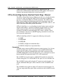
OPTera Metro 3500 NTP library
EX1541p
Guides and
Shelf Setup
TL1 Reference
Operations,
Administration
and Provisioning
Maintenance
Supporting
documentation
for the OPTera
Metro 3500
Library
Change Application
Procedures
(CAPs)
Data
Communications
Network Planning
Guide
(NTR710AM)
About the
OPTera Metro 3500
NTP Library
(323-1059-090)
Planning and
Ordering Guide
(NTRN10AN)
Network
Interworking Guide
(NTCA68CA)
OPTera Metro 3500
Network
InteroperabilityGuide
(NTRN16AA)
Installation
(323-1059-201)
Commissioning
(323-1059-210)
TL1 Reference
(323-1059-190)
System
Reconfiguration
(323-1059-224)
Performance
Monitoring
(323-1059-510)
Security and
Administration
(323-1059-302)
Network
Surveillance
(323-1059-520)
Provisioning
Synchronization
(323-1059-310)
Alarm and
Trouble Clearing
(323-1059-543)
Protection
Switching
(323-1059-311)
Bandwidth
Management
(323-1059-320)
Provisioning
Equipment and
Facilities
(323-1059-350)
System Testing
(323-1059-222)
Planning and Ordering Guide—Part 1 of 2 NTRN10AN
OPTera Metro
3000 series
DWDM Application
Guide
(NTRN12AA)
OPTera Packet Edge
System Planning
Guide
(NTRN10YK)
OPTera Packet Edge
System Network
Applications and
Management
(NTRN11YK)
OPTera Packet Edge
System User Guide
(NTN465YG)
Site Manager
Planning and
Installation Guide,
Rel 6.0
(NTNM35FA)
Rel 12.1 Standard Iss 1 Apr 2004
xii About this document
Technical support and information
For technical support and information from Nortel Networks, refer to the
following table.
Technical Assistance Service
For service-affecting problems:
For 24-hour emergency recovery or software upgrade
support, that is, for:
North America:
1-800-4NORTEL (1-800-466-7835)
• restoration of service for equipment that has been carrying
traffic and is out of service
International:
001-919-992-8300
• issues that prevent traffic protection switching
• issues that prevent completion of software upgrades
For non-service-affecting problems:
For 24-hour support on issues requiring immediate support
or for 14-hour support (8 a.m. to 10 p.m. EST) on upgrade
notification and non-urgent issues.
North America:
1-800-4NORTEL (1-800-466-7835)
Note: You require an express routing
code (ERC). To determine the ERC, see
our corporate Web site at
www.nortelnetworks.com. Click on the
Express Routing Codes link.
International:
Varies according to country. For a list of
telephone numbers, see our corporate
Web site at www.nortelnetworks.com.
Click on the Contact Us link.
Global software upgrade support:
North America:
1-800-4NORTEL (1-800-466-7835)
International:
Varies according to country. For a list of
telephone numbers, see our corporate
Web site at www.nortelnetworks.com.
Click on the Contact Us link.
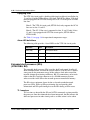
OPTera Metro 3500 Multiservice Platform
NTRN10AN
Rel 12.1 Standard Iss 1 Apr 2004
1-1
Overview
1-
Network element overview
The Nortel Networks OPTera Metro 3500 network element is a multiservice
platform offering dense wavelength division multiplexing (DWDM) with a
wide variety of services: DS1, DS3, Channelized DS3, EC-1, OC-3, OC-12,
OC-48, OC-192, 10/100BASE-T Ethernet, 100BASE-FX Ethernet, Gigabit
Ethernet and Fibre Channel.
OPTera Metro 3500 is a next generation SONET multiservice platform. It
provides full OC-192 connectivity to customer premise locations.
On the physical layer (layer 1), an OPTera Metro 3500 network can be
configured as a unidirectional path-switched ring (UPSR), a 1+1 linear
configuration, a 2-fiber bidirectional line-switched ring (BLSR), or as an
unprotected fiber optic run.
On the data link layer (layer 2), an OPTera Metro 3500 network can be
configured as an OPTera Packet Edge ring with layer 2 protection, in
accordance with Resilient Packet Rings (RPR) currently being defined by the
IEEE 802.17 working group.
OPTera Metro Release 12.0 introduced a new STX-192 switch matrix circuit
pack. The STX-192 circuit pack is a fully non-blocking STS switch matrix and
clocking module providing switching capability for 40 Gbit/s. The STX-192
provides support for 10 Gbit/s links to the line slots 11 and 12 and up to 2.5
Gbit/s links to slots 3 through 10.
For STX based configurations, the OPTera Metro 3500 is optimized for
broadband services, namely Gigabit Ethernet, Storage Area Networking, and
switched Ethernet services using Resilient Packet Ring. When configured for
STX based configurations, the platform supports full TDM services as well,
with full fill OC12 and OC48 densities. Furthermore, DS1 services are still
possible via the DS1 Service Module (DSM). For STX based configurations
where VT1.5 level management is required, a dual node configuration can be
used where by a VTX based OPTera Metro 3500 is subtended from a STX
based OPTera Metro 3500. Both nodes are managed via Site Manager, which
provides end-to-end connection management capability.
Planning and Ordering Guide—Part 1 of 2 NTRN10AN
Rel 12.1 Standard Iss 1 Apr 2004
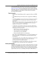
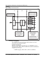
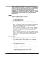
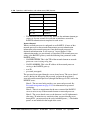
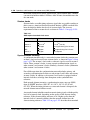
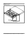
1-2 Overview
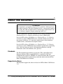
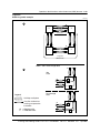
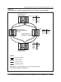
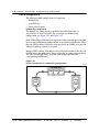
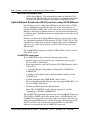
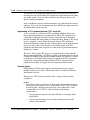
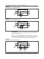
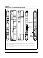
Figure 1-1
OPTera Metro 3500 slot assignments (STX-192 installed in shelf)
EX1470p
Slot 3
Slot 4
Slot 5
Slot 6
Slot 7
Slot 8
Slot 9
Slot 10
OC-48 STS or OC-192
(See Note)
STX-192
STX-192
SPx
NPx or ILAN
Empty
Slot 12
Slot 13
Slot 14
Slot 15
Slot 16
Slot 17
OC-48 STS or OC-192
(See Note)
Slot 11
Tributary
Tributary
Tributary
Slot 8
Slot 9
Slot 10
Tributary
Tributary
Slot 6
Slot 7
Tributary
Slot 5
Tributary
Tributary
Slot 4
Pwr B Pwr A
Slot 1
Slot 2
Slot 3
Empty
LOAM
LIF
I/O module slots
Note: The OC-48 STS circuit pack is a single-width circuit pack.
For VTX based configurations, the OM3500 is optimized for OC48 based
TDM and Optical Ethernet applications, supporting full densities for all TDM
services. Furthermore, with the completely non-blocking VT1.5 switch
matrix, the platform is ideally suited for hybrid digital cross connect and
add/drop multiplexer applications.
OPTera Metro 3500 Multiservice Platform
NTRN10AN
Rel 12.1 Standard Iss 1 Apr 2004
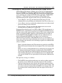
Overview 1-3
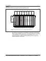
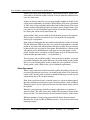
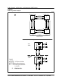
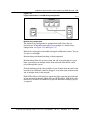
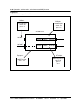
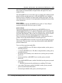
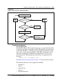
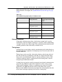
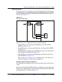
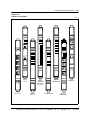
Figure 1-2
OPTera Metro 3500 slot assignments (VTX-48/VTX-48e installed in shelf)
EX1040p
Slot 3
Slot 4
Slot 5
Slot 6
Slot 7
Slot 8
Slot 9
Slot 10
PSX
Slot 17
OC-48 or OC-12
(See Note)
Slot 12
SPx
NPx or ILAN
OC-48 or OC-12
(See Note)
Slot 11
Slot 15
Slot 16
Tributary
Slot 10
VTX-48
Tributary
Tributary
Slot 8
Slot 9
Slot 14
Tributary
Tributary
Slot 6
Slot 7
VTX-48
Tributary
Slot 5
Slot 13
Tributary
Slot 4
LIF
PSC
Tributary
Slot 1
Pwr B Pwr A
LOAM
Slot 2
Slot 3
I/O module slots
Note: The OC-12 circuit pack is a single-width circuit pack.
Planning and Ordering Guide—Part 1 of 2 NTRN10AN
Rel 12.1 Standard Iss 1 Apr 2004
1-4 Overview
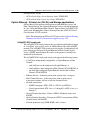
Release 12.1 features
The Release 12.1 OPTera Metro 3500 system offers the following new and
enhanced features:
• Gigabit Ethernet Drop and Continue support on 2xGigE/FC-P2P interface
• Support for extended reach (ZX) small-form factor pluggable (SFP)
This document describes the applications and functionality available in
Release 12.1. See the following chapters for more detail:
• Chapter 1, Overview, gives a high level description of what is supported in
this release.
• Chapter 2, Operation, administration, and maintenance (OAM) features,
gives a high level description of OAM&P functionality.
• Chapter 3, Hardware feature descriptions, describes both shelves and their
components.
• Chapter 4, Technical specifications (in Part 2 of this guide), lists the
technical specifications for all circuit packs and equipment.
• Chapter 5, Engineering rules (in Part 2 of this guide), lists special
engineering rules for interworking, DWDM, and Preside.
• Chapter 6, Cable and connector details (in Part 2 of this guide), lists the
cables and components used on the shelf.
• Chapter 7, Shelf mounting guidelines (in Part 2 of this guide), describes
typical installations.
• Chapter 8, Ordering information (in Part 2 of this guide), provides
procedures and tables to simplify the ordering process.
• Chapter 9, Terms and conditions (in Part 2 of this guide), provides contacts
to set up an order.
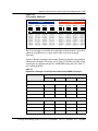
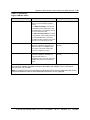
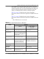
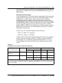
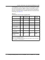
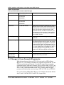
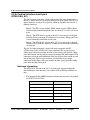
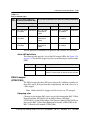
See Table 1-1 for a complete list of supported features in Release 12.1.
Table 1-1
Feature compatibility for Release 12.1
Feature
Supported on
platforms with
VTX-series
circuit packs
Supported on
platforms with
STX circuit packs
Network configurations
Bidirectional line switched ring (BLSR) (2-fiber) at OC-192 rate
No
Yes
Bidirectional line switched ring (BLSR) (2-fiber) at OC-48 rate
Yes
No
BLSR with linear spur
Yes
Yes
BLSR with subtending UPSR
Yes
Yes
OPTera Metro 3500 Multiservice Platform
NTRN10AN
Rel 12.1 Standard Iss 1 Apr 2004
Overview 1-5
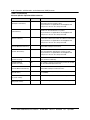
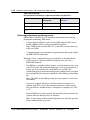
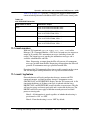
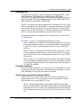
Table 1-1 (continued)
Feature compatibility for Release 12.1
Feature
Uni-directional Path switched Ring at OC3, OC-12, OC-48 or
OC-192 rates
Supported on
platforms with
VTX-series
circuit packs
Supported on
platforms with
STX circuit packs
Yes
except OC-192
Yes
Yes
Yes
Linear add/drop multiplexer OC-3, and OC-12, OC-48, and
OC-192 rates
Yes
except OC-192
Yes
except OC-192
Linear point-to-point at OC-3, OC-12, OC-48, and OC-192
rates
Yes
except OC-192
Yes
Matched nodes (on UPSR)
Yes
Yes
Mixed RPR and TDM traffic over BLSR
Yes
Yes
Mixed RPR and TDM traffic over UPSR (and above UPSR
variants)
Yes
Yes
Optical hubbing
Yes
Yes
Path-in-line (virtual ring) (across UPSR or BLSR)
Yes
Yes
RPR over BLSR (working and protection channels)
Yes
Yes
RPR over UPSR (and above UPSR variants)
Yes
Yes
Single-homed subtending rings (on UPSR)
Yes
Yes
UPSR to non-OPTera Metro 3500 BLSR interconnection
Yes
Yes
Adding a network element to an OC-48 or OC-192 BLSR
Yes
except OC-192
Yes
except OC-48
Adding a network element to a UPSR
Yes
except OC-192
Yes
Adding an OMX shelf to an in-service DWDM network
Yes
Yes
Adding an OPTera Metro 3500 network element to an OC-48
UPSR over DWDM
Yes
Yes
Adding an OPTera Metro 3500 network element to an OC-48
BLSR over DWDM
Yes
No
Converting an OC-48 UPSR to an OC-48 UPSR over DWDM
Yes
Yes
Converting an OC-48 BLSR to an OC-48 BLSR over DWDM
Yes
No
Dual-homed subtending rings (on UPSR)
In-service reconfigurations
Planning and Ordering Guide—Part 1 of 2 NTRN10AN
Rel 12.1 Standard Iss 1 Apr 2004
1-6 Overview
Table 1-1 (continued)
Feature compatibility for Release 12.1
Feature
Supported on
platforms with
VTX-series
circuit packs
Supported on
platforms with
STX circuit packs
Converting an OC-48 linear point-to-point network to an
OC-48 linear point-to-point network over DWDM
Yes
Yes
Adding an OPTera Metro 3500 network element to an OC-192
UPSR over DWDM
No
Yes
Converting an OC-192 UPSR to an OC-192 UPSR over
DWDM
No
Yes
Converting an OC-192 linear point-to-point network to an
OC-192 linear point-to-point network over DWDM
No
Yes
Yes
See Note 3
Yes
See Note 3
Converting a 1+1 linear point-to-point configuration to a
2-node UPSR
Yes
Yes
Converting a 2-node UPSR to a 1+1 linear point-to-point
configuration
Yes
Yes
Moving a synchronization boundary
Yes
Yes
Yes
except OC-192
Yes
except OC-48
Removing a network element from a UPSR
Yes
Yes
Removing an OPTera Metro 3500 network element from an
OC-48 BLSR over DWDM
Yes
No
Removing an OPTera Metro 3500 network element from an
OC-48 UPSR over DWDM
Yes
Yes
Replacing a DS3x3 mapper with a DS3x12 / DS3x12e mapper
Yes
Yes
Replacing an EC-1x3 circuit pack with an EC-1x12 circuit pack
Yes
Yes
Replacing the ILAN circuit pack with a network processor
Yes
Yes
Replacing the network processor with an ILAN circuit pack
Yes
Yes
Upgrading a fiber span from an OC-3 to an OC-12 rate
(See Note 2)
Yes
Yes
Upgrading a fiber span from an OC-12 to an OC-48 rate
(See Note 2)
Yes
Yes
Converting a UPSR to a BLSR
Removing a network element from an OC-48 or OC-192 BLSR
OPTera Metro 3500 Multiservice Platform
NTRN10AN
Rel 12.1 Standard Iss 1 Apr 2004
Overview 1-7
Table 1-1 (continued)
Feature compatibility for Release 12.1
Feature
Supported on
platforms with
VTX-series
circuit packs
Supported on
platforms with
STX circuit packs
Upgrading a fiber span from an OC-48 to an OC-192 rate
No
Yes
See Note 3
Converting a VT-assigned BLSR connection to a Full VT
BLSR connection
Yes
No
Converting a Full VT BLSR connection to a VT-assigned
BLSR connection
Yes
No
DS1
Yes
Yes
DS3
Yes
Yes
DS3 (Channelized)
Yes
No
EC-1
Yes
Yes
OC-3
Yes
Yes
OC-12
Yes
Yes
OC-48
Yes
Yes
OC-192
No
Yes
Optical Ethernet - Private Line service using 10/100 Ethernet
Yes
Yes
Optical Ethernet - Private Line using Gigabit Ethernet
Yes
Yes
full rate support
OPTera Packet Edge System
See:
Yes
Yes
Resilient Packet Ring (RPR)
Yes
Yes
Storage Network (Fibre Channel (FC100) & FICON)
Yes
Yes
Test Access Electrical and Optical TAPS (monitor and split
states)
Yes
Yes
Services
• OPTera Metro 3000 OPTera Packet Edge System User Guide
(NTN465YG)
• OPTera Packet Edge System Planning Guide (NTRN10YK)
• OPTera Packet Edge System Network Applications and
Management (NTRN11YK)
Hardware (See Note 2)
Planning and Ordering Guide—Part 1 of 2 NTRN10AN
Rel 12.1 Standard Iss 1 Apr 2004
1-8 Overview
Table 1-1 (continued)
Feature compatibility for Release 12.1
Feature
Supported on
platforms with
VTX-series
circuit packs
Supported on
platforms with
STX circuit packs
OPTera Metro 3500 Shelf Assembly (NTN476AA)
Yes
Yes
See Note 4
OPTera Metro 3500 Shelf Assembly (NTN476DA)
Yes
Yes
OPTera Metro 3500 Universal Shelf Assembly (NTN476AH)
Yes
Yes
2x100BT-P2P circuit pack (NTN433AA)
Yes
Yes
4x100FX (NTN4333EA, NTN433FA)
Yes
Yes
4x100BT (NTN433BB)
Yes
Yes
2x1000SX (NTN438AA)
Yes
Yes
2x1000LX (NTN438BA)
Yes
Yes
2xGigE/FC-P2P (NTN438DA)
Yes
Yes
1000-BaseSX 850 nm SFP (NTTP51AA)
Yes
Yes
1000-BaseLX 1310 nm SFP (NTTP51BD)
Yes
Yes
1000-BaseZX 1550 nm SFP (NTTP51DZ)
Yes
Yes
DS1 mapper (1:N protection)
Yes
No
DS1 service module (DSM) (up to 12 protected or unprotected
DSM on an NE)
Yes
Yes
DS3 mapper
See Note 5
No
No
DS3VTx12 mapper
Yes
No
DS3x12 mapper (1+1 protection)
Yes
Yes
DS3x12e mapper (1+1 protection)
Yes
Yes
DS3x3 mapper (1+1 protection) (NTN437AA)
Yes
Yes
DSM DS1x84 termination module (TM)
Yes
Yes
EC-1 circuit pack
See Note 5
No
No
EC-1x12 circuit pack (1+1 protection)
Yes
Yes
EC-1x3 circuit pack (1+1 protection) (NTN436AA)
Yes
Yes
OPTera Metro 3500 Multiservice Platform
NTRN10AN
Rel 12.1 Standard Iss 1 Apr 2004
Overview 1-9
Table 1-1 (continued)
Feature compatibility for Release 12.1
Feature
Supported on
platforms with
VTX-series
circuit packs
Supported on
platforms with
STX circuit packs
OC-3 circuit pack in slots 11 and 12 (UPSR, 1+1 linear
point-to-point and 1+1 linear ADM)
No
No
OC-3 circuit pack in slots 3 through 10 (UPSR, 1+1 linear
point-to-point and 1+1 linear ADM)
Yes
Yes
OC-3x4 circuit pack in slots 11 and 12 (UPSR, 1+1 linear
point-to-point and 1+1 linear ADM)
No
No
OC-3x4 circuit pack in slots 3 through 10 (UPSR, 1+1 linear
point-to-point and 1+1 linear ADM)
Yes
Yes
OC-12 circuit pack in slots 11 and 12 (UPSR, 1+1 linear
point-to-point and 1+1 linear ADM)
Yes
No
OC-12 circuit pack in slots 3 through 10 (UPSR, 1+1 linear
point-to-point and 1+1 linear ADM)
Yes
Yes
OC-12x4 STS circuit pack in slots 11 and 12 (UPSR, 1+1
linear point-to-point and 1+1 linear ADM)
No
No
OC-12x4 STS circuit pack in slots 3 through 10 (UPSR, 1+1
linear point-to-point and 1+1 linear ADM)
No
Yes
OC-48 circuit pack in slots 11 and 12 (BLSR, UPSR, 1+1 linear
point-to-point)
Yes
No
OC-48 circuit pack in slots 3 through 10 (UPSR, 1+1 linear
point-to-point)
No
No
OC-48 STS circuit pack in slots 3 to 12 (UPSR, 1+1 linear
point-to-point)
No
Yes
OC-48 DWDM circuit pack in slots 11 and 12 (BLSR, UPSR,
1+1 linear point-to-point)
Yes
No
OC-48 DWDM circuit pack in slots 3 through 10 (UPSR, 1+1
linear point-to-point)
No
No
OC-192 circuit pack in slots 11 and 12 (BLSR, UPSR, 1+1
linear point-to-point)
No
Yes
OC-192 circuit pack in slots 3 through 10 (UPSR, 1+1 linear
point-to-point)
No
No
STM-0 optical interface (1+1 protection) (in J-SDH mode)
See Note 5
No
No
Planning and Ordering Guide—Part 1 of 2 NTRN10AN
Rel 12.1 Standard Iss 1 Apr 2004
1-10 Overview
Table 1-1 (continued)
Feature compatibility for Release 12.1
Feature
Supported on
platforms with
VTX-series
circuit packs
Supported on
platforms with
STX circuit packs
STM-1 optical interface (1+1 protection) (in J-SDH mode)
See Note 5
No
No
STM-1x4 optical interface (in J-SDH mode)
(in Slots 3 through 10)
Yes
Yes
Intershelf LAN (ILAN) circuit pack
Yes
Yes
Network Processor circuit pack (NP circuit pack) (NTN422AA)
See Note 5
No
No
Network Processor circuit pack - extended (NPx circuit pack)
(NTN424Bx)
Yes
Yes
Shelf Processor circuit pack - terminal (SP circuit pack)
(NTN420AA)
See Note 5
No
No
Shelf Processor circuit pack - enhanced (SPe circuit pack)
(NTN421BA)
See Note 5
No
No
Shelf Processor circuit pack - extended (SPx circuit pack)
(NTN423Bx)
Yes
Yes
OMX shelf
Yes
Yes
DS1 line and path
Yes
Yes
See Note 6
DS1e far-end line and path
Yes
Yes
See Note 6
DS1e far-end line and path with F bit generation
Yes
Yes
See Note 6
DS3 line and path
Yes
Yes
DS3/VT line and path
Yes
No
EC-1 section and line
Yes
Yes
Path PMs on DS3x12e circuit pack
Yes
Yes
OC-12 section and line
Yes
Yes
OC-3 section and line
Yes
Yes
Performance monitoring
OPTera Metro 3500 Multiservice Platform
NTRN10AN
Rel 12.1 Standard Iss 1 Apr 2004
Overview 1-11
Table 1-1 (continued)
Feature compatibility for Release 12.1
Feature
Supported on
platforms with
VTX-series
circuit packs
Supported on
platforms with
STX circuit packs
OC-48 section and line
Yes
Yes
OC-192 section and line
No
Yes
Physical performance monitoring for OC-48 DWDM ER and
ELR circuit pack-receiver
Yes
No
Physical performance monitoring for OC-48 STS and OC-192
circuit pack-receiver
No
Yes
STM-0 section and line (in J-SDH mode)
See Note 5
No
No
STM-1 section and line (in J-SDH mode)
See Note 5
Yes
Yes
STS-1 path
Yes
Yes
STS-3c path
Yes
Yes
STS-12c path
See Note 7
Yes
Yes
STS-24c path
No
Yes
STS48c path
No
Yes
Ethernet Operational Measurements
Yes
Yes
User account creation
Yes
Yes
Network element / network processor naming
Yes
Yes
Time zone, date and time setting
Yes
Yes
Maintenance and updating of accounts and network element
parameters
Yes
Yes
Intrusion attempt handling on the SPx and NPx
Yes
Yes
Password management on the SPx and NPx
Yes
Yes
Customer managed networks on the SPx and NPx
Yes
Yes
Security log / audit trail
Yes
Yes
Multiple authentication methods
Yes
Yes
Security and administration
Planning and Ordering Guide—Part 1 of 2 NTRN10AN
Rel 12.1 Standard Iss 1 Apr 2004
1-12 Overview
Table 1-1 (continued)
Feature compatibility for Release 12.1
Feature
Supported on
platforms with
VTX-series
circuit packs
Supported on
platforms with
STX circuit packs
Challenge / Response authentication
Yes
Yes
Centralized authentication through a RADIUS server
Yes
Yes
Third span of control surveillance
Yes
Yes
General Broadcast tool
Yes
Yes
In-service traffic rollover for TDM traffic
Yes
Yes
In-service traffic rollover for RPR traffic
No
No
STS-1 traffic
Yes
Yes
STS-3c traffic
Yes
Yes
STS-12c traffic
Yes
Yes
STS-24c traffic
No
Yes
STS-48c traffic
No
Yes
STS-48c, STS24c, STS-12c, STS-3c, STS-1 time slot
assignment (TSA) on pass-through nodes on BLSR
Yes
except STS24c &
STS-48c
Yes
STS-48c, STS-24c, STS-12c, STS-3c, STS-1, VT1.5
broadcast on 1+1 linear, UPSR
Yes
except STS24c &
STS-48c
Yes
except VT1.5
STS-48c, STS-24c, STS-12c, STS-3c, STS-1, VT1.5
drop-and-continue on 1+1 linear, UPSR
Yes
except STS24c &
STS-48c
Yes
except VT1.5
STS48c, STS-24c, STS-12c, STS-3c, STS-1, VT1.5
drop-and-continue on BLSR
No
No
STS-48c, STS-24c, STS-12c, STS-3c, STS-1, VT1.5
hairpinning
Yes
except STS24c &
STS-48c
Yes
VT1.5
STS-48c, STS-24c, STS-12c,STS-3c, STS-1, VT1.5 time slot
assignment (TSA) on 1+1 linear, UPSR
Yes
except STS24c &
STS-48c
Yes
VT1.5
STS-48c, STS-24c, STS-12c, STS-3c, STS-1, VT1.5 time slot
assignment (TSA) on add/drop nodes on BLSR
Yes
except STS-48c
Yes
VT1.5
Bandwidth management
OPTera Metro 3500 Multiservice Platform
NTRN10AN
Rel 12.1 Standard Iss 1 Apr 2004
Overview 1-13
Table 1-1 (continued)
Feature compatibility for Release 12.1
Feature
Supported on
platforms with
VTX-series
circuit packs
Supported on
platforms with
STX circuit packs
STS-48c, STS-24c, STS-12c, STS-3c, STS-1, VT1.5 time slot
interchange (TSI) on 1+1 linear, UPSR
Yes
except STS24c &
STS-48c
Yes
VT1.5
STS-48c, STS-24c, STS-12c, STS-3c, STS-1, VT1.5 time slot
interchange (TSI) on BLSR
Yes
except STS24c &
STS-48c
Yes
VT1.5
TU11, TU21, AU32, AU4 cross-connects (in J-SDH mode)
Yes
Yes
supports AU32
and AU4
VT1.5/ time slot assignment (TSA) on pass-through nodes on
BLSR
Yes
No
VT6 cross-connects (in J-SDH mode)
Yes
No
6.312-MHz clock (in J-SDH mode)
Yes
Yes
Alarm provisioning
Yes
Yes
Composite clock timing (in J-SDH mode)
Yes
Yes
Consolidated load
Yes
Yes
DS1 ESF BITS synchronization status messaging
Yes
Yes
DS1 automatic in-service (AINS)
Yes
Yes
DS1 loopback
Yes
No
DS3 automatic in-service (AINS) on T3 facilities
Yes
Yes
DS3 loopback
Yes
Yes
DS3/VT automatic in-service (AINS) on T3 facilities
Yes
No
External building-integrated timing supply (BITS) input/output
Yes
Yes
Full TARP
Yes
Yes
Hitless timing reference switching
Yes
Yes
Independent synchronization and bandwidth management
switching
Yes
Yes
Mixed tributaries
Yes
Yes
Miscellaneous
Planning and Ordering Guide—Part 1 of 2 NTRN10AN
Rel 12.1 Standard Iss 1 Apr 2004
1-14 Overview
Table 1-1 (continued)
Feature compatibility for Release 12.1
Feature
Supported on
platforms with
VTX-series
circuit packs
Supported on
platforms with
STX circuit packs
NP/SP version checking
Yes
Yes
OC-3 1+1 high speed exerciser
Yes
Yes
OC-12 1+1 high-speed exerciser
Yes
Yes
OC-48 1+1 high-speed exerciser
Yes
Yes
OC-192 1+1 high-speed exerciser
No
Yes
Optical Facility loopbacks for OC-3, OC-12, EC1x12, OC-3x4,
STM-1x4, OC-12x4 STS, OC-48, OC-48 STS, OC-192,
2xGigE/FC-P2P
Yes
except OC-192
Yes
Optical Terminal loopbacks for OC-3, OC-12, EC1x12,
OC-3x4, STM-1x4, OC-12x4 STS, OC-48, OC-48 STS,
OC-192, 2xGigE/FC-P2P
Yes
except OC-192
Yes
except OC-192
OSI 7 layer
Yes
Yes
Path trace
Yes
Yes
Site Manager Rel 6.0.1
See Note 8
Yes
Yes
Remote save and restore
Yes
Yes
S1 byte synchronization status messaging
Yes
Yes
Section trace
Yes
Yes
Shelf timing (internal, line/loop, tributary, external)
Yes
Yes
Stratum 3 internal clock
Yes
Yes
SP spare management enhancements
Yes
Yes
SSbit functionality at OC-3, OC-12, OC-48 and OC-192 rates
Yes
except OC-192
Yes
STS-1 path trace for DS3, OC-3, OC-12, OC-48 and OC-192
Yes
except OC-192
Yes
See Note 9
OPTera Metro 3500 Multiservice Platform
NTRN10AN
Rel 12.1 Standard Iss 1 Apr 2004
Overview 1-15
Table 1-1 (continued)
Feature compatibility for Release 12.1
Feature
Supported on
platforms with
VTX-series
circuit packs
Supported on
platforms with
STX circuit packs
Time of day synchronization
Yes
Yes
VT1.5 group alarm
Yes
No
Note 1: See Table 1-2 on page 1-16 for a list of optical circuit packs supported by each STX and
VTX-series circuit packs.
Note 2: See Table 1-2 on page 1-16 for a list of optical circuit packs supported by each STX and
VTX-series circuit packs.
Note 3: This is an out-of service procedure.
Note 4: The OPTera Metro 3500 Shelf assembly (NTN476AA) must be upgraded using power module
and cooling upgrade kit (NTN458MW) to support OC-192 optical interfaces.
Note 5: This interface is below the hardware baseline for OPTera Metro Release 12.1 and it is not
supported.
Note 6: DS1 PMs are available through DSM connected to OPTera Metro 3500 equipped with STX-192
circuit pack.
Note 7: Supported on all new Release 12.1 circuit packs (OC12x4 STS, OC-48 STS and OC-192)
along with all OC-48 circuit packs and selected OC-12 circuit packs (NTN404JA, NTN404KA,
NTN404LA, NTN404MA).
Note 8: Site Manager Release 6.0.1 is backward compatible to the following releases:
— OPTera Metro 3500 Releases 10.1, 10.3, 10.31, 11.01, 11.02, 12.0 and 12.1
— OPTera Metro 3300/3400 Releases 9.12, 11.11 and 11.12
— OPTera Metro 3100 Release 4.01 and 4.02
Note 9: For OPTera Metro 3500 equipped with STX-192 circuit packs (STS-managed), path trace must
be monitored on the path terminating equipment such as DSM module, DS3, 2x100BT- P2P,
2xGigGE/FC circuit packs.
Planning and Ordering Guide—Part 1 of 2 NTRN10AN
Rel 12.1 Standard Iss 1 Apr 2004
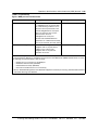
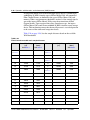
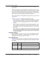
1-16 Overview
Release 12.1 Hardware Compatibility Matrix
For a list of supported electrical and optical interfaces by STX and VTX-series
circuit packs in Release 12.1, see Table 1-2.
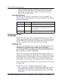
Table 1-2
Hardware Compatibility Matrix for Release 12.1
Card Type
OC-192
Supported on Supported on
platform with platforms with
STX- 192
VTX-series
circuit packs circuit packs
Yes
No
Notes
• Dual slot circuit packs
supported in slots 11
and 12.
• Supported only with
STX-192 circuit pack.
OC-48 STS
Yes
No
• Single slot circuit packs
supported in slots 3 to
12.
• Supported only with
STX-192 circuit pack.
OC-48
No
Yes
• Dual slot circuit packs
supported in slots 11
and 12.
• Supported only with
VTX-series circuit pack.
OC-12x4 STS
Yes
No
• Single slot circuit packs
supported in slots 3
through 10.
• Supported with STX-192
circuit pack.
OC-12
Yes
Yes
• Single slot circuit packs
not supported in slots 11
and 12 with STX-192 or
VTX-48 circuit packs.
• Single slot circuit packs
supported in slots 3
through 10 with STX-192
or VTX-48 circuit packs.
• Single slot circuit packs
supported in slots 3
through 12 with VTX-48e
circuit pack.
OPTera Metro 3500 Multiservice Platform
NTRN10AN
Rel 12.1 Standard Iss 1 Apr 2004
Overview 1-17
Table 1-2 (continued)
Hardware Compatibility Matrix for Release 12.1
Card Type
Supported on Supported on
platform with platforms with
STX- 192
VTX-series
circuit packs circuit packs
Notes
OC-3x4
Yes
Yes
Single slot circuit packs
supported in slots 3
through 10.
OC-3
Yes
Yes
• Single slot circuit packs
supported in slots 3
through 10.
STM-1x4
Yes
Yes
• Single slot circuit packs
supported in slots 3
through 10.
2xGigE/FC-P2P
Yes
Yes
• Single slot circuit pack
supported in slots 3
through 10.
• Maximum bandwidth of
12xSTS1 per card when
equipped with
VTX-series circuit packs.
• Maximum bandwidth of
2xSTS24 per card when
equipped with STX-192
circuit packs.
2xGigE (OPE)
Yes
Yes
• Dual slot circuit pack
supported in slots 3
through 10.
• Maximum bandwidth
assignable to a RPR is
STS12c with both
VTX-series and
STX-192 circuit packs.
4x100FX (OPE)
Yes
Yes
• Single slot circuit pack
supported in slots 3
through 10.
• Maximum bandwidth
assignable to a RPR is
STS12c with both
VTX-series and
STX-192 circuit packs.
Planning and Ordering Guide—Part 1 of 2 NTRN10AN
Rel 12.1 Standard Iss 1 Apr 2004
1-18 Overview
Table 1-2 (continued)
Hardware Compatibility Matrix for Release 12.1
Card Type
4x100BT(OPE)
Supported on Supported on
platform with platforms with
STX- 192
VTX-series
circuit packs circuit packs
Yes
Yes
Notes
• Single slot circuit pack
supported in slots 3
through 10.
• Maximum bandwidth
assignable to a RPR is
STS12c with both
VTX-series and
STX-192 circuit packs.
2x100BT-P2P
(Private Lines)
Yes
Yes
• Single slot circuit pack
supported in slots 3
through 10.
EC-1x12
Yes
Yes
• Single slot circuit pack
supported in slots 3
through 10.
DS3x12
Yes
Yes
• Single slot circuit pack
supported in slots 3
through 10.
EC-1x3
Yes
Yes
• Single slot circuit pack
supported in slots 3
through 10.
DS3VTx12
No
Yes
• Single slot circuit pack
supported in slots 3
through 10.
DS3x3
Yes
Yes
• Single slot circuit pack
supported in slots 3
through 10.
12xDS1
No
Yes
• Single slot circuit pack
supported in slots 3
through 10.
84xDS1 (DSM)
Yes
Yes
• Support for 12 DSM per
shelf.
• DSM is only STS-1
managed with STX-192.
OPTera Metro 3500 Multiservice Platform
NTRN10AN
Rel 12.1 Standard Iss 1 Apr 2004
Overview 1-19
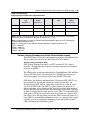
Supported configurations
For network element configurations supported in Release 12.1, see Table 1-3
through Table 1-6.
Table 1-3 provides a summary of all network topologies supported when main
optical interfaces (slots 11 and 12) are configured as BLSR.
Table 1-4 provides a summary of all network topologies supported when main
optical interfaces (slots 11 and 12) are configured as UPSR.
Table 1-5 provides a summary of all network topologies supported when main
optical interfaces (slots 11 and 12) are configured as Linear point-to-point or
Linear ADM
Table 1-6 provides a summary of various network topologies supported on the
OPTera Metro 3500,
Planning and Ordering Guide—Part 1 of 2 NTRN10AN
Rel 12.1 Standard Iss 1 Apr 2004
1-20 Overview
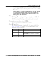
Table 1-3
Summary of network topology supported - main optical interfaces configured as BLSR
Shelf platform
(VTX or STX)
Line rate of BLSR
optical interfaces
(Slots 11 & 12)
Supported
subtending
configurations
Line rate of subtending
configurations
(Slots 3 - 10)
OC-12
Linear Spur
VTX-48
OC-48
(requires dual slot circuit
pack)
OC-3
OC-12
UPSR
OC-3
OC-12
Linear Spur
VTX-48e
OC-48
(requires dual slot circuit
pack)
OC-3
OC-12
UPSR
OC-3
OC-48
(requires OC-48 STS circuit
packs)
Linear Spur
OC-12
OC-3
STX-192
OC-48
(requires OC-48 STS circuit
packs)
OC-192
UPSR
OC-12
OC-3
OPTera Metro 3500 Multiservice Platform
NTRN10AN
Rel 12.1 Standard Iss 1 Apr 2004
Overview 1-21
Table 1-4
Summary of network topology supported - main optical interfaces configured as UPSR
Shelf platform
(VTX or STX)
Line rate of UPSR
optical interfaces
(slots 11 & 12)
Supported
subtending
configurations
Line rate of subtending
configurations
(Slot 3 - 10)
OC-12
Linear Spur
VTX-48
OC-48
(requires dual slot circuit
pack)
OC-3
OC-12
UPSR
OC-3
OC-12
Linear Spur
OC-48
(requires dual slot circuit
pack)
OC-3
OC-12
UPSR
OC-3
VTX-48e
OC-12
Linear Spur
OC-12
OC-3
OC-12
UPSR
Planning and Ordering Guide—Part 1 of 2 NTRN10AN
OC-3
Rel 12.1 Standard Iss 1 Apr 2004
1-22 Overview
Table 1-4 (continued)
Summary of network topology supported - main optical interfaces configured as UPSR
Shelf platform
(VTX or STX)
Line rate of UPSR
optical interfaces
(slots 11 & 12)
Supported
subtending
configurations
Line rate of subtending
configurations
(Slot 3 - 10)
OC-48
(requires OC-48 STS circuit
pack)
Linear Spur
OC-12
OC-3
OC-192
OC-48
(requires OC-48 STS circuit
pack)
UPSR
OC-12
OC-3
STX-192
Linear Spur
OC-48
(requires OC-48 STS circuit
pack)
OC-12
OC-48
(requires OC-48 STS
circuit pack)
OC-3
UPSR
OC-48
(requires OC-48 STS circuit
pack)
OC-12
OC-3
Table 1-5
Summary of network topology supported - main optical interfaces configured as Linear (pt-to-pt
or ADM)
Shelf platform
(VTX or STX)
VTX-48
Line rate of Linear
optical interfaces
(Slots 11 & 12)
Supported
subtending
configurations
Line rate of subtending
configurations
(Slots 3 - 10)
Linear (pt-to-pt or
ADM chain)
OC-12
OC-48
(requires dual slot circuit
pack)
OPTera Metro 3500 Multiservice Platform
NTRN10AN
OC-3
OC-12
UPSR
OC-3
Rel 12.1 Standard Iss 1 Apr 2004
Overview 1-23
Table 1-5 (continued)
Summary of network topology supported - main optical interfaces configured as Linear (pt-to-pt
or ADM)
Shelf platform
(VTX or STX)
Line rate of Linear
optical interfaces
(Slots 11 & 12)
OC-48
(requires dual slot circuit
pack)
VTX-48e
Supported
subtending
configurations
Line rate of subtending
configurations
(Slots 3 - 10)
Linear (pt-to-pt or
ADM chain)
OC-12
OC-3
OC-12
UPSR
OC-3
Linear (pt-to-pt or
ADM chain)
OC-12
OC-12
OC-3
OC-12
UPSR
OC-3
Linear (pt-to-pt or
ADM chain)
OC-48
(requires OC-48 STS circuit
pack)
OC-12
OC-3
OC-192
OC-48
(requires OC-48 STS circuit
pack)
UPSR
OC-12
OC-3
STX-192
Linear (pt-to-pt or
ADM chain)
OC-48
(requires OC-48 STS
circuit pack)
OC-48
(requires OC-48 STS circuit
pack)
OC-12
OC-3
OC-48
(requires OC-48 STS circuit
pack)
UPSR
OC-12
OC-3
Planning and Ordering Guide—Part 1 of 2 NTRN10AN
Rel 12.1 Standard Iss 1 Apr 2004
1-24 Overview
Table 1-6
Summary of network topology line rates
Network topology
Supported on platforms
with VTX-series circuit
packs
Supported on platforms
with STX circuit packs
OC-3
OC-12
OC-48
OC-48
OC-192
Dual-homed subtending rings (UPSR)
Yes
Yes
Yes
Yes
Yes
Linear add/drop multiplexer
Yes
Yes
Yes
Yes
No
Linear point-to-point
Yes
Yes
Yes
Yes
Yes
Matched nodes (UPSR)
Yes
Yes
Yes
Yes
Yes
See Note 1
Mixed RPR and TDM traffic over BLSR
No
No
Yes
No
See Note 2
Yes
Mixed RPR and TDM traffic over UPSR
Yes
Yes
Yes
Yes
Yes
Optical hubbing
Yes
Yes
Yes
Yes
Yes
Path-in-line ring (virtual ring) (on BLSR)
No
No
Yes
No
See Note 2
Yes
Full VT BLSR
No
No
Yes
No
See Note 3
No
See Note 3
VT-assigned BLSR
No
No
Yes
No
See Note 3
No
See Note 3
STS-1 assigned BLSR
No
No
Yes
No
See Note 2
Yes
Path-in-line ring (virtual ring) (on UPSR)
Yes
Yes
Yes
Yes
Yes
RPR over BLSR (working and protection
channels)
No
No
Yes
No
See Note 2
Yes
RPR over UPSR
Yes
Yes
Yes
Yes
Yes
Single-homed subtending rings (UPSR)
Yes
Yes
Yes
Yes
Yes
UPSR
Yes
Yes
Yes
Yes
Yes
UPSR to non-OPTera Metro 3500 BLSR
interconnection
Yes
Yes
Yes
Yes
Yes
Note 1: If interconnecting two mixed traffic rings (VT and STS traffic), STS traffic must be used at the
gateway network element.
Note 2: OC-48 BLSR is supported on OPTera Metro 3500 equipped with VTX-series switched matrix
in slots 13 and 14.
Note 3: STX-192 circuit pack is an STS-managed switch matrix in slots 13 and 14.
OPTera Metro 3500 Multiservice Platform
NTRN10AN
Rel 12.1 Standard Iss 1 Apr 2004
Overview 1-25
The following DWDM wavelength topologies are also supported:
• meshed ring
• hubbed ring
• point-to-point
Interworking
•
OPTera Metro 5000-series Multiservice Platform (Release 6.1)
Note: UPSR, BLSR, and 1+1 linear protection schemes for OPTera Metro
3500 signals pass through OPTera Metro 5000 network segments
transparently. Logical UPSRs, BLSRs and 1+1 linear configurations are
possible across both OPTera Metro 3000 and 5000 DWDM networks.
— OPTera Metro 3500 Gigabit Ethernet and Fibre Channel services (GFP
mapped) to OPTera Metro 5200 and OPTera Metro 5100.
— OPTera Metro 3500 aggregated signal (Gigabit Ethernet, OC-3,
OC-12, OC-48) to OPTera Metro 5000 OCI to OPTera Metro 5000
DWDM network.
— OPTera Metro 3500 DWDM to OPTera Metro 5000 DWDM
— OPTera Metro 3500 DWDM to OPTera Metro 5200 OFA to OPTera
Metro 3500 DWDM
— OPTera Metro 3500 DWDM to OPTera Metro 5200 OFA to OC-48
Classic DWDM
•
•
•
OPTera Connect DX (Release 5 and higher):
— 1+1 linear point-to-point at OC-3, OC-12, OC-48 and OC-192 line
rates
— UPSR at OC-3, OC-12 and OC-48 line rates
— BLSR at OC-48 and OC-192 line rates
— virtual ring at OC-3, OC-12 and OC-48 line rates
Optical Cross Connect HDX (formally OPTera Connect HDX) (Release
2):
— 1+1 linear point-to-point at OC-3, OC-12, OC-48 and OC-192 line
rates
— BLSR at OC-48 and OC-192 line rates
Optical Cross Connect HDXc (formally OPTera Connect HDXc)
(Release 2.1):
— 1+1 linear point-to-point at OC-3, OC-12, OC-48 and OC-192 line
rates
— BLSR at OC-48 and OC-192 line rates
Planning and Ordering Guide—Part 1 of 2 NTRN10AN
Rel 12.1 Standard Iss 1 Apr 2004
1-26 Overview
•
•
•
•
•
TransportNode OC-12 TBM (Release 14):
— 1+1 linear point-to-point at OC-3, and OC-12 line rates
— virtual ring at OC-3 line rate
TransportNode OC-48 (Release 17):
— 1+1 linear point-to-point at OC-3, OC-12 and OC-48 line rates
— virtual ring at OC-3 and OC-12 line rates
— matched nodes at STS-1, OC-3 and OC-12 line rates
— OC-48 Regenerator
— BLSR at OC-48 line rate
OPTera Long Haul 1600 (Release 7 and higher):
— OC-48 and OC-192 line rates
TransportNode OC-192 (Release 7.0):
— 1+1 linear point-to-point at OC-3, OC-12, OC-48 and OC-192 line
rates
— virtual ring at OC-3, OC-12 and OC-48 line rates
for OPE interworking, see OPTera Packet Edge System Planning Guide
(NTRN10YK).
Note: For Nortel Networks interworking and multi-vendor network
scenarios, DCC interoperability can be achieved with the appropriate
provisioning. See Optical Networks Data Communications Network
Planning Guide, NTR710AM.
Supported upgrade paths
Supported upgrade paths for OPTera Metro 3500 Release 12.1 are 10.1, 10.3,
10.31, 11.01, 11.02 and 12.0.
OPTera Metro 3500 Multiservice Platform
NTRN10AN
Rel 12.1 Standard Iss 1 Apr 2004
2-1
Operation, administration, and
maintenance (OAM) features
2-
This section describes the operations, administration, and maintenance (OAM)
features of Release 12.1 software.
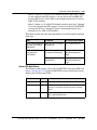
Table 2-1 lists new OAM features in Release 12.1, and Table 2-2 lists OAM
features Release 12.1 continues to support.
Table 2-1
New or enhanced OAM features in OPTera Metro 3500 Release 12.1
Feature
Page
Gigabit Ethernet Drop and Continue
2-3
Table 2-2
OPTera Metro 3500 OAM features
Feature
Page
Alarm provisioning
2-5
Bandwidth management
2-7
BLSR networks (2-fiber)
2-10
Channelized DS3 service (DS3VTx12 mapper)
2-44
Common Language Location Identifier
2-44
Connection ID
2-45
Consolidated load
2-45
Dense wavelength division multiplexing (DWDM)
2-46
Facility attributes
2-54
Loopbacks
2-54
Network surveillance
2-58
OPTera Packet Edge System (Resilient Packet Ring) - Ethernet 2-62
Planning and Ordering Guide—Part 1 of 2 NTRN10AN
Rel 12.1 Standard Iss 1 Apr 2004
2-2 Operation, administration, and maintenance (OAM) features
Table 2-2 (continued)
OPTera Metro 3500 OAM features
Feature
Page
Optical Ethernet / Layer 2 (OE/L2) on OPTera Packet Edge
System
2-64
Optical Ethernet-Private Line (OE-PL) services using 10/100
Ethernet
2-66
Optical Ethernet-Private Line (OE-PL) service using 2x1000
SX/LX OPE circuit packs
2-71
Optical Ethernet - Private Line (OE-PL) and Storage applications 2-73
Optical interoperability of OPTera Metro 3500
2-102
Performance monitoring
2-102
Site Manager support
2-116
Preside Applications Platform and Multiservice MOA support
2-117
Protection switching
2-118
Security and administration
2-122
STS Managed DSM
2-142
Support for 12 DSM
2-146
Synchronization
2-146
Test Access
2-160
Time of day synchronization
2-169
TL1 Changes to Cross Connect AID parameter
2-172
TL1 event exerciser
2-173
TL1 event / log feature
2-173
Topology enhancements
2-175
VT management option on STX equipped OPTera Metro 3500
2-175
OPTera Metro 3500 Multiservice Platform
NTRN10AN
Rel 12.1 Standard Iss 1 Apr 2004
Operation, administration, and maintenance (OAM) features 2-3
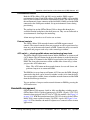
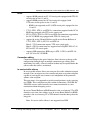
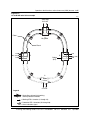
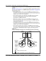
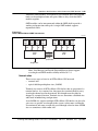
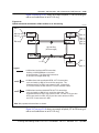
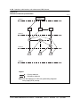
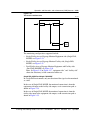
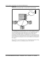
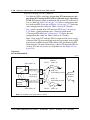
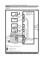
Gigabit Ethernet Drop and Continue
OPTera Metro 3500 Release 12.1, extends its Unidirectional Multi-Node Drop
and Continue capability to support unidirectional Gigabit Ethernet (GE)
traffic. Unidirectional Multi-Node Drop and Continue provides the ability to
drop a time slot, either SONET contiguous (STS-1, STS-3c, STS-12c and
STS24c) or Virtual concatenation (STS-1-nv, n = 1 through 21 or STS-3c-nv,
n = 1 through 7), at a single or on a continuing series of nodes in an UPSR ring
or linear chain using a single timeslot on the ring or the linear chain. Gigabit
Ethernet unidirectional drop and continue connections are supported by the
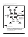
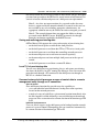
2xGigE/FC-P2P interface for UPSR rings. Figure 2-1 on page 2-4, illustrates
an application where a video signal is inserted on a 2xGigE/FC-P2P interface
at one node and dropped on 2xGigE/FC-P2P interfaces at 5 subsequent nodes
using a unidirectional CCAT or VCAT timeslot(s).
Planning and Ordering Guide—Part 1 of 2 NTRN10AN
Rel 12.1 Standard Iss 1 Apr 2004
2-4 Operation, administration, and maintenance (OAM) features
Figure 2-1
Gigabit Ethernet drop and continue application
EX1543p
Node 6
Node 5
Node 1
UPSR
1WAYPR
connection used
Node 4
UPSR
Video
distribution
Head End
2x GigE/FC
P2P
mapper
Node 2
Node 3
VCAT (STS1-nv or
STS3c-nv) and CCAT
cross-connects
supported. Time slots
re-used around ring.
Legend
OPTera Metro 3500
2x GigE/FC P2P mapper
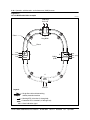
Because the connection is unidirectional the other direction (timeslot) can be
reused for another circuit. Unidirectional drop & continue on OPTera Metro
3500 can be used to provide applications such as; video broadcast,
Multi-Media conferencing and Distance Learning, for residential, business,
research and educational services.
OPTera Metro 3500 Multiservice Platform
NTRN10AN
Rel 12.1 Standard Iss 1 Apr 2004
Operation, administration, and maintenance (OAM) features 2-5
At the GE unidirectional add node, local client failures are propagated to the
far end using Client Signal Fail (CSF) client management frames. Refer to
Table 2-11 on page 2-78 for list of ingress LAN alarms. If subrate GE WAN
bandwidth is provisioned, enabling PAUSE flow control maybe required if the
connected equipment can not properly send the GE traffic to match the
provisioned WAN bandwidth.
Engineering rules
• Unidirectional Gigabit Ethernet traffic is supported on Linear and UPSR
rings.
• Gigabit Ethernet Drop and Continue traffic is supported for UPSR rings
only.
• A valid Gigabit Ethernet signal must be connected to the receiver interface
of the 2xGigE/FC-P2P at each drop node, otherwise GE idles will be
transmitted.
Note: An external optical splitter can be used to loop back the GE signal
from the Tx port to the Rx port of 2xGigE/FC-P2P, if the connected
equipment can not provide a valid GE signal.
•
A "Link down" alarm will be raised if you re-provision a bidirectional
connection to unidirectional. To prevent this alarm from being raised the
following steps must be performed:
— Delete all cross-connections to the WAN port
— Delete the Ethernet facility (DLT-ETH)
— Add the Ethernet facility (ENT-ETH)
— Re-enter the unidirectional cross-connection(s)
Note: Refer to Bandwidth Management, 323-1059-320, Equipment and
Facility Provisioning, 323-1059-350 and Alarm and Trouble Clearing,
323-1059-543.
•
Auto-negotiation (AN) can be enabled, however both the receive (Rx) and
transmit (Tx) fibers must connect to the same partner otherwise
auto-negotiation will not complete properly.
It is recommended to disable auto-negotiation (AN) and Pause transmit
(PAUSETX) frames at the drop nodes in this configuration.
•
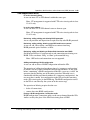
Alarm provisioning
Alarm provisioning allows you to disable or enable notification of an alarmed
condition for any SONET alarm point on a network element. You can enable
or disable alarm notification for one alarm or for a group of alarms with no
effect on the alarm function. Disable an alarm to prevent that alarm from being
reported to the user in any way (including alarm reports, TBOS, LEDs, or
Planning and Ordering Guide—Part 1 of 2 NTRN10AN
Rel 12.1 Standard Iss 1 Apr 2004
2-6 Operation, administration, and maintenance (OAM) features
audible and visible office alarm outputs). The network element, whether the
alarm point is disabled or enabled, records all alarms when the conditions that
cause an alarm occur.
Alarms are not lost after they are activated, whether enabled or disabled, and
can be retrieved when they are enabled. OPTera Metro 3500 stores a maximum
of 3000 active alarms, including both enabled and disabled alarms. The Active
Alarms window of Site Manager does not identify active disabled alarms. You
can retrieve a list of all disabled alarms from the Alarm Provisioning window,
by clicking the Alarms on Disabled Points tab.
Alarm profiles allow you to enable or disable defined groups of alarm points.
These groups are defined as Alarm classes. Alarm points are grouped by
facility type or equipment.
Each group of alarm points has two profiles defined by the system: All Alarms
ON and All Alarms OFF. At start-up, every group of alarm points has a default
profile of All Alarms ON, which becomes the active profile. You can create up
to three profiles for any group of alarm points. Each profile has a distinct name
and contains status information for each alarm or event that applies to that
profile. Profile names can contain an ASCII string of up to 20 characters that
cannot include quotation marks (“) or backslashes (\).
You can create, edit, and delete profiles. You can change all profiles, except the
two profiles defined by the system. However, you cannot delete or edit a profile
that is set as the default profile, or edit or delete the active profile if it is in use.
A new profile can be added to take care of additional requirements.
Alarm flow control
When a major fault occurs within a network, significant numbers of alarms are
raised on each shelf processor over a sustained period of time. The alarm flow
control (AFC) feature avoids situations in which Site Manager sessions log out
automatically due to TL1 request timeouts.
If the alarm rate is four alarms / second or greater, in a given ten minute period,
then this condition is considered excessive alarming and the ‘Alarm and Event
Throttling Active’ alarm is generated to warn users that further alarms will not
be reported.
When the system initiates alarm flow control, applications can continue to
generate alarms. The AFC feature only disables the reporting of alarms to the
screen or to file. User-initiated retrievals will continue to display all the alarms.
When the number of alarms being generated falls below the provisioned
threshold, the ‘Alarm and Event Throttling Active’ alarm is cleared and alarm
reporting resumes.
OPTera Metro 3500 Multiservice Platform
NTRN10AN
Rel 12.1 Standard Iss 1 Apr 2004
Operation, administration, and maintenance (OAM) features 2-7
Environmental alarms
Both the OPTera Metro 3500 and DS1 service module (DSM) support
environmental alarms. Each OPTera Metro 3500 shelf and DS1 service module
have 16 pairs of contacts that detect environmental alarms. The contacts are on
the environmental alarms connector of the left OAM (LOAM) and on the DSM
connected to the OAM power module. Set up environmental alarms during
provisioning.
The cooling fans on the OPTera Metro 3500 are detectable through pins
available from the backplane to the shelf processor. They are not connected to
an environmental alarm input for monitoring.
Alarm messages broadcast to all active user sessions.
External controls
The OPTera Metro 3500 network elements and DSM support external
controls. The external controls allow you to operate or release up to four relays
from any part of the network element or DSM. Connect the relays to external
equipment and program each relay with a control type attribute.
ACO switch — clearing audible alarms and performing lamp tests
The OPTera Metro 3500 network element and the DSM have an alarm cut-off
(ACO) button. The ACO button for the network element is on the left interface
(LIF) and the ACO button for the DSM is located on the fan faceplate of the
DSM. The alarm subsystem turns off the audible office alarm relay(s) when
you press the ACO button once.
Note: The ACO button on the network element also cuts off alarms and
performs lamp tests on connected DSMs.
The DSM has its own alarm cut-off button (ACO) because the DSM, although
connected to the shelf, can be located in another area that is far from the shelf.
You can turn off the audible alarms on both the network element and the DSM
from the Site Manager interface.
You can perform a lamp test on the network element or DSM by pressing the
ACO button twice.
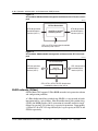
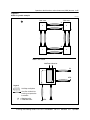
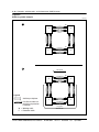
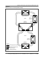
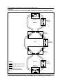
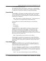
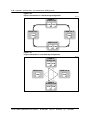
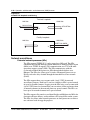
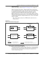
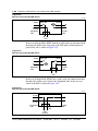
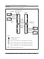
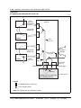
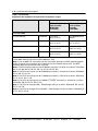
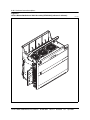
Bandwidth management
OPTera Metro 3500 supports a built-in, fully non-blocking switching matrix.
OPTera Metro 3500 is capable of routing up to 192 STS-1 signals, 5376 VT1.5
channels when equipped with VTX-48 or VTX-48e modules. See Figure 2-2
on page 2-10. With the introduction of new STS-192 circuit pack the OPTera
Metro 3500 is now capable of routing 768 STS-1 signals. See Figure 2-3 on
page 2-10. This eliminates the need for adjunct cross-connect facilities in most
applications.
Planning and Ordering Guide—Part 1 of 2 NTRN10AN
Rel 12.1 Standard Iss 1 Apr 2004
2-8 Operation, administration, and maintenance (OAM) features
OPTera Metro 3500 supports bandwidth management capabilities that include
time slot assignment (TSA), time slot interchange (TSI), hairpinning,
broadcast, drop-and-continue, path protection, unidirectional services,
connection editing, and in-service rollover. This bandwidth management
capability is available at VT1.5, STS-1, STS-3c, STS-12c, STS-24c and
STS-48c levels.
Features such as hairpinning between tributaries permit a single OPTera Metro
3500 shelf to be used instead of multiple colocated network elements.
Tributary, DWDM, BLSR, UPSR, and 1+1 linear point-to-point
• up to 48 STS-1s and 1344 VT1.5s (with VTX-series circuit pack)
• up to 192 STS-1s (with STX-192 circuit pack)
• slots 3 through 10 can each access up to 2.48 Gbit/s (with STX-192 circuit
pack)
• slots 3 through 10 can each access up to 622 Mbit/s (with VTX-series
circuit pack)
• optical slots 11 and 12 access up to10 Gbit/s (with STX-192 circuit pack)
• optical slots 11 and 12 access up to 622 Mbit/s2.48 Gbit/s (with
VTX-series circuit pack)
• the OPTera Metro 3500 shelf supports electrical and optical services and
interfaces from DS1, DS3s, EC-1, OC-48, OC-12, OC-3, 10/100BT, GE
and Fibre Channel. See Table 3-7 on page 3-52 for a complete list of
supported interfaces.
Note: In a configuration of 12 protected DSM shelves connected to a
single OPTera Metro 3500 shelf, up to 1008 DS1s are supported.
•
full VT/STS management is supported
Note: VT management is supported with VTX-48 or VTX-48e circuit
packs in slots 13 & 14 only.
•
each OPTera Metro 3500 shelf with two OC-48 or OC-192 DWDM optical
interface circuit packs can support one wavelength per circuit pack
each OPTera Metro 3500 shelf supports up to twelve protected DS1 service
module shelves or twelve unprotected DS1 service module shelves. Each
DS1 service module shelf supports 84 protected or unprotected DS1
facilities
For a complete list of electrical and optical interfaces supported by
VTX-48, VTX-48e and STX-192 circuit packs equipped OPTera Metro
3500 shelf, refer to Table 3-7 on page 3-52.
•
•
OPTera Metro 3500 Multiservice Platform
NTRN10AN
Rel 12.1 Standard Iss 1 Apr 2004
Operation, administration, and maintenance (OAM) features 2-9
BLSR
•
•
•
•
•
•
supports BLSR protocol on OC-192 circuit packs equipped with STX-192
circuit packs in slots 13 and 14.
supports BLSR protocol on OC-48 circuit packs equipped with
VTX-series circuit packs in slots 13 and 14.
— BLSR is not supported on OC-48 STS circuit packs equipped in slots
11 and 12.
VT1.5, STS-1, STS-3c, and STS-12c, connections supported on the OC-48
BLSR ring equipped with VTX-series circuit pack.
STS-1, STS-3c, STS-12c, STS-24c and STS-48c connections supported on
the OC-192 BLSR ring equipped with STX-192 circuit pack.
supports In service Channel Rollover and In service Route Rollover of
VT1.5, STS-1, STS-3c, STS-12c and STS-24c.
Note 1: VT1.5connections require VTX-series circuit pack.
Note 2: STS-24c connections are supported on 2xGigE/FC-P2P, OC-48
STS and OC-192 circuit packs.
supports OPE connections (RPR rings) at STS-1, STS-3c and STS-12c
over OC-48 or OC-192 BLSR.
Connection editing
Connection editing for the optical interface allows the user to change traffic
configurations through single or multiple connection type editing, while
maintaining live traffic. A forced switch or lockout may be required before the
edit to ensure that traffic is maintained.
In-service traffic rollover
In-service traffic rollover allows you to migrate live traffic within the transport
network. You can migrate any cross-connect end point to any other end point
capable of servicing the cross-connect rate, independent of the protection
scheme at the end point.
This operation is also supported to provide reconfigurations, such as merging
two UPSRs. This can be done on path-switched connections (1WAYPR and
2WAYPR) to move traffic from one cross-connect termination to a new
termination without disrupting service.
In service Channel Rollover in BLSR networks is the act of moving VT or STS
channels across time slots within a span. In service Route Rollover in BLSR
networks is the act of moving VT or STS channels from the short path to the
long path.
Note: In-service traffic rollover is not supported over RPR.
Planning and Ordering Guide—Part 1 of 2 NTRN10AN
Rel 12.1 Standard Iss 1 Apr 2004
2-10 Operation, administration, and maintenance (OAM) features
Figure 2-2
OPTera Metro 3500 bandwidth management architecture with VTX-series circuit
pack
EX0810t
OPTera Metro 3500
STS-48 equivalent
bandwidth optical
interface (slot 11)
192 STS or 5376 VT
Switching matrix
STS-48 equivalent
bandwidth optical
interface (slot 12)
STS-3 or STS-12 equivalent bandwidth
for tributary slots 3 to 10
Figure 2-3
OPTera Metro 3500 bandwidth management architecture with STX-192 circuit
pack
EX1491p
OPTera Metro 3500
STS-192 equivalent
bandwidth optical
interface (slot 11)
768 STS
Switching Matrix
STS-192 equivalent
bandwidth optical
interface (slot 12)
STS-1, STS-3, STS-12 or STS-48 equivalent
bandwidth for tributary slots 3 to 10
BLSR networks (2-fiber)
OPTera Metro 3500 supports 2-Fiber BLSR networks in its protection scheme
and configuration portfolios.
A 2-Fiber bidirectional line-switched ring (BLSR) is a ring network of nodes
interconnected by a pair of fibers. Like the unidirectional path-switched ring
(UPSR), the BLSR provides 100% restoration of restorable traffic for single
failures by reserving 50% of the ring’s capacity for protection. Consequently,
a 2-Fiber OC-48 or OC-192 ring effectively has a span capacity of STS-24 and
STS-96 respectively.
OPTera Metro 3500 Multiservice Platform
NTRN10AN
Rel 12.1 Standard Iss 1 Apr 2004
Operation, administration, and maintenance (OAM) features 2-11
A BLSR offers a network-level protection capability, and differs from a UPSR
in that the nodes in a BLSR are aware of the larger configuration. In a BLSR,
switching nodes communicate to each other through K-bytes. A UPSR node
has no network knowledge and does not rely upon any APS communication
with other nodes.
Protection
Protection in a BLSR is provided by using a time slot select function. The
network elements adjacent to the protected span bridges the working time slots
in the failed direction to the preassigned protection time slots in the direction
away from the failure. The network element where the signal is dropped from
the ring receives (selects) from the protection time slots on the side away from
the failure.
A BLSR bridge request can be initiated either by an operator or autonomously.
Note: All user-initiated protection switching commands are signaled on
the APS channels (K1 and K2 bytes).
User-initiated BLSR switching commands
•
•
•
Forced switch
— This command performs the ring switch from the working to the
protection channels for the span between the node at which the
command is initiated and the adjacent node to which the command is
destined. This switch occurs regardless of the state of the protection
channels, unless the protection channels are satisfying a higher priority
request.
Manual switch
— This command performs the ring switch from the working to the
protection channels for the span between the node at which the
command was initiated and the node to which the command was
destined. This occurs if the protection channels to be used are operating
at a BER better than the signal degrade threshold and are not satisfying
an equal or higher priority request (including failure of the protection
channels).
Lockout of working/protection
— These command performs a lockout (working or protection) which
prevents the working line from switching to the protection line. When
you perform a lockout, you prevent traffic from switching to the
protection line. If traffic is on the protection line, it returns to the
working line regardless of the condition of the working line. After you
initiate a lockout request, the lockout request remains active until you
release it. The lockout command has the highest priority.
Planning and Ordering Guide—Part 1 of 2 NTRN10AN
Rel 12.1 Standard Iss 1 Apr 2004
2-12 Operation, administration, and maintenance (OAM) features
Lockout of working: prevents a protection switch of the working line
to the protection line.
Lockout of protection: prevents any of the channels from switching to
the protection line.
Automatically initiated BLSR switching requests
•
Signal fail (SF)
— SF is a hard failure caused by a Loss of Signal, Loss of Frame, a line
BER exceeding a preselected threshold, a line AIS, or some other
protectable hard failure. All channels with the SF condition are
protected using the ring switch.
• Signal degrade (SD)
— SD is a soft failure caused by a BER exceeding a preselected threshold.
It can be used to detect gradual degradation of service to perform
preventive maintenance. All degraded lines are protected using the ring
switch.
• Reverse request (RR)
— RR is transmitted to the tail-end network element on the Short Path as
an acknowledgement for receiving the Short Path ring bridge request.
• Wait to restore (WTR)
— WTR is issued when working channels meet the restoral threshold after
an SD or SF condition. This request is used to maintain the current state
during the WTR period unless it is pre-empted by a higher priority
request.
When a failure occurs in the ring, the ring switches are performed by the nodes
immediately adjacent to the failed segment. It should be noted that a failed
segment may be a single span or many spans with multiple nodes.
For a 2-Fiber BLSR operating at an OC-48 rate, time slot numbers 1 through
24 at the multiplex input are reserved for working channels. Time slot number
‘X’ of the first fiber is protected using time slot number ‘X + 24’ of the second
fiber in the opposite direction, where X is an integer between 1 and 24.
Similarly, for a 2-Fiber BLSR operating at an OC-192 rate, time slot numbers
1 through 96 at the multiplex input are reserved for working channels. Time
slot number ‘X’ of the first fiber is protected using time slot number ‘X + 96’
of the second fiber in the opposite direction, where X is an integer between 1
and 96.
’Infinite wait-to-restore’ parameter
OPTera Metro 3500 allows users to provision an infinite wait-to-restore period
in BLSR-protected optical interfaces. This effectively allows users to
provision BLSRs to autonomously switch non-revertively.
OPTera Metro 3500 Multiservice Platform
NTRN10AN
Rel 12.1 Standard Iss 1 Apr 2004
Operation, administration, and maintenance (OAM) features 2-13
BLSR Line Protection Oscillation Control
OPTera Metro Release 12.0 introduced a line protection oscillation control
mechanism for BLSR systems. If 3 signal failures (SF) are detected on a line
within 12 seconds of each other the line protection oscillation control
mechanism is activated and protection will be in a lockout condition for 12
seconds. The OPTera Metro 3500 will raise an “Auto Switch Complete Oscillation” alarm. The lockout condition is released only after 12 seconds
have elapsed without a signal fail (SF) transition.
This feature is not provisionable and is always on.
BLSR single span fiber cut scenario
A fiber cut - and any other cause of signal degradation or signal failure on a
span - causes a BLSR autonomous switch. A fiber degradation scenario is
described in the following example. See Figure 2-4 on page 2-17 to Figure
2-11 on page 2-24 to see the following order of events after a signal
degradation between Node 3 and Node 4 occurs.
Note: The following steps correspond to the step numbers in the graphics.
Planning and Ordering Guide—Part 1 of 2 NTRN10AN
Rel 12.1 Standard Iss 1 Apr 2004
2-14 Operation, administration, and maintenance (OAM) features
BLSR single span Fiber cut example
Step
Action
1
The BLSR ring is clean. Tributaries are added/dropped at Nodes 1 and 4.
2
The signal from Node 4 to Node 3 is degraded.
3
4
•
Node 3 detects failure.
•
Node 4 is unaware there is a problem.
Node 3 sends K-byte messages to Node 4 on the Short and Long paths. The
K-byte messages are 2 bytes in the SONET overhead that contain:
•
source node (Node 3)
•
destination node (Node 4)
•
type of switch request (Signal Degrade)
•
path direction (Long, Short)
•
node status (Short Path sends ‘RDI’; Long Path sends ‘Idle’)
Node 4 receives the message on the Short Path.
Node 4 sends a Signal Degrade switch request back to Node 3 on the Long
Path.
•
source node (Node 4)
•
destination node (Node 3)
•
type of switch request (Signal Degrade)
•
path direction (Long)
•
node status (’Idle’)
Node 4 sends a Reverse Request message back to Node 3 on the Short
Path, acknowledging the receipt of the Short Path bridge request (the Signal
Degrade, RDI message).
5
•
source node (Node 4)
•
destination node (Node 3)
•
type of switch request (Reverse Request)
•
path direction (Short)
•
node status (’Idle’)
Nodes 1 and 2 enter into a ‘Passthrough’ state after receiving the message
from Node 3 to Node 4 on the Long Path.
Note: Nodes 1 and 2 check the ‘Destination Node’ attribute of the message
to see if it is addressed to them. They send the message unchanged to the
next node in the ring in the same direction.
—continued—
OPTera Metro 3500 Multiservice Platform
NTRN10AN
Rel 12.1 Standard Iss 1 Apr 2004
Operation, administration, and maintenance (OAM) features 2-15
BLSR single span Fiber cut example
Step
Action
6
Node 4 receives the message on the long path, and enters into a ‘Bridged’
state. Node 4 bridges traffic from the incoming working channels to the
opposite direction, outgoing protection channels. Node 4 acknowledges
receipt of the message by sending a ‘Bridged’ message back to Node 3 on
the Long Path.
•
source node (Node 4)
•
destination node (Node 3)
•
type of switch request (Signal Degrade)
•
path direction (Long)
•
node status (’Bridged’)
Note: Nodes 1 and 2 remain in the ‘Passthrough’ state.
7
8
Node 3 receives the ‘Signal Degrade’ request from Node 4, and enters into a
‘Bridged’ state. Node 3 bridges traffic from the working to the protection
channels and acknowledges receipt of the message by sending a ‘Bridged’
message back to Node 4 on the Long Path.
•
source node (Node 3)
•
destination node (Node 4)
•
type of switch request (Signal Degrade)
•
path direction (Long)
•
node status (’Bridged’)
Node 4 receives the ‘Bridged’ status indication from Node 3. Node 4 enters
into the ‘Bridged and Switched’ state. Traffic received on the protection
channels are then routed as if they were received from the failed working link.
Node 4 then sends a message to Node 3 indicating that it has entered into
the ‘Bridged and Switched’ state.
•
source node (Node 4)
•
destination node (Node 3)
•
type of switch request (Signal Degrade)
•
path direction (Long)
•
node status (’Bridged and Switched’)
Note: Depending on the cross-connects provisioned, Node 4 will then either
drop traffic at the add/drop multiplexer or route traffic back out onto the
working channels of the ring.
—continued—
Planning and Ordering Guide—Part 1 of 2 NTRN10AN
Rel 12.1 Standard Iss 1 Apr 2004
2-16 Operation, administration, and maintenance (OAM) features
BLSR single span Fiber cut example
Step
Action
9
Node 3 receives the ‘Bridged’ status indication from Node 4. Node 3 enters
into the ‘Bridged and Switched’ state. Traffic received on the protection
channels are then routed as if they were received from the failed working link.
Node 4 then sends a message to Node 3 indicating that it has entered into
the ‘Bridged and Switched’ state.
•
source node (Node 3)
•
destination node (Node 4)
•
type of switch request (Signal Degrade)
•
path direction (Long)
•
node status (’Bridged and Switched’)
Note: Depending on the cross-connects provisioned, Node 3 will then either
drop traffic at the add/drop multiplexer or route traffic back out onto the
working channels of the ring.
10
Switch is complete.
—end—
OPTera Metro 3500 Multiservice Platform
NTRN10AN
Rel 12.1 Standard Iss 1 Apr 2004
Operation, administration, and maintenance (OAM) features 2-17
Figure 2-4
BLSR ring switch example
EX1230p
'Idle' state
1
'Idle' state
W
4
W
P
P
W
P
P
W
W
1
3
W
P
P
W
P
P
W
2
W
'Idle' state
'Idle' state
Node 1 and 4 detail
Add/Drop tributaries
W
P
P
UEQ
W
W
Legend
P
Add/drop multiplexer
P
W
One fiber divided into
working and protection
bandwidth
W = Working traffic
P = Protection traffic
UEQ
P
W
Planning and Ordering Guide—Part 1 of 2 NTRN10AN
Rel 12.1 Standard Iss 1 Apr 2004
2-18 Operation, administration, and maintenance (OAM) features
Figure 2-5
BLSR ring switch example
EX1231p
2
W
4
P
P
3
W
W
W
P
P
P
W
P
W
P
W
W
1
P
P
2
W
3
Short path
SD/3/4/S/RDI
W
4
P
P
3
W
W
Legend
W
P
P
W
W
Add/drop multiplexer
P
W
1
One fiber divided into
working and protection
bandwidth
P
P
2
W
Long path
W = Working traffic
P = Protection traffic
OPTera Metro 3500 Multiservice Platform
P
SD/3/4/L/idle
NTRN10AN
Rel 12.1 Standard Iss 1 Apr 2004
Operation, administration, and maintenance (OAM) features 2-19
Figure 2-6
BLSR ring switch example
EX1241p
4
W
4
P
P
3
W
W
Short path
P
W
P
RR/4/3/S/Idle
P
P
W
W
W
1
P
P
2
W
Long path
SD/4/3/L/idle
Node 1 and 2 state change detail
W
5
PP
W
Idle
state
W
UEQ
P
P
W
W
Pass-through
state
Legend
PP
W
Add/drop multiplexer
P
W
One fiber divided into
working and protection
bandwidth
W = Working traffic
P = Protection traffic
W
P
P
W
Planning and Ordering Guide—Part 1 of 2 NTRN10AN
Rel 12.1 Standard Iss 1 Apr 2004
2-20 Operation, administration, and maintenance (OAM) features
Figure 2-7
BLSR ring switch example
EX1232p
'Bridged' state
6
'Idle' state
W
4
P
P
3
W
W
W
P
P
P
P
W
W
W
1
P
P
2
W
'Pass-through'
state
'Pass-through'
state
Long path
SD/4/3/L/bridged
Node 3 and 4 state change detail
W
Idle
state
P
P
UEQ
W
W
P
P
W
Bridged
state
W
Legend
P
P
Add/drop multiplexer
P
W
W
One fiber divided into
working and protection
bandwidth
W
W = Working traffic
P = Protection traffic
OPTera Metro 3500 Multiservice Platform
P
P
NTRN10AN
W
Rel 12.1 Standard Iss 1 Apr 2004
Operation, administration, and maintenance (OAM) features 2-21
Figure 2-8
BLSR ring switch example
EX1242p
'Bridged' state
'Idle' state
W
4
P
P
3
W
W
P
W
P
P
W
P
W
W
1
P
P
2
W
'Pass-through'
state
Long path
'Pass-through'
state
SD/4/3/L/bridged
Legend
Add/drop multiplexer
P
W
One fiber divided into
working and protection
bandwidth
W = Working traffic
P = Protection traffic
Planning and Ordering Guide—Part 1 of 2 NTRN10AN
Rel 12.1 Standard Iss 1 Apr 2004
2-22 Operation, administration, and maintenance (OAM) features
Figure 2-9
BLSR ring switch example
EX1233p
7
'Bridged' state
'Bridged' state
W
4
3
P
P
W
W
P
W
P
P
W
P
W
W
1
P
P
2
W
'Pass-through'
state
Long path
'Pass-through'
state
SD/4/3/L/bridged
8
'Bridged and
Switched' state
'Bridged' state
W
4
P
3
P
W
W
W
P
P
P
P
W
W
W
Legend
1
Add/drop multiplexer
P
W
P
P
2
W
One fiber divided into
working and protection
bandwidth
'Pass-through'
state
'Pass-through'
state
W = Working traffic
P = Protection traffic
OPTera Metro 3500 Multiservice Platform
NTRN10AN
Rel 12.1 Standard Iss 1 Apr 2004
Operation, administration, and maintenance (OAM) features 2-23
Figure 2-10
BLSR ring switch example
EX1243p
Node 3 and 4 state change detail
W
Bridged
state
P
P
W
W
P
P
W
Bridged and
Switched
state
W
P
P
W
W
P
Totally
decoupled
P
9
W
'Bridged and
Switched' state
'Bridged and
Switched' state
W
4
3
P
P
W
W
W
P
P
Legend
Add/drop multiplexer
P
W
One fiber divided into
working and protection
bandwidth
W = Working traffic
P = Protection traffic
P
P
W
W
W
1
P
P
2
W
'Pass-through'
state
Long path
'Pass-through'
state
SD/4/3/L/bridged and switched
Planning and Ordering Guide—Part 1 of 2 NTRN10AN
Rel 12.1 Standard Iss 1 Apr 2004
2-24 Operation, administration, and maintenance (OAM) features
Figure 2-11
BLSR ring switch example
EX1234p
10
Switching
nodes
'Bridged and
Switched' state
'Bridged and
Switched' state
W
4
P
3
P
W
W
W
P
P
Pass-through
nodes
P
P
W
W
W
1
P
P
2
W
'Pass-through'
state
Long path
'Pass-through'
state
SD/4/3/L/bridged and switched
Legend
Add/drop multiplexer
P
W
One fiber divided into
working and protection
bandwidth
W = Working traffic
P = Protection traffic
OPTera Metro 3500 Multiservice Platform
NTRN10AN
Rel 12.1 Standard Iss 1 Apr 2004
Operation, administration, and maintenance (OAM) features 2-25
BLSR nodal / multi-span failure scenario (involves squelching)
In the instance in which one or more nodes becomes disconnected because of
multiple line failures and/or nodal failures, a BLSR network enters into a
bidirectional protected state of operation. The protection operation is much the
same as for the loss of a span, except that add-drop traffic at the affected node
is lost.
Figure 2-12 on page 2-27 and Figure 2-13 on page 2-28 illustrate failure in
Node C for OC-48 and OC-192 BLSR respectively. Traffic normally intended
to pass through Node C is looped back to the appropriate protection timeslots
at Nodes B and D. The traffic is then routed to the intended destinations as
described for link failures. The nodes performing the protection switch are
termed switch nodes.
During protection switching, traffic that normally exits the ring at the lost node
has the potential to be misconnected to another path termination. To ensure
that this does not happen, the nodes adjacent to the failed node (in the example,
Nodes B and D) squelch the appropriate working and protection paths by
inserting into them a path AIS (alarm indication signal) before completing the
protection switch. These paths continue to be given path AIS until the ring
returns to normal operation.
The squelching is performed by the switch nodes on the basis of a squelch map
that is automatically derived from the node map and STS-1 cross-connection
map when these maps are provisioned. The squelch map has an entry for each
STS-1 cross-connection provisioned at the ADM node. Each entry contains the
APS IDs of the nodes providing the service access point (SAP) and end node
for that STS-1.
If a node loses communication with the SAP or end node for a particular STS-1
(for example, because of a failure of the SAP or end node or because of a ring
segmentation isolating the SAP or end node), it can then squelch the path.
Pass-through connections at the failed node are not squelched, as these can be
successfully rerouted over the protection path. Figure 2-14 on page 2-29 shows
an example of a four-node ring with four STS-1 paths (a, b, c, and d). The
arrows indicate the direction of each path, from the originating node (SAP) to
the end node.
Table 2-3 on page 2-26 specifies the squelch map for Node D.
Planning and Ordering Guide—Part 1 of 2 NTRN10AN
Rel 12.1 Standard Iss 1 Apr 2004
2-26 Operation, administration, and maintenance (OAM) features
Table 2-3
Node D squelch map (example)
Connection
SAP node ID
End node ID
b
A
B
c
D
A
d
C
D
If Node D fails, path c is squelched at Node A and path d is squelched at Node
C. Path b is not squelched, as the path is rerouted from Node A to Node B by
the protection switch. Path a is unaffected by the protection switch, as it does
not route through the failed node.
OPTera Metro 3500 Multiservice Platform
NTRN10AN
Rel 12.1 Standard Iss 1 Apr 2004
Operation, administration, and maintenance (OAM) features 2-27
Figure 2-12
OC-48 BLSR node failure example
F2140
(Add-drop)
A-D A-B
Fiber 1
A
Ring ADM
Fiber 2
D-A
B
D
D-C (AIS)
D-B
Bridge
(B-D)
B-A
B-C (AIS)
B-D
C
Node
failure
C-D C-B
Legend:
= Single fiber cable with 24 working
and 24 protection timeslots
= Working STS-1 timeslots (1 through 24)
= Protection STS-1 timeslots (25 through 48)
AIS = Alarm indication signal
Planning and Ordering Guide—Part 1 of 2 NTRN10AN
Rel 12.1 Standard Iss 1 Apr 2004
2-28 Operation, administration, and maintenance (OAM) features
Figure 2-13
OC-192 BLSR node failure example
EX1497p
(Add-drop)
A-D A-B
Fiber 1
A
Ring ADM
Fiber 2
D-A
B
D
D-C (AIS)
D-B
Bridge
(B-D)
B-A
B-C (AIS)
B-D
C
Node
failure
C-D C-B
Legend:
= Single fiber cable with 96 working
and 96 protection timeslots
= Working STS-1 timeslots (1 through 96)
= Protection STS-1 timeslots (97 through 192)
AIS = Alarm indication signal
OPTera Metro 3500 Multiservice Platform
NTRN10AN
Rel 12.1 Standard Iss 1 Apr 2004
Operation, administration, and maintenance (OAM) features 2-29
Figure 2-14
STS paths and squelch map for a four-node 2-Fiber BLSR ring
F2247
Node A
Node B
STS #3
(path a)
(path b)
(path c)
(path b)
STS #1
STS #2
STS #2
STS #3
Line
STS #2
(path c)
(path a)
STS #1
(path d)
(path d)
Node C
Node D
Line
BLSR configurations
The configuration of the BLSR ring is recorded in a BLSR configuration,
which is created on the NPx and then propagated to all the SPx circuit packs
in the BLSR ring.
BLSR configuration attributes
A BLSR configuration contains the following information:
• Ring name
• Optical interfaces involved in the ring (for each node in the ring)
• The associated automatic protection switching (APS) IDs of the involved
optical interfaces (for each node in the ring)
• The adjacent nodes’ APS IDs and TIDs (for each node in the ring)
Note 1: The allowable string characters are "0-9", "A-Z", and "-".
Note 2: The allowable range for an APS ID is between 0 and 15.
Planning and Ordering Guide—Part 1 of 2 NTRN10AN
Rel 12.1 Standard Iss 1 Apr 2004
2-30 Operation, administration, and maintenance (OAM) features
BLSR configuration distribution
The distribution process of a BLSR configuration from the NPx to the other
nodes in the BLSR is controlled by the combinations of results arising from the
following user-initiated actions:
• creating/deleting/editing a BLSR ring
• creating/deleting a BLSR configuration
• checking/loading/invoking/committing a BLSR configuration
• canceling a BLSR configuration (valid at any point before ‘commit’)
When a new BLSR configuration is provisioned, a ‘temporary’ BLSR
configuration is created. This BLSR configuration is activated when the
‘Invoke’ button is clicked in Site Manager. Any prior BLSR configuration is
deleted after the ‘Commit’ button is clicked in Site Manager.
BLSR configuration and connection audit
The BLSR configuration and connection audit feature is enabled by default.
Both audits are run by the system once every 1440 minutes (24 hours) by
default. This period is provisionable with a range of 15 minutes to 10080
minutes (7 days) in 15 minute increments.
The BLSR configuration and connection audit feature performs two tasks:
• The BLSR configuration audit function determines if the working BLSR
configuration on the NPx (master copy) is the same as the BLSR
configurations on the SPx circuit packs around the BLSR ring.
• The BLSR connection audit function determines if pass-through
connections in the BLSR have the proper End NE A and End NE Z
information provisioned.
BLSR configuration audit
If there is a discrepancy discovered in the configuration audit, the "BLSR
Configuration Audit Fail" alarm is raised on the SPx. At this time, the user is
able to force down the master copy of the BLSR configuration from the NPx
to the faulty SPx by going through the loading, invoking, and committing steps
on the NPx.
OPTera Metro 3500 Multiservice Platform
NTRN10AN
Rel 12.1 Standard Iss 1 Apr 2004
Operation, administration, and maintenance (OAM) features 2-31
BLSR connection audit
If there is a discrepancy discovered in the connection audit, the "BLSR
Connection Audit Failed" alarm is raised against the pass-through node with
the inconsistency.
BLSR connection audit behaviour is as follows:
• The BLSR connection audit feature resides on the NPx.
• The audit period is user-provisionable.
• If the audit cannot connect to a node’s SPx, the NPx will output the
autonomous message "BLSR Connection Audit could not connect to SP"
• The audit will determine the correct End NE A and End NE Z information
of a path by looking at the Add/Drop points of the existing path.
• When an audit is complete, the NPx will output the autonomous message
"BLSR Connection Audit completed".
• The "BLSR Connection Audit Failed" alarm is cleared upon the next
successful BLSR connection audit.
• The BLSR connection audit feature can only raise an alarm if the entire
path is provisioned. For partial paths (for example, during the provisioning
of a path), an alarm is not raised.
Traffic flow over OC-48 BLSR
All traffic types previously supported on the OPTera Metro 3500 shelf are
supported in Release 12.1.
OC-48 BLSR is supported on OPTera Metro 3500 shelves equipped with
VTX-series circuit packs in slots 13 and 14.
STS BLSR with VT assignment
In VT assigned BLSRs, users must provision STS connections at pass-through
nodes. This gives a number of distinct advantages to the user:
• There are fewer connections for the user to manage.
• There are fewer, therefore quicker, connection retrievals on pass-through
nodes.
Note: The number of fewer connections can be estimated to be:
16 nodes x 24 available STS/node x 1/2 used for passthrough x 28 VT/STS
= 5376 fewer possible connections.
•
The BLSR topology of OPTera Metro 3500 supports interoperability with
STS-based products like OPTera Connect HDX, OPTera Connect DX and
TransportNode OC-48 subtended BLSRs.
Planning and Ordering Guide—Part 1 of 2 NTRN10AN
Rel 12.1 Standard Iss 1 Apr 2004
2-32 Operation, administration, and maintenance (OAM) features
VT assigned end-to-end connections necessarily possess the following
characteristics:
• For any given end-to-end VT connection, add and drop nodes must be
provisioned with VT connections and pass-through nodes must be
provisioned with STS connections
• If one VT end-to-end connection within an STS is provisioned as VT
assigned, then all of the VTs within that STS must be VT assigned
• All VT assigned end-to-end connections within an STS channel must
terminate (add/drop) at the same node
• All of the VTs within an STS channel must terminate (add/drop) at the
same node
VT BLSR with full VT access
OPTera Metro 3500 supports full VT access (Full VT mode) in a BLSR. When
an end-to-end connection is provisioned as Full VT, all nodes along the length
of the connection (add, drop, and pass-through) are VT connections. In
addition, VTs in a given STS can be added and dropped to and from any where
in the network. This optimizes bandwidth efficiency and provisioning
flexibility.
Note: Full VT mode is only supported in OC-48 BLSR rings wherein all
the nodes are OPTera Metro 3500 network elements equipped with
VTX-series circuit packs.
Traffic flow over OC-192 BLSR
OC-192 BLSR is supported on OPTera Metro 3500 shelves equipped with
OC-192 circuit packs in slots 11 and 12 and with STX-192 circuit packs in
slots 13 and 14.
STS BLSR
The STX-192 circuit pack supports STS-managed traffic only,
The BLSR topology of OPTera Metro 3500 supports interoperability with
OPTera Connect DX at the OC-192 line rate.
OPTera Metro 3500 Multiservice Platform
NTRN10AN
Rel 12.1 Standard Iss 1 Apr 2004
Operation, administration, and maintenance (OAM) features 2-33
Figure 2-15
STS BLSR with VT assignment support with VTX-48 or VTX-48e circuit pack (example)
EX1244p
DS1
OC-48
OC-48
4
11 12
To
2WAY From
DS1
OC-48
slot :4 slot :11
port :1 STS-1 :1
VTG :1
VT1.5 :1
Network Element D
(protection pass-through)
(see Note)
OC-48
OC-48
OC-48
OC-48
Network Element A
(DS1 add/drop)
Network Element B
(working pass-through)
DS1
OC-48
OC-48
11 12
6
11 12
Network Element C
(DS1 add/drop)
2WAY
2WAY From
To
OC-48 OC-48
slot :12 slot :11
STS-1:1 STS-1 :1
11 12
From
OC-48
slot :12
STS-1 :1
VTG :1
VT1.5 :1
To
DS1
slot :6
port :7
Legend
= Fiber pair (duplex)
= Cross-connect
= Working channel
= Protection channel
Note: There is no need to provision a cross-connect for a protection
pass-through connection in a BLSR ring.
Planning and Ordering Guide—Part 1 of 2 NTRN10AN
Rel 12.1 Standard Iss 1 Apr 2004
2-34 Operation, administration, and maintenance (OAM) features
Provisioning rules
The following BLSR provisioning rules represent the sum of engineering rules
- as enforced by system software - plus provisioning recommendations.
CAUTION
Risk of traffic loss
Blocking of provisioning is performed only at a nodal level. Channel reserving /
blocking does not span more than one section. After using the provisioning rules
to determine which channels are reserved / blocked on the east and west fiber
sections adjacent to an add / drop node, users should ensure they respect these
‘reserved’ and ‘blocked’ time slot assignments in all downstream fiber sections
until the far-end add / drop node. Provisioning over these time slot assignments
downstream may result in dropped traffic if a protection switch occurs.
Table 2-4
OC-48/OC-192 BLSR provisioning rules
Rule # Description
1
Only the working channels may be provisioned as non-RPR connections
Note 1: For OC-48 BLSR the working channels are any of the STS-1 #1 through #24.
Note 2: For OC-48 BLSR, STS-1 #25 through #48 are reserved for non-RPR protection and may not be
provisioned as unprotected channels for non-RPR traffic.
Note 3: For OC-192 BLSR the working channels are any of the STS-1 #1 through #96.
Note 4: For OC-192 BLSR, STS-1 #97 through #192 are reserved for non-RPR protection and may not
be provisioned as unprotected channels for non-RPR traffic
2
RPR traffic may be provisioned on STS-1 #1 through #48 for OC-48 BLSR or STS-1 #1 through
#192 for OC-192 BLSR
3
Mixed scenarios (both RPR and non-RPR traffic sharing the same BLSR fiber span) may be
provisioned.
— Provisioning rules #1 and #2 apply in mixed scenarios for their respective traffic types.
— If a working channel is provisioned for non-RPR traffic, its protection channel is committed to being
protection and may not be used for RPR traffic.
— If a protection channel is provisioned for RPR traffic, its working channel may not be provisioned as
a non-RPR connection.
— If an East working channel (any of STS-1 #1 through #24 for OC-48 BLSR or STS-1 #1 through #96
for OC-192 BLSR) is provisioned for RPR traffic, the West working channel with the same time slot
assignment is reserved for RPR provisioning.
Note: The same is true if the West working channel is provisioned as an RPR connection before the East
working channel.
4
RPR connections on the East side of a ring must have the same signal rate as the RPR
connection (on the same time slot assignment) on the West side of the same ring.
OPTera Metro 3500 Multiservice Platform
NTRN10AN
Rel 12.1 Standard Iss 1 Apr 2004
Operation, administration, and maintenance (OAM) features 2-35
Table 2-4 (continued)
OC-48/OC-192 BLSR provisioning rules
5
In the following types of RPRs, it is recommended that only the working channels may be
provisioned for RPR connections:
— RPRs with subtending UPSRs
— Virtual RPRs
6
VT-assigned connections within the same STS-1 channel must have the same Aend/Zends
(Add/Drop points).
Note: VT-assigned connections are only supported on shelves equipped with VTX-series circuit packs.
7
VT-assigned connections must not be provisioned in the same STS as Full VT connections.
Note: VT-assigned connections are only supported on shelves equipped with VTX-series circuit packs.
Planning and Ordering Guide—Part 1 of 2 NTRN10AN
Rel 12.1 Standard Iss 1 Apr 2004
2-36 Operation, administration, and maintenance (OAM) features
Example of provisioning rules for OC-48 BLSR (RPR provisioned on working
channel)
In Figure 2-16 on page 2-36, a user provisions STS-1 #5 on the West optical
interface (OC-48 in slot 11) as an RPR connection. See Table 2-4 on page 2-34
for provisioning rules.
• STS-1 #29 on the East side is reserved for RPR provisioning because
non-RPR connections may not be provisioned in the designated protection
channels (any of STS-1 #25 through #48).
• STS-1 #29 on the East side cannot be a non-RPR protection channel
because the working channel on the West side has already been
provisioned as an RPR connection.
• STS-1 #5 on the East side is reserved for RPR provisioning because
STS-1 #5 on the West side has been provisioned as an RPR connection.
(See provisioning rule #3)
• STS-1 #29 on the West side is reserved for RPR provisioning because
non-RPR connections may not be provisioned in the designated protection
channels (any of STS-1 #25 through #48).
• STS-1 #29 on the West side cannot be a non-RPR protection channel
because the working channel on the East side is already reserved for RPR
provisioning. (See third bullet of this example, provisioning rule #3).
Figure 2-16
Example of BLSR provisioning rules OC-48 (RPR connection provisioned)
EX1293p
OC-48
in slot 11
OC-48
in slot 12
West optics
Protection
channels
(STS-1
#25-48)
Working
channels
(STS-1
#1-24)
East optics
STS-1
#25-48
STS-1 #29
STS-1 #29
STS-1 #5
STS-1 #5
STS-1
#1-24
Legend
= STS-1 provisioned as RPR
= STS-1 subsequently reserved for RPR provisioning
OPTera Metro 3500 Multiservice Platform
NTRN10AN
Rel 12.1 Standard Iss 1 Apr 2004
Operation, administration, and maintenance (OAM) features 2-37
Example of provisioning rules for OC-48 BLSR (non-RPR provisioned on
working channel)
In Figure 2-17 on page 2-37, a user provisions STS-1 #5 on the West optical
interface (OC-48 in slot 11) as an non-RPR connection. See Table 2-4 on page
2-34 for provisioning rules.
• STS-1 #29 on the East side is reserved as a non-RPR protection channel.
(See provisioning rule #1, provisioning rule #3)
• STS-1 #5 on the East side is reserved for non-RPR provisioning because
RPR provisioning rules over BLSR conflict with STS-1 #5 on the West
side and STS-1 #29 on the East side. (See provisioning rule #3)
• STS-1 #29 on the West side is reserved as a non-RPR protection channel
because STS-1 #5 on the East side is non-RPR. (See last bullet of this
example, provisioning rule #3).
Figure 2-17
Example of BLSR provisioning rules OC-48 BLSR (non-RPR connection
provisioned)
EX1294p
OC-48
in slot 11
West optics
Protection
channels
(STS-1
#25-48)
Working
channels
(STS-1
#1-24)
OC-48
in slot 12
East optics
STS-1
#25-48
STS-1 #29
STS-1 #5
STS-1 #29
STS-1 #5
STS-1
#1-24
Legend
= STS-1 provisioned as non-RPR
= STS-1 subsequently reserved as a non-RPR protection channel
= STS-1 subsequently restricted from RPR provisioning
Planning and Ordering Guide—Part 1 of 2 NTRN10AN
Rel 12.1 Standard Iss 1 Apr 2004
2-38 Operation, administration, and maintenance (OAM) features
Example of provisioning rules for OC-192 BLSR (RPR provisioned on working
channel)
In Figure 2-18 on page 2-38, a user provisions STS-1 #5 on the West optical
interface (OC-192 in slot 11) as an RPR connection. See Table 2-4 on page
2-34 for provisioning rules.
• STS-1 #101 on the East side is reserved for RPR provisioning because
non-RPR connections may not be provisioned in the designated protection
channels (any of STS-1 #97 through #192).
• STS-1 #101 on the East side cannot be a non-RPR protection channel
because the working channel on the West side has already been
provisioned as an RPR connection.
• STS-1 #5 on the East side is reserved for RPR provisioning because
STS-1 #5 on the West side has been provisioned as an RPR connection.
(See provisioning rule #3)
• STS-1 #101 on the West side is reserved for RPR provisioning because
non-RPR connections may not be provisioned in the designated protection
channels (any of STS-1 #97 through #192).
• STS-1 #101 on the West side cannot be a non-RPR protection channel
because the working channel on the East side is already reserved for RPR
provisioning. (See third bullet of this example, provisioning rule #3).
Figure 2-18
Example of BLSR provisioning rules OC-192 (RPR connection provisioned)
EX1498p
OC-192
in slot 11
OC-192
in slot 12
West optics
Protection
channels
(STS-1
#97-192)
Working
channels
(STS-1
#1-96)
East optics
STS-1
#97-192
STS-1 #101
STS-1 #101
STS-1 #5
STS-1 #5
STS-1
#1-96
Legend
= STS-1 provisioned as RPR
= STS-1 subsequently reserved for RPR provisioning
OPTera Metro 3500 Multiservice Platform
NTRN10AN
Rel 12.1 Standard Iss 1 Apr 2004
Operation, administration, and maintenance (OAM) features 2-39
Example of provisioning rules for OC-192 BLSR (non-RPR provisioned on
working channel)
In Figure 2-19 on page 2-39, a user provisions STS-1 #5 on the West optical
interface (OC-192 in slot 11) as an non-RPR connection. See Table 2-4 on
page 2-34 for provisioning rules.
• STS-1 #101 on the East side is reserved as a non-RPR protection channel.
(See provisioning rule #1, provisioning rule #3)
• STS-1 #5 on the East side is reserved for non-RPR provisioning because
RPR provisioning rules over BLSR conflict with STS-1 #5 on the West
side and STS-1 #99 on the East side. (See provisioning rule #3)
• STS-1 #101 on the West side is reserved as a non-RPR protection channel
because STS-1 #5 on the East side is non-RPR. (See last bullet of this
example, provisioning rule #3).
Figure 2-19
Example of BLSR provisioning rules OC-192 BLSR (non-RPR connection
provisioned)
EX1499p
OC-192
in slot 11
West optics
Protection
channels
(STS-1
#97-192)
Working
channels
(STS-1
#1-96)
OC-192
in slot 12
East optics
STS-1
#97-192
STS-1 #101
STS-1 #5
STS-1 #101
STS-1 #5
STS-1
#1-96
Legend
= STS-1 provisioned as non-RPR
= STS-1 subsequently reserved as a non-RPR protection channel
= STS-1 subsequently restricted from RPR provisioning
Planning and Ordering Guide—Part 1 of 2 NTRN10AN
Rel 12.1 Standard Iss 1 Apr 2004
2-40 Operation, administration, and maintenance (OAM) features
Special provisioning considerations for inter-ring hub node of OPE virtual rings
or OPE ring spanning Layer 1 subtending rings
In the case where you provision an RPR spanning multiple Layer 1 (SONET)
rings (see Figure 2-20 on page 2-41 and Figure 2-21 on page 2-42), the hub
node will require the use of two IPTR ring names for each RPR, to distinguish
the two pass-through connections from one another. Two different
provisioning scenarios and their cross-connect provisioning rules are listed in
Table 2-5 and Table 2-6.
Table 2-5
Scenario 1: there are already RPRs provisioned on the hub node
RPR
Nodal IPTR ring name
(example names)
Side 1 Optic
first RPR (see Note)
IPTR-1 (see Note)
slot 11 or 12 optical facility tributary optical facility
IPTR-2
slot 11 or 12 optical facility tributary optical facility
IPTR-3
slot 11 or 12 optical facility tributary optical facility
IPTR-4
slot 11 or 12 optical facility tributary optical facility
second RPR
Side 2 Optic
•
•
•
•
•
•
•
•
•
•
•
•
th
N RPR
IPTR-n
slot 11 or 12 optical facility tributary optical facility
IPTR-n+1
slot 11 or 12 optical facility tributary optical facility
Note: "first RPR" and "IPTR-1" represent the next time you provision an RPR on the hub node.
Table 2-6
Scenario 2: there are no prior RPRs provisioned on the hub node
RPR
Nodal IPTR ring name
(example names)
Side 1 Optic
first RPR
IPTR-1
slot 11 or 12 optical facility tributary optical facility
IPTR-2
tributary optical facility
IPTR-3
slot 11 or 12 optical facility tributary optical facility
IPTR-4
slot 11 or 12 optical facility tributary optical facility
second RPR
N th RPR
Side 2 Optic
slot 12 or 11 optical facility
•
•
•
•
•
•
•
•
•
•
•
•
IPTR-n
slot 11 or 12 optical facility tributary optical facility
IPTR-n+1
slot 11 or 12 optical facility tributary optical facility
OPTera Metro 3500 Multiservice Platform
NTRN10AN
Rel 12.1 Standard Iss 1 Apr 2004
Operation, administration, and maintenance (OAM) features 2-41
Figure 2-20
RPR over a BLSR and subtending UPSR (example)
12
11
<West>
<East>
Network Element A
12
<West>
Network
Element B
BLSR
Network
Element C
<East>
11
11
12
W
X
UPSR
X
Network
Element D
Network
Element E
W
Legend
W
X
= BLSR protected line slots
= UPSR protected line slots
= OPE circuit pack
= Resilient packet ring
Planning and Ordering Guide—Part 1 of 2 NTRN10AN
Rel 12.1 Standard Iss 1 Apr 2004
2-42 Operation, administration, and maintenance (OAM) features
Figure 2-21
Virtual RPR over BLSR and subtending UPSRs: no OPE circuit packs in core BLSR (example)
X
W
Network
Element A
X
Network
Element B
UPSR #1
W
W
X
Network
Element
C
11
12
12
Network
Element D
BLSR
11
11
12
X
W
Network
Element E
X
UPSR #2
Legend
Network
Element F
= BLSR protected line slots
Network
Element G
= UPSR protected line slots
= OPE circuit pack
W
W
X
= Resilient packet ring
OPTera Metro 3500 Multiservice Platform
NTRN10AN
Rel 12.1 Standard Iss 1 Apr 2004
Operation, administration, and maintenance (OAM) features 2-43
OAM supported on BLSR
In service channel rollover
A user can move VT or STS channels within the same span.
Note: VT management is supported with VTX-series circuit packs in slots
13 & 14 only.
In service route rollover
A user can move VT or STS channels onto an alternate span.
Note: VT management is supported with VTX-series circuit packs in slots
13 & 14 only.
Retrieving, adding, editing and deleting BLSR protection
A user can provision and deprovision an optical facility to be BLSR-protected.
Retrieving, adding, editing, deleting a non-RPR nodal cross-connect
A user can add, edit or delete a non-RPR cross-connect involving
BLSR-protected optical facilities as AIDs.
Retrieving, adding and deleting an End-to-End Connection over BLSR
Site Manager Release 6.0 supports end-to-end connection provisioning over
BLSR. Users can choose ‘Long’ or ‘Short’ path around the ring.
Note: OPE end-to-end connections are not supported.
Adding and deleting a BLSR configuration
A user can add or delete a BLSR Configuration to/from the NPx.
The operation of adding involves the creation of a ‘temporary configuration’
to which a user may add or edit BLSR configuration attributes. At any point
before ‘committing’ a BLSR configuration to the NPx, a user may ‘cancel’ the
operation, thereby backing out of the entire procedure. When the user is
comfortable with the provisioned attributes of a ‘temporary configuration’, the
user may then ‘commit’ that configuration to the NPx and to the remaining
nodes (SPx circuit packs) in the BLSR ring. The BLSR configuration stored
on the NPx is considered by the system to be the master copy.
The operation of deleting requires that the user:
• delete all connections
• remove the entire BLSR configuration
Forcing a BLSR configuration / connection audit
BLSR configuration / connection audits can be run on demand from the NPx.
Audits can only take place if the NPx Provisioning State is IDLE.
Planning and Ordering Guide—Part 1 of 2 NTRN10AN
Rel 12.1 Standard Iss 1 Apr 2004
2-44 Operation, administration, and maintenance (OAM) features
Changing the BLSR configuration / connection audit period
A user can edit the BLSR configuration / connection audit period. The range
is between 15 minutes to 10080 minutes (7 days). The default is 1440 minutes
(1 day).
Channelized DS3 service (DS3VTx12 mapper)
The DS3VTx12 circuit pack accommodates 12 channelized DS3 signals,
demultiplexing each of them into 28 DS1s which are in turn mapped into
VT1.5s. As a result, each DS3VTx12 circuit pack gives full visibility and
access to 336 VT1.5/s.
In keeping with the commitment of OPTera Metro 3500 supporting full digital
cross-connect capabilities (DCS), users are able to cross-connect all and any
VT1.5s from the DS3VTx12 circuit pack to VT1.5 paths of any other kind
supported by this network element, such as OC-48, OC-12, OC-3, EC-1, DS1,
DSM, and other DS3VTx12s.
AINS, loopback, and manual facility provisioning are supported at both the
DS3 and DS1 facility levels. Full bandwidth management and In-Service
Traffic Rollover (ISTR) capabilities are supported at the STS-1 (DS3) level
down to the VT1.5 (DS1) level for the DS3VTx12 circuit pack.
The DS3VTx12 circuit pack supports some but not all performance
monitoring parameters that are supported on other DS3 and DS1 circuit packs.
Table 2-23 on page 2-108 and Table 2-24 on page 2-109 illustrate the
supported parameters on the DS3VTx12 circuit pack for DS3 and DS1 PMs.
Note 1: The DS3VTx12 mapper supports M13 and ASYNC mapping
only.
Note 2: VT management is supported with VTX-series circuit packs in
slots 13 & 14 only.
Note 3: The DS3VTx12 mapper is not supported on OPTera metro shelves
equipped with STX-192 circuit packs.
For more information about the DS3VTx12 mapper, see DS3VTx12 mapper
on page 3-90.
Common Language Location Identifier
OPTera Metro 3500 supports an 11 character alphanumeric Common
Language Location Identifier (CLLI), that assigns a unique identification code
to each location and to each coded telephone plant item. The CLLI number is
user-provisionable and the code structure is: CCCCSSBBUUU
• CCCC is the geographical or place code
• SS is the geographical or state/country code
• BB is the network site code
OPTera Metro 3500 Multiservice Platform
NTRN10AN
Rel 12.1 Standard Iss 1 Apr 2004
Operation, administration, and maintenance (OAM) features 2-45
• UUU is the network entity code.
The combination of these codes comprise a unique place, a unique building
and a specific entity. If lower case characters or a mixture of upper and lower
case characters are desired, the CLLI may be enclosed in quotations.
Connection ID
Connection ID is a 40 character string used to identify specific connections
across an OPTera Metro 3000 network. This feature allows users to label
network connections in a more meaningful way to make the identification of
connections less complicated.
Note: The backslash (/), double quotation mark ("), and percentage sign
(%) characters are not supported in the Connection Id string.
Connection ID can be added or modified through any of the following
interfaces:
• TL1
• Site Manager
• Trail Manager
Connection ID can be added, modified, or deleted to or from an existing
SONET cross-connect while carrying traffic. A Connection ID can be
provisioned for a resilient packet ring (RPR) cross-connect type when
provisioning an end-to-end connection but it cannot be edited or deleted
afterwards. Connection ID for RPR connections require you to provision both
the east and west cross-connects first.
Note: Connection ID is preserved over in-service rollover.
Connection ID is supported for all connection types on the OPTera Metro
3500. For RPR connections, Connection ID is stored on the optical interfaces
associated with the resilient packet ring (RPR) but cannot be edited after its
initial set-up.
Consolidated load
OPTera Metro 3500 Release 12.1 is a consolidated load, with support for
J-SDH (Japan Synchronous Digital Hierarchy) and SONET (Synchronous
Optical Network) payload and frame formats.
You can use Site Manager or the TL1 interface to switch from SONET mode
to a Superset (SONET and J-SDH) mode. You can also use these interfaces to
retrieve the current mode. Refer to the Release 12.0 Japan Specific Supplement
for more information.
Note 1: You cannot switch from Superset mode to SONET mode.
Planning and Ordering Guide—Part 1 of 2 NTRN10AN
Rel 12.1 Standard Iss 1 Apr 2004
2-46 Operation, administration, and maintenance (OAM) features
Note 2: Switching from SONET mode to Superset mode results in a warm
restart of the shelf processor.
Dense wavelength division multiplexing (DWDM)
OPTera Metro 3500 supports dense wavelength division multiplexing
(DWDM) technology. Information is multiplexed over specific wavelengths
called optical channels. Users can combine the supported wavelengths (listed
in Table 2-7 on page 2-47) over a single optical fiber using passive optical
couplers.
OPTera Metro 3500 Release 12.1 supports:
•
•
•
•
nine OC-48 extended reach (ER) DWDM circuit packs operating in the
C-Band, with a dispersion of up to 360km.
sixteen OC-48 long reach (LR) DWDM circuit packs operating in the
C-Band
sixteen OC-48 long reach (LR) DWDM circuit packs operating in the
L-Band.
Note: Additional wavelengths for OC-48 DWDM extended and long reach
circuit packs may be introduced in the future. See OC-48 DWDM circuit
pack on page 3-71.
nine OC-192 long reach (LR) DWDM circuit packs operating in the
C-Band.
Note 1: Additional wavelengths for OC-192 DWDM long reach circuit
packs may be introduced in the future. See OC-192 DWDM G.709 FEC
optical interface circuit pack on page 3-64.
Note 2: There are four wavelengths (channels) in each band. Each OMX
accommodates one band. Combined, the 8 OMX’s can accommodate 32
wavelengths on a single fiber.
Note 3: The OPTera Metro OMX does not support OC-48 DWDM
1535.04 nm, OC-48 DWDM 1555.75 nm, OC-48 DWDM 1596.34 nm, or
OC-48 DWDM 1578.69 nm wavelengths.
Note 4: Wavelengths and tolerances of the DWDM circuit packs are in
compliance with ITU-T G.692 and ITU-T G.694 specifications.
The channels follow ITU-T G.692 and ITU-T G.694 recommendations. The
wavelength grid is identical to the wavelength grid that is used for the Nortel
Networks OPTera Metro 5200 Multiservice Platform and Nortel Networks
TransportNode OC-48 products. See Figure 2-22 for ITU-T grid details.
OPTera Metro 3500 Multiservice Platform
NTRN10AN
Rel 12.1 Standard Iss 1 Apr 2004
Operation, administration, and maintenance (OAM) features 2-47
Figure 2-22
OPTera Metro 3500 bands
OM1120t
C Band
Band 1
Band 2
Band 3
L Band
Band 4
Band 5
Band 6
Band 7
Band 8
1605.73 nm 186.7 THz
1604.02 nm 186.9 THz
1602.31 nm 187.1 THz
1600.60 nm 187.3 THz
1595.59 nm 187.5 THz
1597.19 nm 187.7 THz
1595.49 nm 187.9 THz
1593.80 nm 188.1 THz
1592.10 nm 188.3 THz
1590.41 nm 188.5 THz
1588.73 nm 188.7 THz
1587.04 nm 188.9 THz
1585.36 nm 189.1 THz
1583.69 nm 189.3 THz
1582.02 nm 189.5 THz
1580.35 nm 189.7 THz
1578.69 nm 189.9 THz
1577.03 nm 190.1 THz
1575.37 nm 190.3 THz
1573.71 nm 190.5 THz
1572.06 nm 190.7 THz
1570.42 nm 190.9 THz
1568.77 nm 191.1 THz
1567.13 nm 191.3 THz
1565.48 nm 191.5 THz
1563.86 nm 191.7 THz
1562.23 nm 191.9 THz
1560.61 nm 192.1 THz
1558.98 nm 192.3 THz
1557.36 nm 192.5 THz
1566.76 nm 192.7 THz
1554.13 nm 192.9 THz
1552.52 nm 193.1 THz
1550.92 nm 193.3 THz
1549.32 nm 193.5 THz
1547.72 nm 193.7 THz
1546.12 nm 193.9 THz
1544.53 nm 194.1 THz
1542.94 nm 194.3 THz
1541.35 nm 194.5 THz
1539.77 nm 194.7 THz
1538.19 nm 194.9 THz
1536.61 nm 195.1 THz
1535.04 nm 195.3 THz
1533.47 nm 195.5 THz
1531.90 nm 195.7 THz
1530.33 nm 195.9 THz
1528.77 nm 196.1 THz
The 32 wavelengths are divided into eight bands of four channels each, all of
which are transmitted over a single optical fiber and can be managed
separately.
Sixteen C-Band wavelengths and sixteen L-Band wavelengths along with four
additional wavelengths 1534.04 nm, 1555.75 nm, 1578.69 nm and 1596.34 nm
wavelengths are supported for the OC-48 DWDM circuit packs. See Table 2-7
for wavelength details.
Table 2-7
Supported wavelengths for OPTera Metro 3500 OC-48 DWDM circuit pack
Band
Wavelengths (nm)
Channel 1
Channel 3
Channel 2
Channel 4
Band 1
1528.77
1530.33
1533.47
1531.90
Band 2
1538.19
1539.77
1542.94
1541.35
Band 3
1547.72
1549.32
1552.52
1550.92
Band 4
1557.36
1558.98
1562.23
1560.61
Band 5
1570.42
1572.06
1575.37
1573.71
Band 6
1580.35
1582.02
1586.35
1583.69
Band 7
1590.41
1592.10
1595.49
1593.80
Band 8
1600.60
1602.31
1605.73
1604.02
C Band
L Band
Planning and Ordering Guide—Part 1 of 2 NTRN10AN
Rel 12.1 Standard Iss 1 Apr 2004
2-48 Operation, administration, and maintenance (OAM) features
Table 2-7 (continued)
Supported wavelengths for OPTera Metro 3500 OC-48 DWDM circuit pack
Band
Wavelengths (nm)
Channel 1
Channel 3
Channel 2
Channel 4
Additional wavelengths
1535.04
NA
NA
NA
NA
1555.75
NA
NA
NA
NA
1578.69
NA
NA
NA
NA
1596.34
NA
NA
NA
NA
Note 1: The OMX does not support the wavelengths 1535.04nm, 1555.75nm,
1578.69nm and 1596.34nm.
Eight C-Band wavelengths along with 1534.04 nm wavelength are supported
for the OC-192 DWDM G.709 FEC circuit packs. See Table 2-8 for
wavelength details.
Table 2-8
Supported wavelengths for OPTera Metro 3500 for OC-192 DWDM G.709 FEC
circuit pack
Band
Wavelengths (nm)
Channel 1
Channel 2
Channel 3
Channel 4
Band 1
1528.77
1533.47
1530.33
1531.90
Band 2
1538.19
1542.94
1539.77
1541.35
1535.04
NA
NA
NA
NA
C Band
Note 1: The OMX does not support the wavelengths 1535.04nm.
Note 2: Additional wavelengths for DWDM C-Band may be introduced in the future.
OMX module
The optical multiplexer (OMX) module is a multiplexer and demultiplexer
capable of supporting up to four wavelengths (one band).
Each OMX module contains passive optical filters that add and drop up to four
channels in the assigned wavelength band. The OMX module can multiplex
four wavelengths (channels) into an optical band. The bands can then be
optically combined into a single optical fiber and can be added to other bands
in an optical fiber path. See Figure 2-23.
OPTera Metro 3500 Multiservice Platform
NTRN10AN
Rel 12.1 Standard Iss 1 Apr 2004
Operation, administration, and maintenance (OAM) features 2-49
Additional OMX modules are required for each DWDM band. The DWDM
bands can be multiplexed onto one optical fiber to daisy-chain the OMX
modules together.
OMX modules can be interconnected within the OMX shelf to provide a
working and protection traffic path. A single OMX module supports
unprotected traffic.
Figure 2-23
OPTera Metro 3500 and OMX interconnect
EX0783p
3500
shelf
λ8
3500
shelf
3500
shelf
λ7
λ6
3500
shelf
3500
shelf
λ5
λ4
OMX
shelf
3500
shelf
3500
shelf
λ3
λ2
3500
shelf
λ1
OMX
shelf
Single
patch fiber
Single fiber
Note: Site Manager and Preside Network Manager do not support
wavelength and OMX module visibility in Release 12.1.
Network sites
There are two types of sites in an OPTera Metro 3500 network:
• terminal sites
• optical add/drop multiplexer sites (OADM)
Terminal sites consist of OPTera Metro 3500 shelves that are provisioned as
terminal shelves. At a terminal site, there must be a terminal shelf for every
wavelength channel used in the network. Wavelengths must be added or
dropped at a terminal location. Terminal sites are sometimes called hub sites
when used in hubbed-ring configurations.
At an OADM site, single or multiple OPTera Metro 3500 shelves are placed to
gain access to specific wavelengths in the system, so that some wavelengths
are terminated, and some are optically passed through at that location. OADM
sites are sometimes called remote sites.
Planning and Ordering Guide—Part 1 of 2 NTRN10AN
Rel 12.1 Standard Iss 1 Apr 2004
2-50 Operation, administration, and maintenance (OAM) features
DWDM configurations
The following OMX configurations are supported:
• hubbed-ring
• a meshed-ring
• linear point-to-point
Hubbed-ring configuration
The hubbed-ring configuration is optimized for traffic flows that are
characteristic of access networks. For an example of a hubbed-ring
configuration, see Figure 2-24 and Figure 2-25.
Each OPTera Metro 3500 shelf can support one fully protected optical channel
between the OADM shelf and the terminal, or two unprotected channels. More
than one OPTera Metro 3500 shelf can be installed at an OADM site to provide
additional add/drop capacity as required.
Multiple OPTera Metro 3500 shelves are installed at the terminal, one for each
OADM shelf in the hubbed ring. Four wavelengths are grouped into one band.
The same wavelength band is assigned to the terminal shelf and the
corresponding OADM shelf.
Figure 2-24
Physical connections in a hubbed-ring configuration
EX0812t
Terminal site
OMX OMX OMX
1
2
3
OADM site
OADM site
OMX
1
OMX
3
OMX
2
OPTera Metro 3500 Multiservice Platform
NTRN10AN
Rel 12.1 Standard Iss 1 Apr 2004
Operation, administration, and maintenance (OAM) features 2-51
Figure 2-25
Logical connections in a hubbed-ring configuration
EX0813t
Terminal
3500
3500
3500
1
2
3
OADM
OADM
3500
1
3500
3
3500
2
Meshed-ring configuration
The meshed-ring configuration is optimized for traffic flows that are
characteristic of interoffice networks. For an example of a meshed-ring
configuration, see Figure 2-26 and Figure 2-27.
Individual wavelengths can be added or dropped at different locations. You can
also reuse wavelengths.
Band meshing and channel meshing are both supported.
Band meshing allows the system to drop and add all wavelengths of a given
band at one node or at multiple nodes in the network. Other bands can be
passed through the system.
Channel meshing provides the capability for any channel from one node in the
network to be terminated (added or dropped) at any other node in the network
and at multiple nodes in the network.
Each OPTera Metro 3500 shelf can support one fully protected optical channel
or two unprotected channels. More than one OPTera Metro 3500 shelf can be
installed at a terminal or OADM site to provide additional add/drop capacity
as required.
Planning and Ordering Guide—Part 1 of 2 NTRN10AN
Rel 12.1 Standard Iss 1 Apr 2004
2-52 Operation, administration, and maintenance (OAM) features
Figure 2-26
Physical connections in a meshed-ring configuration
EX0814t
OADM or
Terminal site
3500 3500
1
2
OADM–site C
OADM–site A
3500
3500
OADM–site B
3500
3500
Figure 2-27
Logical connections in a meshed-ring configuration
EX0815t
OADM or
Terminal site
3500 3500
1
2
OADM–site C
OADM–site A
3500
3500
OADM or
Terminal site B
3500 3500
OPTera Metro 3500 Multiservice Platform
NTRN10AN
Rel 12.1 Standard Iss 1 Apr 2004
Operation, administration, and maintenance (OAM) features 2-53
Linear point-to-point
A point-to-point configuration transports traffic between two sites on a
protected OMX DWDM system. Two fiber spans between the sites in a
DWDM point-to-point configuration have the same functionality as up to 32
fiber spans in a non-DWDM point-to-point configuration. An OMX shelf is
required at both sites. The fiber connects to the OTS OUT on the OMX module
at one site, and the OTS IN on the OMX module at the other site. See Figure
2-28 for an example of a point-to-point configuration for four channels.
Figure 2-28
DWDM point-to-point configuration
EX0811a
Physical Connections
3500
OMX
3500
OMX
3500
3500
3500
3500
3500
3500
3500
3500
3500
3500
3500
3500
OMX
3500
3500
Logical Connections
OMX
Planning and Ordering Guide—Part 1 of 2 NTRN10AN
Rel 12.1 Standard Iss 1 Apr 2004
2-54 Operation, administration, and maintenance (OAM) features
Facility attributes
Visible and provisionable facility attributes include the following:
• Signal degrade threshold (SDTH)
• Auto in service (AINS)
• Section trace
• Path trace
• Equalization (DS1)
• Frame Format (DS1)
• Line build out (DS3, EC-1)
• DS1, DS3, and EC-1 loopbacks
All supported facility attributes (except loopbacks) are default provisioned
when equipment is provisioned.
Loopbacks
Terminal loopback
A terminal loopback routes an incoming signal towards the backplane. An
alarm indication signal (AIS) is generated in the outward direction of the
signal.
Facility loopback
During a facility loopback, a signal received on the optical or electrical side of
the facility is looped back towards the associated return transmitter An alarm
indication signal (AIS) is generated in the onward direction of the signal. To
operate a facility loopback, the facility must be manually put out of service
(OOS).
Note: The facility must be out-of-service before a loopback is permitted
and both types of loopback cannot be active for a given facility at the same
time.
Facility loopback implementation complies with the latest issues of:
• GR-253-CORE, Synchronous Optical Network (SONET) Transport
Systems: Common Generic Criteria
• GR-819-CORE, Network maintenance: Access and Testing - Special
Services (SS) and SS-like networks
Refer to Figure 2-29 for details on electrical loopback types.
OPTera Metro 3500 Multiservice Platform
NTRN10AN
Rel 12.1 Standard Iss 1 Apr 2004
Operation, administration, and maintenance (OAM) features 2-55
Figure 2-29
Electrical Loopback types
Facility Loopback
VT equipped with DS1 AIS
for async mapping or VT AIS
for byte synch mapping
Terminal Loopback
DS1
DS1 AIS
DS1
Facility Loopback
Terminal Loopback
STS equipped
with DS3 AIS
DS3
DS3
DS3 AIS
Terminal Loopback
Facility Loopback
AIS
EC1
EC1
Copy of signal on optics
Optical loopback
Optical facility loopbacks
Optical loopback functionality provides maintenance personnel the capability
to test portions of optical circuits for signal continuity by having the OC-n
circuit packs loopback test signals that are sent to them on either the terminal
or facility side of the connection. Sectioning of a SONET path facilitates
remote fault isolation.
Note: Site Manager supports provisioning of optical loopbacks.
Figure 2-30 illustrates an optical facility loopback.
Planning and Ordering Guide—Part 1 of 2 NTRN10AN
Rel 12.1 Standard Iss 1 Apr 2004
2-56 Operation, administration, and maintenance (OAM) features
Figure 2-30
Facility loopback
Ex1394t
AIS
Rx
OOS
OCn
Tx
Optical terminal loopbacks
During a terminal loopback, a signal received on the switch card (STX-192 or
VTX-series) side of the facility is looped back towards the associated
incoming transmitter. To operate a terminal loopback, the facility must be
manually put out of service (OOS). Figure 2-31 illustrates an optical terminal
loopback.
Figure 2-31
Terminal loopback
Ex1395t
Rx
OOS
OCn
Tx
Engineering rules
• Facility and terminal loopbacks are supported on DS1, DS3x3, DS3x12,
DS3VTx12, EC-1x3, EC-1x12, 2x10/100BT, OC-3, 2xGigE/FC-P2P,
OC-3x4, OC-12, OC-12x4 STS, and OC-48, OC-48 STS and OC-192
circuit packs.
Note: Terminal loopback is not supported on the OC-192 circuit packs.
•
•
•
Terminal and facility loopbacks can not be performed at the same time on
the same optical facility.
Terminal and facility loopbacks for multi-port optical circuit packs are
done on a per port basis. Only one loopback is allowed per port at any one
time.
Terminal and facility loopbacks are maintained during;
— circuit pack restarts (warm/cold) if a shelf processor is present in the
shelf
OPTera Metro 3500 Multiservice Platform
NTRN10AN
Rel 12.1 Standard Iss 1 Apr 2004
Operation, administration, and maintenance (OAM) features 2-57
•
•
•
•
•
— shelf processor restarts
— software upgrades
Terminal and facility loopbacks are not maintained;
— during network element power cycles
— during brownouts
— when a restart is performed on a circuit pack in a shelf not containing
a shelf processor
A facility with a loopback cannot be put in-service and it cannot be deleted.
In-service roll-overs should not be performed on a card with a loopback
operated.
A facility loopback cannot be operated if;
— the circuit pack is not physically present
— the facility state is in-service
— the facility is provisioned as a TAP
A data communications channel (DCC) connection to a network element
should not be used to initiate a SONET loopback if the loopback interrupts
communication between the network element and the user. If DCC
communications are interrupted, there will be no way to release the
loopback.
Note 1: If at least one DCC remains active on the network, the user may
still communicate with the network element.
Note 2: GR-253-CORE recommends that facility loopbacks be positioned
at the point immediately following the optical-to-electrical interface. This
is not supported on all circuit packs.
• To operate a loopback, the facility must be OOS-MA.
• Loopbacks are only to be operated for facility testing. Loopbacks are not
to be operated at any other time.
The 2x100BT-P2P and 2XGigE/FC-P2P circuit packs supports both terminal
and facility loopbacks for testing purposes. The loopback can be performed on
a per-channel basis.
Refer to Figure 2-32 on page 2-58 for details on 2x100BT-P2P loopback types.
Note: For descriptive and procedural information about Ethernet
loopbacks, see:
–
–
OPTera Packet Edge System Planning Guide, NTRN10YK
OPTera Packet Edge System Network Applications and
Management Guide, NTRN11YK
Planning and Ordering Guide—Part 1 of 2 NTRN10AN
Rel 12.1 Standard Iss 1 Apr 2004
2-58 Operation, administration, and maintenance (OAM) features
Figure 2-32
2x100BT-P2P loopback conditioning
Terminal Loopback
LAN Side
WAN Side
No Link Pulse
STS1/STS3c
X
Facility Loopback
WAN Side
LAN Side
SONET Path UNEQ
X
Network surveillance
Extended network processor (NPx)
The NPx supports TCP/IP, X.25, and a seven-layer OSI stack. The NPx
communicates with Site Manager and the Multiservice Managed Object Agent
(MOA) over TCP/IP. It supports TL1 communication over X.25 with other
operations support systems (OSS). The NPx communicates with the
co-located extended shelf processor (SPx) through the backplane over
Ethernet. The NPx also allows up to 16 nodes with network processors or
ILAN cards to be daisy-chained through the intershelf local area network
(ILAN).
The NPx supports three user accounts with a level 5 UPC for network
surveillance purposes. Each level 5 user has visibility to NPx’s span of control
of up to 16 network elements. Logging in to the NPx using a user account with
a level 5 UPC from a local connection, you can retrieve alarms and events from
all network elements in the network processor span of control. The NPx can
have up to 16 network elements in its span of control.
The NPx supports file transfer to and from Preside and Multiservice MOA for
electronic software delivery, and to and from a PC to install files on the system.
The NPx also allows other network processors or shelf processors to retrieve
new software loads for upgrade purposes.
OPTera Metro 3500 Multiservice Platform
NTRN10AN
Rel 12.1 Standard Iss 1 Apr 2004
Operation, administration, and maintenance (OAM) features 2-59
Telemetry byte-oriented serial (TBOS)
The OPTera Metro 3500 network element is equipped with a telemetry
byte-oriented serial (TBOS) subsystem that facilitates display of alarms at
remote network elements. The TBOS subsystem determines the location of the
network element that triggered the alarm.
When a remote alarm is detected by the TBOS system, the remote LED
illuminates at the network element defined as the TBOS head-end.
When the network element that has raised the alarm is identified, you can log
in to that network element and identify the fault details.
The OPTera Metro 3500 network element supports TBOS monitoring through
a dedicated TBOS port and a subset of TBOS information through the Site
Manager. OPTera Metro 3500 supports TBOS through a four-wire, half
duplex, 2400 baud, RS-422 port on the Left OAM (LOAM). Remote telemetry
can be performed using the TBOS port and an E2A monitor. A TBOS status
matrix can also be displayed using the Site Manager interface.
TBOS data is transmitted using 8 bytes containing 4 bits of data each. These
32-bit displays represent alarm conditions on a network element.
The TBOS standard states the following:
• There must be 64 bits assigned to represent alarm conditions on a network
element.
• There must be a total of eight such displays.
Single-ended TBOS
The OPTera Metro 3500 allows a single TBOS link to monitor several
interconnected network elements such as those in a UPSR or in a linear system.
(A linear system has no limit on chain size. However, the head-end only
monitors 16 network elements from the head-end.) The monitored network
elements are in what is called a monitored span. Network elements in the
monitored span communicate their alarm status to each other. This
communication allows TBOS to obtain alarm information about all the other
network elements in the monitored span.
TBOS mapping assignments are set up at one network element in each
monitored span. This network element is called the TBOS head end. Any node
can be selected as the head-end network element.
Protocol problems occur if more than one network element is configured as a
TBOS head end. If a second head end is set up, the TBOS remote flag becomes
erroneous.
Planning and Ordering Guide—Part 1 of 2 NTRN10AN
Rel 12.1 Standard Iss 1 Apr 2004
2-60 Operation, administration, and maintenance (OAM) features
Note: Although TBOS mapping assignments are set from the head-end
network element, you can retrieve TBOS from any remote network
element.
The other network elements in the monitored span are mapped to TBOS
display positions of the head-end network element. The order in which
network elements are assigned to the TBOS numbers is arbitrary. All display
numbers, including number one, can be assigned at any time.
The TBOS display is retrieved from the TBOS head-end network element
only. If you try to retrieve the TBOS display from another network element,
the display is blank.
Remote alarm LED indicator
The remote alarm LED at the TBOS head-end network element indicates an
alarm at another network element in the TBOS monitored span. The remote
alarm LED does not turn on if an alarm is raised at a network element that has
not been mapped into the TBOS display.
All network elements in a network should be included in the TBOS display
mapping.
TBOS report format
The report generated by opening the TBOS dialog box shows the TBOS
mapping assignments and the current alarm status of all assigned elements in
the monitored span. In the screen, adjacent to each network element (NE), are
columns containing periods (.), asterisks (*), or question marks (?).
• A period indicates normal status.
• The asterisks under the display header row symbols CR, MJ, MN, E1, E2,
E3, E4, and RM, correspond to alarm conditions at each network element.
These represent critical, major, and minor alarms, the first four
environmental alarms in numeric order, and the remote alarm indicator,
respectively.
• Question marks show that the network element has not been found in the
TBOS traffic flow. This can mean:
— the network element is not functioning
— the network element cannot be reached
— the NE name has been changed but not updated in the TBOS display
page
Path trace
Path trace is a 64-byte ASCII string transmitted through the J1 byte of the STS
path overhead (POH). The 64-byte format provides the user the ability to input
a 62-byte ASCII character string.
OPTera Metro 3500 Multiservice Platform
NTRN10AN
Rel 12.1 Standard Iss 1 Apr 2004
Operation, administration, and maintenance (OAM) features 2-61
Path trace is used by an STS path terminating equipment (PTE) to verify its
continuous connection to the intended transmitting STS PTE. Path trace can be
monitored on a DS3 STS-1 path facility. It can also be monitored on an OC-3,
OC-12, or OC-48 STS-1 path facility if the STS is virtual tributary
(VT)-managed. For OPTera Metro 3500 equipped with STX-192 circuit packs
(STS-managed), path trace must be monitored on the path terminating
equipment such as DSM module, DS3, 10/100BT- P2P, 2xGigE/FC-P2P
circuit packs.
Note 1: The following special characters are not supported:
! ” # $ % ’ () * + - . / < = > @ [ ] ^ _ ‘{|} ~
Note 2: Path trace can be monitored on the 2x100BT-P2P circuit pack
WAN port for STS-1 and STS-3c path facilities.
Note 3: Path trace can be monitored on the 2xGigE/FC-P2P circuit pack
for STS-1 STS-3c, STS12c and STS-24c path facilities.
Section trace
Section trace is a user-provisionable message transmitted so that a receiving
terminal in a section can verify its continued connection to the intended
transmitter. Section trace is a user-provisionable message in one of two
formats:
• STRING - 15 bytes long printable alphanumeric ASCII string
Note: The following special characters are not supported:
! ” # $ % ’ () * + - . / < = > @ [ ] ^ _ ‘{|} ~
• NUMERIC - any value from 0 through 255 in decimal integer form
Use either of these formats to verify proper fiber connections or detect
reflections from optical couplers. When the section trace function is not
supported or if no value has been programmed, a numerical value of 01 is
transmitted.
TID address resolution protocol (TARP)
The TID address resolution protocol (TARP) is used by TL1-based network
elements to convert target identifiers (TIDs) into network service access points
(NSAPs). An NSAP is used internally in a SONET communications network
as a means of addressing a network element.
TARP is a propagation protocol. TARP uses this propagation method with a
distributed database of learned TID/network entity title (NET) mappings.
TARP allows network elements to translate between TID and NET by
automatically exchanging mapping information with other TL1-based network
elements without the need for craftsperson intervention. No additional address
provisioning is required at the network element to support TARP.
Planning and Ordering Guide—Part 1 of 2 NTRN10AN
Rel 12.1 Standard Iss 1 Apr 2004
2-62 Operation, administration, and maintenance (OAM) features
TARP transparency is required for operations, administration, and
maintenance (OAM) interoperability between OPTera Metro 3500 network
elements and network elements that are not based on TL1.
OPTera Packet Edge System (Resilient Packet Ring) - Ethernet
The OPTera Packet Edge System - Ethernet provides a way of delivering data
services in a wide area network (WAN). Service providers use Ethernet
interfaces (10/100/1000 Mbit/s) for WAN connections. The OPTera Packet
Edge System handles the multiplexing and virtual connections across the
optical network. OPTera Metro 3500 OPE cards provide STS-1, STS-3c, and
STS-12c Resilient Packet Ring (RPR) bandwidth.
OPTera Packet Edge is a set of distributed switch / bridge circuit packs that
support connectionless, statistically multiplexed packet traffic on a carrier
grade transport platform. The shared bandwidth OPTera Packet Edge
switching is suitable for interconnecting LANs, routers, switches, virtual
private networks, and servers on SONET topology networks for carrier and
service provider applications.
OPTera Packet Edge in Rel 12.0 supports the following circuit packs
• 4x100BT
• 4x100FX-MM
• 4x100FX-SM
• 2x1000SX (2xGigE over multimode fiber)
• 2x1000LX (2xGigE over single mode fiber)
Connectors
4x100FX circuit packs have MT-RJ connectors on the faceplate. Use 1310 nm,
single mode fiber-optic cables to interface to the 4x100FX (NTN433FA)
circuit pack. Use 850 nm, multimode fiber-optic cables to interface to the
4x100FX (NTN433EA) circuit pack. If necessary, use a patch panel to convert
between the MT-RJ connection and SC, ST, or FC connections.
The 4x100BT circuit pack requires a 8xRJ-45 I/O module for connectivity.
Connect using ports 1 to 4 of the 8xRJ-45 I/O, ports 5 to 8 are for future use.
The 2x1000SX circuit pack has duplex SC connectors on the faceplate. Use
850 nm, multimode fiber-optic cables to interface to the 2x1000SX circuit
pack.
The 2x1000LX circuit pack has duplex SC connectors on the faceplate. Use
1310 nm, single mode fiber-optic cables to interface to the 2x1000LX circuit
pack.
OPTera Metro 3500 Multiservice Platform
NTRN10AN
Rel 12.1 Standard Iss 1 Apr 2004
Operation, administration, and maintenance (OAM) features 2-63
Resilient packet ring (RPR) object
A resilient packet ring (RPR) object is a SONET bandwidth pipe. See Figure
2-33 on page 2-63. The graphic shows a RPR object at the shelf level.
Bandwidth is allocated to the ring object from each of the optical circuit packs.
In this example, Packet Edge circuit packs are attached to the RPR object and
share its bandwidth.
The maximum number of nodes provisionable on a RPR ring is:
•
•
16 for RPR ring consisting only of 2xGigE
12 for RPR rings consisting of a mix of 2xGigE with 4x100FX and/or
4x100BT cards.
If the maximum number of nodes on the ring is exceeded a “Max OPE Nodes
On Ring Exceed” alarm is raised. For more information on this new alarm, see
RPR configuration alert on page 2-65.
Figure 2-33
Resilient packet ring (shelf level)
IW0026
Optical interface
circuit pack
Optical interface
circuit pack
Resilient Packet
Ring
Packet Edge circuit packs
The OPTera Packet Edge System provides the following features:
• optimized use of transport network bandwidth
• reduced port costs
• lower network operation cost
• easy network management
• the ability to support a mix of packet and non-RPR traffic over the same
network
• high-speed connectivity with low delay
Planning and Ordering Guide—Part 1 of 2 NTRN10AN
Rel 12.1 Standard Iss 1 Apr 2004
2-64 Operation, administration, and maintenance (OAM) features
•
•
•
•
•
•
•
•
•
•
•
•
•
•
•
•
•
•
flexible Ethernet access and network bandwidth allocation
ability to support enhanced and competitive SLAs
ability to support ICMP Ping
ability to support traffic management features such as static routing, load
sharing, and Bandwidth Reservation Protocol
ability to support NE slot awareness
ability to support FPGA upgrades
ability to support software upgrades
transparent LAN service/layer 2 (TLS/L2) tunneling mode
optical Ethernet/Layer 2 (OE/L2) tunneling mode
point-to-point connections (in OE/L2 mode)
point-to-multi-point connections (in OE/L2 mode)
multi-point-to-multi-point connections
TD connectivity tests and internal card loopback tests
traffic filtering at ports that connect separate rings (NNI filtering)
redundancy between rings through trunk groups (NNI redundancy)
station over provisioning notification
save provisioning notification
2048 NNI filters
Optical Ethernet / Layer 2 (OE/L2) on OPTera Packet Edge System
OPTera Packet Edge System provides configurable packet tunneling modes:
transparent LAN service Layer 2 (TLS/L2) and Optical Ethernet Layer 2
(OE/L2). The OE/L2 mode provides optimized traffic service through
point-to-point and point-to-multipoint tunnels. You can configure your
network from TLS/L2 to OE/L2 or from OE/L2 to TLS/L2 without impacting
traffic.
For more information, see:
• OPTera Packet Edge System Planning Guide, NTRN10YK
• OPTera Packet Edge System OPTera Metro 3000 User Guide, NTN465YG
OPTera Metro 3500 Multiservice Platform
NTRN10AN
Rel 12.1 Standard Iss 1 Apr 2004
Operation, administration, and maintenance (OAM) features 2-65
RPR configuration alert
OPTera Metro 3500 will generate an alarm and trap notifying users when the
maximum number of nodes on the RPR ring is exceeded.
The maximum number of nodes provisionable on a RPR ring are:
• 16 for RPR ring consisting only of 2xGigE.
• 12 for RPR rings consisting of a mix of 2xGigE with 4x100FX and/or
4x100BT cards.
An alarm and trap is sent following:
•
•
the addition of the 17 node to the RPR ring which consists only of 2xGigE.
the addition of the 13 node to RPR ring which consists of a mix of 2xGigE
with 4x100FX and/or 4x100BT cards.
All nodes which have their IP and trap receivable provisioned will send a trap
along with corresponding TL1 alarm. The trap and alarm clear when the
number of nodes on the RPR ring decreases:
•
•
to 16 nodes or less for RPR ring which consists only of 2xGigE.
to 12 or less RPR ring which consists of a mix of 2xGigE with 4x100FX
and/or 4x100BT cards.
Auto save notification
New traps were introduced in Release 12.0 informing user that unsaved
changes have been made to the provisioning of an OPE card.
Traps
•
provDataSaveRequiredTrap
This trap will be sent after any provisioning change. It will provide
notification to the Network Management tools that some data has been
modified and has not been saved to NVRam.
• provDataLostTrap
This trap will be sent after there was a provisioning change, which was not
saved and either a cold or warm restart occurred. In this case the unsaved
provisioning data will be lost. It will provide notification to the Network
management tools that some data was lost.
A new variable “Provisioning Data” was added to the “System Device Info”
field to reflect the status of the provisioning data. This allows the user to query
the provisioning data status at anytime and perform the correct actions
depending on the data status. The data statuses are:
—
—
—
—
default: provisioning data is the default data
saved: the provisioning data was saved
save required: unsaved changes to provisioning date have been made
data lost: provisioning data is lost
Planning and Ordering Guide—Part 1 of 2 NTRN10AN
Rel 12.1 Standard Iss 1 Apr 2004
2-66 Operation, administration, and maintenance (OAM) features
NNI Filters increased to 2048
• OPTera Metro Release 12.0 augmented the number of individual NNI
filters to 2048. The 2048 filters are shared across any Ethernet ports on the
4x100BT, 4x100FX and 2xGigE cards which are configured as NNI.
Optical Ethernet-Private Line (OE-PL) services using 10/100 Ethernet
One of the key services within Optical Ethernet is the Private Line (OE-PL)
Service. An Ethernet private line has the same service characteristics as a
traditional TDM based DS1, DS3 or OC-n private line service but uses Native
Ethernet as the interface. Ethernet frames are relayed transparently between
two Ethernet ports. The Ethernet frames are mapped into circuits either at full
or partial rate.
End users can benefit from Native Ethernet interfaces and no longer require
any adaptation to traditional WAN interfaces (T1/DS1, T3/DS3, OC-n). This
simplifies the co-ordination of interfaces between the Carrier and Enterprise,
and moves to a simple ’plug-and-play’ model for WAN services based on
Ethernet 802.3.
The 2x100BT-P2P circuit pack available on OPTera Metro 3500 are used to
offer OE-PL service.
2x100BT-P2P circuit pack
The 2x100BT-P2P circuit pack has the following functionality:
• Dedicated private point-to-point Layer 1 connectivity using standard
STS-1 or STS-3c connections
•
•
•
•
•
•
Same look and feel as other OPTera Metro 3500 TDM tributaries such as
DS3 or EC-1
2 x 10/100 LAN ports independently configurable as 10BASE-T or
100BASE-TX
Capability to interconnect back-to-back the Ethernet interfaces of the
2x100BT cards
Network protection using UPSR, BLSR, and 1+1 linear
Fully managed through Site Manager (does not support SNMP/ BCC as in
the case of OPE circuit packs)
Ethernet and WAN Operational Measurements
Note: The 2x100BT-P2P circuit pack only supports far-end link
conditioning at 100 Mb/s (100BASE-TX).
The 2x100BT-P2P circuit pack separately maps two 10/100BASE-T ports into
STS-1/STS-3c SONET signals for transport across a SONET domain. The
2x100BT-P2P circuit pack has two logical sides to its interface: the LAN side,
which contains the Ethernet ports; and the WAN side, which interfaces with
the STX and VTX-series circuit packs at the SONET level. Four MAC
addresses are allocated for each 2x100BT-P2P circuit pack.
OPTera Metro 3500 Multiservice Platform
NTRN10AN
Rel 12.1 Standard Iss 1 Apr 2004
Operation, administration, and maintenance (OAM) features 2-67
There is no flow control support on the LAN and the WAN, and no policing
and shaping is performed. Received PAUSE frames are discarded or passed
through, depending on the value of the PASSCTRL attribute. By default,
PAUSE frames are discarded.
PPP over SONET
The Point-to-Point Protocol (PPP) was designed as a standard method of
communicating over point-to-point links. PPP is defined in RFC 1661 and
RFC 1662. RFC 2615 specifies POS (PPP over SONET/SDH), the method for
encapsulating PPP in SONET. PPP is comprised of three main components:
• A method for encapsulating multi-protocol datagrams.
• A Link Control Protocol (LCP) for establishing, configuring, and testing
the data-link connection.
• A family of Network Control Protocols (NCPs) for establishing and
configuring different network-layer protocols.
PPP and HDLC
PPP is built from a subset of the standard HDLC protocol. HDLC supports
configurable ‘Address’ and ‘Control’ fields but PPP is restricted to fixed values
in the ‘Address’ and ‘Control’ fields. For an illustration of the PPP packet
format, please see Figure 2-35 on page 2-69.
The Information Field of the PPP frame will have a maximum size of 1592
bytes.
Planning and Ordering Guide—Part 1 of 2 NTRN10AN
Rel 12.1 Standard Iss 1 Apr 2004
2-68 Operation, administration, and maintenance (OAM) features
Figure 2-34
2x100BT-P2P circuit pack model
LAN port
WAN port
ETH-slot-port
slot:=3..10
port:=1..2
WAN-slot-port
slot:=3..10
port:=1..2
2x100BT-P2P
10/100BT
PPP/BCP
HDLC
STS1/3C
PPP/BCP
HDLC
STS1/3C
10/100BT
Equipment
STS object
WAN-slot-port-sts
slot:=3..10
port:1..2
sts:=1
100BTFOS-slot
slot:=3..10
OPTera Metro 3500 Multiservice Platform
NTRN10AN
Rel 12.1 Standard Iss 1 Apr 2004
Operation, administration, and maintenance (OAM) features 2-69
Figure 2-35
2x100BT-P2P logical datapath overview
Ingress
MAC
PHY
BCP
PPP
HDLC
SONET
STS1/3c
10/100BT
Egress
PPP Frame
Flag Add Ctrl Proto
(1) (1) (1)
(2)
BCP Frame
(4) (1)
(<1592)
Data
Flags MAC type
(1)
(1)
Ethernet Frame
FCS Flag
PPP Payload
(64..1590)
DA SA T/L
Data
FCS
(6) (6) (2)
(46..1576)
(4)
Data
FCS
Preamble SFD DA SA T/L
(7)
(1) (6) (6) (2)
(46..1576)
(4)
Bridge Control Protocol
The Bridge Control Protocol (BCP) is negotiated when packets for transport
are Ethernet. BCP is responsible for configuring, enabling and disabling the
bridge protocol modules on both ends of the link. Negotiation of BCP will not
start until LCP negotiation has been completed and the NCP negotiation phase
has been reached.
Network protection using UPSR, 1+1 linear and BLSR
Bandwidth management refers to the method in which the signal from the
100BT-P2P card interfaces with the OPTera Metro 3500 SONET paths.
Generally an STS connection is formed between the 2x100BT-P2P circuit
pack and another circuit pack on the shelf.
Planning and Ordering Guide—Part 1 of 2 NTRN10AN
Rel 12.1 Standard Iss 1 Apr 2004
2-70 Operation, administration, and maintenance (OAM) features
When connecting to OCn circuit packs, the following protection schemes
supported by the OCn circuit pack can be used.
• UPSR: 2WAY (unprotected), 2WAYPR, 1WAY (unprotected), 1WAYPR
• 1+1 linear: 1WAY, 2WAY
Note: 1WAY protection schemes support another 1WAY connection to
travel back from the same circuit pack.
•
BLSR: 2WAY (protected), 2WAYPR(for interconnecting BLSR or UPSR
rings)
OAMP support
Similar to traditional TDM service, the following features are supported:
• Connection Identifier (CID) is supported.
• STS1 and STS3c path trace are supported.
Ethernet Operational Measurements
The Ethernet Operational Measurements collected by the 2x100BT-P2P circuit
packs can be divided into two groups: Generic Interface Operational
Measurements (based on the Interfaces Group MIB, RFC 1213, RFC 2233,
RFC 2863) and Ethernet Specific Operational Measurements (based on RFC
2665 Ethernet-Like MIB).
The 2x100BT-P2P circuit packs collects Generic Interface Operational
Measurements (Generic Interface OMs) which contain a set of counters not
specific to any interface type. It is also used for the WAN side of the card. It
consists of 64 bit octet and packet counters for all interface speeds. The
counters are combined for unicast, multicast, and broadcast packets.
Table 2-16 on page 2-91 defines the generic interface Operational
Measurements (OM) for LAN interface supported on the 2x100BT-P2P a
circuit pack.
Table 2-17 on page 2-92 defines the generic interface Operational
Measurements (OM) for WAN interface supported on the 2x100BT-P2P
circuit packs.
Table 2-18 on page 2-93 defines the Ethernet specific Operational
Measurements (OM) supported by the 2x100BT-P2P circuit packs
Note: Dribble bit errors are not counted.
For a description of the 2x100BT-P2P circuit pack, see 2x100BT-P2P circuit
pack on page 3-91.
OPTera Metro 3500 Multiservice Platform
NTRN10AN
Rel 12.1 Standard Iss 1 Apr 2004
Operation, administration, and maintenance (OAM) features 2-71
Optical Ethernet-Private Line (OE-PL) service using 2x1000 SX/LX
OPE circuit packs
OPTera Metro 3500 allows you to provision 2xGigE circuit packs in a
point-to-point configuration using only SONET interfaces. You first use the
ED-SYS TL1 command to specify 2xGigE point-to-point mode for each shelf
involved in the configuration. When a 2xGigE circuit pack is provisioned on
the shelf (either manually or by installing the circuit pack in a valid and
unprovisioned slot), the circuit pack is automatically configured with the data
parameters required to enable point-to-point mode. The point-to-point
configuration is established by provisioning a Resilient Packet Ring (RPR)
cross-connect between the two circuit packs in point-to-point mode across a
ring (UPSR or BLSR). You can provision the RPR cross-connect through TL1
or through Site Manager.
The following lists the data parameters of a 2xGigE circuit pack that are
auto-provisioned when point-to-point mode is enabled:
• The CPU port of the circuit pack is set to Optical Ethernet layer 2 (OE/L2)
mode, configured with a default gateway address of 0.0.0.0, and
configured with an IP address of 10.a.b.c., where a.b.c. are the three least
significant bytes of the CPU port media access control (MAC) address
• LAN port 1 is set to OE/L2 mode and configured with an IP address of
10.a.b.c+1, where a.b.c. are the three least significant bytes of the CPU port
MAC address
• LAN port 1 is configured as a transparent user-to-network interface (UNI)
port with a transparent domain identifier (TDI) of 100
• TDI 100 on LAN port 1 is enabled and set to a connectivity type of
point-to-point
• LAN port 1 is enabled
• Token bucket is disabled on LAN port 1. Flow control is therefore based
on WAN bandwidth. See the OPTera Packet Edge System Planning Guide
(NTN465YG) for more information.
• The IEEE 802.1p priority mapping for TDI 100 on LAN port 1 is disabled,
that is, set to 0:0:0:0:0:0:0:0
Note 1: All other data parameters are unchanged from their default values.
In particular, auto-negotiation is enabled, pause frames are enabled, and
LAN port 2 is disabled. Refer to the OPTera Packet Edge System User
Guide (NTN465YG) for a list of default settings.
Note 2: A 2xGigE circuit pack auto-provisioned for point-to-point mode
operates in the same way as any other 2xGigE circuit pack. For example,
you can change any data parameter of the circuit pack using the existing
Planning and Ordering Guide—Part 1 of 2 NTRN10AN
Rel 12.1 Standard Iss 1 Apr 2004
2-72 Operation, administration, and maintenance (OAM) features
interfaces for data management, such as the Bay Command Console
command line interface (BCC CLI) and Simple Network Management
Protocol (SNMP).
Distributed multilink trunking
OPTera Metro 3500 supports network-to-network interface (NNI) redundancy
through trunk groups. A trunk group is a logical group of two NNI ports in the
same ring that are on separate 2xGigE circuit packs. Ports in a trunk group
share traffic according to a hashing algorithm. In case of a failure on one port
in a trunk group, all traffic is switched to the other port until the failure clears.
Trunk groups enable redundancy between Resilient Packet Rings (RPR) by
providing two NNI links between RPRs instead of one. The extra NNI link
protects traffic between rings.
For more information, see:
• OPTera Packet Edge System Planning Guide, NTRN10YK
• OPTera Packet Edge System User Guide, NTN465YG
Bandwidth Reservation Protocol (BRP)
OPTera Packet Edge rings support a bandwidth reservation protocol (BRP)
algorithm that allows you to provision a guaranteed bandwidth rate, called the
reserved rate, for each node in the ring. The BRP algorithm attempts to provide
access to the ring at or above the reserved rate of the node. The BRP algorithm
works by sending credit packets from a source node to a downstream node
when the source node is exceeding its reserved rate such that the downstream
node cannot access the ring at its reserved rate. The credit packets are dropped
by the downstream node, creating "holes" (gaps in the data stream) that allow
the downsteam node to increase the rate at which it adds traffic to the ring. The
source node sends enough credit packets to allow the downstream node to
access the ring at or above its reserved rate.
For more information about OPTera Packet Edge services, see:
• OPTera Packet Edge System (Resilient Packet Ring) - Ethernet on page
2-62
• OPTera Packet Edge System Planning Guide, NTRN10YK
• OPTera Packet Edge System OPTera Metro 3000 User Guide, NTN465YG
1024 TDIs on a mapped UNI
You can have up to 1024 TDI values for each 2xGigE circuit pack and up to
256 TDI values for each port of the 4x100BT or 4x100FX circuit pack. You
can configure up to 1024 TDI to VLAN ID mappings for each circuit pack.
You must limit the number of mappings on each port of the 4x100BT or
4x100FX circuit pack to 256. On the 2xGigE circuit pack, there is no limit to
the number of mappings on a port, as long as the total number of mappings on
both ports does not exceed 1024.
OPTera Metro 3500 Multiservice Platform
NTRN10AN
Rel 12.1 Standard Iss 1 Apr 2004
Operation, administration, and maintenance (OAM) features 2-73
For more details, see the
• OPTera Packet Edge System Planning Guide, NTRN10YK
• OPTera Packet Edge System User Guide, NTN465YG
Optical Ethernet - Private Line (OE-PL) and Storage applications
OPTera Metro 3500 supports efficient point-to-point Ethernet services and
Fibre Channel Storage Area Network Extension services with the introduction
of a new 2xGigabit Ethernet/Fibre Channel- Point-to-Point (2xGigE/FC-P2P)
circuit pack and through the Generic Framing Procedure (GFP) and Virtual
Concatenation (VCAT) standards.
Note: For information on GFP and VCAT, please refer to Generic Framing
Procedure and Virtual Concatenation support on page 2-99.
2xGigE/FC-P2P circuit pack
The 2xGigE/FC-P2P circuit pack provides cost-efficient and flexible transport
of “leased line” type services across an OPTera Metro 3500 and/or SONET
network. The 2xGigE/FC-P2P circuit pack also provides 2 independent LAN
ports allowing for transport of Gigabit Ethernet or Fibre Channel signals
across a SONET network where the traffic can be groomed, switched and
monitored by the network.
The 2xGigE/FC-P2P circuit pack circuit pack supports the following features:
• 2 LAN ports independently configurable as Gigabit Ethernet or Fibre
Channel
— each LAN port can be configured to Gigabit Ethernet, or
— each LAN port can be configured to Fibre Channel (FC100)/FICON, or
— one LAN port configured Gigabit Ethernet and the other to Fibre
Channel (FC100)/FICON
• Ethernet Services - dedicated private point-to-point layer 1 transport
• Fibre Channel Services - dedicated private point-to-point layer 1
transparent transport (full-rate or sub-rate extended reach)
• Network connectivity
— SONET contiguous (STS-1, STS-3c, STS-12c and STS24c)
— Virtual concatenation (STS-1-nv, n = 1 through 21 or STS-3c-nv, n = 1
through 7)
• Generic Framing Procedure - Frames (GFP-F) of Ethernet frames into
SONET
• Generic Framing Procedure - Transparent (GFP-T) encapsulation of Fibre
Channel frames into SONET
• Network protection using UPSR, BLSR, and 1+1 linear
Planning and Ordering Guide—Part 1 of 2 NTRN10AN
Rel 12.1 Standard Iss 1 Apr 2004
2-74 Operation, administration, and maintenance (OAM) features
•
Fully managed through Site Manager (does not support SNMP/ BCC as in
the case of OPE circuit packs)
• Ethernet, WAN and Fibre Channel Operational Measurements (OMs) and
Performance Monitoring (PMs)
• Supports auto-negotiation, flow control and jumbo frame (9600 bytes) on
the Ethernet LAN port(s)
• Supports Small Form-factor Pluggable (SFP) optical interface offering
1000Base-SX(850 nm), 1000Base-LX (1310nm) and 1000Base-ZX
(1550nm) reaches
The 2xGigE/FC-P2P circuit pack complies with the following industry
standards and recommendations:
•
•
•
ITU-T Draft New Recommendation G.7041, Generic Framing Procedure
(GFP)
ITU-T Draft Revised Recommendation G.707, Network node interface for
SDH
ANSI X3.230-1994 Fibre Channel Physical and Signalling Interface
(FC-PH) and for FC-0 (Physical) and FC-1 (Transmission protocol) layers
Note: 2xGigE/FC-P2P circuit pack does not adhere to the Fibre Channel
Arbitrated Loop (FC-AL) standard and therefore does not support Fibre
Channel Arbitrated Loop devices.
Alarm management
The following section describes new alarms specific to the 2xGigE/FC-P2P.
For a detailed description of alarms and clearing procedures, refer to OPTera
Metro 3500 Release 12.0 Alarm and Trouble Clearing NTPs (323-1059-543.1
and 323-1059-543.2).
OPTera Metro 3500 Multiservice Platform
NTRN10AN
Rel 12.1 Standard Iss 1 Apr 2004
Operation, administration, and maintenance (OAM) features 2-75
Equipment alarms
The 2xGigE/FC-P2P circuit pack supports the standard OPTera Metro 3500
equipment alarms. Table 2-9 on page 2-75, lists the 2xGigE/FC-P2P
configuration and equipment alarms.
Table 2-9
2xGigE/FC-P2P configuration and equipment alarms
Alarm
Configuration mismatch
Description
Severity
This alarm is raised when:
Minor, non-service affecting, (mn,nsa)
• the circuit pack is inserted into an
unprovisioned empty odd slot and the
mate even slot has been provisioned for
a incompatible service.
Autoprovisioning mismatch
This alarm is raised when:
Minor, non-service affecting, (mn,nsa)
• a circuit pack is inserted into a shelf that
does not support that specific type of
circuit pack
Circuit Pack Unknown
This alarm is raised in the following
situations:
Minor, non-service affecting, (mn,nsa)
• when the on-board processor of a circuit
pack cannot communicate with the shelf
processor after you insert the circuit
pack into the shelf
• when an unknown circuit pack is
inserted into an unprovisioned slot
• when a circuit pack is in the wrong slot
Circuit Pack Missing
Critical, service affecting (C,SA)
Minor, non service affecting, (mn,nsa)
• circuit pack is not in the designated slot See Note
This alarm is raised when the following
occurs:
• circuit pack failure makes the circuit
pack undetectable
Circuit Pack Mismatch
This alarm is raised when one of the
following conditions apply:
Critical, service affecting (C,SA)
Minor, non service affecting, (mn,nsa)
• circuit pack is in a slot provisioned for a See Note
circuit pack of another type
• PSX is inserted before the PSC
Circuit Pack Fail
Critical, service affecting (C,SA)
Minor, non service affecting, (mn,nsa)
• the trouble detection circuits of a circuit See Note
pack detect a failure on the module
This alarm is raised in the following
situation:
Planning and Ordering Guide—Part 1 of 2 NTRN10AN
Rel 12.1 Standard Iss 1 Apr 2004
2-76 Operation, administration, and maintenance (OAM) features
Table 2-9 (continued)
2xGigE/FC-P2P configuration and equipment alarms
Alarm
Description
Severity
Intercard Fail
This alarm is raised when the shelf
processor or the circuit pack reports
communications bus failures (clock,
parity, or interprocess communication)
Critical, service affecting (C,SA)
Minor, non service affecting, (mn,nsa)
See Note
Intercard Suspected
Minor, non service affecting, (mn,nsa)
This alarm is raised when the shelf
processor or the circuit pack reports
suspected communications bus (clock,
parity, or interprocessor communication)
failures.
Note: The severity of the alarm becomes a minor, non-service affecting (mn, nsa) if there are no
connections provisioned on the card.
OPTera Metro 3500 Multiservice Platform
NTRN10AN
Rel 12.1 Standard Iss 1 Apr 2004
Operation, administration, and maintenance (OAM) features 2-77
Small Form Factor Pluggables (SFP) alarms
Table 2-10 on page 2-77, lists equipment alarms associated to the small form
factor pluggables (SFP) modules.
Table 2-10
Small Form Factor Pluggable (SFP) alarms
Alarm
Description
Severity
Circuit Pack Missing Pluggable
This alarm is raised when a provisioned
Small Form Factor Pluggable (SFP)
optical transceiver module is not
physically installed in the
2xGigE/FC-P2P circuit pack.
Critical, service affecting (C,SA)
Minor, non service affecting, (mn,nsa)
See Note
Circuit Pack Mismatch Pluggable
This alarm is raised when an
unsupported Small Form Factor
Pluggable (SFP) optical transceiver
module is installed in a provisioned
subslot on a 2xGigE/FC-P2P circuit
pack.
Critical, service affecting (C,SA)
Minor, non service affecting, (mn,nsa)
See Note
Circuit Pack Unknown Pluggable
Critical, service affecting (C,SA)
This alarm is raised when an
Minor, non service affecting, (mn,nsa)
unsupported Small Form Factor
See Note
Pluggable (SFP) optical transceiver
module is installed in a unprovisioned
subslot of a 2xGigE/FC-P2P circuit pack.
Circuit Pack Fail - Pluggable
This alarm is raised when a Small Form
Factor Pluggable (SFP) optical
transceiver module provisioned on a
2xGigE/FC-P2P circuit pack fails.
Critical, service affecting (C,SA)
Minor, non service affecting, (mn,nsa)
See Note
Note: The severity of the alarm becomes a minor, non-service affecting (mn, nsa) if there are no
connections provisioned on the card.
Ingress LAN port alarms
Table 2-11 on page 2-78, lists the ingress LAN port alarms which apply to both
the Ethernet and Fibre Channel.
Figure 2-36 on page 2-80, provides a graphical representation of the ingress
LAN port alarms.
Planning and Ordering Guide—Part 1 of 2 NTRN10AN
Rel 12.1 Standard Iss 1 Apr 2004
2-78 Operation, administration, and maintenance (OAM) features
Table 2-11
Ingress LAN port alarms
Alarm
Description
Severity
Rx Loss of signal
This alarm is raised against the LAN port Critical, service affecting (C,SA)
on a 2xGigE/FC-P2P circuit pack when
the circuit pack cannot detect an input
signal.
Rx Loss of data Sync
(See Note 1)
This alarm is raised against the LAN port Critical, service affecting (C,SA)
of the 2xGigE/FC-P2P circuit pack when
one of the following conditions occurs:
• the circuit pack cannot establish bit
synchronization or transmission word
synchronization
• the Small Form Factor Pluggable (SFP)
optical transceiver module is the wrong
type (SX or LX)
• the client service provisioned on the
subtending transmit equipment does
not match the client service provisioned
on the 2xGigE/FC-P2P circuit pack
Link Down
This alarm is raised against the LAN
Ethernet port when one of the following
conditions occurs:
Critical, service affecting (C,SA)
• auto-negotiation between the
2xGigE/FC-P2P circuit pack and the
local link partner does not complete
successfully
• auto-negotiation is enabled on the
2xGigE/FC-P2P circuit pack but is
disabled on the local link partner
• the administrative state of the LAN port
on a 2xGigE/FC-P2P circuit pack is up
but the operating state of the port is
down
This alarm is raised against the LAN
Fibre Channel port when the Fibre
Channel link state is not active.
Rx Signal Degrade
This alarm is raised against the LAN port Minor, service affecting (mn,SA)
when the following occurs:
• For Ethernet facilities, this alarm is
raised when at least 1 percent of the
received frames are errored per
second, for 3 consecutive seconds.
• For Fibre Channel facilities, this alarm
is raised when at least one symbol or
disparity error occurs per second, for 3
consecutive seconds.
OPTera Metro 3500 Multiservice Platform
NTRN10AN
Rel 12.1 Standard Iss 1 Apr 2004
Operation, administration, and maintenance (OAM) features 2-79
Table 2-11 (continued)
Ingress LAN port alarms
Alarm
Description
Severity
Rx Excessive Error ratio
This alarm is raised against the LAN port Major, service affecting (Mj,SA)
when one of the following conditions
occurs:
• For Ethernet facilities, this alarm is
raised when at least 20 percent of the
received frames are errored per second,
for 3 consecutive seconds.
For Fibre Channel facilities, this alarm
is raised when at least 20 percent of the
received 8B/10B codes are errored
(including symbol or disparity errors) per
second, for 3 consecutive seconds.
Ethernet Loopback Active
This alarm is raised when a user
executes a loopback command on an
Ethernet facility of a 2xGigE/FC-P2P
circuit pack. The alarm notifies other
users that a loopback is active.
Minor, non service affecting,
(mn,nsa)
Fibre Channel Loopback Active
This alarm is raised when a user
executes a loopback command on a
Fibre Channel facility of a
2xGigE/FC-P2P circuit pack. The alarm
notifies other users that a loopback is
active.
Minor, non service affecting,
(mn,nsa)
Note 1: When connected to a pair of Fibre Channel devices that support the auto negotiation (AN) of
1G and 2G link speeds, the speed of the ports connected to the 2xGigE/FC -P2P card must be
manually set to 1G (FC-100).
Note 2: 2xGigE/FC-P2P circuit pack does not adhere to the Fibre Channel Arbitrated Loop (FC-AL)
standard and therefore Fibre Channel Arbitrated Loop devices are not supported.
Planning and Ordering Guide—Part 1 of 2 NTRN10AN
Rel 12.1 Standard Iss 1 Apr 2004
2-80 Operation, administration, and maintenance (OAM) features
Figure 2-36
LAN Ingress Alarms
EX1493p
LAN
WAN
STS Path
Rx excessive error ration
Rx signal degrade
STS Path
STS Path
LAN
GFP
VCAT
STS Path
STS Path
STS Path
Rx loss of signal
Rx loss of data sync
Link down
Egress WAN port and service alarms
Table 2-12 on page 2-81, lists the egress WAN port and service alarms which
apply to both the WAN and STS Path.
Figure 2-37 on page 2-84, provides a graphical representation of the egress
WAN port and service alarms.
OPTera Metro 3500 Multiservice Platform
NTRN10AN
Rel 12.1 Standard Iss 1 Apr 2004
Operation, administration, and maintenance (OAM) features 2-81
Table 2-12
Egress WAN port and service alarms
Alarm
Description
Severity
STS Rx Loss of Multiframe
This alarm is raised when the multiframe Critical, service affecting (C, SA)
indicator for an STS member of a virtually
concatenated group cannot be located.
This alarm is raised against an STS that
connects to the WAN port of a
2xGigE/FC-P2P circuit pack.
STS Rx Loss of Sequence
Critical, service affecting (C, SA)
This alarm is raised when the received
sequence number of an STS in a virtually
concatenated group does not match the
expected sequence number. This alarm
is raised against an STS that connects to
the WAN port of a 2xGigE/FC-P2P circuit
pack.
STS Rx Loss of Alignment
Critical, service affecting (C, SA)
This alarm is raised when the STS
members in a virtually concatenated
group cannot be aligned because of
excessive differential delay between the
STS members. This alarm is raised
against the slowest STS in the virtually
concatenated group that connects to the
WAN port of a 2xGigE/FC-P2P circuit
pack.
Rx Loss of Frame Delineation
This alarm is raised against the WAN port Critical, service affecting (C, SA)
of a 2xGigE/FC-P2P circuit pack when
the GFP layer cannot detect valid GFP
frames.
This alarm only applies to GFP-T and
GFP-F mapping
Insufficient Link Capacity
This alarm is raised against the WAN port Critical, service affecting (C, SA)
on the 2xGigE/FC-P2P circuit pack when
the bandwidth assigned to the WAN port
is insufficient to carry the provisioned
Fibre Channel service. This alarm is
applicable to full-rate Fibre Channel
service.
Full-rate Fibre Channel service requires:
• STS-24c of bandwidth for concatenated
signals
• STS1-19v or STS3c-6v of bandwidth for
virtually concatenated signals
This alarm applies only when the service
is FC100 or FICON with
SUBRATE=DISABLE.
Planning and Ordering Guide—Part 1 of 2 NTRN10AN
Rel 12.1 Standard Iss 1 Apr 2004
2-82 Operation, administration, and maintenance (OAM) features
Table 2-12 (continued)
Egress WAN port and service alarms
Alarm
Description
Severity
Link Down
(See Note)
This alarm is raised against the WAN port Critical, service affecting (C, SA)
when the administrative state of the WAN
port on a 2xGigE/FC-P2P circuit pack is
up but the operating state of the port is
down.
Rx Signal Degrade
This alarm is raised against the WAN port Minor, service affecting (mn,SA)
when the following occurs:
• For GFP-F, this alarm is raised when at
least 1 percent of the received frames
are errored per second, for 3
consecutive seconds.
• For GFP-T, this alarm is raised when at
least 1 percent of the received
superblocks are errored per second, for
3 consecutive seconds.
Rx Excessive Error ratio
This alarm is raised against the WAN port Major, service affecting (Mj,SA)
when one of the following conditions
occurs:
• For GFP-F, this alarm is raised when at
least 20 percent of the received frames
are errored per second, for 3
consecutive seconds.
• For GFP-T, this alarm is raised when at
least 20 percent of the received
superblocks are errored per second, for
3 consecutive seconds.
OPTera Metro 3500 Multiservice Platform
NTRN10AN
Rel 12.1 Standard Iss 1 Apr 2004
Operation, administration, and maintenance (OAM) features 2-83
Table 2-12 (continued)
Egress WAN port and service alarms
Alarm
Description
Severity
Client Service Mismatch
This alarm is raised against the LAN port Critical, service affecting (C, SA)
of a 2xGigE/FC-P2P circuit pack when
one of the following conditions occurs:
• the client service provisioned on the
remote 2xGigE/FC-P2P circuit pack
does not match the client service
provisioned on the local
2xGigE/FC-P2P circuit pack.
• the Sub-rate and Extended reach
parameters for a Fibre Channel facility
are not provisioned to the same setting.
Far End Client Rx Signal Fail
This alarm is raised against a
2xGigE/FC-P2P circuit pack when a
problem occurs at the far-end
2xGigE/FC-P2P circuit pack that
terminates the service.
Critical, service affecting (C, SA)
Note: Refer to Gigabit Ethernet Drop and Continue feature description for more details on this alarm. If the alarm
is raised against the WAN port of 2xGigE/FC interface and no other WAN and/or SONET related alarms are active,
the following must be performed to clear the alarm:
—
—
—
—
Delete all cross-connections to the WAN port
Delete the Ethernet facility (DLT-ETH)
Add the Ethernet facility (ENT-ETH)
Re-enter the unidirectional cross-connection(s)
Refer to Bandwidth Management, 323-1059-320, Equipment and Facility Provisioning, 323-1059-350 and Alarm
and Trouble Clearing, 323-1059-543.
Planning and Ordering Guide—Part 1 of 2 NTRN10AN
Rel 12.1 Standard Iss 1 Apr 2004
2-84 Operation, administration, and maintenance (OAM) features
Figure 2-37
Egress WAN port and service alarms
EX1494p
LAN
WAN
STS Path
STS Rx loss of sequence
STS Rx loss of multiframe
STS Rx loss of alignment
Far end client Rx signal fail
client service mismatch
STS Path
STS Path
LAN
GFP
VCAT
STS Path
STS Path
STS Path
Rx excessive error ratio
Rx signal degrade
Rx loss of frame delineation
insufficent link capacity
link down
STS Rx signal label mismatch
STS Rx unequipped
STS Rx signal degrade
STS Rx AIS
STS Rx RFI
STS Rx excessive BIP error rate
STS Rx loss of pointer
STS Rx path trace mismatch
Bandwidth management
The 2xGigE/FC-P2P circuit pack supports both contiguous and virtual
concatenation bandwidth provisioning.
Contiguous concatenation
When the VCAT attribute in the WAN port is set to DISABLE, only one
connection (STS-1, STS-3c, STS-12c or STS-24c) can be cross connected to a
2xGigE/FC-P2P WAN port.
— SONET contiguous (STS-1, STS-3c, STS-12c and STS24c)
OPTera Metro 3500 Multiservice Platform
NTRN10AN
Rel 12.1 Standard Iss 1 Apr 2004
Operation, administration, and maintenance (OAM) features 2-85
Virtual concatenation
When the VCAT attribute in the WAN port is set to ENABLE, up to 7 STS3c
or 21 STS1 connections can be cross connected to a 2xGigE/FC-P2P WAN
port.
— STS-1-nv, n = 1 through 21 or,
— STS-3c-nv, n = 1 through 7
Engineering rules
The following engineering rules apply to the bandwidth management
capabilities of the 2xGigE/FC-P2P circuit packs:
•
When the VCAT attribute of the WAN port 1 and port 2 is set to DISABLE,
if a STS1 granularity connection is made against one of these ports, the
only valid connection that can be made against the other WAN port is STS1
connections.
• When the VCAT attribute of the WAN port 1 and port 2 is set to DISABLE,
if an STS-nc (STS3c, STS12c or STS24c) connection is made against one
of these ports, the only valid connection that can be made against the other
WAN port is STS-nc connections.
• When the VCAT attribute of WAN port 1 and port 2 is set to ENABLE,
both ports must have the same RATE attribute.
Facility attributes
The 2xGigE/FC-P2P circuit pack supports Ethernet, FC and WAN facilities.
Ethernet facility
Table 2-13 on page 2-85, lists facility parameters supported by the
2xGigE/FC-P2P Ethernet port.
Table 2-13
2xGigE/FC-P2P Ethernet port facility signal attributes
Signal Attribute
Definition
Values
(See Note 1)
AN
(Auto-Negotiation)
Auto-Negotiation
Enable, Disable
R/W
ANSTATUS
(Auto-Negotiation
Status)
Auto-Negotiation Status
InProgess, Completed,
Disabled
R/O
ANETHDPX
(Negotiated Duplex
Operation)
Negotiated Duplex Operation, when AN is Full
enabled
R/O
ANSPEED
(Negotiated Speed)
Negotiated speed, when AN is enabled
R/O
1000
Planning and Ordering Guide—Part 1 of 2 NTRN10AN
Access
(see Note 2)
Rel 12.1 Standard Iss 1 Apr 2004
2-86 Operation, administration, and maintenance (OAM) features
Table 2-13 (continued)
2xGigE/FC-P2P Ethernet port facility signal attributes
Signal Attribute
Definition
ADVETHDPX
Full, Unknown
Link partner advertised Duplex
capabilities. Only valid when ANSTATUS (See Note 3)
is Completed.
R/O
ADVSPEED
(LPA speed)
1000, Unknown
Link partner advertised speed
capabilities. Only valid when ANSTATUS
is Completed.
R/O
ADVFLOWCTRL
(LPA flow control)
None, Asym, Sym, Both,
Link partner advertised flow control
capabilities. Only valid when ANSTATUS Unknown
(See Note 4)
is Completed
R/O
ETHDPX
(Advertised duplex
operation)
Advertised duplex operation capabilities Full
indicates the advertised or current duplex
capabilities.
R/O
SPEED
(Advertised link
speed)
1000
Advertised link speed (in Mb/s)
capabilities if AN is enabled. IF AN is
disabled, this indicates the current setting.
R/O
(LPA duplex)
Values
(See Note 1)
Enable, Disable
PASSCTRL
Determines whether received pause
(Pass control frames) control frames (T/L=8808) are passed
transparently (ENABLE), or removed from
the flow (DISABLE). Note that PAUSE
frame is the only currently defined control
frame.
Other Ethernet control frames (for
example, type 0x8809) are not affected by
this attribute, and will always be
transparently passed through.
Access
(see Note 2)
R/W
ANPAUSERX
(Negotiated pause
receive)
Negotiated PAUSE receive, when AN is
enabled.
Enable, Disable, Unknown
(See Note 3)
R/O
ANPAUSETX
(Negotiated pause
transmit)
Negotiated PAUSE transmit, when AN is
enabled.
Enable, Disable, Unknown
R/O
FLOWCTRL
(Advertised flow
control)
Advertised flow control capabilities.
Ignored if AN is disabled.
None, Asym, Sym
(See Note 4)
(See Note 3)
R/W
PAUSETX
Controls PAUSE transmission when AN is Enable, Disable
(Pause transmission) disabled. Ignored when AN is enabled.
(See Note 5)
R/W
PAUSERX
(Pause reception)
R/O
Controls PAUSE reception when AN is
disabled. Ignored when AN is enabled.
OPTera Metro 3500 Multiservice Platform
NTRN10AN
Disable
Rel 12.1 Standard Iss 1 Apr 2004
Operation, administration, and maintenance (OAM) features 2-87
Table 2-13 (continued)
2xGigE/FC-P2P Ethernet port facility signal attributes
Signal Attribute
Definition
MTU
(Maximum Transfer
Unit)
Maximum Ethernet frame size supported. 1600, 9600
Packets above the MTU will be dropped
and counted (LAN ingress) or truncated
and sent with CRC error (WAN ingress).
R/W
PHYSADDR
(Ethernet MAC
address)
Ethernet MAC address. Used as SA in
PAUSE frames.
48-bit value
R/O
Enable
R/O
PAUSERXOVRRIDE When auto-negotiation is enabled, the
Pause Receive Override is used to
(Pause Receive
override (disable) the negotiated PAUSE
Override)
receive.
Values
(See Note 1)
Access
(see Note 2)
Note 1: Values in bold indicate defaults.
Note 2: R/O = Read Only, R/W = Read & Write (provisionable)
Note 3: When auto-negotiation is Disabled or In Progress, the attributes return Unknown.
Note 4: Asym = Pause frames sent only, Sym = Pause frames sent and received.
Note 5: For Gigabit Ethernet unidirectional drop and continue connections, at the "drop" nodes, if
auto-negotiation (AN) is disabled, PAUSETX should be set to DISABLE. If auto-negotiation (AN) is enabled,
FLOWCTRL should be set to "NONE". the 2xGigE/FC interface may cause PAUSE frames (if PAUSE TX =
Enabled) to be transmitted if valid Ethernet frames are received by the "drop" nodes.
Fibre Channel facility
Table 2-14 on page 2-87, lists facility parameters supported by the
2xGigE/FC-P2P Fibre Channel LAN port.
Table 2-14
2xGigE/FC-P2P Fibre Channel port signal attributes
Signal Attribute
Definition
Values
(See Note 1)
SUBRATE
(Subrate)
(See Note 4)
Indicates whether the service can be
carried over a sub-rate bandwidth.
Disable, Enable
R/W
Indicates whether the extended reach
EXTREACH
mode of operation is used or not.
(Extend reach)
(See Note 3 & Note 4)
Disable, Enable
R/W
SERVICE
(Service)
FC100, FICON
R/W
Indicates which service is carried
Planning and Ordering Guide—Part 1 of 2 NTRN10AN
Access
(see Note 2)
Rel 12.1 Standard Iss 1 Apr 2004
2-88 Operation, administration, and maintenance (OAM) features
Table 2-14 (continued)
2xGigE/FC-P2P Fibre Channel port signal attributes
Signal Attribute
Definition
Values
(See Note 1)
BBCOVERRIDE
(BBC override)
0, 1, 2, 4, 8, 16, 32, 64, 128,
Use this BBC value instead of the
256
snooped (non-intrusively monitored)
value (BBC). A value of 0 means to use
the snooped (non-intrusively monitored)
value (BBC). Only applicable when
EXTREACH=ENABLE.
Only required if directly connecting F or
N-ports (e.g. Fibre Channel Host (HBA),
Disk array) to the 2xGE/FC -P2P card.
When connecting FC switch E-ports, the
BBC value will be snooped
(non-intrusively monitored) (i.e. default
value of 0 disables Override).
R/W
FCLINKSTATE
(Link State)
Active, LinkRecovery,
Indicates the current FC Link State
LinkFailure, Offline, Unknown
(snooped (non-intrusively monitored)).
These correspond to the standard FC link
states (as per FC-PH). Only available
when EXTREACH=ENABLE
(UNKNOWN returned when
EXTREACH=DISABLE).
R/O
BBC
(Buffer-to-Buffer
credit)
Snooped (non-intrusively monitored)
Buffer-to-Buffer Credit. Only available
when EXTREACH=ENABLE
(UNKNOWN returned when
EXTREACH=DISABLE).
1..255, Unknown
(See Note 5)
Access
(see Note 2)
R/O
Note 1: Values in bold indicate defaults.
Note 2: R/O = Read Only, R/W = Read & Write (provisionable).
Note 3: Refer to Table 2-20 on page 2-98, for list of supported distances
Note 4: Both the Subrate and Extreach attributes must have the same values. Both attributes must be either
enabled or disabled. If these values are not identical for both of these attributes, the "Client Service Mismatch"
alarm is raised.
Note 5: “Unknown” will be displayed when EXTREACH = DISABLE or BBC value is greater than 255.
OPTera Metro 3500 Multiservice Platform
NTRN10AN
Rel 12.1 Standard Iss 1 Apr 2004
Operation, administration, and maintenance (OAM) features 2-89
WAN facility
Table 2-15 on page 2-89, lists facility parameters supported by the
2xGigE/FC-P2P WAN interface.
Table 2-15
2xGigE/FC-P2P WAN port signal attributes
Signal Attribute
Definition
Values
(See Note 1)
RATE
(Basic rate)
Is used to indicate the basic rate assigned None,STS1, STS3C,
to that facility.
STS12C, STS24C
PROVUNITS
(Bandwidth units)
Is used to indicate the number of
provisioned bandwidth units in the
SONET/SDH transmit direction. The unit
is specified by the RATE attribute.
Possible values when VCAT=ENABLE
are 0..7 (when RATE is STS3c) or 0..21
(when RATE is STS1).
Possible values when
VCAT=DISABLE are 0 or 1.
Possible values when
VCAT=ENABLE are 0..7
(when RATE is STS3c) or
0..21 (when RATE is STS1).
ACTUALUNITS
Is used to indicate the number bandwidth Possible values when
VCAT=DISABLE, or
(Units carrying traffic) unit actually carrying traffic in the
VCAT=ENABLE and
SONET/SDH transmit direction.
LCAS=DISABLE are either 0
or PROVTXUNITS. It will
return UNKNOWN is the card
is not present in the shelf
Access
(see Note 2)
R/O
R/O
R/O
MAGICNUM
(Magic number)
(See Note 6)
Disable
Enables or disables the use of a magic
number to distinguish between two peers (See Note 3)
and detect error conditions. Can be used
to determine whether trying to establish a
link with one self.
R/O
FCS
(Frame checksum
size)
(See Note 6)
Size of the FCS to be used to transmit
packets.
0, 32
(See Note 4)
R/W
LCM
(Link connectivity
monitor)
(See Note 6)
Is used to control the Link Connectivity
Monitor functionality.
Disable
(See Note 3)
R/O
MAPPING
(Mapping protocol)
(See Note 6)
Client signal to SONET mapping protocol GFP-F (default when LAN
facility is Ethernet),
GFP-T (default and only
option when LAN facility is
Fibre Channel)
R/W
MODE
(Mode)
Identifies if the port operates in SONET or Sonet, SDH
SDH mode.
R/O
VCAT
(Virtual
Concatenation)
Indicates if Virtual Concatenation is
enabled or not on this port. Can only be
edited if there are no cross-connections.
Enable, Disable
(See Note 5)
Planning and Ordering Guide—Part 1 of 2 NTRN10AN
R/W
Rel 12.1 Standard Iss 1 Apr 2004
2-90 Operation, administration, and maintenance (OAM) features
Table 2-15 (continued)
2xGigE/FC-P2P WAN port signal attributes
Signal Attribute
Definition
Values
(See Note 1)
Access
(see Note 2)
Link Capacity Adjustment Scheme
Disable
LCAS
(applicable to virtual concatenation only).
(Link Capacity
Adjustment Scheme)
R/O
SCRAMBLE
(Scramble)
Enables X^43 +1 scrambler.
Enable
R/O
NCP
(Network control
protocol)
Indicates the Network Control Protocol
used.
None
R/O
LANFCS
(Encapsulated
frame)
(See Note 6)
Indicates whether the LAN FCS is
included in the encapsulated frame (for
both the ingress and egress direction).
ENABLE indicates the LAN FCS is
included.
Enable
(See Note 3)
R/O
RTDELAY
(Round trip delay)
Round trip delay (in microseconds). Only 0..220000, Unknown
available when mapping is GFP-F or
GFP-T.
R/O
Note 1: Values in bold indicate defaults.
Note 2: R/O = Read Only, R/W = Read & Write (provisionable).
Note 3: For MAPPING=GFP-F or GFP-T, only possible value is ENABLE.
Note 4: For MAPPING=GFP-F possible values are 0 or 32. For MAPPING=GFP-T, only possible value is 0.
Note 5: If another WAN port is already created, the VCAT attribute defaults to the value of the existing WAN port.
Note 6: You must edit the mapping protocol, frame check sum size, magic number and link connectivity monitor
attributes at the same time. The system rejects any invalid combination of values for these attributes.
Ethernet Operational Measurements
The Ethernet Operational Measurements collected by the 2xGigE/FC-P2P
circuit packs can be divided into two groups:
•
•
Generic Interface Operational Measurements (based on the Interfaces
Group MIB, RFC 1213, RFC 2233, RFC 2863).
— Applies to all types of interfaces:
– LAN (Ethernet, Fibre Channel)
– WAN (GFP)
Ethernet Specific Operational Measurements (based on RFC 2665
Ethernet-Like MIB).
— Applies to Ethernet interfaces only.
OPTera Metro 3500 Multiservice Platform
NTRN10AN
Rel 12.1 Standard Iss 1 Apr 2004
Operation, administration, and maintenance (OAM) features 2-91
The 2xGigE/FC-P2P circuit packs collects Generic Interface Operational
Measurements (Generic Interface OMs) which contain a set of counters not
specific to any interface type. It is also used for the WAN side of the card. It
consists of 64 bit octet and packet counters for all interface speeds. The
counters are combined for unicast, multicast, and broadcast packets.
Table 2-16 on page 2-91 defines the generic interface Operational
Measurements (OM) for LAN interface supported on 2xGigE/FC-P2P circuit
packs.
Table 2-17 on page 2-92 defines the generic interface Operational
Measurements (OM) for WAN interface supported on 2xGigE/FC-P2P circuit
pack.
Note: Dribble bit errors are not counted.
Table 2-16
Generic Interface Operational Measurements - LAN interface
Counter
Definition
Ethernet
Fibre Channel
(supported on 2xGigE/FC-P2P
circuit pack)
INFRAMES
(In frames)
All frames received (OK, errored,
discarded, PAUSE, control, etc.).
Number of Class 2, 3 and framed F FC
frames received
INFRAMESERR
(In errored frames)
Frames received that contained a LAN
FCS errors preventing them from being
delivered. This includes fragments and
jabbers, but excludes undersize and
oversized frames.
NA
INFRAMESDISCDS
(In discarded frames)
Valid frames received and discarded
due to ingress buffer overflow.
Number of FC frames discarded due to
ingress buffer overflow. (always 0 when
EXTREACH/SUBRATE=DISABLE)
INOCTETS
(In octets)
All data octets received on the interface Octets received on the interface.
(Rx Data bytes - (Rx Control *3) +
(in good and errored frame). Includes
INFRAMES*8 + Rx Symbol errors)
DA/SA/TL/FCS for Ethernet. This
measurement is incremented for
valid-length unerrored frames only.
INOCTETSERR
(In errored octets)
NA
Rx Disparity errors + Rx Symbol errors
OUTFRAMES
(Out frames)
Frames transmitted on this interface.
Number of Class 2, 3 and framed F FC
frames transmitted.
OUTFRAMESERR
(Out errored frames)
Frames that could not be transmitted
because of errors or that were
transmitted with errors.
NA
Planning and Ordering Guide—Part 1 of 2 NTRN10AN
Rel 12.1 Standard Iss 1 Apr 2004
2-92 Operation, administration, and maintenance (OAM) features
Table 2-16 (continued)
Generic Interface Operational Measurements - LAN interface
Counter
Definition
Ethernet
Fibre Channel
(supported on 2xGigE/FC-P2P
circuit pack)
OUTFRAMESDISCDS
(Out discarded frames)
NA
Number of FC frames discarded due to
egress buffer overflow. (always 0 when
EXTREACH/SUBRATE=DISABLE)
OUTOCTETS
(Out octets)
Octets transmitted out of the interface.
Includes DA/SA/TL/FCS for Ethernet.
Octets transmitted out of the interface
(Tx Data bytes - Tx Control bytes*3) +
OUTFRAMES*8 + Tx 10B_ERR.
OUTOCTETSERR
(In errored octets)
NA
Number of 10B_ERR code transmitted.
Table 2-17
Generic Interface Operational Measurements - WAN interface
Counter
Definition
GFP-F
(Supported on 2xGigE/FC-P2P circuit
pack)
GFP-T
(Supported on
2xGigE/FC-P2P circuit
pack)
Number of superblocks received
on this interface
INFRAMES
All client data frames received (including
FCS/tHEC errors frames, but excluding
Client Management Frames).
INFRAMESERR
(In errored frames)
Client data frames received that contained a Number of superblocks received
that contain uncorrectable
payload FCS errors. Also includes frames
received with an uncorrectable tHEC. Does CRC-16 errors.
not include cHEC errors.
INFRAMESDISCDS
(In discarded frames)
0
INOCTETS
(In octets)
All data octets received on the interface (in NA
good or errored frames). Includes GFP/HEC
headers and payload FCS. Does not include
octets from Client Management Frames
(CMF)
INOCTETSERR
(In errored octets)
NA
NA
OUTFRAMES
(Out frames)
Frames transmitted on this interface
(excluding CMF).
Number of superblocks
transmitted on this interface
OUTFRAMESERR
(Out errored frames)
0
0
OPTera Metro 3500 Multiservice Platform
0
NTRN10AN
Rel 12.1 Standard Iss 1 Apr 2004
Operation, administration, and maintenance (OAM) features 2-93
Table 2-17 (continued)
Generic Interface Operational Measurements - WAN interface
Counter
Definition
GFP-F
(Supported on 2xGigE/FC-P2P circuit
pack)
GFP-T
(Supported on
2xGigE/FC-P2P circuit
pack)
OUTFRAMESDISCDS
(Out discarded frames)
0
0
OUTOCTETS
(Out octets)
Octets transmitted out of the interface.
Includes GFP headers and payload FCS.
NA
OUTOCTETSERR
(In errored octets)
0
NA
Table 2-18 on page 2-93 defines the Ethernet specific Operational
Measurements (OM) supported by the 2xGigE/FC-P2P circuit pack. The
2xGigE/FC-P2P circuit pack supports full duplex mode only, all half duplex
parameters will returned a value of “NA”
Table 2-18
Ethernet Specific Operational Measurements
Name
Duplex
Definition
ALIGNERR
(Align errors)
Both
The number of frames received that were not an integral
number of octets in length and do not pass the FCS check.
This parameter is not applicable to Gigabit Ethernet, as such
is not supported by the 2xGigE/FC-P2P circuit pack. A value
of “0” is always returned.
FCSERR
(FCS errors)
Both
The number of frames received that were an integral number
of octets in length and do not pass the FCS check.
SINGLECOLLFR
(Single collision frames)
Half
The number of times frames were successfully transmitted
after one collision.
This parameter is not applicable to the 2xGigE/FC-P2P
circuit pack, a value of “0” is always returned.
MULTICOLLFR
(Multi collision frames)
Half
The number of times that frames were transmitted after
multiple collisions (2 to 15 collisions of the frame).
This parameter is not applicable to the 2xGigE/FC-P2P
circuit pack, a value of “0” is always returned.
SQETESTERR
(SQE Test Error)
Half
Count of times the SQE test error message is generated by
the PLS sublayer.
This parameter is not applicable to the 2xGigE/FC-P2P
circuit pack, a value of “0” is always returned.
Planning and Ordering Guide—Part 1 of 2 NTRN10AN
Rel 12.1 Standard Iss 1 Apr 2004
2-94 Operation, administration, and maintenance (OAM) features
Table 2-18 (continued)
Ethernet Specific Operational Measurements
Name
Duplex
Definition
DEFERTRANS
(Delayed Transmission)
Half
Count of frames for which the first transmission attempt is
delayed because the medium is busy.
This parameter is not applicable to the 2xGigE/FC-P2P
circuit pack, a value of “0” is always returned.
LATECOLL
Half
Number of times that a collision is detected later than 512
bit-times into the transmission of a packet.
This parameter is not applicable to the 2xGigE/FC-P2P
circuit pack, a value of “0” is always returned.
Half
The number of times that frames failed to transmit because
of excessive collisions (more than 15 collisions of the frame).
This parameter is not applicable to the 2xGigE/FC-P2P
circuit pack, a value of “0” is always returned.
(Late Collision)
EXCESSCOLL
(Excess collisions)
INTERNALMACRXERR
Both
(Internal MAC Receive Error)
Count of frames for which the reception fails because of an
internal MAC sublayer receive error.
CARSENERR
(Carrier Sense Error)
Half
Number of times that the carrier sense condition was lost or
never asserted when attempting to transmit a frame.
This parameter is not applicable to the 2xGigE/FC-P2P
circuit pack, a value of “0” is always returned.
FRTOOLONGS
(Frames too long)
Both
The number of frames received at the port that exceed 1518
bytes (and have valid FCS).
FRTOOSHORTS
(Frames too short)
Both
The number of frames received at the port that are smaller
than the allowed 64-byte frame size.
INTERNALMACTXERR
Both
(Internal MAC Transmit Error)
Count of frames for which the reception fails because of an
internal MAC sublayer transmission error.
SYMBOLERR
(Symbol Error)
Both
Count of invalid data symbol (100M), or GMII Data reception
error (1000M).
INPAUSEFR
(In pause frames)
Full
The number of pause frames received at the port.
OUTPAUSEFR
(Out pause frames)
Full
The number of pause frames transmitted by the port.
OPTera Metro 3500 Multiservice Platform
NTRN10AN
Rel 12.1 Standard Iss 1 Apr 2004
Operation, administration, and maintenance (OAM) features 2-95
Performance Monitoring
Performance monitoring (PM) refers to the in-service, non-intrusive
monitoring of transmission quality. The 2xGigE/FC-P2P circuit pack will
support the PM counts shown in Table 2-19 on page 2-95. These counts will
be monitored and binned for Ethernet and WAN signals.
Binning is supported for counts:
• 15 minute (current and previous 32)
• 1 day (current and previous)
• Untimed
Various counters are also binned:
•
•
•
•
INFRAMES
INFRAMESERR
INFRAMESDISCDS
OUTFRAMES
Table 2-19
Performance Monitoring Service counts
PM parameter
Ethernet and WAN Interface
Fibre Channel
ES
(Errored Seconds)
A second where at least one
INFRAMESERR occurs
A second where at least one
INOCTETERR occurs
SES
(Severely Errored Seconds)
Seconds where
INFRAMESERR/INFRAME > 0.01
Seconds where
INOCTETSERR > 500
UAS
(Unavailable Seconds)
Ten consecutive SES counts
Note: LAN PMs ES, SES, and UAS on the 2xGigE/FC-P2P do not count
properly if defects are also present on the WAN port.
For additional information on 2xGigE/FC-P2P circuit pack, please refer to
2xGigabit Ethernet/Fibre Channel - Point-to-Point circuit pack on page 3-98.
Fibre Channel Extended Reach
Fibre Channel extended reach avoids throughput degradation for distances up
to approximately 980 kilometers (kms) at full rate or about 18000 kilometers
(kms) at sub-rate (STS1), see Figure 2-38 on page 2-96. For sub-rate, this
means the ability to use 100% of the available WAN bandwidth.
Planning and Ordering Guide—Part 1 of 2 NTRN10AN
Rel 12.1 Standard Iss 1 Apr 2004
2-96 Operation, administration, and maintenance (OAM) features
Figure 2-38
Storage over Sonet
EX1495p
Disk arrays
SAN
Servers
Disk arrays
SONET
WAN
Fiber
channel
Fiber
channel
switches
OM3500
Fiber
channel
OM3500
Data center
Fiber
channel
switches
SAN
Servers
Data center
Storage extension
Storage networks cannot tolerate data discard. Fibre Channel devices employ
a credit-based flow control mechanism to guarantee delivery between storage
devices in the network and to ensure that the rate at which the data is sent by
the source does not exceed that at which it can be received at the destination.
To establish a link by link flow control, ports of the two connected storage
devices first exchange and agree on the number of frames each can receive.
This is called the Buffer-to-Buffer Credit (BBC). Whenever the source device
sends out a frame, it increments the credit counter (or BBC counter) by 1. The
receiving device will send back an acknowledgement message, called R_RDY,
upon receipt of each transmitted frame. Once the source device receives the
R_RDY, it lowers the BBC counter by 1. If the BBC counter reaches the
previously agreed credit threshold, the source device simply stops sending
frames until the BBC counter is lowered below its threshold by receiving
another R_RDY from the destination.
When storage needs to be extended over distance, the storage devices need to
provide a sufficient number of buffer credits to compensate for the latency
introduced by the link so that the system can still achieve maximum link
efficiency
OPTera Metro 3500 storage extension solution offers the ability to transport
Fibre Channel traffic over 1,000's of kilometers. OPTera Metro 3500 solution
enables service providers to offer a fully managed service, independent of the
end user devices. Fibre Channel client traffic can be mapped into both full-rate
and sub-rate SONET signal.
OPTera Metro 3500 Multiservice Platform
NTRN10AN
Rel 12.1 Standard Iss 1 Apr 2004
Operation, administration, and maintenance (OAM) features 2-97
To support storage extension over very long distances, the OPTera Metro 3500
platform is equipped with buffering and flow control functionality to ensure
high throughput without requiring large buffer credits from the storage
devices. The implementation is illustrated in Figure 2-39 on page 2-97. In this
solution, BBC Flow control is implemented between a source storage device
and the ingress OPTera Metro 3500 as well as between the egress OPTera
Metro 3500 and the destination storage device. Flow control signals are used
for flow control between the Nortel Networks network elements.
This solution is transparent to the source and destination storage devices. The
OPTera Metro 3500 intercepts login and other messages from the source
storage device and transmits them to the destination storage device. As far as
they are concerned, the storage devices believe they are connected to each
other. This is important for service providers to be able to offer a Storage
Private Line service with an effective demarcation point.
Figure 2-39
GFP and Flow Control Enable Distance Extension
EX1496p
Flow control signal
Egress
GFP card
R_RDY
Ingress
GFP card
BBC flow
control domain
Memory
Memory
Source
storage
device
SONET/SDH
R_RDY
Destination
storage
device
BBC flow
control domain
As the source storage device sends a Fibre Channel frame, the ingress OPTera
Metro 3500 transmits it over the WAN connection and then returns an R_RDY
to the source device. This mechanism ensures the source storage device never
reaches its maximum allowed BBC count, and so enables it to maintain full
throughput even at very long distances.
On egress, the OPTera Metro 3500 will send frames to the destination storage
device only at the rate at which this device sends out R_RDY. This will ensure
that the rate at which the data is sent by the egress OPTera Metro 3500 does
not exceed that at which it can be received by the destination storage device.
Planning and Ordering Guide—Part 1 of 2 NTRN10AN
Rel 12.1 Standard Iss 1 Apr 2004
2-98 Operation, administration, and maintenance (OAM) features
If congestion should occur at the destination storage device, it would begin
withholding R_RDYs from the egress OPTera Metro 3500. All transmitted
Fibre Channel frames are buffered in the egress OPTera Metro 3500 card
memory. When a certain memory threshold is reached, a flow control signal is
sent to the ingress OPTera Metro 3500 to stop the transmission of Fibre
Channel frames. Upon receipt of these flow control messages, the ingress
OPTera Metro 3500 would in turn withhold R_RDYs from the source storage
device. This mechanism ensures that downward pressure is cascaded upstream
to the source of the traffic until congestion abates.
Table 2-20 on page 2-98, lists the sample distances based on the available
WAN bandwidth.
Table 2-20
Fibre Channel extended reach sample distances
STS1-nv
Round Trip Delay
(µs)
See Note 1
Distance
(kms)
See Note 2
19
9870
987
See Note 3
STS3c-nv
Round Trip Delay
(µs)
Distance
(kms)
See Note 2
6
9870
987
5
11820
1182
4
14770
1477
See Note 3
18
10160
1016
17
10760
1076
See Note 3
16
11430
1143
3
19690
1969
15
12190
1219
2
29540
2954
14
13060
1306
1
59080
5908
See Note 3
13
14070
1407
12
15240
1524
11
16620
1662
10
18290
1829
9
20320
2032
8
22860
2286
7
26120
2612
6
30480
3048
5
36570
3657
4
45710
4571
OPTera Metro 3500 Multiservice Platform
NTRN10AN
Rel 12.1 Standard Iss 1 Apr 2004
Operation, administration, and maintenance (OAM) features 2-99
Table 2-20 (continued)
Fibre Channel extended reach sample distances
STS1-nv
Round Trip Delay
(µs)
See Note 1
Distance
(kms)
See Note 2
3
60950
6095
2
91430
9143
1
182860
18286
STS3c-nv
Round Trip Delay
(µs)
Distance
(kms)
See Note 2
See Note 3
Note 1: When measuring round trip delay, please be aware that round trip latency measurement
(RTDELAY) returns the network latency to an accuracy of +/- 1 ms.
Note 2: Approximation assuming no network element propagation delays and a 5 microsecond /
kilometer fiber propagation delay.
Note 3: For Contiguous Concatenation the extended reach supported distances are:
STS1 = 18266 kms
STS3c = 5908 kms
STS12c = 1477 kms
STS24c = 987 kms
Generic Framing Procedure and Virtual Concatenation support
The OPTera Metro 3500-based implementation for point-to-point Ethernet and
storage connectivity services uses the GFP and VCAT standards.
Generic Framing Procedure (GFP)
GFP (Generic Framing Procedure) is an ITU standard (G.7041) which
describes a flexible mapping technique for transparent transport of multiple
protocols in SONET.
The GFP provides an efficient mechanism for Gigabit Ethernet (GE) and Fibre
Channel (FICON and FC-100) transport over a SONET core network via
efficiently mapping varying client signals into SONET STS frames.
GFP defines two different implementations: Transparent GFP (GFP-T), for
byte-oriented data streams that require low latency transmission, and
Framed-mapped GFP (GFP-F), which maps one frame or packet of client
signal in one GFP frame. The GFP-T mapping scheme is transparent, as
control characters are not interpreted but generally encoded and transmitted.
The far-end GFP client must however have knowledge of the client signal type
in order to correctly handle client-specific issues. GFP-T is recommended for
SAN service. GFP-F processes client signal data streams on a Protocol Data
Unit (PDU) basis and maps these streams into GFP-F frames one packet at a
time. GFP-F is recommended for Ethernet services as it provides flow control
capability as well as performance monitoring (Operational Measurements
(OM) and Performance Monitoring (PM)).
Planning and Ordering Guide—Part 1 of 2 NTRN10AN
Rel 12.1 Standard Iss 1 Apr 2004
2-100 Operation, administration, and maintenance (OAM) features
In GFP-T, client signals are decoded and mapped into GFP-T frames; these
frames can be transmitted immediately without waiting for the reception of an
entire client data frame. In GFP-F and GFP-T, idle frames are inserted as
necessary to fill the transport payload. Multiple GFP-F frames can be
aggregated in a single SONET payload.
Figure 2-40 on page 2-100 shows how GFP encapsulation is executed for
Transparent and Frame-mapped GFP.
Figure 2-40
GFP Encapsulation
OM1958p
GFP Core Header
Super blocks that consist of 8
64B/65B blocks and an
error-correcting CRC
- all client data encapsulated
GFP - FCS
Client input
Client
PM
8B/10B
decode
T-GFP
encode
VCAT/
CCAT
mapper
Virtual
concatenation
SONET/SDH
Transparent GFP
Used for clients where the inter-frame
gaps contain important client-specific
information e.g. signalling information,
flow control characters Fibre Channel,
ESCON
GFP
demap
64B/65B
demap
8B/10B
encode
To
client
STS-x-nv
Client input
Client PM
PCS
decode
GMAC
F-GFP
encode
GFP Core Header
GFP payload area comprising
only client frames - not
inter-frame bytes (Octet aligned)
Framed GFP
GFP - FCS
Ethernet MAC frames, IP
VCAT/
CCAT
mapper
Virtual
concatenation
SONET/
SDH
Used for packet-oriented clients
- no flow control or signalling
characters between packets
GFP
demap
Replace
necessary
inter-frame
bytes
8B/10B
encode
To
client
STS-x-nv
The OPTera Metro 3500 also supports Virtual Concatenation (ITU-T G.707
compliant) with support at the STS-1-nv and STS-3c-nv SONET rates. Up to
14ms of differential delay is supported between each VCAT path.
OPTera Metro 3500 Multiservice Platform
NTRN10AN
Rel 12.1 Standard Iss 1 Apr 2004
Operation, administration, and maintenance (OAM) features 2-101
The OPTera Metro 3500 2xGigE/FC-P2P circuit pack maps Gigabit Ethernet
client signals via GFP-F frames and maps FC100/FICON clients signals via
GFP-T frames.
Virtual Concatenation (VCAT)
Virtual Concatenation (VCAT) is not a new transport protocol but a provision
in existing ITU-T standards (G.707 & G.783) and ANSI standards (T1.105).
Although is has not been widely adopted as mainstream networking
technology, the protocol enables a more efficient support of packet data
services through a more efficient use of the traditional coarse concatenation
SONET TDM bandwidth. VCAT enables the operator to take existing SONET
provisioning paths and map the new packet data service into an arbitrary
number of STS-1 or STS-3c units within these paths. The transport capacity is
therefore decoupled from the service bandwidth, resulting in less stranded
bandwidth for a given link.
VCAT services are available in different virtual containers:
• STS-1-nv, where n is 1 through 21
• STS-3c-nv, where n is 1 through 7
VCAT provides an efficient transport of data-oriented services, by grouping a
number (n) of virtual container (STS-1/3c SPEs), by using the combined
payload (STS-x-nv) to match the required bandwidth. Table 2-21 on page
2-101, highlights the efficient network resource utilization achieved with
VCAT.
Table 2-21
Contiguous versus virtual concatenation efficiency
Service
Client Rate
Contiguous Concatenation
Virtual Concatenation
Rate
Efficiency
Rate
Efficiency
Fibre Channel (FC-100) 850 Mbit/s
See Note
STS-24c
69%
STS-3c-6v
95%
Gigabit Ethernet
STS-24c
81%
STS-1-21v
95%
STS-48c
42%
STS-3c-7v
95%
1 Gbit/s
Note: When connected to a pair of Fibre Channel devices that support the autonegotiation (AN) of 1G
and 2G link speeds, the speed of the ports connected to the 2xGigE/FC -P2P card must be manually
set to 1G (FC-100).
Planning and Ordering Guide—Part 1 of 2 NTRN10AN
Rel 12.1 Standard Iss 1 Apr 2004
2-102 Operation, administration, and maintenance (OAM) features
Optical interoperability of OPTera Metro 3500
•
•
•
•
The OPTera Metro 3500 shelf supports OC-3, OC-12, OC-48 and OC-192
UPSR interoperability with other GR1400 compliant vendors for the
purpose of passing traffic, routing, and network management data.
The OPTera Metro 3500 shelf supports OC-3, OC-12, OC-48 and OC-192
1+1 interoperability with other vendors for the purpose of passing traffic,
routing, and network management data.
Interoperability with the OPTera Metro 3500 OC-192 Long reach (LR)
G.709 FEC and OC-192 DWDM G.709 FEC optical interfaces requires
G.709 compatible optics.
OPTera Metro 3500 does not support BLSR interoperability, as the
standards have not been defined.
Performance monitoring
OPTera Metro 3500 network elements support a performance monitoring
subsystem that uses traffic performance to help identity transmission
problems.
The network element supports several types of surveillance mechanisms
including alarms, performance statistics, and messages generated by alarm
conditions. Supported alarms include environmental, traffic trouble,
light-emitting diode indicators, and automatically generated messages.
The performance monitoring subsystem allows threshold levels to be preset for
different parameters and manual retrieval of data.
SONET line, section, and path parameters
Performance monitoring parameters for traffic-carrying facilities include
near-end and far-end line, section and path parameters, such as errored seconds
and coding violations.
The performance monitoring subsystem reads and analyzes the performance
monitoring data every second. Performance monitoring counts accumulate for
the following time intervals:
• current 15 minutes
• current one day
• current untimed interval
• 32 15-minute intervals prior to the current interval
• 1 day prior to the current interval
OPTera Metro 3500 Multiservice Platform
NTRN10AN
Rel 12.1 Standard Iss 1 Apr 2004
Operation, administration, and maintenance (OAM) features 2-103
Threshold values
There are three performance monitoring threshold values:
• hard-coded default threshold values (facility type)
• default threshold values defined by the user (facility type)
• threshold values defined by the user (facility type)
Hard-coded default threshold values (facility type)
Each facility type has a set of hard-code default performance monitoring
threshold values. You cannot edit these values. You can, however, define your
own performance monitoring threshold values.
User defined default threshold values (facility type)
Each facility type has a set of default values that the user can define. The initial
default values are derived from the hard-coded factory default threshold
values. However, you can change these default values at any time.
User defined threshold values (facility)
You can set a facility slot or port to
• specific threshold values
• the default threshold values defined for that facility type
The threshold values for each specific facility are initially derived from the
default threshold values for the matching facility types.
If you delete a facility with customized threshold values and add the facility
again, the threshold values specific to the facility revert to the default threshold
values. When you replace threshold values that you program, the programmed
values stay with the network element.
If you replace a circuit pack other than the shelf processor, the threshold values
are recovered from the shelf processor.
If you replace the shelf processor, the threshold values are recovered from
other circuit packs in the network element.
Planning and Ordering Guide—Part 1 of 2 NTRN10AN
Rel 12.1 Standard Iss 1 Apr 2004
2-104 Operation, administration, and maintenance (OAM) features
See Table 2-22 for a list of performance monitoring parameter definitions. For
a list of DS3 performance monitoring parameters supported on the DS3 circuit
packs, see Table 2-23. For a list of DS1 performance monitoring parameters
supported on the DS1 and DS3VTx12 circuit packs, see Table 2-24.
Table 2-22
Performance monitoring parameter definitions
Parameters
Definitions
Section
CV-S
Coding violations,
section
• SONET: Count of BIP-8 errors (B1) byte
ES-S
Errored seconds,
section
• SONET: Count of one second intervals with
BIP-8 errors (B1) >=1 or LOF >=1 or LOS >=1
SES-S
Severely errored
seconds, section
• SONET: Count of one second intervals with
BIP=8 errors (B1) >=K (where K is 155 for OC-3,
616 for OC-12, 2392 for OC-48, 8854 for
OC-192) or SEF >=1 or LOS >=1
SEFS-S
Severely errored frame • SONET: Count of one second intervals with any
LOF >=1
seconds, section
Line
CV-L
Coding violations, line
• SONET: Count of BIP-8 errors (B2 byte)
• DS1 / DS3x3 / DS3x12 / DS3x12e: Count of
BPV + EXZ BPVs which are part of the B3ZS
code are not counted, receive only
CV-LFE
Coding violations, line, • SONET: Count of FEBE-L (Bits 2-8 of Z2 byte of
STS-1 No. 3)
far-end
ES-L
Errored seconds, line
• SONET: Count of one second intervals with
BIP-8 errors (B2) >=1 or AIS-L >=1
• DS1 / DS3: Count of one second intervals with
(BPV + EXZ) >=1 or LOS >=1, receive only
ES-LFE
Errored seconds, line,
far-end
• SONET: Count of one second intervals with
FEBE-L >=1 or RDI-L >=1
• DS1-ESF: Count of one second PRM intervals
with LV=1 in the PRM, receive and transmit
SES-L
Severely errored
seconds, line
• SONET: Count of one second intervals with
BIP-8 errors (B2) >=K (where K is 154 for OC-3,
615 for OC-12, 2459 for OC48, 9835for
OC-192) or AIS-L >=1
• DS3: Count of one second intervals with (BPV +
EXZ) >=44 or LOS >=1, receive only
• DS1: Count of one second intervals with (BPV +
EXZ) >=1544 or LOS >=1, receive only
OPTera Metro 3500 Multiservice Platform
NTRN10AN
Rel 12.1 Standard Iss 1 Apr 2004
Operation, administration, and maintenance (OAM) features 2-105
Table 2-22 (continued)
Performance monitoring parameter definitions
Parameters
Definitions
SES-LFE
Severely errored
seconds, line
• SONET: Count of one second intervals with
FEBE-L >=K (where K is 154 for OC-3, 615 for
OC-12, 2459 for OC-48, 9835 for OC-192) or
RDI-L >= 1
UAS-L
UAS-LFE
Unavailable seconds,
line
Unavailable seconds,
Line, far-end
• SONET: Count of the seconds during which the
Line was considered unavailable
FC-L
Failure count, line
• SONET: Count of near-end line failure (AIS-L)
events
FC-LFE
Failure count, line
far-end
• SONET: Count of far-end line failure (RFI-L)
events
Path
CV-P
Coding violations, path • SONET: Count of BIP-8 errors (B3 byte)
• DS3x3 / DS3x12e: Count of P-bit parity errors
C-bit application not supported, receive and
transmit
• DS3x12: Count of P-bit parity errors C-bit
application not supported, transmit only
• DS1-SF: Count of Frame synchronization bit
errors (FE), receive and transmit
• DS1-ESF: Count of CRC-errors, receive and
transmit
CSS-P
Controlled slip
seconds, path
• DS1: Count of one second PRM intervals with
LV=1 in the PRM, receive and transmit
CV-PFE
Coding violations,
path, far-end
• SONET: Count of FEBE-P (bits 1-4 in G1 byte)
• DS1: ESF: 0, 1, 5, 10, 100, 319, or 333 based
on G1-G6 bit value in the PRM, receive and
transmit
Planning and Ordering Guide—Part 1 of 2 NTRN10AN
Rel 12.1 Standard Iss 1 Apr 2004
2-106 Operation, administration, and maintenance (OAM) features
Table 2-22 (continued)
Performance monitoring parameter definitions
Parameters
ES-P
Definitions
Errored seconds, path
• SONET: Count of one second intervals with
BIP-8 errors (B3) >=1 or LOP-P >=1 or AIS-P
>=1
• DS3x3 / DS3x12e: Count of one second
intervals with P-bit parity errors >=1 or SEF >=1
or AIS >=1, receive and transmit
• DS3x12: Count of one second intervals with
P-bit parity errors >=1 or SEF >=1 or AIS >=1,
transmit only
• DS1-SF: Count of one second intervals with
SEF >=1, AIS >=1 or FE >=1, receive and
transmit
• DS1-ESF: Count of one second intervals with
CRC >=1, SEF >=1 or AIS >=1, receive and
transmit
ES-PFE
Errored seconds, path, • SONET: Count of one second intervals with
FEBE-P >=1 or RDI-P >=1
far-end
• DS1-ESF: Count of one second PRM intervals
with (G1-G6=1 or SE=1 or SL=1) in the PRM or
RAI signal, receive and transmit
SES-P
(See Note)
Severely errored
seconds, path
• SONET: Count of one second intervals with
BIP-8 errors (B3) >=2400 or AIS-P= or LOP-P
>=1
• DS1-SF: Count of one second intervals with
FE>=8 or SEF >=1 or AIS >=1, receive and
transmit
• DS1=ESF: Count of one second intervals with
CRC >=320 or SEF >=1 or AIS >=1, receive and
transmit
• DS3x3 / DS3x12e: Count of one second
intervals with P-bit parity errors >44 or SEF 1 or
AIS, receive and transmit
• DS3x12: Count of one second intervals with
P-bit parity errors >44 or SEF 1 or AIS, transmit
only
• STS-3c: Count of one second intervals with
BIP-8 errors (B3) >=2400
• STS-12c: Count of one second intervals with
BIP-8 errors (B3) >=2400
• STS-24c: Count of one second intervals with
BIP-8 errors (B3) >=2400
• STS-48c: Count of one second intervals with
BIP-8 errors (B3) >=2400
OPTera Metro 3500 Multiservice Platform
NTRN10AN
Rel 12.1 Standard Iss 1 Apr 2004
Operation, administration, and maintenance (OAM) features 2-107
Table 2-22 (continued)
Performance monitoring parameter definitions
Parameters
SES-PFE
Definitions
• SONET: Count of one second intervals with
Severely errored
seconds, path, far-end FEBE-P >=2400 or RDI-P >=1
• DS1-ESF: Count of one second PRM intervals
with (G6=1 or SE=1) in the PRM or RAI signal,
receive and transmit
SEFS-PFE
Severely errored
frame, path, far-end
• SONET: Count of one second intervals with
FEBE-P >=2400 or RDI-P >=1
• DS1-ESF: Count of one second PRM intervals
with (G6=1 or SE-1) in the PRM or RAI signal
SAS-P
Severely errored frame • DS3: Count of one second intervals with any
SEF >=1 or AIS >=1, receive and transmit
/ alarm indication
signal (AIS) seconds, • DS1: Count of one second intervals with SEF
>=1 or AIS >=1, receive and transmit
path
SEFS-P
Severely errored
frame, path
• DS1-ESF: Count of one second PRM intervals
with SE bit=1 in the PRM, receive and transmit
ALS-P
AIS / LOP seconds,
path
• SONET: Count of one second intervals with
AIS-P >=1 or LOP-P >=1
ALS-PFE
AIS / LOP seconds,
path, far-end
• SONET: Count of one second intervals with
RDI-P >=1
UAS-P
Unavailable seconds,
path
• SONET: Count of the seconds during which the
STS Path was considered unavailable
• DS3x3 / DS3x12e: Count of the seconds during
which the STS Path was considered
unavailable, receive and transmit
• DS3x12: Count of the seconds during which the
STS Path was considered unavailable, transmit
only
• DS1: Count of the seconds during which the
STS Path was considered unavailable, receive
and transmit
UAS-PFE
Unavailable seconds,
path, far-end
• SONET, DS1-ESF: Count of the seconds during
which the STS Path was considered
unavailable, receive and transmit
Planning and Ordering Guide—Part 1 of 2 NTRN10AN
Rel 12.1 Standard Iss 1 Apr 2004
2-108 Operation, administration, and maintenance (OAM) features
Table 2-22 (continued)
Performance monitoring parameter definitions
Parameters
FC-P
Definitions
Failure count, path
• SONET: Count of near-end STS path failure
(LOP-P or AIS-P) events
• DS1: Count of near-end path failure (LOF or
AIS) events, receive and transmit
FC-PFE
Failure count, path,
far-end
• SONET: Count of far-end STS path failure
(RFI-P) events
• DS1: Count of far-end path failure (RAI) events,
receive and transmit
Note: The SESP parameter does not count frame errors for DS-1 facilities on DS-1
circuit packs.
Table 2-23
DS3 performance monitoring - supported parameters for DS3VTx12
PM parameter
DS3x3, DS3x12, DS3x12e DS3VTx12 circuit pack
circuit packs
See Note
CVL Near End Rx
√
√
ESL Near End Rx
√
√
SESL Near End Rx
√
√
CVP Near End Rx
√
√
CVP Near End Tx
√
FCP Near End Rx
√
√
ESP Near End Rx
√
√
ESP Near End Tx
√
SESP Near End Rx
√
SESP Near End Tx
√
SASP Near End Rx
√
SASP Near End Tx
√
UASP Near End Rx
√
UASP Near End Tx
√
√
√
√
Note: DS3/VTx12 circuit pack is not supported on shelves equipped with STX-192 circuit
packs.
OPTera Metro 3500 Multiservice Platform
NTRN10AN
Rel 12.1 Standard Iss 1 Apr 2004
Operation, administration, and maintenance (OAM) features 2-109
Table 2-24
DS1 performance monitoring - supported parameters for DS3VTx12
PM parameter
DS1/DS1e and DS1TM
circuit packs
DS3VTx12 circuit pack
See Note
CVL Near End Rx
√
ESL Near End Rx
√
ESL Far End Rx
√
ESL Far End Tx
√
SESL Near End Rx
√
CVP Near End Rx
√
CVP Far End Rx
√
CVP Near End Tx
√
CVP Far End Tx
√
FCP Near End Rx
√
√
ESP Near End Rx
√
√
ESP Far End Rx
√
ESP Near End Tx
√
ESP Far End Tx
√
SESP Near End Rx
√
SESP Far End Rx
√
SESP Near End Tx
√
SESP Far End Tx
√
SASP Near End Rx
√
SASP Near End Tx
√
SEFSP Far End Rx
√
SEFSP Far End Tx
√
CSSP Far End Rx
√
CSSP Far End Tx
√
UASP Near End Rx
√
UASP Far End Rx
√
Planning and Ordering Guide—Part 1 of 2 NTRN10AN
√
√
√
√
Rel 12.1 Standard Iss 1 Apr 2004
2-110 Operation, administration, and maintenance (OAM) features
Table 2-24 (continued)
DS1 performance monitoring - supported parameters for DS3VTx12
PM parameter
DS1/DS1e and DS1TM
circuit packs
UASP Near End Tx
√
UASP Far End Tx
√
DS3VTx12 circuit pack
See Note
Note: DS3/VTx12 circuit pack is not supported on shelves equipped with STX-192 circuit
packs.
Retrieving performance monitoring counts
OPTera Metro 3500 Release 11.0 introduced enhancements for retrieving
performance monitoring (PM) counts.
• A faster retrieval method is used to retrieve PM counts for DS1 service
module (DSM) facilities and for protected DS1 facilities.
Note: DSM facilities include DS1, OC-3, and STS-1 facilities that carry
traffic on a DSM.
•
A continuation message mechanism is implemented in the response block
for RTRV-PM TL1 commands.
PM retrieval uses a continuation message mechanism, as described below.
• A TL1 response is displayed within two minutes after you issue a
RTRV-PM command.
• If no PM data is available within 2 minutes, a continuation message is sent
to the TL1 session. The continuation message is sent at regular intervals (1
minute and 40 second intervals), until PM data is available. The
continuation message mechanism indicates that additional time is required
for reporting PM data and prevents the MOA or Site Manager from timing
out.
Note: The MOA or Site Manager times out if no response is received in
two minutes.
•
If partial or complete PM data is available in under two minutes, it is
reported to the TL1 session. The termination character in the response
message indicates whether the data is incomplete or complete (see Table
2-25).
•
When all PM data has been reported, the termination character in the last
response indicates that the process is complete.
Note: A time change on the network element does not affect the operation
of the continuation message timer.
OPTera Metro 3500 Multiservice Platform
NTRN10AN
Rel 12.1 Standard Iss 1 Apr 2004
Operation, administration, and maintenance (OAM) features 2-111
Table 2-25 describes the termination characters for the RTRV-PM response
messages.
Table 2-25
Termination characters supported in the RTRV-PM response message
Termination
character
Description
semi-colon (;)
Indicates the termination of the response. All PM data has been
reported and the process is complete.
greater than (>) If the current response does not include PM data (in a response
block), then the termination character indicates that the current
response is a continuation message. PM data will be reported in
subsequent response messages.
If the current response includes PM data, then the termination
character indicates that this response contains partial data.
Additional PM data will be reported in subsequent response
messages.
Physical PMs
The physical PMs feature measures the received optical power on various
OC-48 and OC-192 circuit packs. See Table 2-26 on page 2-111 for list of
circuit packs supporting receive optical power measurement.
Table 2-26
OC-48 and OC-192 circuit packs supporting receive optical power
Description
PEC
OC-48 STS SR circuit pack
NTN440HA
OC-48 STS IR circuit pack
NTN440KA
OC-48 STS LR circuit pack
NTN440LA
OC-48 ELR interface circuit (1550nm)
NTN440FA
OC-48 ER DWDM circuit pack (1535.04nm)
NTN408AS
OC-48 ER DWDM circuit pack (1555.75nm)
NTN408CW
OC-48 ER DWDM circuit pack (1528.77nm)
NTN408AA
OC-48 ER DWDM circuit pack (1533.47nm)
NTN408AN
OC-48 ER DWDM circuit pack (1530.33nm)
NTN408AE
OC-48 ER DWDM circuit pack (1531.90nm)
NTN408AJ
OC-48 ER DWDM circuit pack (1552.52nm)
NTN408CN
OC-48 ER DWDM circuit pack (1550.92nm)
NTN408CJ
Planning and Ordering Guide—Part 1 of 2 NTRN10AN
Rel 12.1 Standard Iss 1 Apr 2004
2-112 Operation, administration, and maintenance (OAM) features
Table 2-26
OC-48 and OC-192 circuit packs supporting receive optical power
Description
PEC
OC-48 STS SR circuit pack
NTN440HA
OC-48 STS IR circuit pack
NTN440KA
OC-48 STS LR circuit pack
NTN440LA
OC-48 ELR interface circuit (1550nm)
NTN440FA
OC-48 ER DWDM circuit pack (1557.36nm)
NTN408DA
OC-192 IR circuit pack
NTN445CB
OC-192 LR G.709 FEC circuit pack
NTN445DA
OC-192 DWDM G.709 FEC circuit pack (1535.04nm) NTN445JA
OC-192 DWDM G.709 FEC circuit pack (1528.77nm) NTN445EA
OC-192 DWDM G.709 FEC circuit pack (1533.47nm) NTN445EB
OC-192 DWDM G.709 FEC circuit pack (1530.33nm) NTN445EC
OC-192 DWDM G.709 FEC circuit pack (1531.90nm) NTN445ED
OC-192 DWDM G.709 FEC circuit pack (1538.19nm) NTN445FA
OC-192 DWDM G.709 FEC circuit pack (1542.94nm) NTN445FB
OC-192 DWDM G.709 FEC circuit pack (1539.77nm) NTN445FC
OC-192 DWDM G.709 FEC circuit pack (1541.35nm) NTN445FD
Physical PMs are gauge type readings that can go up or down during a
collection period.
Two parameters are used to evaluate received optical power performance:
• optical power received un-normalized (OPR)
• optical power received normalized (OPRN)
OPR
OPR is a measurement of the received optical signal in dBm. In Site Manager,
OPR is displayed in exponential form. OPR values are collected and recorded
every second and are un-normalized. OPR is used to calculate OPRN.
OPTera Metro 3500 Multiservice Platform
NTRN10AN
Rel 12.1 Standard Iss 1 Apr 2004
Operation, administration, and maintenance (OAM) features 2-113
OPRN
OPRN is the deviation from the receivers midpoint operational range. This
value is expressed as a percentage and is derived from the following formula:
( OPR – OPRnominal )
OPRN = 2 æ ---------------------------------------------------------ö 100
è ( OPRmax – OPRmin )ø
Where:
• OPRnominal is the midpoint operational range of the receiver
• OPRmax is the maximum received optical power
• OPRmin is the minimum received optical power
OPRN is 0% when the received power is equal to the nominal value (midrange value), 100% when the received power is at the maximum level of the
operational range, and -100% when the received power is at the minimum level
of the operational range.
Storage and retrieval of physical PMs
For the physical PMs, the following PM registers are stored and can be
retrieved:
• untimed (taken every second), OPR parameter only
• current 15-minute interval, OPRN parameter only
• current day, OPRN parameter only
• last 32 15-minute intervals, OPRN parameter only
• previous day, OPRN parameter only
Note: The OPRN current 15-minute and current day bins are updated once
at the start of each interval (15-minutes or 1-day).
Resetting registers and invalid data flag
Both OPR and OPRN registers can be reset. Resetting the OPRN register
causes that value to be recalculated.
The physical PM OPR and OPRN parameters will have an invalid data flag
(IDF) value when the measured value is beyond the minimum or maximum
values.
Planning and Ordering Guide—Part 1 of 2 NTRN10AN
Rel 12.1 Standard Iss 1 Apr 2004
2-114 Operation, administration, and maintenance (OAM) features
Performance monitoring threshold crossing alerts (TCA)
This feature groups together TCAs to minimize the number of alarms raised
from a particular facility. Summary alarms are reported per facility and are
raised when one or more TCAs have been raised for the facility within a
collection period (15-min. or 1-day).
When monitored performance monitoring (PM) counts exceed their
provisioned thresholds, the system generates a threshold crossing report. You
can provision the report type to one of the following options:
•
•
•
•
threshold crossing alert (TCA) (default report type)
TCA summary alarm
both TCA and TCA summary alarm
no reporting
Report type provisioning is supported for the following facilities: OC-3,
OC-12, OC-48, OC-192, STS-1, STS-3c, STS-12c, STS24c, STS48c, WAN,
FC, ETH and EC-1.
Note 1: TCA summary alarms will not be supported on DS1 and DS3
facilities.
Note 2: TCA summary alarms for OC3 facilities is supported on the
OC3x4 cards only.
You provision the report type for each facility type and location based on the
collection period (15-minute or 1-day). Report type provisioning is not valid
for untimed PMs.
Note: Physical PMs do not generate TCA summary alarms. Protection
PMs do not support thresholds and therefore do not generate TCAs or TCA
summary alarms.
TCAs
When TCA reporting is enabled, the system raises a TCA when the
provisioned threshold of a monitored parameter is exceeded during a
collection period. Multiple TCAs can be raised against a facility within a
single collection period. For example, two separate TCAs for two section PM
parameters can be raised during a single collection period for the same facility.
TCA summary alarms
The TCA summary alarms provide a first alert notification to maintenance
personnel that a TCA has been generated. The TCA summary alarms can
enable maintenance personnel to troubleshoot and avoid potentially
service-affecting problems.
OPTera Metro 3500 Multiservice Platform
NTRN10AN
Rel 12.1 Standard Iss 1 Apr 2004
Operation, administration, and maintenance (OAM) features 2-115
When TCA summary alarm reporting is enabled, the system raises a TCA
summary alarm at the first occurrence of a section, line, or path PM threshold
crossing for a given facility and location, within a single collection period. The
alarm is raised one time during the collection period, and it clears
automatically at the end of the collection period. If the problems causing the
threshold crossings are not corrected, then the alarm will be raised against the
facility in subsequent collection periods at the first occurrence of a PM
threshold crossing.
Alarms
The new TCA summary alarms are as follows:
• Section PM Threshold Exceeded
• Line PM Threshold Exceeded
• Path PM Threshold Exceeded
The severity for these alarms is minor, non service affecting (mn, nsa).
Note 1: If you disable TCA summary alarm reporting, any active summary
alarms will clear immediately and an alarm cleared notification is
generated in the list of active alarms.
Note 2: If you disable all thresholds for a facility (by setting the threshold
values to zero), any active summary alarms will clear at the end of the
collection period. In this case, an alarm cleared notification is not
generated immediately.
Note 3: If you change a threshold value such that a threshold is no longer
exceeded, any active summary alarms will clear at the end of the collection
period. In this case, an alarm cleared notification is not generated
immediately.
Engineering rules
The following engineering rules apply to the performance monitoring
threshold crossing alerts enhancements feature:
•
•
•
A TCA summary alarm will survive an SPx restart or replacement
A TCA summary alarm provisioning data is preserved over an SPx restart
or replacement.
A TCA summary alarm will clear;
— if the equipment or facility that a summary alarm is raised against is
deleted.
— if it was raised for a PM point and the reporting mode for this facility
is disabled.
— if INIT-REG command is issued against a PM bin
— at the end of a collection period.
Planning and Ordering Guide—Part 1 of 2 NTRN10AN
Rel 12.1 Standard Iss 1 Apr 2004
2-116 Operation, administration, and maintenance (OAM) features
•
TCA summary alarms will not clear if;
— the equipment or facility that a summary alarm is raised against is put
out-of-service (OOS).
the equipment or facility that a summary alarm is raised against is removed
without first deleting the equipment of facility.
Site Manager support
Site Manager Release 6.0.1 is used to operate, administer, maintain, and
provision network elements at a nodal level. For more information, refer to the
Site Manager Planning and Installation Guide, NTNM35FA.
Site Manager incorporates data applications, which manages OPE
provisioning, and the TL1 Command Builder.
When you log in to Site Manager, the main window is displayed. See Figure
2-41 on page 2-117.
Preside Software Upgrade Management support
The purpose of Preside Software Upgrade Management (PSUM) is to deliver
new software to the processors of one or more network elements (NE), and to
upgrade the circuit pack cards on these network elements.
Preside SUM is a network-level application installed on the Preside
Applications Platform. Preside SUM provides fast, simple, and reliable
software upgrade deployment across a network, from a single location.
Preside SUM Release 3.0 supports the upgrade of OPTera Metro 3500 network
elements controlled by a network processor (NP).
For more information on Preside Software Upgrade Management capability,
refer Preside Software Upgrade Management Release 3.0 documentation
(NTNM26DA).
OPTera Metro 3500 Multiservice Platform
NTRN10AN
Rel 12.1 Standard Iss 1 Apr 2004
Operation, administration, and maintenance (OAM) features 2-117
Figure 2-41
Site Manager main window
EX1506p
Preside Applications Platform and Multiservice MOA support
Preside Applications Platform Rel. 9.2 with Preside Multiservice MOA
Rel. 12.0 provide support for OPTera Metro 3500 Multiservice Platform and
the Site Manager user interface.
For detailed information, refer to the Preside Multiservice MOA Planning
Guide (NTNM43CA) and the Preside Applications Platform Planning Guide
(NTNM51FAGA).
Planning and Ordering Guide—Part 1 of 2 NTRN10AN
Rel 12.1 Standard Iss 1 Apr 2004
2-118 Operation, administration, and maintenance (OAM) features
Protection switching
At the OC-48 line rate, an optical fiber cut could result in 1344 VT1.5s being
switched to an alternate path. The system is required to meet the 60-ms switch
time for multiple path failures on a single optical interface only.
For more information about protection switching behaviour for specific circuit
packs:
• OC-192 optical interface circuit pack on page 3-59
• OC-48 optical interface circuit pack on page 3-65
• OC-48 STS optical interface circuit pack on page 3-68
• OC-12 optical interface circuit pack on page 3-72
• OC12x4 STS IR optical interface circuit pack on page 3-75
• OC-3 optical interface circuit pack on page 3-77
• OC-3x4 optical interface circuit pack on page 3-80
• EC-1x3 circuit pack on page 3-82
• EC-1x12 circuit pack on page 3-84
• DS1 mapper on page 3-86
• DS3x3 mapper on page 3-87
• DS3x12 / DS3x12e mapper on page 3-89
• DS3VTx12 mapper on page 3-90
Note 1: If multiple simultaneous path failures, such as an optical fiber cut,
occur on different optical interfaces such as an OC-3, OC-12, OC-48 or
OC-192, the 60 ms switch time may not be met. Protection of simultaneous
path failures on multiple OC-n optical interfaces will complete in less than
200 ms.
Note 2: VT1.5 management is not supported on OPTera Metro 3500
shelves equipped with STX-192 circuit packs.
The Wait to Restore time and Signal Degrade Threshold are provisionable for
OC-48 and OC-192 optical interface pairs and DS1 circuit packs.
Note: DS1 user protection switch requests (including manual, forced and
lockouts) are automatically cleared after a network element power
failure/recovery.
On BLSR rings, user-initiated switches are supported as follows:
• Lockout on working channel on a span. This prevents a span from
switching. The node can still go into pass-through mode.
• Lockout on protection channel on a span. This prevents the use of the span
for any protection switching. It also prevents ring switches anywhere in the
ring.
OPTera Metro 3500 Multiservice Platform
NTRN10AN
Rel 12.1 Standard Iss 1 Apr 2004
Operation, administration, and maintenance (OAM) features 2-119
•
Forced switch on working channel of a span. This switches traffic from the
working channels on a span to the protection channels around the ring.
• Manual switch on a working channel of a span. This switches traffic from
the working channels on a span to the protection channels around the ring.
In BLSR, squelching is the application of AIS-P to avoid misconnection when
the source node or the destination node for connection is involved in a node
failure, node isolation, or ring segmentation. Each node maintains a squelch
table which holds the source and destination ID for each working connection
that the node is terminating (adding/dropping) or passing through.
For BLSR configurations, Site Manager does not display squelch maps.
Protection hierarchy
Switch requests are not preempted. When a higher priority switch request is
made, the lower priority switch request is dropped. If the higher priority switch
request is released, the lower priority switch request is not reestablished.
Note: An exception to this is in the case of a Lockout of a working in a
BLSR. The Lockout of the working optical interface pre-empts any
pending forced or manual switches.
See Table 2-27 for the protection request priority for circuit packs.
Table 2-27
Services protection priority
Circuit pack
Protection priority
DS1 (1:N, revertive) (see Note)
• Lockout
• Forced
• Autonomous (equipment failure)
• Manual
DS3x3, DS3VTx12, DS3x12,
DS3x12e, EC-1x3, EC-1x12, DSM
DS1x84 TM
(1+1 nonrevertive)
• Forced
• Autonomous (equipment failure)
• Manual
OC-3, OC-3x4, OC-12, OC-12x4,
• Forced
OC-48, OC-192 (UPSR, VT1.5,
• Autonomous (path failures)
STS-1, STS-3c, STS-12c, STS-24c,
• Manual
STS-48c, path nonrevertive)
Planning and Ordering Guide—Part 1 of 2 NTRN10AN
Rel 12.1 Standard Iss 1 Apr 2004
2-120 Operation, administration, and maintenance (OAM) features
Table 2-27 (continued)
Services protection priority
Circuit pack
Protection priority
OC-3, OC-3x4, OC-12, OC-12x4,
• Lockout
OC-48, OC-192 (1+1 unidirectional, • Autonomous (line failures on protection)
bidirectional line nonrevertive)
• Forced
• Autonomous (line failures on working)
• Manual
• High-speed exerciser
OC-48 (2-Fiber BLSR) (revertive)
OC-192 (2-Fiber BLSR) (revertive)
• Lockout (protection/working)
• Forced Switch of Working - Ring
• Signal Failed on Working - Ring
• Signal Degraded on Protection
• Signal Degraded on Working - Ring
• Manual Switch of Working - Ring
• Wait to Restore
• Exerciser - Ring
• Reversed Request - Ring
Note: DS1 user protection switch requests (including manual, forced and lockouts)
are automatically cleared after a network element power failure/recovery.
Protection performance monitoring parameters for optical facilities
The OPTera Metro 3500 network elements support the following protection
performance monitoring (PM) parameters for OC-3, OC-12, OC-48 and
OC-192 facilities:
• protection switch count-working (PSC-W)
• protection switch count-protection (PSC-P)
• protection switch duration (PSD)
The protection PM parameters are available for OC-3, OC-12, OC-48 and
OC-192 facilities (see Note). When the facilities are not protected, the
protection PM parameters are fixed at 0.
Note: Protection PM parameters are not available for the OC-3 optical
interface, EC-1x3, and EC-1x12 circuit packs. For these circuit packs, the
protection PM parameters are fixed at 0.
OPTera Metro 3500 Multiservice Platform
NTRN10AN
Rel 12.1 Standard Iss 1 Apr 2004
Operation, administration, and maintenance (OAM) features 2-121
The PSC-W, PSC-P, and PSD parameters are defined as follows:
• PSC-W—For a working line, PSC-W is the number of times that service
switched from the working line to the protection line, plus the number of
times that service switched back to the working line.
• PSC-P—For a protection line, PSC-P is the number of times that service
switched from the working line to the protection line, plus the number of
times service switched back to the working line.
• PSD—For a working line, PSD is the number of seconds that service was
carried on the protection line. For a protection line, PSD is the number of
seconds that the line was used to carry service. The PSD parameter is
applicable only if the protection scheme is revertive.
Note: You cannot set thresholds for the protection PM parameters.
Protection PM in a linear 1+1 configuration
Protection PM parameters are applicable to OC-3, OC-12, OC-48 and OC-192
facilities in a linear 1+1 configuration.
The working and the protection facilities in a linear 1+1 configuration are on
separate lines. Therefore, the PSC-P parameter on the working line and the
PSC-W parameter on the protection line are fixed at 0.
The linear 1+1 configuration is non-revertive. Therefore, the PSD parameter
for facilities in a linear 1+1 configuration is fixed at 0.
Protection PM in a BLSR configuration
Protection PM parameters are applicable to OC-48 and OC-192 facilities in a
BLSR configuration. Protection PM parameters increment on switching nodes
only and not on pass-through nodes.
Because each line in a BLSR configuration includes both working and
protection facilities, the PSC-P and the PSC-W parameters increment
independently on each line.
For the BLSR configuration, the PSD parameter increments only if the
protection switch is revertive. The PSD parameter is not applicable in the
following cases:
• revertive operation is disabled (by setting the wait-to-restore period to
infinite)
• a manual switch or a forced switch is activated
•
In these two cases, the PSD parameter is fixed at 0.
Planning and Ordering Guide—Part 1 of 2 NTRN10AN
Rel 12.1 Standard Iss 1 Apr 2004
2-122 Operation, administration, and maintenance (OAM) features
Security and administration
OPTera Metro 3500 Release 12.1 offers the following security and
administration features:
• User account creation
• Network element / network processor naming
• Time zone, date and time setting
• Time of Day synchronization (see Time of day synchronization on page
2-169)
• Maintenance and updating of accounts and network element parameters
• Intrusion Attempt Handling on the SPx and NPx
• Password Management on the SPx and NPx providing
— enhanced restrictions on passwords
— restricted password reuse
— password aging
— temporary account feature
• Customer Managed Networks on the SPx and NPx
• Security log/audit trail
• Local user authentication (see Local account user authentication on page
2-122)
• Challenge / Response authentication (see Local ‘challenge-response’ user
authentication on page 2-123)
• Centralized RADIUS authentication (see Centralized Security
Administration (CSA) on page 2-124)
Local account user authentication
This method of user authentication employs the use of a user ID and password
and is the default method on the OPTera Metro 3000 series platforms. Local
account user authentication is the method that has been implemented in all past
releases of OPTera Metro 3000. A userID and password is managed
individually at each network element and network processor.
Note 1: This method of user authentication is not available for network
elements enabled with Centralized Security Administration (CSA) (see
Centralized Security Administration (CSA) on page 2-124) but for which
the alternative authentication method is provisioned as challenge-response.
Note 2: This is the default authentication mode for network elements.
For more information about local accounts, see Security and administration on
page 2-122.
OPTera Metro 3500 Multiservice Platform
NTRN10AN
Rel 12.1 Standard Iss 1 Apr 2004
Operation, administration, and maintenance (OAM) features 2-123
Local ‘challenge-response’ user authentication
When logging in locally with ‘challenge-response’ as the specified domain,
users will be given a challenge for which they must provide a response.
Challenge / Response addresses many security issues associated with sending
authentication information over unsecured links:
• When a user attempts to authenticate, they are presented with a challenge.
This challenge is changed at each login attempt, regardless of whether it is
successful or not.
• A local shared secret is used to calculate a response for a given challenge.
This local shared secret is never transmitted as part of the authentication
process.
Note: User ability to provision the Challenge-Response local shared secret
is restricted to those individuals with administrative access (default
ADMIN, UPC 4). To change the local shared secret, you will require
knowledge of the old local shared secret.
•
A response calculator (in the Login application of Site Manager) is used to
generate a response for a given challenge using the local shared secret. The
network element uses the same shared secret to validate if the response is
correct for the given challenge.
If an intruder is able to gather challenge and response pairings, these pairings
cannot be replayed to gain access to the equipment. The intruder may attempt
to collect a number of challenge/response pairings and perform some brute
force attacks in an attempt to compromise the shared secret, however for
properly chosen shared secrets, this is computationally infeasible at the present
time.
The challenge generator and response validator will be present on the network
processor and shelf processor. The local shared secret is provisioned on each
network processor and shelf processor. The provisioned local shared secret is
stored locally on each network processor and shelf processor in such a way that
it is not visible in clear text.
Note 1: The challenge-response login mechanism is always available to
the user
Note 2: If a challenge-response login is successful, the UPC level granted
to the user is derived from the level encoded into the response from the
response calculator (found in the Login application of Site Manager).
Note 3: It is very important to note that an NP will still Save & Restore all
provisioning information for every node provisioned in its SOC.
Planning and Ordering Guide—Part 1 of 2 NTRN10AN
Rel 12.1 Standard Iss 1 Apr 2004
2-124 Operation, administration, and maintenance (OAM) features
Note 4: Because of the power granted by the Challenge / Response
Authentication Protocol, the local shared secret must be kept secure and
must not be lost. There is no way to recuperate or change a lost local shared
secret. If the local shared secret is lost, contact your Nortel Networks
support group.
Note 5: If the response for a challenge-response login includes lowercase
characters, you must enter the response in double quotes (“) when you log
in through TL1.
Note 6: The default local shared secret is ‘nortelnetworks’ (all in lower
case). The local shared secret can be provisioned through Site Manager or
TL1 and must be between 8 and 20 alphanumeric characters. To maintain
case sensitivity when you provision the secret through TL1, you must
enclose the secret in double quotes (“). The double quotes are not included
in the length of the secret.
CAUTION
Risk of unauthorized access
Be sure to change the default local shared secret to something
only the administrative-level user knows.
Centralized Security Administration (CSA)
OPTera Metro 3500 Release 11.0 introduced a new centralized authentication
mechanism that provided additional security when accessing OPTera Metro
3500 network elements and network processors.
System administrators can provision access to be based on any one of three
methods:
• Centralized user administration and authentication through RADIUS
• Local account user authentication
• Local ‘challenge-response’ user authentication
Note: Local account user authentication and RADIUS authentication
require a user identifier and password. See Password management on page
2-135 for information on password restrictions.
For information about enhanced security logs, see TL1 event / log feature on
page 2-173.
OPTera Metro 3500 Multiservice Platform
NTRN10AN
Rel 12.1 Standard Iss 1 Apr 2004
Operation, administration, and maintenance (OAM) features 2-125
Centralized user administration and authentication through RADIUS
OPTera Metro 3500 supports a Remote Access Dial-In User authentication
Service (RADIUS) as a centralized authentication solution. The RADIUS
Protocol is an IETF Draft Standard (RFC 2865) widely used to support remote
access protocols (for example, SLIP, PPP, telnet, and rlogin). The RADIUS
Protocol is a UDP-based client-server protocol. OPTera Metro 3500
implementation provides support for three messages from this protocol:
• Access-Request - message sent from the network processor to the
authentication server providing user information (user ID, password, etc.)
• Access-Reject - message sent from the authentication server to the network
processor refusing access to the user
• Access-Accept - message sent from the authentication server to the
network processor granting access to the user
Designated network processors in an OPTera Metro 3500 network operate as
RADIUS clients, responsible for passing user information to RADIUS servers,
and then acting on the response which is returned. This remote authentication
feature is user-provisionable, allowing system administrators to enable or
disable RADIUS. When RADIUS is enabled, all user authentications are
processed through the RADIUS server (that is, local account user
authentication is unavailable). When RADIUS servers are unavailable or
down, users will be able to log in with either local account user authentication
(if provisioned as the alternate) or local challenge-response user authentication
(always available).
Note 1: Network elements with CSA interoperate seamlessly with OPTera
Metro 3000 network elements that do not support CSA or have not enabled
CSA.
Note 2: If a user is connected by RS-232 to a shelf processor, that user will
be authenticated through Centralized Authentication. If the RADIUS
server is down, then the user will be prompt to select between retrying with
CSA, Challenge Response or Local authentication. Local authentication
will only be available if it was provisioned as the alternate authentication
method.
The login-retry strategy is as follows:
•
•
The RADIUS client on the network processor sends up to three requests to
the primary server, followed by up to three requests to the secondary.
The provisioned timeout value specifies the maximum amount of time it
will take to send and wait for responses for each server. For example, with
30 seconds as the provisioned primary RADIUS server timeout value, and
20 seconds for the secondary timeout value, the requests will be sent as
follows:
Planning and Ordering Guide—Part 1 of 2 NTRN10AN
Rel 12.1 Standard Iss 1 Apr 2004
2-126 Operation, administration, and maintenance (OAM) features
•
Time (s)
Server
T0
Primary
T0 + 10
Primary
T0 + 20
Primary
T0 + 30
Secondary
T0 + 35
Secondary
T0 + 40
Secondary
The minimum timeout is one second. However, the minimum timeout per
request is also one second. So it will take at most three seconds for
RADIUS authentication to complete for each server.
’Access-Request’
When a network processor is configured to use RADIUS, all users of that
network processor or the network element must present authentication
information to the network processor. Once the network processor has
obtained such information, it will create an "Access-Request" if the
authentication mode was provisioned as Centralized. The network processor
acting as the RADIUS gateway sends the following four parameters to the
RADIUS server:
• NAS IDENTIFIER. This is the TID of the network element or network
processor a user is trying to log into.
• NAS IP ADDRESS. This is the IP address of the network processor
serving as the RADIUS gateway.
• user ID
• password (encrypted)
The password is encrypted through a server shared secret. The server shared
secret is the key for decrypting the password, and must be provisioned
separately on the network processor (through Site Manager or TL1) and on the
RADIUS server.
Note 1: The user need only provide a user name and password. See
Password management on page 2-135 for information on password
restrictions.
Note 2: There is no requirement for the user account of the RADIUS
server to exist on any of the network elements or network processor.
Note 3: The server shared secret can be between 8 and 20 alphanumeric
characters. To maintain case sensitivity when you provision the secret
through TL1, you must enclose the secret in double quotes (“). The double
quotes are not included in the length of the secret.
OPTera Metro 3500 Multiservice Platform
NTRN10AN
Rel 12.1 Standard Iss 1 Apr 2004
Operation, administration, and maintenance (OAM) features 2-127
The Access-Request is submitted to the RADIUS server through the network.
If no response is returned within a length of time, the request is re-sent a
number of times.
Once the RADIUS server receives the request, it validates the sending network
processor. If the network processor is valid, the RADIUS server consults a
database of users to find the user whose name matches the request. The user
entry in the database contains a list of requirements which must be met to allow
access for the user.
’Access-Reject’
If any condition is not met, the RADIUS server sends an "Access-Reject"
response indicating that this user request is invalid.
’Access-Accept’
Transactions between the network processor and RADIUS server are
authenticated through the use of a server shared secret. Users must provision
on the RADIUS server, the user’s UPC level (OM3000_UPC) and the idle time
out period (Idle-Timeout). These values are returned to the gateway network
processor, which is then forwarded to the network element, in the
Access-Accept message from the RADIUS server. At this point, the user is
granted access to the network element or network processor.
There is one RADIUS shared secret that is separately provisionable: the server
shared secret. The user enters a user name and password, and the RADIUS
protocol authenticates.
Users are able to provision on the NPx:
• a primary RADIUS server’s IP address and port number (on the gateway
network processor)
• a secondary RADIUS server’s IP address and port number (on the gateway
network processor)
• the primary and secondary server shared secret (on the gateway network
processor)
• timeout period for each RADIUS server (on the gateway network
processor)
• state of the RADIUS feature (enabled / disabled) (on the gateway network
processor)
— RADIUS feature must be enabled prior to enabling CSA feature.
• state of the CSA feature (enabled / disabled) (on the gateway network
processor and the network element)
• alternate login method on the gateway network processor
Planning and Ordering Guide—Part 1 of 2 NTRN10AN
Rel 12.1 Standard Iss 1 Apr 2004
2-128 Operation, administration, and maintenance (OAM) features
Users are able to provision on the SPx:
• a network processor as the primary authentication gateway (on the network
element)
• optionally, a network processor as the secondary authentication gateway
(on the network element)
Note: A secondary authentication server is supported only if the shelf
processor using this server is a member of the spans of control of both
network processors acting as authentication gateways (primary and
secondary).
•
state of the CSA feature (enabled / disabled) (on the gateway network
processor and the network element)
• alternate login method on the network element
The centralized authentication provisioning data on the network processor and
shelf processors is included in database save and restore operations. The
centralized authentication provisioning data on the network processor and
shelf processors will survive circuit pack restarts and replacements.
Note: It is possible for the network elements in a span of control to be the
gateway network processor to have its CSA feature enabled but for a
network element in the span of control provisioned for local authentication
only. This will allow a network element to interwork with other network
elements running a software release that does not support CSA.
SecurID support
To log in to a network processor or shelf processor using remote
authentication, you must have a valid user identifier (UID) and password
identifier (PID). You can use RSA Security's SecurID system to generate
dynamic passwords. SecurID uses a token card to generate a pseudo-random
number called the token code every 60 seconds. To log in to a network
processor or shelf processor, use the 4-digit alphanumeric PIN and the 6-digit
token code as the PID. The information is verified by an RSA Security
ACE/Server authentication server. This ACE server must be the backend to the
network processor/shelf processor Radius server or the Radius server itself.
You must send the authentication request to the ACE server during the 60
second interval when the token code displayed on the SecurID token card is
valid. This feature allows for clock drift between the SecurID token card and
the ACE server.
Secure storage of authentication data
All local storage of authentication data is on the network element. The network
element can store authentication information for up to 100 accounts. All
passwords are stored in a one-way encrypted form. The network element does
OPTera Metro 3500 Multiservice Platform
NTRN10AN
Rel 12.1 Standard Iss 1 Apr 2004
Operation, administration, and maintenance (OAM) features 2-129
not store or retain any clear text passwords in non-volatile storage. Encrypted
password storage employs the DES and is stored in non-volatile memory for
survival of restarts and network processor / shelf processor replacements.
Note 1: Any clear text representation of a password on the data entry
device is suppressed by the network element. Passwords in clear text are
not available to any user, including appropriate administrators. An
appropriate administrator may be allowed to retrieve encrypted passwords.
Note 2: The network element does not support the ability to change
passwords on the RADIUS server. RADIUS passwords are changed
through a mechanism supplied by the RADIUS server.
Saving and restoring provisioning data
OPTera Metro 3500 supports the saving and restoring of provisioning data:
• on the shelf circuit packs to and from the shelf processor
• on the shelf processor to and from the STX or VTX-series circuit packs
• on the shelf processor to and from the controlling network processor
• on the network processor to and from an external repository
• on the network processor from multiple shelf processor in the span of
control
• on the shelf processor to and from a remote IP address
Local TL1 of provisioning data
You can save shelf processor provisioning data to, and restore provisioning
data from, the disk of a local PC running Site Manager. You can execute this
procedure only through a PC connected to the shelf processor through an
RS-232 or a modem connection.
Save and restore of shelf processor or span of control data to a remote
management entity through an IP connection
Span of control
Save and Restore functionality provides users the capability to:
• save each individual network element’s backup data to the repository
located on the network processor.
• transfer of a copy of each file to a given remote location immediately after
the files become available following a successful backup to the network
processor. Files are transferred to a remote location of destination type TID
or IP.
Individual shelf processor
Users are able to target a single shelf processor for backup from the network
processor’s span of control. Subsequently, files are transferred automatically
to a remote location of destination type TID or IP.
Planning and Ordering Guide—Part 1 of 2 NTRN10AN
Rel 12.1 Standard Iss 1 Apr 2004
2-130 Operation, administration, and maintenance (OAM) features
The existence of any blocking conditions on the shelf processor and/or the
network processor can block the Save and Restore application from executing
any further actions. Users are able to check for the existence of Save and
Restore blocking conditions.
A Save and Restore activity can be terminated at any point before the action is
complete. Users can also recommence the Save and Restore application after
the application has been arrested.
Application of TL1 commands from a TL1 script file
A TL1 script file is a collection of TL1 commands which by their nature
impact the configuration of a network element. These TL1 commands are
captured by logging the Data Base Changes commands for all individual
network elements and storing them on a remote database. During a TL1 Script
Load, a script file is created from the logged database TL1 commands,
downloaded from the remote location, and temporarily stored on the network
processor’s file system. Once the file is successfully stored, each TL1
command contained in the script file is issued on the target network element
following a ‘commit’.
The user is able to apply TL1 scripts to a single network element after the
Restore process by issuing a TL1 Script-specific set of commands to Load and
Commit TL1SCRPT to that specific network element. This process is similar
to the Restore and Commit Provisioning data applications. TL1 commands
issued to the targeted network element from the TL1 script that did not
complete successfully are logged onto that targeted network element.
Security levels
OPTera Metro 3500 network elements and network processors support
multiple security access levels. This feature reduces accidental or intrusive
interruption of service.
There are five UPC security levels that allow a range of task execution
capabilities:
Level 5
•
Surveillance allows surveillance of all network elements in the network
processor span of control. A user account with a level 5 UPC can only be
used to log into a network processor using a local connection. A user
account with a level 5 UPC is valid only under the following
circumstances:
— a login to the network processor from Preside or a managed object
agent (MOA)
— a login to the network processor, if the network processor is the
gateway to the network
OPTera Metro 3500 Multiservice Platform
NTRN10AN
Rel 12.1 Standard Iss 1 Apr 2004
Operation, administration, and maintenance (OAM) features 2-131
Level 4
•
Administration allows complete access to all commands, except for
automatic surveillance of all network elements in the network processor
span of control. It is recommended that levels 1 through 4 are used to log
in to a network element.
Level 3
•
Provisioning allows access to provision, test, edit, and retrieve commands.
Level 2
•
Control allows access to control and retrieve commands but not to
provisioning.
Level 1
•
Retrieve allows the user to execute retrieve and report related commands.
Because of its limits, level 1 is appropriate for monitoring purposes.
The network processor and shelf processor come programmed with two
default accounts named SURVEIL (level 5 access) and ADMIN (level 4
access).
Up to 100 accounts can be created for one network element but only six user
sessions using these accounts can be active at one time on one network
element.
Up to 99 accounts can be created for one network processor, but only 34 user
sessions using these accounts can be active at one time on the network
processor. Only two of these accounts can have a level 5 UPC.
Third Level 5 User Support/Increased NPx SOC visibility to 16 NEs
OPTera Metro 3500 supports three surveillance user (level 5) with each users
having visibility of NPx’s span of control up to 16 network elements.
Engineering rules
The following engineering rules apply to the third level 5 user feature:
•
A maximum of 16 network elements can be managed by any active level 5
user within the NPx span of control.
A unique user account ID (UID) is required for each level 5 user if there are
more than one active level 5 user logged in to the NPx.
System identifier (SID)
Each network element and network processor has a unique name, called a
system identifier (SID). The SID is set up during the provisioning process and
indicates the position and function of a network element or network processor
in a network.
Planning and Ordering Guide—Part 1 of 2 NTRN10AN
Rel 12.1 Standard Iss 1 Apr 2004
2-132 Operation, administration, and maintenance (OAM) features
The SID must be between 1 and 20 characters (inclusive). It cannot contain
spaces or the following symbols:
\:
OPTera Metro 3500 MSP MOA does not support the following symbols in the
SID:
<;
Remote login
Commands cannot be sent to a network element or network processor until an
account is activated on that node. The network processor is considered to be a
remote login.
Because network elements are normally in different geographic locations,
remote maintenance and fault identification is not possible without remote
login.
When addressing a command to a local or remote network element or network
processor, the SID to which the command is addressed is called the target
identifier (TID).
Multiple login sessions
Several user accounts can be active at the same time. When several sessions
are active, commands can be sent to any network element on which the
sessions are active.
Alarms, events and performance monitoring reports are displayed for all
network elements or logged in network processors.
The network element and network processor allow multiple concurrent login
sessions through local or remote connections.
A local connection includes:
• connecting to an RS-232 port
• connecting to an NPx over X.25
• connecting to an NPx over TCP/IP
• setting up an rlogin session from an OC-12 TBM, OC-48, OC-192,
Connect DX or OPC, to a shelf processor or network processor.
A remote connection is a login session from a local connection to any other
available network element or network processor.
OPTera Metro 3500 Multiservice Platform
NTRN10AN
Rel 12.1 Standard Iss 1 Apr 2004
Operation, administration, and maintenance (OAM) features 2-133
SPx login sessions
The maximum number of incoming login sessions to the network element is
six. The login maximum of six is broken down into the following login max
restrictions:
• maximum two physical (local) connections
• maximum one direct debug (local) connection
• maximum three remote connections (for example, ACT-USER from
Connect DX)
Note: There is no limit on the number of sessions for each user ID. The
same user ID can be used to log in up to six times.
The maximum number of outgoing login sessions from a network element
is 20.
NPx login sessions
The network processor allows the following multiple concurrent login sessions
through local or remote connections:
• two rlogin sessions from a network element or network processor
• the recommended maximum number of TCP/IP sessions is five
• 16 X.25 sessions
• 16 OSI connections for the span of control. For maintenance purposes, this
capability allows simultaneous control and surveillance of a full network
processor span of control or 16 network elements.
• the maximum number of logins to a network processor (a combination of
local and remote) is 34.
• a maximum of three remote connections (for example, ACT-USER from
Connect DX)
• a maximum of three level 5 user accounts can be active at the same time.
Enhanced Intrusion Detection
OPTera Metro 3500 provides the capability to detect and report the true
originating address of any access attempts to the NP or SP. These access
attempts include remote login, from one NE to another, or a local login (telnet,
X.25, RS232 or passthrough). In the case of remote logins, the originating
address and connection type of each login request is sent to the remote network
element.
Once the intrusion threshold for an address has been reached, the intrusion
detection feature shall prevent any further access attempts from the same
originating address.
Planning and Ordering Guide—Part 1 of 2 NTRN10AN
Rel 12.1 Standard Iss 1 Apr 2004
2-134 Operation, administration, and maintenance (OAM) features
For remote login, for example, a remote login from telnet port 10001, the
intrusion detection feature will not block the intermediate nodes, instead the IP
address from the telnet connection from which the request was initiated will be
blocked.
For more information about intrusion detection feature, please see Intrusion
attempt handling on page 2-134.
Intrusion attempt handling
Intrusion attempts on the OPTera Metro 3500 network elements are alarmed
and displayed when incoming access is attempted but fails due to incorrect
user-ID or password. This alarm alerts administrators of intrusion after a
provisionable number of failed login attempts.
Every time users log in to a shelf they must give a user ID and a password. If
the information they enter corresponds to a valid userid and password they are
allowed access to the shelf. If the user ID or password is wrong, they are
allowed to re-enter the user information to try again and a counter is advanced
incrementally by one. The provisionable range of invalid logins is between 2
and 9 before the port is locked out. The default value is 5 login attempts.
Users are locked out based on their originating address. Once the counter
reaches the maximum number of invalid attempts the port is locked out for the
required amount of time. An alarm is then raised to inform the system
administrator that an intrusion attempt has occurred. Security logs will record
the originating address and connection type of invalid access attempt to the NP
or SP. Figure 2-42 Logical flow of intrusion attempt handling shows how the
mechanism works.
Intrusion attempt handling is disabled by default.
OPTera Metro 3500 Multiservice Platform
NTRN10AN
Rel 12.1 Standard Iss 1 Apr 2004
Operation, administration, and maintenance (OAM) features 2-135
Figure 2-42
Logical flow of intrusion attempt handling
EX1098p
Login Attempt
Login
Denied
Is Port
Locked Out ?
Reject
Login
Yes
No
Is
Login Valid ?
Yes
Reset Login
Counter
Yes
- Add to Lockout List
- Raise Alarm
- Start Lockout Timer
No
Increment Login Counter
Is
Counter at Max ?
No
Password management
Password restrictions
For the OPTera Metro 3500 network element, use a password identifier (PID)
to activate a user login session to the user-ID (UID) specified, or to change the
current PID. The PID is a confidential code to qualify the authorized system
user’s access to the account specified by a UID. PIDs are between 8 and 10
characters in length with a combination of alphanumeric (A-Z, 0-9) and
special characters. The following special characters are supported for the
password:
! ” # $ % ’ () * + - . / < = > @ [ ] ^ _ ‘{|} ~
See Enhanced password restrictions on page 2-136 for password restrictions.
The following characters are not supported for the PID:
• semicolon (;)
• colon(:)
• ampersand (&)
• comma (,)
• all control characters
Planning and Ordering Guide—Part 1 of 2 NTRN10AN
Rel 12.1 Standard Iss 1 Apr 2004
2-136 Operation, administration, and maintenance (OAM) features
•
•
spaces (deleted as entered), lowercase (switched to uppercase as entered)
question mark (?)
Note 1: Carriage returns (the <Enter> key) are always ignored in the TL1
interface.
Note 2: To maintain case sensitivity when the password includes
lowercase characters, you must enclose the password in double quotes (“).
The double quotes are not included in the length of the password. When
you enclose the password in double quotes, you cannot include a backslash
(\), space, or double quote as part of the password.
Enhanced password restrictions
Enhanced password restrictions force you to choose more secure passwords
using a password checking algorithm that satisfies the following requirements:
• a user can choose as their password, an existing password that is already
associated with another user ID thereby never divulging an existing
password
• passwords must be at least eight characters in length and contain a
combination of alphanumeric characters including at least one alphabetic
and at least one numeric or special character as listed above
• passwords cannot contain the associated user-ID
• the network element provides a mechanism that prevents a user from
selecting a password that is part of the specified set of excluded passwords,
such as locally used acronyms and surnames.
• to maintain case sensitivity when the password includes lowercase
characters, you must enclose the password in double quotes (“)
Password Reuse
To ensure that users do not reuse passwords, the following requirements are
enforced:
• there is a minimum waiting period (provisionable from 0 to 999 days)
before an existing password can be updated
• the reuse of the most recently used five passwords is not allowed
Password Aging
Password aging forces users to change their passwords periodically. The
longer a password remains in use, the greater the chance an intruder can
discover that password. When you change your password frequently you
reduce the chance of an intruder break-in.
The password aging interval can be set on a per user-ID basis. The User
Privilege Code (UPC) 4 and 5 accounts cannot be disabled because of
password aging which ensures that there is always a way to login to the
network element. Users will be prompted for password changes accordingly.
OPTera Metro 3500 Multiservice Platform
NTRN10AN
Rel 12.1 Standard Iss 1 Apr 2004
Operation, administration, and maintenance (OAM) features 2-137
Users with UPC 1 through 3 will not be allowed to log in if their passwords
have expired. There are two password modes for level 1 through 3 accounts:
‘Assigned’ and ‘Valid’.
• A user password is in ‘Assigned’ mode when the system administrator was
the last person to change the password (that is, initial account creation or
user forgot password). At this point, the system administrator and the user
both know the password. The user is expected to change his/her password
to one that only he/she knows.
• A user password is in ‘Valid’ mode when the user password was last
changed by the user (that is, in this situation, the user is the only person
who knows the password).
The following intervals are provisionable by a level 4 or 5 user to support
password aging:
• Password Expiry Period: the length of time after which the password is no
longer valid.
• Password Validation Period: if the system administrator is the last person
to change the password (for example, initial creation of account or user
forgot password), the period of time a user has to change the password
before it expires.
• Password Warning Period: the number of days prior to password expiration
that is presented in a warning message upon logging into the network
element.
• Password Change Period: a specified minimum waiting period before an
existing password can be updated.
Temporary Accounts
You can use the password aging feature to implement a temporary user account
feature. A temporary account is specified upon creation and denies the user
access when the password expires. A temporary account is created by enabling
password expiry, disabling password validation, and setting the password
change period one day longer than the password expiry period. These settings
force the expiry of the password before it can be changed.
For information about the Challenge Response Authentication Protocol, see
Centralized Security Administration (CSA) on page 2-124.
Customer managed networks
This feature provides transport functionality that allows security of the SDCC
network and allows you to block a customer node from another customer’s
node at a level beyond Userid and Passwords in the network. This functionality
adds an extra layer of security and lowers the potential of intrusion to blocked
nodes.
Planning and Ordering Guide—Part 1 of 2 NTRN10AN
Rel 12.1 Standard Iss 1 Apr 2004
2-138 Operation, administration, and maintenance (OAM) features
OPTera Metro allows any user with a UPC level 4 and above to add, delete, or
retrieve the Access Control List (ACL) for a node. Each OPTera Metro
network element supports an ACL which allows a customer to provision nodes
onto an allow or deny list. These lists determine whether or not another node
is allowed to access the relevant node. The ACL provisioner has the flexibility
to define separate outgoing and incoming access. Your customers modify their
own lists but are restricted to incoming access only. In other words, the
customer provisions the nodes that are able to access their node.
An Incoming network violation alarm is raised when a denied node attempts
to gain access.
Security log audit trail
The security log, by default, records all TL1 commands on the network
element that require level 2 access or higher with the following level 1
command exceptions:
• ACT-USER, CANC-USER, ED-SECU-PID
• ALW-MSG-ALL
• INH-MSG-ALL
The caption of the security log includes the following:
• date and time of the event
• user identification
• type of event
• names of resources accessed
• success or failure of event
The following events are recorded in the security log:
• all user login and logouts
• invalid user authentication attempts (as well as alarm/alerts generated due
to invalid authentication attempts)
• authorized commands (according to user class)
• changes made in a users security profiles and attributes
• changes made in security profiles and attributes associated with a channel
or port
• changes made in the network element’s security configuration
These logs are archived in a circular buffer resident on the SPx or NPx and
accessible through Site Manager’s Security menu. The circular buffer has a
capacity of 600 logs per node (estimated 1 week’s activity). Logging on to
Preside or Site Manager is not recorded. The Login is limited to operations on
Site Manager/Preside that invoke (directly or indirectly) TL1 commands and
OPTera Metro 3500 Multiservice Platform
NTRN10AN
Rel 12.1 Standard Iss 1 Apr 2004
Operation, administration, and maintenance (OAM) features 2-139
events on the local network element as opposed to a network level view.
Further, the events shall be categorized by a Log Name which is indicative of
the situation that caused the log. See Log Names on page 2-139.
Table 2-28
Log Names
Log name
Log events
SECU400 User
Login/Logout
This log indicates a user login/logout from one of the system
ports.
This log will indicate invalid login attempts, noting whether
• the password was wrong for a valid user id
• the userid was invalid
• the password had expired
The TL1 commands logged under this category are
ACT-USER and CANC-USER.
SECU401
Unauthorized
Command
Attempted
This log indicates a user’s attempt to perform an action that is
not permitted by the UPC assigned to that user ID. For
example, when a UPC level 1 attempts a UPC level 4
command like DLT-SECU-USER.
SECU406 Valid
Command Use
This log records authorized command use according to user
privilege code (UPC). All TL1 commands included in
LOGEVENTS are logged, except for those level one and
Preside login commands previously mentioned.
SECU407 Login
Time Out
This log indicates the login time-out on system ports.
SECU408 Intrusion This log indicates multiple login failure on system ports. The
Attempt
log is generated when the maximum number of login attempts
are exceeded.
SECU410
This log indicates the successfully logged-in users from
Customer
remote nodes that have accessed the network element. This
Managed Networks implies the user is on the access list for the network element.
Log
SECU412
Customer
Managed Networks
Log
This log indicates the unsuccessful log-in attempts from
remote nodes that have tried to access the network element.
This implies the user is on the deny list for the network
element.
General Broadcast tool
General Broadcast (GB) tool which allows users that are logged in to network
elements to send and receive messages. The purpose of the General Broadcast
tool is for sending and receiving messages to and from all NEs or to a particular
NE in which users are logged in to.
Planning and Ordering Guide—Part 1 of 2 NTRN10AN
Rel 12.1 Standard Iss 1 Apr 2004
2-140 Operation, administration, and maintenance (OAM) features
Modifiable Login Banner
The default login banner is subdivided into two parts: a warning banner and a
fixed banner part, see Figure 2-43 on page 2-140. Users can modify the login
warning banner with their own warning message, the fixed banner part is not
modifiable. Both banners will be displayed following a successful connection
to network element (SPx or NPx).
Figure 2-43
Example of Modified Login Banner
EX1492p
The modifiable login banner falls into 3 categories:
•
•
•
the default login banner, which is displayed in the first entry point of the
login if user does not modify the warning banner or deletes the modified
login banner.
the current modified login banner which is displayed following a
successful connection.
the backup modified login banner that is saved in the file system.The
current modified login banner can contain a temporary warning message
notifying users logging into the network element that a maintenance
activity (i.e. upgrade, reconfiguration, etc.) is taking place.
OPTera Metro 3500 Multiservice Platform
NTRN10AN
Rel 12.1 Standard Iss 1 Apr 2004
Operation, administration, and maintenance (OAM) features 2-141
Once the temporary warning message is no longer needed, the backup
modified warning banner can be restored. Figure 2-44 on page 2-141 illustrates
how these banners work.
Figure 2-44
Login banner functionality
EX1487p
Set-banner
Default
login
banner
Save-banner
Modified
login
banner
Delete-banner
Modified login
banner to file
system
Restore-banner
Engineering rules
The following engineering rules apply to the modified login banner feature:
•
•
•
•
•
The maximum size of the modified login banner (including boundaries)
shall be 20 lines by 71 characters.
Only 18 lines in Warning Login banner are modifiable, the remaining 2
lines are reserved for the boundary before the first and last line of the
warning banner.
Each line consists of 71 characters, however only 63 characters in the
banner line can be modified.
Note: The ‘*” boundary is automatically added around the login banner.
The login warning message can be modified on a per network element (i.e.
SPx or NPx) or to all network elements in a NP's span of control through
TL1 using TID = All.
Note: Applying the modified login banner to all NEs through Site
Manager is achieved in one of two methods:
— TL1 Command Builder tool to generate a script which then can be used
to apply the modified login banner to all NEs.
— Site Manager's cut and paste capability to apply the modified login
banner text to each individual NE through the Login Banner
application.
Modified login banner data on the SPx and NPx is maintained during;
— warm restarts
— cold restarts
— during network element power cycles
Planning and Ordering Guide—Part 1 of 2 NTRN10AN
Rel 12.1 Standard Iss 1 Apr 2004
2-142 Operation, administration, and maintenance (OAM) features
•
•
The following operations Set, Save, Delete and Restore can not be
executed if one or more of the following conditions exist on the SPx or
NPx;
— Upgrade in Progress
— Load Mismatch (for SPx)
— Duplicate SID
— Database Save and Restore in Progress
The following operations Set, Save, Delete and Restore can not be
executed if the following condition exist on the SPx or NPx;
— Disk Full
STS Managed DSM
OPTera Metro 3500 offers DS1 services off STS based platform. DS1s are
mapped to the DSM, in groups of 28: 1-28, 29-56, 57-84) in to individual
STS1s. The STX-192 circuit pack switches the STS1s through the network.
Figure 2-45 on page 2-142, shows an example of an end-to-end connections of
STS-managed DS1 facilities in an OC-192 ring, as supported in this release.
Figure 2-45
End-to-end connections of STS-managed DS1 facilities off an OC-192 ring
EX1488p
DS1 1
•
•
DS1 28
DS1 57
•
•
DS1 84
DSM
DSM
OM3500
NE1
DS1 29
•
•
DS1 56
OM3500
NE2
OC-192 Ring
(STS-managed)
OM3500
NE4
OM3500
NE3
DSM
DS1 1
•
•
DS1 28
Legend
= two bidirectional end-to-end STS1 connections,
each one involving 28 DS1 DSM ports at each end
of the connection.
Note: Only unprotected connections are shown.
OPTera Metro 3500 Multiservice Platform
NTRN10AN
Rel 12.1 Standard Iss 1 Apr 2004
Operation, administration, and maintenance (OAM) features 2-143
Figure 2-46 on page 2-143, shows an example of hybrid (VT & STS-managed)
end-to-end connections in an OC-192 ring.
Figure 2-46
Hybrid end-to-end connections of DS1 facilities in an OC-192 ring
EX1489p
DS1 1
•
•
DS1 28
DS1 57
•
•
DS1 84
DSM
DSM
OM3500
NE1
OM3500
NE2
DS1 29
•
•
DS1 56
DS1 57
DS1 58
DS1 59
DS1 60
OC-192 Ring
(STS-managed)
OM3500
NE4
OM3500
NE3
x4
x24
DSM
DS1 1
•
•
DS1 24
Legend
= a bidirectional end-to-end STS1 connection,
involving a 28 DS1 DSM port at each end
of the connection. This connection traverses on
an STS & VT-managed OC48 ring.
= 24 bidirectional end-to-end hybrid STS1 & VT1.5 connections,
each one involving a DS1 at the end of the connection. This
is implemented by an STS1 cross-connect in NE1, 24 pass-thru
VT1.5 cross connect in NE4 and 24 VT1.5 cross connects in NE5.
= 4 bidirectional end-to-end hybrid STS1 & VT1.5 connections,
each one involving a DS1 at each end of the connection. This
is implemented by an STS1 cross-connect in NE1, a 4 DS1 VT1.5 pass-thru
STS1 cross connect in NE4, 4VT1.5 pass-thru cross connects in NE3,
and 4 VT1.5 cross connects in NE2.
Note: Only unprotected connections are shown.
Figure 2-47 on page 2-144 shows an example of hybrid (VT & STS-managed)
end-to-end connections in an OC-192 ring.
Planning and Ordering Guide—Part 1 of 2 NTRN10AN
Rel 12.1 Standard Iss 1 Apr 2004
2-144 Operation, administration, and maintenance (OAM) features
Figure 2-47
Hybrid end-to-end connections of DS1 facilities off an OC-192 ring
EX1490p
DS1 1
•
•
DS1 28
DS1 57
•
•
DS1 82
•
•
DS1 84
DSM
DSM
OM3500
NE1
DS1 29
•
•
DS1 56
OM3500
NE2
OC-192 Ring
(STS-managed)
OM3500
NE3
OC-48 Ring
(VT-managed)
OM3500
NE5
DS1 5
•
•
DS1 29
OM3500
NE4
x25
x3
DSM
DSM
DS1 3
DS1 13
DS1 82
Legend
= a bidirectional end-to-end STS1 connection,
involving a 28 DS1 DSM port at each end
of the connection. This connection traverses on
an STS managed OC192 ring.
= 25 bidirectional end-to-end hybrid STS1 & VT1.5 connections,
each one involving a DS1 port on the end of the connection. This
is implemented by an STS1 cross-connect in NE1, a pass-thru
STS1 cross connect in NE3 and 25 VT1.5 cross connects in NE5.
= 3 bidirectional end-to-end hybrid STS1 & VT1.5 connections,
each one involving a DS1 port on each end of the connection. This
is implemented by an STS1 cross-connect in NE1, a pass-thru
STS1 cross connect in NE3 and 3 VT1.5 cross connects in NE4.
Note: Only unprotected connections are shown.
OPTera Metro 3500 Multiservice Platform
NTRN10AN
Rel 12.1 Standard Iss 1 Apr 2004
Operation, administration, and maintenance (OAM) features 2-145
A STS-1 managed DS1 facility is cross connected to other endpoints in the NE
together with the other 27 DS1 facilities in one of the three facility groups on
the OC-3 card on the DSM by connecting the STS1 that corresponds to that
group of facilities. Table 2-29 on page 2-145 provides the STS1 endpoints to
DS1 facility grouping assignments.
Table 2-29
STS1 endpoints to DS1 facility grouping assignments
STS1 AID
Where <hslot> = 3 through 10
<hport> = 1 through 4
STS1 AID is used to perform BWM operations on the
group of DS1 facilities:
OC3-1-1-1-%HLINK-OC3-<hslot>-<hport>
in ports 1 through 28 of a DS1 DSM
OC3-1-1-2-%HLINK-OC3-<hslot>-<hport>
in ports 29 through 56 of a DS1 DSM
OC3-1-1-3-%HLINK-OC3-<hslot>-<hport>
in ports 57 through 84 of a DS1 DSM
The STS-1 managed DSM will support the following STS-1 PM parameters:
•
•
•
•
•
Code Violation-Path (CV-P)
Errored Seconds-Path (ES-P)
Severely Errored Seconds-Path (SES-P)
AIS/LOP Seconds-Path (ALS-P)
Unavailable Seconds-Path (UAS-P)
Planning and Ordering Guide—Part 1 of 2 NTRN10AN
Rel 12.1 Standard Iss 1 Apr 2004
2-146 Operation, administration, and maintenance (OAM) features
Engineering rules
The following engineering rules apply to the STS-1 managed DSM feature:
•
•
•
•
•
•
•
OPTera Metro 3500 shelves equipped with STX-192 circuit packs (in slots
13 and 14) only supports STS-1 managed DS1 facilities.
OPTera Metro 3500 shelves equipped with VTX-series circuit packs (in
slots 13 and 14) support both VT and STS-1 managed DS1 facilities.
STS-Managed DS1 facilities do not support individual Connection IDs,
instead the STS1 cross connection can be assigned a Connection ID.
Site Manager will support:
— STS-managed circuits.
— VT managed circuits.
— mix of STS & VT managed circuits.
STS-1 managed DSM provisioning data will survive:
— upgrades
— SPx replacement
— Save and Restore operations
You can not provision an STS1 cross connect between DS3 circuit pack to
an STS-1 managed DSM.
You can not provision DS1 facilities on DS1 DSM to DS1 facilities on
channelized DS3 circuit pack using a single STS1-level bandwidth
management command. The channelized DS3 circuit packs is
VT-managed which is not supported by the STS-managed STX-192 circuit
pack.
Support for 12 DSM
OPTera Metro 3500 Release 12.0 and higher supports 12 protected or
unprotected DSMs. The DSM units could be configured as:
•
•
•
•
STS managed only (with STX-192 circuit pack in slots 13 and 14).
STS managed only (with VTX-series circuit packs in slots 13 and 14).
STS or VT Managed combination (with VTX-series circuit packs in slot
13 and 14).
VT managed only (with VTX-series circuit packs in slots 13 and 14 only).
Synchronization
SONET-based equipment derives many of its basic attributes from
synchronous operation. Synchronization is required in networks that contain
• add/drop multiplexers (ADMs)
• synchronous tributaries
OPTera Metro 3500 Multiservice Platform
NTRN10AN
Rel 12.1 Standard Iss 1 Apr 2004
Operation, administration, and maintenance (OAM) features 2-147
These configurations require synchronization among the network elements to
avoid the effects of the SONET synchronous transport signal pointer
repositioning within the frame. When a network element is synchronized, all
synchronous tributaries and high-speed signals generated by that network
element are synchronized to its timing source.
Normally, one network element in a ring (UPSR or BLSR) is externally timed.
To protect the network timing against complete nodal failure, two network
elements in a ring can be externally timed.
See Figure 2-49 on page 2-155 for an example of a network showing the
synchronization flow, head-end network element, synchronization boundary,
and synchronization status messaging.
Each network element is synchronized by one of the following methods:
• internal timing
• external timing
• line timing
Internal timing
A SONET-compliant free-running clock produced within the network element
provides internal timing. Network elements with VTX-48, VTX-48e and
STX-192 modules provide timing signals of Stratum 3 (ST3) quality.
External timing
An external timing signal is obtained from a building-integrated timing supply
(BITS) clock of ST3 or better.
Line timing
Line timing is when a timing signal is derived from an incoming SONET frame
(OC-3, OC-12, OC-48, OC-192), DS1 facility or EC-1 facility.
Note 1: Line timing is derived from DS1 circuit pack (NTN430AA, BA)
in OPTera Metro 3500 shelf equipped with VTX-series circuit packs.
Note 2: Line timing is derived from EC-1x3 (NTN436AA) circuit pack.
There are two types of line timing: transport and tributary.
Transport line timing
Transport line timing is shown in Figure 2-49 on page 2-155, example c).
When using transport line timing, a network element derives timing from a
received transport signal. Possible sources of transport line timing are OC-3,
OC-12, OC-48 and OC-192 facilities.
Planning and Ordering Guide—Part 1 of 2 NTRN10AN
Rel 12.1 Standard Iss 1 Apr 2004
2-148 Operation, administration, and maintenance (OAM) features
Tributary line timing
Tributary line timing is shown in Figure 2-49 on page 2-155, example d).
When using tributary line timing, a network element derives timing from a
received tributary signal. Possible sources of tributary line timing are OC-3,
OC-12, OC-48, DS1, and EC-1 facilities.
Note 1: Tributary line timing is derived from DS1 circuit pack
(NTN430AA, BA) provisioned in OPTera Metro 3500 shelf equipped with
VTX-series circuit packs. DS1 lining timing is not derived from the DSM
modules.
Note 2: Tributary line timing is derived from EC-1x3 (NTN436AA)
circuit pack.
When the network element timing mode is set to Line Timing (no distinction
is made between Transport or Tributary on the user interface), it selects one of
up to two provisioned timing sources (primary and secondary timing
references) as the active timing reference. This signal is used in network
elements to synchronize the outgoing transport signals in all directions, and the
synchronous tributaries terminated by the network element. The selection of
the best quality signal is made based on the stability of the transport signal, the
synchronization message, and any incoming synchronization status
provisioned by the user. For more information on synchronization messaging,
see Synchronization-status messages on page 2-156.
Table 2-30
Timing signal sources
Internal timing mode
VTX-48, VTX-48e or STX-192 circuit
pack
provide timing signals of ST3 quality
External timing mode
BITS In A
building-integrated timing supply (BITS)
provide a clock of ST3 quality or better
BITS In B
Line timing mode (transport / tributary)
OC-3
slots 3 through 10
OC-3x4
slots 3 through 10
OC-12
slots 3 through 12
OC-12x4 STS
slots 3 through 10 (see Note 1)
OC-48
slots 11 and 12 (see Note 2)
OC-48 STS
slots 3 through 12 (see Note 1)
OC-192
slots 11 and 12 (see Note 1)
OPTera Metro 3500 Multiservice Platform
NTRN10AN
Rel 12.1 Standard Iss 1 Apr 2004
Operation, administration, and maintenance (OAM) features 2-149
Table 2-30 (continued)
Timing signal sources
DS1
slots 3 through 10 (see Note 2)
EC-1x3
slots 3 through 10
Note 1: Requires STX-192 circuit packs provisioned in slots 13 and 14.
Note 2: Supported on shelved equipped with VTX-series circuit packs in slots 13
and 14.
The best timing reference source is a high-level stratum clock.
Timing modes
The four possible timing modes for OPTera Metro 3500 network elements are:
• Free run. See Free run mode on page 2-149.
• Acquire. See Acquire mode on page 2-149.
• Normal. See Normal mode on page 2-149.
• Holdover. See Holdover mode on page 2-149.
Free run mode
Free run mode is a target mode that can be provisioned by the user. In free run
mode, the voltage-controlled crystal oscillator (VCXO) clock in the module is
not locked to a timing reference and runs at its natural frequency. Network
elements with STX and VTX-series circuit packs provide timing references of
ST3 quality.
Acquire mode
Acquire mode is not a mode that the user can provision. Acquire mode is the
current mode when the VCXO clock in the module tracks a timing reference
and the timing-mode-maintenance software quickly brings the clock
frequency into approximate agreement with the timing reference frequency.
That reference may be the 8-kHz timing signal derived from an incoming
SONET signal, a DS1 signal, or BITS inputs. The signal format of the BITS
input can be set to DS1 or composite clock.
Normal mode
Normal mode is a mode that can be provisioned by the user. When this is the
current mode, the VCXO clock in the module locks to a timing reference.
Normal mode is used during trouble-free operations.
Holdover mode
Holdover mode is not a mode that the user can provision. The module enters
holdover mode automatically if the target mode is normal but all timing
references have become unavailable. If the module enters holdover mode, the
VCXO clock in the module holds within a certain frequency range of the last
locked-in timing reference. When a timing reference becomes available again,
Planning and Ordering Guide—Part 1 of 2 NTRN10AN
Rel 12.1 Standard Iss 1 Apr 2004
2-150 Operation, administration, and maintenance (OAM) features
the module automatically enters acquire mode. The maximum time a module
can remain in holdover mode is 24 hours. After 24 hours, the module enters the
free run mode.
Stratum clocks
Stratum clocks are stable timing reference signals that are graded according to
their accuracy. American National Standards Institute (ANSI) standards have
been developed to define four levels of stratum clocks. The accuracy
requirements of these stratum levels are shown in Table 2-31 on page 2-150.
Table 2-31
ANSI-required standard clock strata
Clock quality
Minimum accuracy
Minimum holdover stability
Stratum 1
+1.0 x 10⁻¹¹
not applicable
10-8
1 x 10⁻¹⁰ per day
Stratum 2
+1.6 x
Stratum 3
+4.6 ppm
+0.37 ppm during first 24 hours
SMC
+20 ppm
+4.6 ppm during first 24 hours
Stratum 4
+32 ppm
not required
Synchronization hierarchy
A synchronization hierarchy is a network of stratum clocks that contains one
stratum 1 clock and several lower stratum clocks, as shown in Figure 2-48 on
page 2-152. The stratum 1 clock sends a reference signal to several stratum 2
clocks. These stratum 2 clocks, in turn, transmit synchronization signals to
other stratum 2 and stratum 3 clocks. Similarly, stratum 3 clocks synchronize
other stratum 3 and stratum 4 clocks.
For reliable operation, the synchronization network includes primary and
secondary synchronization facilities to each stratum 2 and 3 node, and to many
stratum 4 nodes. In addition, each stratum 2 and 3 node is equipped with an
internal clock that can bridge short disruptions to the synchronization
reference.
Each network element transmits a synchronization-status message (SSM)
from all SONET interfaces (DS1, EC-1x3, OC-3, OC-12, OC-48 and
OC-192). When the timing reference to a network element is disrupted, the
network element enters holdover mode.
A network element in holdover mode transmits timing signals with the quality
level of its internal clock, depending on the quality of the alternate timing
reference. If the alternate timing reference is of a higher quality than the
internal clock of a network element, then the network element uses the
alternate timing reference. Table 2-32 on page 2-151 describes the transmitted
OPTera Metro 3500 Multiservice Platform
NTRN10AN
Rel 12.1 Standard Iss 1 Apr 2004
Operation, administration, and maintenance (OAM) features 2-151
timing signal quality from a network element in holdover mode in the event a
timing reference is disrupted. See Synchronization-status messages on page
2-156.
Table 2-32
Transmitted timing signal quality in holdover mode
Module
Quality of disrupted
timing reference
Quality of transmitted
timing signal in holdover
mode
VTX-48
≥ ST3
ST3
< ST3
(NE ignores signal)
ST3
≥ ST3
ST3
< ST3
(NE ignores signal)
ST3
≥ ST3
ST3
< ST3
(NE ignores signal)
ST3
VTX-48e
STX-192
Hierarchy violations
A hierarchy violation occurs when a clock of one stratum level is used to
synchronize a clock of a higher stratum level. A stratum 3 clock synchronizing
a stratum 2 clock is one such example. The synchronization network must be
carefully planned so that no hierarchy violations occur.
Timing loops
A timing loop is created when a clock is synchronizing itself, either directly or
through intermediate equipment. A timing loop causes excessive jitter and can
result in traffic loss.
Timing loops can be caused by a hierarchy violation, or by having clocks of
the same stratum level synchronize each other. In a digital network, timing
loops can be caused during the failure of a primary reference source, if the
secondary reference source is configured to receive timing from a derived
transport signal within the network.
A timing loop can also be caused by incorrectly provisioned synchronization
status message (SSM) for some of the facilities in a linear or ring system.
Under normal conditions, if there is a problem in the system (for example,
pulled fiber), the SSM functionality will heal the timing in the system.
However, if the SSM is incorrectly provisioned, the system might not be able
to heal itself and might segment part of itself in a timing loop.
Planning and Ordering Guide—Part 1 of 2 NTRN10AN
Rel 12.1 Standard Iss 1 Apr 2004
2-152 Operation, administration, and maintenance (OAM) features
Figure 2-48
Hierarchical network synchronization
EX0130
Stratum 1
Stratum 1
2A
2B
2C
3A
3B
3C
Stratum 2
3D
Stratum 3
4A
4B
4C
Stratum 4
Legend
= Primary reference
= Secondary reference
Note: Each box represents an office using the building-integrated
timing supply (BITS) concept.
OPTera Metro 3500 Multiservice Platform
NTRN10AN
Rel 12.1 Standard Iss 1 Apr 2004
Operation, administration, and maintenance (OAM) features 2-153
Building-integrated timing supply (BITS)
The building-integrated timing supply (BITS) concept requires that all digital
equipment in a physical structure must receive timing from the same master
clock. This master clock is the most accurate and stable clock in the structure.
The BITS is driven by a Stratum 3 or better reference signal. This signal can
come from the following sources:
• a timing signal derived from a SONET signal, such as the output of a BITS
Out source in an OPTera Metro 3500 network element
• an external stratum clock
The BITS distributes a DS1 signal to all equipment in the same physical
location.
The implementation of BITS has the following advantages.
Performance
The designation of a master timing supply for each structure simplifies and
enhances the reliability of the timing distribution. The BITS concept
minimizes the number of synchronization links entering a building, since each
piece of equipment no longer has its own external timing source.
Utilization of resources
A single, high-quality reference timing source can be shared among many
services within the office because BITS provides a large number of signals for
distribution.
Operations
Record keeping for provisioning and maintenance purposes will be easier
when new digital services are introduced because BITS is location-dependent,
not service-dependent.
Network element synchronization modes
Different modes of synchronization are defined for the network element,
depending on the timing source:
• internal timing. See Internal timing on page 2-153.
• external timing. See External timing on page 2-154.
• line timing. See Line timing on page 2-154.
• tributary timing. See Tributary line timing on page 2-155.
See Figure 2-49 on page 2-155.
Internal timing
Internal timing is shown in Figure 2-49 on page 2-155, example (a).
Internal timing is provided by a SONET-compliant free-running clock within
the network element.
Planning and Ordering Guide—Part 1 of 2 NTRN10AN
Rel 12.1 Standard Iss 1 Apr 2004
2-154 Operation, administration, and maintenance (OAM) features
When the network element timing mode is set to Internal, the synchronization
block in the STX and VTX-series circuit pack produces network element
timing without any external timing sources. In Internal timing mode, the STX
and VTX-series circuit packs provide a network element timing quality
defined in Table 2-32 on page 2-151.
External timing
External timing is shown in Figure 2-49 on page 2-155, example (b).
An external timing signal can be obtained from a BITS clock of stratum 3
quality or better.
External timing uses a timing source independent of any internal clock or
received transport signal. The external timing source is a highly accurate
stratum clock. If the external source is lost, the STX and VTX-series circuit
packs provide network element timing internally, for short periods, based on
the last received reference (a function called holdover).
Primary and secondary timing references can also be provisioned; for
example, the primary timing reference is set to BITS-A and the secondary
reference is set to BITS-B. The system selects the active timing reference
based on the stability of the transport signal, the synchronization message, and
any incoming synchronization status provisioned by the user.
An external timing signal can be obtained from a BITS clock of stratum 3 or
better.
Line timing
Line timing is a signal derived from an incoming SONET frame (EC1, OC-3,
OC-12, OC-48 or OC-192) or an incoming DS1 signal.
Transport line timing is shown in Figure 2-49 on page 2-155, example (c).
When using transport line timing, a network element derives timing from a
received transport signal. The network element selects one of the two timing
sources (primary and secondary timing references) as the active timing
reference. The selection is made based on the stability of the transport signal,
the synchronization message, and any incoming synchronization status
provisioned by the user. (For information on synchronization messaging, see
Synchronization-status messages on page 2-156.) The derived signal is used in
the network element to synchronize outgoing transport signals in both
directions, and all synchronous tributary signals terminated by the network
element. The quality of synchronization depends on the stability of the
transport signal received from the remote end.
OPTera Metro 3500 Multiservice Platform
NTRN10AN
Rel 12.1 Standard Iss 1 Apr 2004
Operation, administration, and maintenance (OAM) features 2-155
Tributary line timing
Tributary line timing is shown in Figure 2-49 on page 2-155, example (d).
When using tributary line timing, a network element derives timing from a
received synchronous tributary signal. This signal is used in network elements
to synchronize the outgoing transport signals in all directions, and the
synchronous tributaries terminated by the network element. Sources of
tributary timing are OC-3, OC-3x4, OC-12, OC-48, DS1, and EC-1 facilities.
When the network element timing mode is set to Line Timing, the primary and
secondary timing references can be provisioned as OC-3, OC-12, OC-48, DS1,
and EC-1 facilities.
Note: DS1 facilities connected to a DSM module cannot be used as a
timing reference.
Figure 2-49
Flow of synchronization timing signals
EX1513p
BITS Stratum-3
or better
NE VTX-series or
STX Module
NE
Clock
(b) External timing
(a) Internal timing
NE
NE
VTX-series or
STX Module
(d) Tributary line timing
(c) Transport line timing
Legend
= Primary Data flow
= Synchronization Timing
= Tributary Data flow
= External Synchronization Reference
Timing sources and timing distribution
The network elements in an OPTera Metro 3500 system can be integrated into
a synchronization timing architecture. This architecture is a timing reference
hierarchy that allows all network element timing to be referenced to an
accurate common timing source.
Planning and Ordering Guide—Part 1 of 2 NTRN10AN
Rel 12.1 Standard Iss 1 Apr 2004
2-156 Operation, administration, and maintenance (OAM) features
For an OPTera Metro 3500 system to be synchronized with high-quality timing
signals from an external source such as a BITS. If the system contains network
elements not connected to external timing sources, then high-quality timing
signals must be distributed from the network elements that are connected to
external timing sources. The timing signals are distributed in the SONET
signal. A network element that receives its timing signals in the SONET signal
is line timed.
External timing reference input signals to STX and VTX-series circuit
packs
An OPTera Metro 3500 system can receive timing signals from an external
timing source such as a stratum clock or a BITS. The BITS is connected to the
network element by wire-wrap connectors on the Left OAM (LOAM). The
VTX-series or STX-192 circuit packs are connected to the BITS through the
backplane of the network element. The timing signals from an external timing
source are called BITSIN-A and BITSIN-B.
The VTX-series or STX-192 circuit packs provide a stable reference frequency
of 38.88 MHz from an external timing source to the transport and tributary
circuit packs in the network element. Each STX and VTX-series circuit packs
contains a synchronization block. Each synchronization block uses the stable
reference frequency as the basis for the two system clocks (38.88-MHz and
2-kHz clock).
If the signal from the external timing source is interrupted, the STX and
VTX-series circuit packs enters holdover mode, and continues to provide a
stable reference frequency to the transport and tributary circuit packs.
BITSIN-A and BITSIN-B can be DS1 signals or composite clock signals. The
ability to switch between BITSIN-A and BITSIN-B provides non-revertive
1+1 reference protection. If the two external references fail, then the node
switches to holdover mode.
Synchronization-status messages
Synchronization-status messages (SSM) indicate the quality of the timing
signals currently available to a network element. The timing sources that can
be provisioned in a network element include external timing from a BITS,
timing derived from SONET interfaces, and the internal clock of the network
element.
A network element can select the better of the two timing signals provided by
the primary and secondary timing sources provisioned by the user. The
selection is based on the quality values carried in the SSMs.
See Figure 2-49 on page 2-155 for an example of a network showing the
synchronization flow, head-end network element, synchronization boundary,
and synchronization status messaging.
OPTera Metro 3500 Multiservice Platform
NTRN10AN
Rel 12.1 Standard Iss 1 Apr 2004
Operation, administration, and maintenance (OAM) features 2-157
Synchronization-status messages are carried in bits 5 through 8 of the S1 byte
in the SONET line overhead and in the extended superframe (ESF) datalink of
the external DS1 signal from a BITS or a tributary. As the timing is passed
from one network element to the next, each network element sends SSMs. If
the quality of the timing changes, the SSMs inform the next network element
of the change. See Table 2-33.
Table 2-33
Synchronization status messages and quality levels
Description
Quality
level
SONET S1 byte
(bit 5 to bit 8)
Designation
ESF datalink
code byte
Stratum 1—Traceable
1
0001
ST1 (PRS)
000010
Synchronized—
Traceability unknown
2
0000
STU
000100
Stratum 2—Traceable
3
0111
ST2
000110
Stratum 3—Traceable
4
1010
ST3
001000
SONET minimum
clock—Traceable
5
1100
SMC
010001
Stratum 4—Traceable
(see Note 1)
6
n/a
ST4
010100
Do not use for
synchronization
8
1111
DUS
011000
Reserved for network
synchronization use
(holdover)
7
1110
RES
100000
Note 1: The ST4 message is carried in the ESF datalink of an external DS1 timing
signal, not in the SONET overhead.
Note 2: Any unsupported synchronization status message S1 or DS1 ESF datalink
is byte-mapped to a DUS designation.
Planning and Ordering Guide—Part 1 of 2 NTRN10AN
Rel 12.1 Standard Iss 1 Apr 2004
2-158 Operation, administration, and maintenance (OAM) features
User-specified quality levels for timing sources
A user can specify or override the quality level of an incoming timing source.
The user can specify the quality level if the timing source comes from
equipment that does not support SSM, such as a BITS or equipment from
another vendor. If a user specifies the quality level of a timing source, the user
interface appends “-P” to the quality level, for example, ST2-P. Avoid
overriding the quality level of an incoming tributary timing source if SSM is
supported, to avoid timing loops.
BITS output with VTX-series or STX-192 circuit packs
STX and VTX-series circuit packs provide 1+1 non-revertive timing reference
switching for BITS Out. When the BITS Out primary and the secondary
references fail, an alarm indication signal (AIS) is sent by the network element
as BITS Out. The AIS advises equipment using the BITS Out of the failure so
they do not use the BITS Out for synchronization.
When DS1 ESF is provisioned, SSM is supported on BITS Out. The BITS Out
SSM is based on the status message from the active timing reference. BITS
Out always selects the best quality timing reference based on the SSM of the
incoming timing source.
User-initiated synchronization switches
Synchronization switching can take place under the control of the user. With
this capability, the user can select the optical interface to which a line-timed
network element synchronizes. The line-timed network element accepts the
user selected switch as long as the timing reference quality of both optical
interface is the same and not equal to DUS, RES, SMC, or ST4.
Synchronization switching in a UPSR, BLSR and 1+1 is non-revertive.
OPTera Metro 3500 supports the following synchronization modes:
• two SF/ESF formatted BITS inputs and outputs
• line timing over DS1, OC-n, and EC-1 facilities
• internal Stratum 3 timing
• synchronization status messaging for BITS input and output, and for
SONET facilities (OC-n)
• DS1 ESF BITS synchronization status messaging
Note 1: The DS1 service module (DSM) and the OC-3 interface connected
to a DSM cannot be used as a synchronization source.
Note 2: Line timing with the EC-1x12 circuit pack is not supported.
OPTera Metro 3500 Multiservice Platform
NTRN10AN
Rel 12.1 Standard Iss 1 Apr 2004
Operation, administration, and maintenance (OAM) features 2-159
Figure 2-50
Synchronization flow detail in an OPTera Metro 3500 network (example)
EX1292
DUS
Rx
Y
Tx
Line
X
Tx
Synchronization
stream
(Active)
Tx
Rx
ST3
Rx ST3
Y
Line
Line
Y
ST3 Rx
Rx DUS
Tx
X
ST3 Rx
Tx
X
Tx
Synchronization
boundary
Tx
X
Rx ST3
Y
Line
Synchronization
stream
Y
ST3 Rx
Rx DUS
Tx
Line
X
Tx
ST3 Rx
Tx
(Active)
Rx
Tx
X
Tx
Head end
Y
Rx
Legend
= Optical interface
Planning and Ordering Guide—Part 1 of 2 NTRN10AN
Rel 12.1 Standard Iss 1 Apr 2004
2-160 Operation, administration, and maintenance (OAM) features
Test Access
The test access feature monitors and tests signal quality of cross-connects
through a test access port (TAP). This feature provides quick and reliable
confirmation of service performance, as well as isolation of trouble when
failure occurs in the network.
This feature is supported on SONET network elements.
Test access implementation complies with the latest issues of:
• GR-818-CORE, Network Maintenance: Access and Testing - Generic Test
Architecture
• GR-834-CORE, Network Maintenance: Access and Testing Messages
• GR-1402-CORE, Network Maintenance: Access And Testing - DS3
HCDS TSC/RTU and DTAU Functional Requirements
• GR-3008-CORE, Network Maintenance: Access and Testing - SONET
STS-1 and SUB-STS-1 TSC/RTU and DTAU Functional Requirements
• GR-2996-CORE, Generic Criteria for SONET Digital Cross-Connect
Systems
• GR-253-CORE, Synchronous Optical Network (SONET) Transport
Systems: Common Generic Criteria
Figure 2-52 on page 2-162 illustrates the organization of the main components
of the test access feature. The testing operations systems (TOS) sends testing
requests in the form of TL1 commands to the test access equipment through an
internal data network. The test access equipment is in the supported mode of
test controller system (TCS). In the TCS mode, the test access equipment
manages the test access session and sends TL1 commands to the network
element. Communication between the test access equipment and network
element occurs through a TCP/IP control link.
Site Manager Release 6.0 introduced a new application called “Test Access
Sessions Application” which will allow a user to fully manage their test access
sessions from Site Manager. Figure 2-51 on page 2-161 shows the new Test
Access Sessions Management window.
OPTera Metro 3500 Multiservice Platform
NTRN10AN
Rel 12.1 Standard Iss 1 Apr 2004
Operation, administration, and maintenance (OAM) features 2-161
Figure 2-51:
Site Manager Test Access Session Management window
EX1505p
Test Access Ports (TAPs)
Any supported circuit pack in slots 3 through 10 can be provisioned as the TAP
as long as it does not have any existing connections on it. Multiple test access
connections can be established on a TAP as long as the TAP has the bandwidth
available to carry all of the traffic.
The following facilities can be assigned as test access ports are DS1, DS3,
EC1, OC3, OC12, and OC-48. A facility and all its channel is reserved for Test
Access when its secondary state is set to test (TS).
The rates and path types that can be placed under test access are DS1, DS3,
VT1.5, STS1, STS3c, STS12c, STS24c and STS48c.
Note 1: E1 facilities path types are not supported.
Note 2: DS1 and VT1.5 rates are not supported on the STS managed
STX-192 circuit pack.
Planning and Ordering Guide—Part 1 of 2 NTRN10AN
Rel 12.1 Standard Iss 1 Apr 2004
2-162 Operation, administration, and maintenance (OAM) features
Note 3: STS24c and STS48c rates are only supported on shelves equipped
with OC-48 STS interfaces in slots 3 through 10 and STX-192 circuit
packs.
Note 4: When a facility is provisioned as a TAP, the Loss of Signal LED
becomes active on the circuit pack.
Figure 2-52
Test access components
EX1396p
Testing Operations
System (TOS)
DCN
Test access equipment
- test head
(Hekimian or other)
Control Link
- TCP/IP socket
Test Access Interface cable
(DS1, DS3, DS3VT, EC1,
OC3, OC12, or OC48)
Network Element
(OPTera Metro 3500)
Test access configurations
Supported test access states include:
•
•
monitoring test access (non-intrusive test state)
split test access (intrusive test state-for out of service connections)
Monitoring test access
A test access session in the monitoring state, does not affect traffic and it does
not trigger a protection switch. Traffic is sent to the test unit via the TAP and
is allowed to continue on it’s original path. See Figure 2-53 on page 2-163.
OPTera Metro 3500 Multiservice Platform
NTRN10AN
Rel 12.1 Standard Iss 1 Apr 2004
Operation, administration, and maintenance (OAM) features 2-163
Figure 2-53
Test access-monitor state
EX1397t
Input
Output
TAP Out
Test
Unit
The monitoring configurations supported include:
•
•
•
Single Facility Access Digroup, Monitor Equipment side (Single FAD,
MONE) see Figure 2-54
Single Facility Access Digroup, Monitor Facility side (Single FAD,
MONF) see Figure 2-55
Dual Facility Access Digroup, Monitor Equipment and Facility sides
(Dual FAD, MONEF) see Figure 2-56
Note: In Figure 2-54 to Figure 2-57 “equipment side” and “facility side”
shows the direction(s) of the connection under test.
Single FAD, MONE and Single FAD MONF
In a single FAD environment, only one direction of the signal can be monitored
at a time.
In the case of Single FAD, MONE, the monitored connection is from the
equipment side input to the facility side output, see A transmission path as
shown in Figure 2-54.
In the case of Single FAD, MONF, the monitored connection is from the
facility side input to the equipment side output, see B transmission path as
shown in Figure 2-55.
Planning and Ordering Guide—Part 1 of 2 NTRN10AN
Rel 12.1 Standard Iss 1 Apr 2004
2-164 Operation, administration, and maintenance (OAM) features
Figure 2-54
Monitoring test access-Single FAD, MONE
EX1400p
A Path
From Aid
To Aid
B Path
Equipment
side
Facility
side
TAP
Figure 2-55
Monitoring test access-Single FAD, MONF
EX1399p
A Path
From Aid
To Aid
B Path
Equipment
side
Facility
side
TAP
Dual FAD, MONEF
In a dual FAD environment, both signal directions (path A and path B) can be
monitored at the same time.
In the case of dual FAD, MONEF the monitored connections are provided
from the odd pair of a dual FAD TAP to the A transmission path and from the
even pair of a dual FAD TAP to the B transmission path of the circuit.
Figure 2-56
Monitoring test access-Dual FAD, MONEF
EX1401
A Path
From Aid
B Path
Equipment
side
Facility
side
TAP
Odd
channel
OPTera Metro 3500 Multiservice Platform
NTRN10AN
Even
channel
Rel 12.1 Standard Iss 1 Apr 2004
Operation, administration, and maintenance (OAM) features 2-165
Split test access
The split test access is an intrusive, service-affecting operation. The original
cross connection is split, with the incoming signal being connected (via TAP)
to the test unit receiver and the outgoing signal is fed from the transmitter of
test unit. See Figure 2-57.
Figure 2-57
Test access-split state
EX1398
Input
Output
TAP IN
TAP Out
Test
Unit
The split test access configurations that are supported include:
• Single Facility Access Digroup, Split Equipment side (Single FAD,
SPLTE) see Figure 2-58
• Single Facility Access Digroup, Split Facility side (Single FAD, SPLTF)
see Figure 2-59
• Single Facility Access Digroup, Split Equipment input and continue from
TAP (Single FAD, SPLTA) see Figure 2-60
• Dual Facility Access Digroup, Split Equipment and Facility sides (Dual
FAD, SPLTEF) see Figure 2-61
Note: In Figure 2-58 to Figure 2-61 “equipment side” and “facility side”
shows the direction(s) of the connection under test.
Single FAD, SPLTE and Single FAD SPLTF
In a single FAD environment, only one direction of the signal can be tested at
a time.
In the case of Single FAD, SPLTE, both the A and B paths are interrupted with
the input of A path-equipment side going to the TAP input and the output to B
path-equipment side as shown in Figure 2-58.
Planning and Ordering Guide—Part 1 of 2 NTRN10AN
Rel 12.1 Standard Iss 1 Apr 2004
2-166 Operation, administration, and maintenance (OAM) features
Figure 2-58
Split test access-Single FAD, SPLTE
Ex1402
A Path
From Aid
To Aid
AIS
B Path
Equipment
side
Facility
side
TAP
In the case of Single FAD, SPLTF, both the A and B paths are interrupted with
the input of B path-facility side going to the TAP input and the output to A
path-facility side as shown in Figure 2-59.
Figure 2-59
Split test access-Single FAD, SPLTF
EX1403
A Path
From Aid
To Aid
AIS
B Path
Equipment
side
Facility
side
TAP
In the case of Single FAD, SPLTA, the A path is split and connected on both
the right side (facility side) and left side (equipment side) of the accessed
circuit to the FAD as shown in Figure 2-60.
Figure 2-60
Split test access-Single FAD, SPLTA
EX1405
A Path
From Aid
To Aid
B Path
Equipment
side
Facility
side
TAP
Odd
channel
OPTera Metro 3500 Multiservice Platform
NTRN10AN
Rel 12.1 Standard Iss 1 Apr 2004
Operation, administration, and maintenance (OAM) features 2-167
Dual FAD, SPLTEF
In a dual FAD environment, both signal directions (path A and path B) can be
monitored at the same time.
In the case of dual FAD, SPLTEF both the A and B paths are interrupted with
the input of A path (equipment side) going to the odd TAP input and the output
of the odd TAP going the B path (equipment side). The input of B path (facility
side) goes to the even TAP input and the output of the even TAP goes to the A
path (facility side).
Figure 2-61
Split test access-Dual FAD, SPLTEF
EX1406
A Path
From Aid
To Aid
B Path
Equipment
side
Facility
side
TAP
Odd
channel
Even
channel
Loss of association and auto recovery
Connections during a test access session are viewed as temporary and revert
back to the original connections when a test access loss of association (LOA)
occurs. Power failures and a loss of communication between the test access
equipment and OPTera Metro 3500 shelf can trigger a test access LOA.
To detect a loss of association with the test access equipment, the OPTera
Metro 3500 monitors the time interval between TL1 messages from the test
access equipment. If the OPTera Metro 3500 does not detect a TL1 message
before the set time-out period, a loss of association is declared and the test
access connections are dropped and the original connections are restored.
Note 1: The time-out period can be set between 0 and 900 seconds using
the ED-SYS command. The default value is 300 seconds. If the time-out
period is set to 0, loss of association is not monitored and therefore never
declared.
Note 2: The TL1 command REPT-INITZN is used to release all test access
sessions on the network element by removing all test access connections
and restoring previous connections.
Planning and Ordering Guide—Part 1 of 2 NTRN10AN
Rel 12.1 Standard Iss 1 Apr 2004
2-168 Operation, administration, and maintenance (OAM) features
Engineering rules
The following engineering rules apply to the test access feature:
•
•
Optical TAPs must be in unprotected mode.
A TAP can simultaneously accommodate connections form more than one
interface (until the TAP capacity is reached).
• For shelves equipped with the STX-192 circuit pack, the SONET signal
routed to the TAP is down to STS-1 granularity and can include
concatenated paths or whole line to the 2.48 Gbit/s rate accommodate.
• For shelves equipped with the VTX-series circuit pack, the SONET signal
routed to the TAP is down to VT1.5 granularity and can include
concatenated paths or whole line to the 622 Mbit/s rate accommodate.
• Multiple test access ports can be provisioned on an OPTera Metro 3500
shelf.
— The maximum number of TAPs that can be provisioned on a shelf is
equal to the maximum number of working ports the shelf configuration
can support in slots 3 through 10.
• If a test access session (monitor or split) is active, changing the protection
scheme for any electrical or optical interface on the network element is
prevented.
• The TAP must be defined before a test access connection can be
provisioned
• Only test access connections can use the TAP.
• Optical interfaces in slots 11 and 12 can not be used as test access ports.
• Test access connections are deleted and original connections restored:
— if the SPx or the circuit pack of the TAP is replaced.
— during SPx or the circuit pack of the TAP restarts (warm/cold).
— during brownouts.
• Test access connections are maintained:
— during restarts (warm/cold) of interface under test.
User interface
Site Manager
Site Manager Release 6.0 introduced a new application called Test Access
Session Management. This application allows user to manage their test access
sessions from Site Manager. This application is a nodal application, so test
access sessions can only be managed on one network element.
OPTera Metro 3500 Multiservice Platform
NTRN10AN
Rel 12.1 Standard Iss 1 Apr 2004
Operation, administration, and maintenance (OAM) features 2-169
Site Manager Test Access Sessions Management application will support the
following functionality:
•
•
•
•
to add a test access session
to edit a test access session
to delete a test access session or multiple test access sessions
to retrieve test access sessions
Note: For backward compatibility, Test Access Sessions Management Site
Manager Release 6 will also support OPTera Metro 3500 Release 11.
For more information, refer to the Site Manager Planning and Installation
Guide.
Time of day synchronization
The time of day feature maintains synchronized real-time between OPTera
Metro 3000 network elements. Network time can be provisioned such that it
automatically adjusts for time zone offsets and daylight savings periods from
the reference time.
The network processor can be provisioned to obtain its timing reference from
a server that supports NTP 3.0 protocol on TCP/IP. This server can be another
network processor (a network processor can operate in a client-server mode).
The network processor can provide the synchronized timing source for the
shelf processors within its span of control. Communication between the
network processor and shelf processor occurs over the OSI network. See
Figure 2-62.
Note 1: User datagram protocol (UDP) messages generated by NTP server
processes are delivered to UDP port 123.
Note 2: When all of the provisioned NTP servers are not available, the
network processor continues to service NTP requests by using its internal
clock to provide synchronized timing to SPs under its span of control.
Note 3: The shelf processor is able to switch to a secondary network
processor in the event that the primary network processor becomes
unavailable. This provides a redundant path in the case where multiple
network processors are used to monitor the same span of control.
Note 4: In the case where time of day synchronization status is on, and a
version 3.0 NTP server is used, the date on the network processor wraps
around to November 25th, 1900 after the network processor clock reaches
a date of December 31st, 2036. The date, December 31st, 2036, can be
manually set on the network processor.
Planning and Ordering Guide—Part 1 of 2 NTRN10AN
Rel 12.1 Standard Iss 1 Apr 2004
2-170 Operation, administration, and maintenance (OAM) features
Figure 2-62
Time of day synchronization (SPs are under the NP’s span of control)
EX1407
NTP Server
NP
SP
SP
SP
The maximum number of provisionable servers on the network processor is
five. The NTP client automatically queries servers and synchronizes to the best
clock by considering the stratum value of the servers and the dispersion
(latency). The maximum number of network processors that can be
provisioned as the timing sources on a shelf processor is two. If more than one
external timing server is provisioned, the system reverts to the backup network
processor in the event the primary server is not reachable or servicing time of
day requests.
For procedures on provisioning time of day synchronization parameters using
Site Manager, see Security and Administration, 323-1059-302.
OPTera Metro 3500 Multiservice Platform
NTRN10AN
Rel 12.1 Standard Iss 1 Apr 2004
Operation, administration, and maintenance (OAM) features 2-171
Table 2-34
TOD synchronization parameters (Site Manager)
Parameter
Values (Default)
Description
TOD parameters applicable to NP and SP
Status
(Off), On
Indicates if time of day synchronization is active or
inactive.
Offset threshold
1 to 1800 seconds for NP
2 to 8 seconds for SP
(default is 5 seconds)
Time of day offset threshold allowed in seconds. If
the threshold is exceeded, a TOD threshold
crossing alert is generated.
Source is 1 to 5 for NP
Source is 1 or 2 for SP
The source, address and status of the timing
reference.
Address is IP address of
NTP server for NP
Address is TID of timing
reference for SP
IS-IDLE, Server has not responded but is kept as
a backup.
Server parameters
(Source, Address,
Status)
Status is:
IS-IDLE
IS-ACTIVE
UNKNOWN
NOT-IN-SYNC
STRATUM-TOO-HIGH
DISPERSION-TOO-LARGE
IS-ACTIVE, Synchronizing to this server.
UNKNOWN, Server status is unknown or not
reachable.
NOT-IN-SYNC, The server is out of
synchronization and can not be used.
STRATUM-TOO-HIGH, The servers stratum is too
high.
DISPERSION-TOO-LARGE, The network latency
to this server is too large.
Note: An * designates which server the client is
using for synchronization.
TOD parameters applicable to NP only
Minimum Polling
Interval
Minimum polling interval when timing reference
Increments of 2 where N is source is checked. Increase the polling period if
your NTP server(s) are overworked or if precision
1, 2, 3...16.
is not an issue.
Maximum Polling
Interval
2 to 65536 seconds
(default is 16)
(2) to 65536 seconds
N
Maximum polling interval when timing reference
source is checked.
Increments of 2N where N is
1, 2, 3...16.
Time Of Day
YYYY-MM-DD
HH:MIN:SEC.millisec
Current time of day and time.
Detected offset
+/- hh,mm,sec or
UNKNOWN
Difference between the timing reference source
time and the NP time from last poll.
Polling interval
hours,mins,secs
Time interval of when timing reference source is
checked.
Planning and Ordering Guide—Part 1 of 2 NTRN10AN
Rel 12.1 Standard Iss 1 Apr 2004
2-172 Operation, administration, and maintenance (OAM) features
Table 2-34 (continued)
TOD synchronization parameters (Site Manager)
Parameter
Values (Default)
Next synchronization YYYY-MM-DD
HH:MIN:SEC
Description
Date and time of next time of day synchronization.
UNKNOWN
Last synchronization YYYY-MM-DD
HH:MIN:SEC
Date and time of last time of day synchronization.
UNKNOWN
Time offset
+/- 0 to 720 minutes
Time offset is the difference between the network
elements real time clock and the reference time of
the time of day synchronization source (the master
clock). For example, if reference time is GMT,
(most NTP servers use GMT as reference), you
will need to set a -3 hour offset (- 180 minutes) if
the real time clock on the element is to report its
time as GMT -3 hours.
Use daylight saving
Yes or No
Allows you to implement daylight savings if
applicable.
Daylight saving offset 0 to 120 minutes
Daylight savings offset is the difference between
the network elements real time clock and the time
offset during daylight saving periods. For example,
if reference time is GMT, and the time offset is -3
hours, and the daylight savings period adjustment
is +1 hour (report time on the element as GMT -2
hour during daylight savings periods), you will
need to set a 60 minute daylight savings offset.
Start date/End date
Day, Week, Month and Time The start and end of daylight saving time
Automatically
calculate next
start/end date
Yes or No
Allows you to have the next daylight savings
period automatically calculated.
TL1 Changes to Cross Connect AID parameter
With the introduction of the new STX-192 circuit pack in OPTera Metro
Release 12.0, a new naming convention was required to represent the VT and
STS managed circuit packs in slots 13 and14. To support the new naming
convention for the Clock and X-Connect (CLX) card, new AIDs (CLX-13 and
CLX-14) for the equipment type are introduced for these cards provisioned in
slots 13 and 14. The default AID will be “CLX”, however the Card Type
parameter will indicate the actual card type (VTX-48, VTX-48e or STX-192).
For system running OPTera Metro Release 12.0 or higher, the default AID for
slots 13 and 14 will be CLX-13 and CLX-14 respectively.
OPTera Metro 3500 Multiservice Platform
NTRN10AN
Rel 12.1 Standard Iss 1 Apr 2004
Operation, administration, and maintenance (OAM) features 2-173
Table 2-35 on page 2-173 provides a sample of the output of RTRV-EQPT
command when performed with different STX and VTX-series circuit packs.
Table 2-35
CLX RTRV-EQPT Behaviour
Card in Slot 13 and 14
RTRV-EQPT Output
None
“CLX-13::CTYPE=VTX:OOS-AU, UEQ”
“CLX-14::CTYPE=VTX:OOS-AU, UEQ”
VTX-48
“CLX-13::CTYPE=VTX48, PEC= ...”
“CLX-14::CTYPE=VTX48, PEC= ...”
VTX-48e
“CLX-13::CTYPE=VTX48e, PEC= ...”
“CLX-14::CTYPE=VTX48e, PEC= ...”
STX-192
“CLX-13::CTYPE=STX192, PEC= ...”
“CLX-14::CTYPE=STX192, PEC= ...”
TL1 event exerciser
With one TL1 command (RTRV-NE-AOMSG:[TID]:[ALL]:CTAG) in Site
Manager’s TL1 Command Builder, a UPC level 4 account user can request an
output of all possible TL1 autonomous messages (including alarms and
events). The output has exact wording for autonomous messages and is
available at both the SPx and NPx.
Note: Requesting an output from the SPx will generate all autonomous
messages possible from the SPx. Requesting an output from the NPx will
generate all autonomous messages possible from the NPx.
Execution of the TL1 command will not impact traffic currently on the system
and will not impact OAM performance on a separate network element.
TL1 event / log feature
Network elements will track configuration changes, unsuccessful TL1
command attempts, and shelf inventory changes. Autonomous events
(DBCHG, LOG, and INVENTORY) display after the TL1 return code. A file
containing the history of all three event types is updated with the latest
DBCHG, LOG, and INVENTORY events each time an event occurs. This file
will survive restarts and circuit pack pulls and is retrievable by the user. The
DBCHG and LOG events apply to both the network processor and shelf
processor circuit packs.
Note 1: All information is stored regardless of whether broadcasting is
provisioned as ‘ON’ or ‘OFF’.
Note 2: Event broadcasting is set to ‘OFF’ by default.
Planning and Ordering Guide—Part 1 of 2 NTRN10AN
Rel 12.1 Standard Iss 1 Apr 2004
2-174 Operation, administration, and maintenance (OAM) features
Database change events
Database change events (DBCHG events) result only in the case of
successfully completed commands. DBCHG events include the following
information:
• User ID of the person who entered the command (alphanumeric string up
to 20 characters in length)
• Command identifier (for example, ENT-CRS-VT1)
• AID(s) that were acted upon (if applicable)
• CTAG
• Position defined parameters from the command
• Keyword defined parameters from the command
• Primary and secondary states from the command
Log events
Log events result after either of the following occurs:
• a TL1 command is unsuccessful (TL1 return code is not COMPLD)
• a TL1 command is attempted, regardless of success or failure, with an
account of UPC 4 or higher
Note: Retrieval command (RTRV) from a UPC account of 3 or lower does
not result in a log event
Log events include the following information:
• User ID of the person who entered the command (alphanumeric string up
to 20 characters in length)
• Priority
• Status of the command
• Command identifier (for example, ENT-CRS-VT1)
• AID(s) that were acted upon (if applicable)
• CTAG
• Position defined parameters from the command
• Keyword defined parameters from the command
• Primary and secondary state parameters from the command
• Failure string
Inventory events
Inventory events are generated and displayed when inventory changes (for
example, pulling or inserting circuit packs) occur.
OPTera Metro 3500 Multiservice Platform
NTRN10AN
Rel 12.1 Standard Iss 1 Apr 2004
Operation, administration, and maintenance (OAM) features 2-175
ATAG sequence numbers
ATAG is a numeric transaction identifier similar to CTAG. The ATAG value is
automatically generated by a TL1 agent and is used exclusively as a sequence
number for autonomous messages. It is a number from 1 to 999999. The first
ATAG used is 1 when the agent first initializes or is reset. The ATAG
automatically wraps to 1 for the next autonomous message when the previous
message is assigned 999999.
Each instance of a Database change (DBCHG), Log (LOG), or Inventory
(INVENTORY) event is assigned a unique ATAG value. ATAGs survive
warm / cold restarts, circuit pack pulls, and circuit pack swaps. ATAGs do not
survive save and restore activities. ATAGs are global to the entire network
element (that is, the sequence is continuous and uninterrupted spanning all
users and sessions on a network element).
Topology enhancements
OPTera Metro 3500 Release 11.0 introduced the following enhancements to
the topology mapping feature:
• a network processor will recognize an adjacent OPTera Metro 3000
network element outside the network processor span of control
• a network processor will recognize an adjacent OPTera Connect DX
network element
• the MAC address of an OPTera Connect DX is displayed
In order for a network processor to retrieve a connection to an adjacent
network element, there must be an SDCC connection between the network
processor’s local shelf and the adjacent neighbor.
VT management option on STX equipped OPTera Metro 3500
OPTera Metro 3500 equipped with STX-192 circuit packs is a cross-connect
which operates at STS-1 and higher granularity. When you use STS-managed
OPTera Metro 3500 NEs with equipment that supports virtual tributaries (VT),
such as OPTera Metro 3000 equipped with VTX-series circuit packs, consider
VT management when planning traffic flow and the path originating and
terminating points.
This section discusses VT management on subtending UPSR and VT
grooming.
VT management on a UPSR
Since the STS-managed OPTera Metro 3500(with STX) does not switch at the
VT level, when you provision a connection between two VT-managed OPTera
Metro 3000 NEs that pass through STS-managed OPTera Metro 3500, use the
same VT and VT group number at the OPTera Metro 3000 endpoints.
Planning and Ordering Guide—Part 1 of 2 NTRN10AN
Rel 12.1 Standard Iss 1 Apr 2004
2-176 Operation, administration, and maintenance (OAM) features
Two ways to manage VTs on a UPSR are:
• Use dedicated STS at each node and provision STS connections at each
pass-through VT-managed OPTera Metro 3000 node on the subtending
UPSR. This option is simple to implement and prevents VT traffic loss in
case of a fiber cut. Figure 2-63 on page 2-176 shows a configuration that
uses dedicated STS at each site and Figure 2-64 on page 2-177 shows the
same configuration after a fiber cut. There is no loss of VT traffic.
• Use a virtual ring with shared VT-managed STS. Figure 2-65 on page
2-178 shows a configuration that uses a virtual ring with shared
VT-managed STS and Figure 2-66 on page 2-179 shows the same
configuration after a fiber cut. There is no loss of VT traffic.
Note: Using shared VT-managed STS can result in traffic loss in case of
a fiber cut if the VTs are not managed correctly. For example, using an STS
path selector on STS-managed OPTera Metro 3500 to terminate an STS
which contains VTs from various nodes (a shared VT-managed STS) can
result in VT traffic loss in case of a single fiber cut. See Figure 2-67 on
page 2-180.
Figure 2-63
Per-site dedicated STS
EX1545p
OM3500
(W/STX)
VT#n, STS-1 #1
All VTs
STS-1 #1
OK
OK
OM3500
(W/VTX)
STS-1 #1
Path bridge & select
OC-3/12/48
UPSR ring
Backbone
Network
STS-1 #2
Path bridge & select
OM3500
(W/VTX)
OK
OK
VT#n, STS-1 #2
All VTs
STS-1 #2
Note: For simplicity only one direction is shown.
OPTera Metro 3500 Multiservice Platform
NTRN10AN
Rel 12.1 Standard Iss 1 Apr 2004
Operation, administration, and maintenance (OAM) features 2-177
Figure 2-64
Per-site dedicated STS - no VT loss in case of a fiber cut
EX1547p
OM3500
(W/STX)
VT#n, STS-1 #1
All VTs
STS-1 #1
OK
OM3500
(W/VTX)
X
X Fail
STS-1 #1
Path bridge & select
OC-3/12/48
UPSR ring
Backbone
Network
STS-1 #2
Path bridge & select
X Fail
OM3500
(W/VTX)
OK
VT#n, STS-1 #2
All VTs
STS-1 #2
Note 1: There is no VT loss in the event of a fiber cut.
Note 2: For simplicity only one direction is shown.
Planning and Ordering Guide—Part 1 of 2 NTRN10AN
Rel 12.1 Standard Iss 1 Apr 2004
2-178 Operation, administration, and maintenance (OAM) features
Figure 2-65
Virtual ring (path-in-line) and shared VT-managed STS
EX1549p
VT#1,
A STS-1 #1
UPSR, 2 way
(unprotected)
OM3500
(W/STX)
OM3500
(W/STX)
OM3500
OC-3/12/48
UPSR ring
Working
time slots
OM3500
C
VT#2,
STS-1 #1
UPSR, 2 way
(unprotected)
Backbone
Network
B D
Working
time slots
OM3500
OC-3/12/48
UPSR ring
OM3500
(W/STX)
OM3500
(W/STX)
OM3500
Legend
= OM3500 tributary circuit pack
= Path bridge & select
= Traffic A - B, VT#1, STS-1 #1 on a virtual ring (path-in-line), working
= Traffic A - B, VT#1, STS-1 #1 on a virtual ring (path-in-line), protected
= Traffic C - D, VT#2, STS-1 #1 on a virtual ring (path-in-line), working
= Traffic C - D, VT#2, STS-1 #1 on a virtual ring (path-in-line), protected
Note: For simplicity, only one direction is shown.
OPTera Metro 3500 Multiservice Platform
NTRN10AN
Rel 12.1 Standard Iss 1 Apr 2004
Operation, administration, and maintenance (OAM) features 2-179
Figure 2-66
Virtual ring (path-in-line) and shared VTmanaged STS - no VT loss in case of a fiber cut
EX1551p
A
VT#1,
STS-1 #1
UPSR, 2 way
(unprotected)
OM3500
(W/STX)
OM3500
(W/STX)
OM3500
X
OC-3/12/48
UPSR ring
OM3500
Working
time slots
C
VT#2,
STS-1 #1
Traffic C-D switched
to protected path
UPSR, 2 way
(unprotected)
Backbone
Network
B D
Working
time slots
OM3500
OC-3/12/48
UPSR ring
OM3500
(W/STX)
OM3500
(W/STX)
OM3500
Legend
= OM3500 tributary circuit pack
= Path bridge & select
= Traffic A - B, VT#1, STS-1 #1 on a virtual ring (path-in-line), working
= Traffic C - D, VT#2, STS-1 #1 on a virtual ring (path-in-line), protected
Note: For simplicity, only one direction is shown.
Planning and Ordering Guide—Part 1 of 2 NTRN10AN
Rel 12.1 Standard Iss 1 Apr 2004
2-180 Operation, administration, and maintenance (OAM) features
Figure 2-67
Improper use of STS path bridge and select on a shared VT-managed STS results in VT traffic loss
in case of a fiber cut
EX1553p
OM3500
(W/STX)
VT#1, STS-1 #1
STS-1 #1
OM3500
VTs
X
OK
X Fail
OC-3/12/48
UPSR ring
Backbone
Network
OK
STS-1 Path
bridge & select
X Fail
OM3500
VTs
STS-1 #1
VT#2, STS-1 #1
Note 1: When an STS path bridge & select is applied to a shared VT-managed
STS between multiple sites, OPTera Metro 3500 (W/STX) might have to choose between
two STS paths each containing different failed VTs, resulting in some VT traffic loss.
Note 2: For simplicity only one direction is shown.
OPTera Metro 3500 Multiservice Platform
NTRN10AN
Rel 12.1 Standard Iss 1 Apr 2004
Operation, administration, and maintenance (OAM) features 2-181
VT grooming on a UPSR
You can use OPTera Metro 3000 NEs equipped with VTX circuit packs at an
OPTera Metro 3500 STS-managed site to groom VTs. VT grooming can
optimize bandwidth on the OPTera Metro 3500 STS-managed backbone
network. When you use OPTera Metro 3500 STS-managed NEs with OPTera
Metro 3000 NEs that support virtual tributaries (VT), consider VT
management when planning traffic flow and the path originating and
terminating points.
Note: An OPTera Metro 3500 shelf equipped with STX-192 circuit packs
does not support VT management.
Two methods for grooming VTs are:
• Use dedicated STS at each node and provision STS connections at each
passthrough OPTera Metro 3000 node on the subtending UPSR. In this
option, each remote site has dedicated STS. An OPTera Metro 3000 NE
connected to an OPTera Metro 3500 STS-managed NE in a linear 1+1
configuration grooms VT traffic before sending the traffic to the OPTera
Metro 3500 STS-managed backbone network or to other tributary ports.
The grooming of VTs optimizes bandwidth on the OPTera Metro 3500
STS-managed backbone network (see Figure 2-68 on page 2-182).
• Use shared VT-managed STS. In this option, remote OPTera Metro 3000
sites form a virtual UPSR with an OPTera Metro 3000 NE at an OPTera
Metro 3500 STS-managed site. The UPSR virtual ring passes through the
OPTera Metro 3500 STS-managed site. The OPTera Metro 3000 NE at the
OPTera Metro 3500 STS-managed site grooms VT traffic before sending
the traffic to the OPTera Metro 3500 STS-managed backbone network or
to other tributary ports. Again, the grooming of VTs optimizes bandwidth
on the OPTera Metro 3500 STS-managed backbone network (see Figure
2-69 on page 2-183).
Planning and Ordering Guide—Part 1 of 2 NTRN10AN
Rel 12.1 Standard Iss 1 Apr 2004
2-182 Operation, administration, and maintenance (OAM) features
Figure 2-68
VT grooming with dedicated STS at each site
EX1555p
A
OM3500
(W/STX)
VT#1,
STS-1 #1
OM3500
OC-3/12/48
UPSR ring
OM3500
VT#1,
STS-1 #1
OM3500
OC-3/12/48
UPSR ring
VT#1,
STS-1 #2
OM3500
Backbone
Network
VT#1 and VT#2
STS-1 #n
VT#1,
STS-1 #2
OC-3/12/48
Linear 1+1
B
Working fibers
Protection fibers
VT
grooming
OM3500 (W/VTX) (collocated
with OM3500 [W/STX])
1 x 2 WAY per VT
Legend
= OM3500 tributary circuit pack
= Path bridge & select
Note: For simplicity only one direction is shown.
OPTera Metro 3500 Multiservice Platform
NTRN10AN
Rel 12.1 Standard Iss 1 Apr 2004
Operation, administration, and maintenance (OAM) features 2-183
Figure 2-69
VT grooming with shared VT-managed STS
EX1557p
A
OM3500
(W/STX)
VT#1,
STS-1 #1
OM3500
UPSR, 2 way
(unprotected)
OC-3/12/48
UPSR ring
B
OM3500
VT#2,
STS-1 #1
Hairpin connection
STS-1 #1
OC-3/12/48
UPSR ring
Backbone
Network
OM3500 (W/VTX)
(collocated with
OM3500 [W/STX])
VT grooming
Electrical
termination
VT#1 and VT#2,
STS-1 #n
DS1
DS3
EC1
4 x 1 WAYPR per VT
Legend
= OM3500 tributary circuit pack
= Path bridge & select
Note: For simplicity only one direction is shown.
Planning and Ordering Guide—Part 1 of 2 NTRN10AN
Rel 12.1 Standard Iss 1 Apr 2004
2-184 Operation, administration, and maintenance (OAM) features
Collocated OPTera Metro 3000 NE and dedicated STS at each site
Using a collocated OPTera Metro 3000 NE and dedicated STS at each site
provides the following values over a head-end ring node connection:
• For TDM traffic, it provides a termination point for electrical services
(DS1, DS3, EC1) and allows efficient bandwidth utilization of the OPTera
Metro 3500 STS-managed backbone network through VT grooming.
• For Ethernet traffic, it allows efficient transport through a Gigabit Ethernet
RPR connection to the OPTera Connect DX NE.
• It is a modular network design with low initial costs. That is, you can
collocate OPTera Metro 3000 NEs according to demand. Each NE can
support a mix of TDM and Ethernet traffic or you can dedicate NEs for
either TDM or Ethernet traffic.
Figure 2-70 on page 2-185 shows a configuration that transports TDM traffic
using a collocated OPTera Metro 3500 NE.
OPTera Metro 3500 Multiservice Platform
NTRN10AN
Rel 12.1 Standard Iss 1 Apr 2004
Operation, administration, and maintenance (OAM) features 2-185
Figure 2-70
Collocated OPTera Metro 3500 NE and dedicated STS at each site - TDM traffic grooming
EX1559p
A
OM3500
OM3500
(W/STX)
VT#1, STS-1 #1
OC-3/12/48
UPSR ring
OM3500
VT#1, STS-1 #1
OM3500
OC-3/12/48
UPSR ring
VT#1, STS-1 #2
OM3500
VT#1, STS-1 #1
B
Working
fibers
Backbone
Network
VT grooming
VT#1 and VT#2,
STS-1 #n
Electrical
termination
DS1
DS3
EC1
1 x 2 WAY per VT
OM3500 (W/VTX)
(collocated with
OM3500 [W/STX])
1 x 2 WAY per VT
Protection fibers
OC-3/12/48
Linear 1+1
Legend
= OM3500 tributary circuit pack
= Path bridge & select
Note: For simplicity only one direction is shown.
Planning and Ordering Guide—Part 1 of 2 NTRN10AN
Rel 12.1 Standard Iss 1 Apr 2004
2-186 Operation, administration, and maintenance (OAM) features
Collocated OPTera Metro 3000 NE and shared VT-managed STS
A connection that uses a collocated OPTera Metro 3000 NE and shared
VT-managed STS has the advantage of not requiring dedicated STS at each
site, resulting in more efficient use of bandwidth at the edge. See Figure 2-71
on page 2-187.
With this type of connection, you can use multiple virtual rings at the edge with
each virtual ring covering a different physical route and having different
termination points. Each virtual ring can operate at STS-1 or higher
bandwidth. See Figure 2-72 on page 2-188.
As with the option described in the previous section, this connection is a
modular network design with low initial costs and allows efficient bandwidth
utilization of the OPTera Metro 3500 STS-managed backbone network.
OPTera Metro 3500 Multiservice Platform
NTRN10AN
Rel 12.1 Standard Iss 1 Apr 2004
Operation, administration, and maintenance (OAM) features 2-187
Figure 2-71
Collocated OPTera Metro 3500 NE and shared VT-managed STS – TDM traffic and grooming
(Scenario 1)
EX1561p
OM3500
(W/STX)
VT#1, STS-1 #1
A
OM3500
UPSR, 2 way
(unprotected)
OC-3/12/48
UPSR ring
B
OM3500
VT#2, STS-1 #1
OM3500
Backbone
Network
OM3500
OM3500 (W/VTX)
(collocated with
OM3500 [W/STX])
VT
grooming
Electrical
termination
VT#1 and VT#2,
STS-1 #n
DS1
DS3
EC1
4 x 1 WAYPR per VT
Legend
= OM3500 tributary circuit pack
= Path bridge & select
Note: For simplicity only one direction is shown.
Planning and Ordering Guide—Part 1 of 2 NTRN10AN
Rel 12.1 Standard Iss 1 Apr 2004
2-188 Operation, administration, and maintenance (OAM) features
Figure 2-72
Collocated OPTera Metro 3500 NE and shared VT-managed STS – TDM traffic and grooming
(Scenario 2)
EX1563p
VT#1, STS-1 #1
A
DX
OM3500
No UPSR path bridge
& select on DX. Just
an unprotected tributary
port is used.
OC-3/12/48
UPSR ring
B
OM3500
OM3500
Backbone
Network
OC-3/12/48
UPSR ring
OM3500
VT#2, STS-1 #1
OC-3/12/48
OM3500 (usually
collocated with the DX) UPSR rings
VT
grooming
Electrical
termination
VT#1 and VT#2,
STS-1 #n
DS1
DS3
EC1
4 x 1 WAYPR per VT
Legend
DX = OPTera Connect DX network element
= DX tributary circuit pack
= Path bridge & select
Note: For simplicity only one direction is shown.
OPTera Metro 3500 Multiservice Platform
NTRN10AN
Rel 12.1 Standard Iss 1 Apr 2004
Operation, administration, and maintenance (OAM) features 2-189
UPSR planning guidelines summary
This section summarizes guidelines for STS-managed OPTera Metro 3500 and
OPTera Metro 3000 UPSR configurations.
General guidelines
• Always consider current and future traffic requirements when designing a
network.
• Always consider “A-Z” traffic in terms of logical rings. Note that UPSR
logical rings start and end at the path bridge and select points.
Physical subtending rings
• If your subtending ring application does not use OPE circuit packs or
shared VT-managed STS:
— Keep your logical UPSR ring small. Use a UPSR path selector on
STS-managed OPTera Metro 3500 for traffic entering STS-managed
OPTera Metro 3500 (not for traffic that originates and terminates on the
same subtending ring).
• If your subtending ring application uses shared VT-managed STS:
— Evaluate your bandwidth requirements. If possible, eliminate the
shared VT-managed STS and instead dedicate STS at each site. See
Figure 2-63 on page 2-176 for an example.
— If you cannot dedicate STS at each site, do not use a UPSR path
selector on the shared VT-managed STS. Extend your shared STS as
larger logical rings towards a node capable of terminating the UPSR
path (use STS-managed OPTera Metro 3500 as a passthrough node
only). See Figure 2-65 on page 2-178 for an example.
— If you cannot dedicate STS at each site or extend the logical ring, your
application might not be suited for a subtending ring. Consider using a
collocated head-end ring connection.
Virtual rings across the STS-managed OPTera Metro 3500 backbone
network
In a logical UPSR that spans a physical UPSR/BLSR/UPSR configuration
(also referred to as a virtual ring), the UPSR protection path is also routed on
BLSR working time slots. See Figure 2-65 on page 2-178 for an example.
VT grooming at an STS-managed OPTera Metro 3500 site
An OPTera Metro 3000 NE collocated at an STS-managed OPTera Metro 3500
site can be used to groom VTs in order to optimize bandwidth utilization
across the STS-managed OPTera Metro 3500 backbone network.
The collocated OPTera Metro 3000 NE can use dedicated STS at each site or
shared VT-managed STS. See Figure 2-70 on page 2-185 for an example of
dedicated STS at each site. See Figure 2-71 on page 2-187 and Figure 2-72 on
page 2-188 for examples of shared VT-managed STS.
Planning and Ordering Guide—Part 1 of 2 NTRN10AN
Rel 12.1 Standard Iss 1 Apr 2004
2-190 Operation, administration, and maintenance (OAM) features
OPTera Metro 3500 Multiservice Platform
NTRN10AN
Rel 12.1 Standard Iss 1 Apr 2004
3-1
Hardware feature descriptions
3-
This chapter provides descriptions of the OPTera Metro 3500 Shelf and
OPTera Metro 3500 Universal Shelf with supported components for Release
12.1
Table 3-1
New hardware in OPTera Metro 3500 Release 12.1
Hardware
Page
Extended Reach (ZX) Small Form Factor Pluggable (SFP)
3-3
Table 3-2
OPTera Metro 3500 hardware
Hardware
Page
OPTera Metro 3500 Shelf and the OPTera Metro 3500 Universal Shelf
3-4
Replaceable I/O modules
3-26
Common modules
3-37
OPTera Metro 3500 cooling unit assembly and cooling unit fan modules
3-40
Universal cooling unit assembly and cooling unit fan modules for extended 3-41
temperature applications
20 A (Universal) power module
3-42
OPTera Metro 3000 breaker interface panel (BIP)
3-42
STX-192 circuit pack
3-51
VTX-48 circuit pack
3-54
VTX-48e circuit pack
3-55
Extended shelf processor (SPx)
3-56
Extended network processor (NPx)
3-57
ILAN interface
3-59
Planning and Ordering Guide—Part 1 of 2 NTRN10AN
Rel 12.1 Standard Iss 1 Apr 2004
3-2 Hardware feature descriptions
Table 3-2 (continued)
OPTera Metro 3500 hardware
Hardware
Page
OC-192 optical interface circuit pack
3-59
OC-192 DWDM G.709 FEC optical interface circuit pack
3-64
OC-48 optical interface circuit pack
3-65
OC-48 STS optical interface circuit pack
3-68
OC-48 DWDM circuit pack
3-71
OC-12 optical interface circuit pack
3-72
OC12x4 STS IR optical interface circuit pack
3-75
OC-3 optical interface circuit pack
3-77
OC-3x4 optical interface circuit pack
3-80
EC-1x3 circuit pack
3-82
EC-1x12 circuit pack
3-84
DS1 mapper
3-86
DS3x3 mapper
3-87
DS3x12 / DS3x12e mapper
3-89
DS3VTx12 mapper
3-90
2x100BT-P2P circuit pack
3-91
OPTera Packet Edge System 4x100BT circuit pack
3-94
OPTera Packet Edge System 4x100FX circuit pack
3-96
OPTera Packet Edge System 2xGigE (2x1000SX, 2x1000LX) circuit pack 3-97
2xGigabit Ethernet/Fibre Channel - Point-to-Point circuit pack
3-98
OPTera Packet Edge System 2xGigE (2x1000SX, 2x1000LX) circuit pack 3-100
Protection switch controller (PSC)
3-100
Protection switch extender (PSX)
3-101
OMX + Fiber Manager 4CH
3-101
OMX shelf (not required with OMX + Fiber Manager 4CH)
3-103
Fiber Manager (not required with OMX + Fiber Manager 4CH)
3-104
DS1 service module (DSM) shelf
3-107
DSM DS1x84 termination module (TM)
3-111
OPTera Metro 3500 Multiservice Platform
NTRN10AN
Rel 12.1 Standard Iss 1 Apr 2004
Hardware feature descriptions 3-3
Extended Reach (ZX) Small Form Factor Pluggable (SFP)
(NTTP51DZ)
OPTera Metro 3500 Release 12.1 introduces a new extended reach (ZX) small
form factor pluggable for the 2xGigE/FC-P2P interfaces.
The new extended reach (ZX) small form factor pluggable uses a 1550nm laser
and provides a minimum optical link budget of 24dB, which corresponds to a
minimum distance of 80km (assuming fiber loss of 0.25dB/km). The ZX SFP
provides a quick and reliable interface for 1000BASE-ZX Gigabit Ethernet
and 1.062GB Fibre Channel applications and is compliant with IEEE 802.3z
Gigabit Ethernet 1000BASE-LX PMD specifications and with 1.062GBd
Fibre Channel 100-SM-LC-L FC-PI standards.
Note: Loss-less flow control is guaranteed for LX distances.
Refer to Table 4-15 on page 4-29 for specifications for the SX, LX and ZX
SFP.
Planning and Ordering Guide—Part 1 of 2 NTRN10AN
Rel 12.1 Standard Iss 1 Apr 2004
3-4 Hardware feature descriptions
OPTera Metro 3500 Shelf and the OPTera Metro 3500 Universal Shelf
(NTN476AA, DA, AH)
Release 12 supports the OPTera Metro 3500 Shelves (NTN476DA,
NTN476AA) and the OPTera Metro 3500 Universal Shelf (NTN476AH). Both
the OPTera Metro 3500 Shelf and the OPTera Metro 3500 Universal Shelf
have 17 slots. Tributary I/O connections are located at the top of the shelf for
field-installable I/O modules.
The OPTera Metro 3500 Universal Shelf is rated at 20 A from 0°C to +50°C
and is rated at 12.5 A from -40°C to +65°C. See Table 4-1 on page 4-1 (in
Part 2 of this guide) for power requirements.
The Universal shelf supports both front rear-facing I/Os. Both the OPTera
Metro 3500 Shelf and the OPTera Metro 3500 Universal Shelf are rated to
operate in a controlled environment central office within the temperature range
of 0°C to 50°C (32°F to 122°F). However, the OPTera Metro 3500 Universal
Shelf is rated to operate under extended temperature conditions as well, in the
range of -40°C to +65°C (-40°F to +149°F).
Note: The OPTera Metro 3500 Universal Shelf (NTN476AH) can operate
in the extended temperature range only if all its accessory components are
also rated for the extended temperature range. See Table 3-3 on page 3-6.
The Universal shelf has various enhancements to facilitate easy installation of
I/O modules and temperature control. All the circuit packs are interchangeable
between shelves, however, some restrictions apply, see Table 3-3 on page 3-6
for details.
On all types of shelves, slot 1 contains three separate subslots: 1a, 1b, and 1c.
Slot 1a is for the left interface (LIF) and slots 1b and 1c are for the power
modules. The left OAM (LOAM) attaches to the LIF from the left side of the
shelf. The system retrieves inventory information for the LIF, the LOAM, and
the power modules through slot 1. You must insert the LIF to retrieve inventory
information for these circuit packs.
Shelves equipped with VTX-48 or VTX-48e circuit packs
On all types of shelves, slots 11 through 14 are double-width slots for the
OC-48 circuit packs and the VTX-48 or VTX-48e circuit packs. Slots 11 and
12 are high-speed interface slots for the OC-48 or OC-12 optical interface
circuit packs. The VTX-48e circuit pack supports the OC-12 line rate for the
optics in slots 11 and 12 on any shelf. Slots 13 and 14 are for the VTX-48
modules, which provide the VT and STS cross-connect functions for all
service slots. The VTX-48 and VTX-48e circuit packs interface as STS-48
with the optical interface slots 11 and 12 and interface as STS-3 and STS-12
with the slots 3 through 10.
OPTera Metro 3500 Multiservice Platform
NTRN10AN
Rel 12.1 Standard Iss 1 Apr 2004
Hardware feature descriptions 3-5
Shelves equipped with STX-192 circuit packs
On all types of shelves, slots 13 and 14 are double-width slots for the STX-192.
Slots 11 and 12 are high-speed interface slots for the OC-48 STS or OC-192
optical interface circuit packs. Slots 13 and 14 are for the STX-192 circuit
packs, which provide the STS cross-connect functions for all service slots. The
STX-192 circuit pack interface as STS-192 or STS-48 with the optical
interface slots 11 and 12 and interface as STS-3, STS-12 and STS-48 with the
slots 3 through 10.
See Figure 3-1 for an example of the OPTera Metro 3500 Shelf (NTN476DA)
and Figure 3-3 for an example of the OPTera Metro 3500 Universal Shelf
(NTN476AH). For an example of the OPTera Metro 3500 Shelf (NTN476DA)
equipped with replaceable I/O modules, see Figure 3-2. For an example of the
OPTera Metro 3500 Universal Shelf (NTN476AH) equipped with fans and a
replaceable I/O module, see Figure 3-4 and Figure 3-5.
Planning and Ordering Guide—Part 1 of 2 NTRN10AN
Rel 12.1 Standard Iss 1 Apr 2004
3-6 Hardware feature descriptions
Table 3-3
Supported shelf equipment and operational temperature ranges
Circuit pack / equipment
PEC
Operational temperature range
OPTera Metro 3500
Shelf Assembly
(NTN476DA,
NTN476AA)
OPTera Metro 3500
Universal Shelf
Assembly
(NTN476AH)
0°C to 50°C
-40°C to +65°C
(-40°F to +149°F)
OC-3 circuit packs
OC-3 IC
(Interconnect)
NTN401DA
OC-3 LR
(Long Reach)
NTN401AA
OC-3x4 IR
(Intermediate Reach)
NTN441AA
(32°F to 122°F)
0°C to 50°C
(32°F to 122°F)
0°C to 50°C
(32°F to 122°F)
-40°C to +65°C
(-40°F to +149°F)
-40°C to +65°C
(-40°F to +149°F)
• pre-installed SC connectors
OC-3x4 IR
(Intermediate Reach)
NTN441AC
0°C to 50°C
(32°F to 122°F)
-40°C to +65°C
(-40°F to +149°F)
• pre-installed LC connectors
• supports multimode interworking
OC-12 circuit packs
OC-12 LR
(Long Reach)
NTN404AA
OC-12 IR
(Intermediate Reach)
NTN404BA
OC-12 ER
(Extended Reach)
NTN404CA
OC-12 IC
(Interconnect)
NTN404DA
OC-12 LR
(Long Reach)
NTN404JA
0°C to 50°C
(32°F to 122°F)
0°C to 50°C
(32°F to 122°F)
0°C to 50°C
(32°F to 122°F)
0°C to 50°C
(32°F to 122°F)
0°C to 50°C
(32°F to 122°F)
-40°C to +65°C
(-40°F to +149°F)
-40°C to +65°C
(-40°F to +149°F)
-40°C to +65°C
(-40°F to +149°F)
-40°C to +65°C
(-40°F to +149°F)
-40°C to +65°C
(-40°F to +149°F)
• supporting STS-12c
OC-12 IR
(Intermediate Reach)
NTN404KA
0°C to 50°C
(32°F to 122°F)
-40°C to +65°C
(-40°F to +149°F)
• supporting STS-12c
OPTera Metro 3500 Multiservice Platform
NTRN10AN
Rel 12.1 Standard Iss 1 Apr 2004
Hardware feature descriptions 3-7
Table 3-3 (continued)
Supported shelf equipment and operational temperature ranges
Circuit pack / equipment
OC-12 ER
(Extended Reach)
PEC
NTN404LA
Operational temperature range
OPTera Metro 3500
Shelf Assembly
(NTN476DA,
NTN476AA)
OPTera Metro 3500
Universal Shelf
Assembly
(NTN476AH)
0°C to 50°C
-40°C to +65°C
(-40°F to +149°F)
(32°F to 122°F)
• supporting STS-12c
OC-12 IC
(Interconnect)
NTN404MA
0°C to 50°C
(32°F to 122°F)
-40°C to +65°C
(-40°F to +149°F)
• supporting STS-12c
OC-12x4 STS IR
(Intermediate Reach)
NTN446CA
0°C to 50°C
0°C to 50°C
(32°F to 122°F)
(32°F to 122°F)
OC-48 non-DWDM circuit packs
OC-48 SR
(Short Reach)
NTN440EA
0°C to 50°C
0°C to 50°C
(32°F to 122°F)
(32°F to 122°F)
0°C to 50°C
-40°C to +65°C
(-40°F to +149°F)
• 1310nm
OC-48 SR
(Short Reach)
NTN440EH
(32°F to 122°F)
• 1310nm
OC-48 LR
(Long Reach)
NTN440DA
0°C to 50°C
0°C to 50°C
(32°F to 122°F)
(32°F to 122°F)
• 1550nm
OC-48 IR
(Intermediate Reach)
NTN440BA
0°C to 50°C
0°C to 50°C
(32°F to 122°F)
(32°F to 122°F)
0°C to 50°C
-40°C to +65°C
(-40°F to +149°F)
• 1310nm
OC-48 IR
(Intermediate Reach)
NTN440BH
(32°F to 122°F)
• 1310nm
OC-48 ELR
(Extended Long Reach)
NTN440FA
0°C to 50°C
0°C to 50°C
(32°F to 122°F)
(32°F to 122°F)
• 1550nm
OC-48 STS SR
(Short Reach)
NTN440HA
0°C to 50°C
0°C to 50°C
(32°F to 122°F)
(32°F to 122°F)
Planning and Ordering Guide—Part 1 of 2 NTRN10AN
Rel 12.1 Standard Iss 1 Apr 2004
3-8 Hardware feature descriptions
Table 3-3 (continued)
Supported shelf equipment and operational temperature ranges
Circuit pack / equipment
PEC
Operational temperature range
OPTera Metro 3500
Shelf Assembly
(NTN476DA,
NTN476AA)
OC-48 STS IR
(Intermediate Reach)
NTN440KA
OC-48 STS LR
(Long Reach)
NTN440LA
OPTera Metro 3500
Universal Shelf
Assembly
(NTN476AH)
0°C to 50°C
0°C to 50°C
(32°F to 122°F)
(32°F to 122°F)
0°C to 50°C
(32°F to 122°F)
(32°F to 122°F)
0°C to 50°C
OC-48 DWDM circuit packs
OC-48 LR DWDM (C-Band)
NTN442**
• 16 circuit packs spanning Band 1,
Channel 1 to Band 4, Channel 4
0°C to 50°C
0°C to 50°C
(32°F to 122°F)
(32°F to 122°F)
0°C to 50°C
-40°C to +65°C
(-40°F to +149°F)
• See Note 3
OC-48 ER DWDM (C-Band)
NTN408**
(32°F to 122°F)
• 7 circuit packs spanning Band 1,
Channel 1 to Band 4, Channel 4
• See Note 4
OC-48 LR DWDM (L-Band)
NTN442**
• 8 circuit packs spanning Band 5,
Channel 1 to channel 4 and Band 7,
Channel 1 to Channel 4
0°C to 50°C
0°C to 50°C
(32°F to 122°F)
(32°F to 122°F)
• See Note 5
OC-48 LR DWDM
NTN442EA
• 1535.04 nm
0°C to 50°C
0°C to 50°C
(32°F to 122°F)
(32°F to 122°F)
0°C to 50°C
-40°C to +65°C
(-40°F to +149°F)
• The OMX does not support the OC-48
DWDM 1535.04 nm (NTN442EA)
circuit pack.
OC-48 ER DWDM
NTN408AS
(32°F to 122°F)
• 1535.04 nm
• The OMX does not support the OC-48
DWDM 1535.04 nm (NTN408AS)
circuit pack.
OC-48 LR DWDM
NTN442FB
• 1555.75nm
0°C to 50°C
0°C to 50°C
(32°F to 122°F)
(32°F to 122°F)
• The OMX does not support the OC-48
DWDM 1555.75 nm (NTN442FB)
circuit pack.
OPTera Metro 3500 Multiservice Platform
NTRN10AN
Rel 12.1 Standard Iss 1 Apr 2004
Hardware feature descriptions 3-9
Table 3-3 (continued)
Supported shelf equipment and operational temperature ranges
Circuit pack / equipment
OC-48 ER DWDM
PEC
NTN408CW
Operational temperature range
OPTera Metro 3500
Shelf Assembly
(NTN476DA,
NTN476AA)
OPTera Metro 3500
Universal Shelf
Assembly
(NTN476AH)
0°C to 50°C
-40°C to +65°C
(-40°F to +149°F)
(32°F to 122°F)
• 1555.75nm
• The OMX does not support the OC-48
DWDM 1555.75 nm (NTN408CW)
circuit pack.
OC-48 DWDM
NTN442LF
• 1596.34 nm
0°C to 50°C
0°C to 50°C
(32°F to 122°F)
(32°F to 122°F)
• Conforms to ITU 100GHz space grid
• The OPTera Metro OMX does not
support the OC-48 DWDM
1596.34 nm (NTN442LF) circuit pack.
OC-48 DWDM
NTN442NB
• 1578.69 nm
0°C to 50°C
0°C to 50°C
(32°F to 122°F)
(32°F to 122°F)
• Conforms to ITU 100GHz space grid
• The OPTera Metro OMX does not
support the OC-48 DWDM
1578.69 nm (NTN442NB) circuit pack.
OC192 non-DWDM circuit packs
OC-192 IR
NTN445CB
• 1550nm
OC-192 LR G.709 FEC
(Long Reach)
NTN445DA
0°C to 50°C
0°C to 50°C
(32°F to 122°F)
(32°F to 122°F)
0°C to 50°C
0°C to 50°C
(32°F to 122°F)
(32°F to 122°F)
• 1550nm
OC192 DWDM circuit packs
OC-192 DWDM G.709 FEC
NTN445JA
• 1535.04 nm
0°C to 50°C
0°C to 50°C
(32°F to 122°F)
(32°F to 122°F)
• The OMX does not support the
OC-192 DWDM G.709 FEC 1535.04
nm (NTN445JA) circuit pack.
OC-192 DWDM G.709 FEC
• 8 circuit packs spanning Band 1
Channel 1 to Band 2 Channel 4
NTN445**
0°C to 50°C
0°C to 50°C
(32°F to 122°F)
(32°F to 122°F)
• See Note 6
Planning and Ordering Guide—Part 1 of 2 NTRN10AN
Rel 12.1 Standard Iss 1 Apr 2004
3-10 Hardware feature descriptions
Table 3-3 (continued)
Supported shelf equipment and operational temperature ranges
Circuit pack / equipment
PEC
Operational temperature range
OPTera Metro 3500
Shelf Assembly
(NTN476DA,
NTN476AA)
OPTera Metro 3500
Universal Shelf
Assembly
(NTN476AH)
0°C to 50°C
-40°C to +65°C
(-40°F to +149°F)
Electrical tributary circuit packs
DS1
NTN430AA
(32°F to 122°F)
DS1e
NTN430BA
0°C to 50°C
(32°F to 122°F)
• far-end DS1 PM enhancements
-40°C to +65°C
(-40°F to +149°F)
NTN313AC
-40°C to +65°C
(-40°F to +149°F) on the DSM shelf (NTN407MA)
DS1x84TM
NTN313AA
-40°C to +65°C
(-40°F to +149°F) on the DSM shelf (NTN407MA)
DS3x3
NTN437AA
DS1x84TM
• pre-installed LC connectors
0°C to 50°C
(32°F to 122°F)
DS3x12
DS3x12
NTN435AA
NTN435AH
0°C to 50°C
0°C to 50°C
(32°F to 122°F)
(32°F to 122°F)
0°C to 50°C
-40°C to +65°C
(-40°F to +149°F)
(32°F to 122°F)
DS3x12e
NTN435BA
0°C to 50°C
(32°F to 122°F)
• near-end path PM enhancements
-40°C to +65°C
(-40°F to +149°F)
-40°C to +65°C
(-40°F to +149°F)
• alarm enhancements
DS3VTx12
NTN435FA
• channelized DS3 service
EC-1x3
0°C to 50°C
(32°F to 122°F)
NTN436AA
0°C to 50°C
(32°F to 122°F)
EC-1x12
NTN436DA
0°C to 50°C
(32°F to 122°F)
OPTera Metro 3500 Multiservice Platform
NTRN10AN
-40°C to +65°C
(-40°F to +149°F)
-40°C to +65°C
(-40°F to +149°F)
-40°C to +65°C
(-40°F to +149°F)
Rel 12.1 Standard Iss 1 Apr 2004
Hardware feature descriptions 3-11
Table 3-3 (continued)
Supported shelf equipment and operational temperature ranges
Circuit pack / equipment
PEC
Operational temperature range
OPTera Metro 3500
Shelf Assembly
(NTN476DA,
NTN476AA)
2x100BT-P2P
NTN433AA
• Optical Ethernet-Private Line
OPTera Metro 3500
Universal Shelf
Assembly
(NTN476AH)
0°C to 50°C
0°C to 50°C
(32°F to 122°F)
(32°F to 122°F)
• Native Ethernet between two Ethernet
ports and mapped into transparent
Layer 1 network
• IEEE 802.3i, 802.3u (10BASE-T and
100BASE-TX) compliant
• 2 10BASE-T / 100BASE-TX ports
• RJ-45 connectors
2xGigE/FC-P2P
NTN438DA
• Optical Ethernet-Private Line
0°C to 50°C
0°C to 50°C
(32°F to 122°F)
(32°F to 122°F)
0°C to 50°C
(32°F to 122°F)
(32°F to 122°F)
• 2 LAN ports independently
configurable as GigaBit Ethernet or
Fibre Channel (FC100 and FICON)
• SFP optics offering both SX, LX and
ZX reaches (ordered separately)
Small Form Factor Pluggables
• 1000-BaseSX 850 nm (NTTP51AA)
• 1000-BaseLX 1310 nm (NTTP51BD)
NTTP51AA
NTTP51BD
NTTP51DZ
0°C to 50°C
• 1000-BaseZX 1550 nm (NTTP51DZ)
• LC connectors
Planning and Ordering Guide—Part 1 of 2 NTRN10AN
Rel 12.1 Standard Iss 1 Apr 2004
3-12 Hardware feature descriptions
Table 3-3 (continued)
Supported shelf equipment and operational temperature ranges
Circuit pack / equipment
PEC
Operational temperature range
OPTera Metro 3500
Shelf Assembly
(NTN476DA,
NTN476AA)
OPTera Metro 3500
Universal Shelf
Assembly
(NTN476AH)
OPTera Packet Edge System circuit packs
OPTera Packet Edge System
4x100BT
NTN433BB
0°C to 50°C
0°C to 50°C
(32°F to 122°F)
(32°F to 122°F)
• IEEE 802.3i, 802.3u (10BASE-T and
100BASE-TX) compliant
• 4 10BASE-T / 100BASE-TX ports
• RJ-45 connectors
OPTera Packet Edge System
4x100FX-MM
NTN433EA
0°C to 50°C
0°C to 50°C
(32°F to 122°F)
(32°F to 122°F)
• IEEE 802.3u (Fast Ethernet) compliant
• 62.5 µΜ Multi-Mode fiber
• Max dist: 2km
• 4 100BASE-FX ports
• MT-RJ connectors
• See Note 2.
OPTera Packet Edge System
4x100FX-SM
NTN433FA
0°C to 50°C
0°C to 50°C
(32°F to 122°F)
(32°F to 122°F)
• IEEE 802.3u (Fast Ethernet) compliant
• 10 µΜ Single Mode fiber
• Max dist: 15km
• 4 100BASE-FX ports
• MT-RJ connectors
• See Note 2.
OPTera Packet Edge System
2x1000SX
NTN438AA
0°C to 50°C
0°C to 50°C
(32°F to 122°F)
(32°F to 122°F)
• IEEE 802.3z (Gigabit Ethernet)
compliant
• 50 or 62.5 µΜ Multi-Mode fiber
• Max dist: 500-550m (50µΜ MMF),
220-275m (62.5µΜ MMF)
• 2 1000BASE-X ports
• SC connectors
• See Note 2.
OPTera Metro 3500 Multiservice Platform
NTRN10AN
Rel 12.1 Standard Iss 1 Apr 2004
Hardware feature descriptions 3-13
Table 3-3 (continued)
Supported shelf equipment and operational temperature ranges
Circuit pack / equipment
PEC
Operational temperature range
OPTera Metro 3500
Shelf Assembly
(NTN476DA,
NTN476AA)
OPTera Packet Edge System
2x1000LX
NTN438BA
OPTera Metro 3500
Universal Shelf
Assembly
(NTN476AH)
0°C to 50°C
0°C to 50°C
(32°F to 122°F)
(32°F to 122°F)
• IEEE 802.3z (Gigabit Ethernet)
compliant
• 50 or 62.5 µΜ Multi-Mode fiber, or 10
µΜ Single Mode fiber
• Max dist: 550m (50, 62.5µΜ MMF),
5km (SMF)
• 2 1000BASE-X ports
• SC connectors
• See Note 2.
Cross-connect / synchronization circuit packs
VTX-48
NTN414AA
• supporting OC-48 line rate in slots 11
and 12
0°C to 50°C
0°C to 50°C
(32°F to 122°F)
(32°F to 122°F)
• Refer toTable 3-7 on page 3-52 for
electrical and optical circuit packs
supported
• supports VT1.5 and STS grooming
VTX-48e
NTN414AB
• supporting OC-12 or OC-48 line rate in
slots 11 and 12
0°C to 50°C
0°C to 50°C
(32°F to 122°F)
(32°F to 122°F)
0°C to 50°C
-40°C to +65°C
(-40°F to +149°F)
• Refer toTable 3-7 on page 3-52 for
electrical and optical circuit packs
supported.
• supports VT1.5 and STS grooming
VTX-48e
• supporting OC-12 or OC-48 line rate in
slots 11 and 12
NTN414AH
(32°F to 122°F)
• Refer toTable 3-7 on page 3-52 for
electrical and optical circuit packs
supported.
Planning and Ordering Guide—Part 1 of 2 NTRN10AN
Rel 12.1 Standard Iss 1 Apr 2004
3-14 Hardware feature descriptions
Table 3-3 (continued)
Supported shelf equipment and operational temperature ranges
Circuit pack / equipment
PEC
Operational temperature range
OPTera Metro 3500
Shelf Assembly
(NTN476DA,
NTN476AA)
STX-192
NTN415AA
• supporting OC-192 or OC-48 line rate
in slots 11 and 12
OPTera Metro 3500
Universal Shelf
Assembly
(NTN476AH)
0°C to 50°C
0°C to 50°C
(32°F to 122°F)
(32°F to 122°F)
0°C to 50°C
-40°C to +65°C
(-40°F to +149°F)
• Refer to Table 3-7 on page 3-52 for
electrical and optical circuit packs
supported.
• supports STS grooming only
Protection switching circuit packs
PSC
NTN412AA
(32°F to 122°F)
PSX
NTN413AA
0°C to 50°C
(32°F to 122°F)
-40°C to +65°C
(-40°F to +149°F)
Network / Shelf processors, and ILAN circuit packs
SPx
SPx
NTN423BA
NTN423BH
0°C to 50°C
0°C to 50°C
(32°F to 122°F)
(32°F to 122°F)
0°C to 50°C
-40°C to +65°C
(-40°F to +149°F)
(32°F to 122°F)
NPx
NPx
NTN424BA
NTN424BH
0°C to 50°C
0°C to 50°C
(32°F to 122°F)
(32°F to 122°F)
0°C to 50°C
-40°C to +65°C
(-40°F to +149°F)
(32°F to 122°F)
Intershelf LAN (ILAN)
NTN425AA
0°C to 50°C
0°C to 50°C
(32°F to 122°F)
(32°F to 122°F)
0°C to 50°C
(32°F to 122°F)
-40°C to +65°C
(-40°F to +149°F)
0°C to 50°C
(32°F to 122°F)
Not supported on this
platform
Power modules and BIPs
20 A power module
NTN451HA
12.5 A power module
NTN451GA
OPTera Metro 3500 Breaker
Interface Panel (BIP)
NTN458RA
0°C to 50°C
-10°C to +60°C
(32°F to 122°F)
(14°F to 140°F)
• 20 Amp
OPTera Metro 3500 Multiservice Platform
NTRN10AN
Rel 12.1 Standard Iss 1 Apr 2004
Hardware feature descriptions 3-15
Table 3-3 (continued)
Supported shelf equipment and operational temperature ranges
Circuit pack / equipment
PEC
Operational temperature range
OPTera Metro 3500
Shelf Assembly
(NTN476DA,
NTN476AA)
OPTera Metro 3500
Universal Shelf
Assembly
(NTN476AH)
Not supported on this
platform
-40°C to +65°C
(-40°F to +149°F)
0°C to 50°C
Not supported on this
platform
Cooling unit assemblies
Universal shelf cooling unit
assembly
NTN458QH
• includes 3 cooling unit fan modules
Cooling unit assembly
NTN458QA
(32°F to 122°F)
• includes 3 cooling unit fan modules
• Not supported on the NTN476AH
Shelf Assembly
NTN458GA
Fan kit
0°C to 50°C
(32°F to 122°F)
• includes 3 cooling unit fan modules
Not supported on this
platform
• Only supported on the NTN476AA
Shelf Assembly
Accessory shelves
DS1 service module (DSM) shelf
NTN407MA
-40°C to +65°C (-40°F to +149°F)
OMX shelf
NTN449ZW
0°C to 50°C (32°F to 122°F)
NT0H32*E
0°C to 50°C (32°F to 122°F)
NT0H32*F
0°C to 50°C (32°F to 122°F)
• If you have an OMX + Fiber Manager
4CH, you do not require an OMX shelf.
OMX + Fiber Manager 4CH
• See Note 7
Enhanced OMX + Fiber Manager
4CH
• See Note 8
I/O modules
DS1 1-28 Front I/O module
NTN452AA
0°C to 50°C
(32°F to 122°F)
• serving DS1 ports 1-28
Not supported on this
platform
• front access
DS1 29-56 Front I/O module
• serving DS1 ports 29-56
NTN452CA
0°C to 50°C
(32°F to 122°F)
Not supported on this
platform
• front access
Planning and Ordering Guide—Part 1 of 2 NTRN10AN
Rel 12.1 Standard Iss 1 Apr 2004
3-16 Hardware feature descriptions
Table 3-3 (continued)
Supported shelf equipment and operational temperature ranges
Circuit pack / equipment
DS1 29-84 Front I/O module
PEC
Operational temperature range
OPTera Metro 3500
Shelf Assembly
(NTN476DA,
NTN476AA)
OPTera Metro 3500
Universal Shelf
Assembly
(NTN476AH)
0°C to 50°C
(32°F to 122°F)
Not supported on this
platform
NTN452AH
Not supported on this
platform
-40°C to +65°C
(-40°F to +149°F)
NTN452CH
Not supported on this
platform
-40°C to +65°C
(-40°F to +149°F)
NTN452EH
Not supported on this
platform
-40°C to +65°C
(-40°F to +149°F)
NTN452BA
Not supported on this
platform
-40°C to +65°C
(-40°F to +149°F)
NTN452DA
Not supported on this
platform
-40°C to +65°C
(-40°F to +149°F)
NTN452FA
Not supported on this
platform
-40°C to +65°C
(-40°F to +149°F)
NTN452EA
• serving DS1 ports 29-84
• front access
DS1 1-28 Front Enhanced I/O
module
• serving DS1 ports 1-28
• front access
• enhanced latch mechanism
DS1 29-56 Front Enhanced I/O
module
• serving DS1 ports 29-56
• front access
• enhanced latch mechanism
DS1 29-84 Front Enhanced I/O
module
• serving DS1 ports 29-84
• front access
• enhanced latch mechanism
DS1 1-28 Rear I/O module
• serving DS1 ports 1-28
• rear access
• enhanced latch mechanism
DS1 29-56 Rear I/O module
• serving DS1 ports 29-56
• rear access
• enhanced latch mechanism
DS1 29-84 Rear I/O module
• serving DS1 ports 29-84
• rear access
• enhanced latch mechanism
OPTera Metro 3500 Multiservice Platform
NTRN10AN
Rel 12.1 Standard Iss 1 Apr 2004
Hardware feature descriptions 3-17
Table 3-3 (continued)
Supported shelf equipment and operational temperature ranges
Circuit pack / equipment
BNC 12-Port Front I/O module
PEC
Operational temperature range
OPTera Metro 3500
Shelf Assembly
(NTN476DA,
NTN476AA)
OPTera Metro 3500
Universal Shelf
Assembly
(NTN476AH)
0°C to 50°C
(32°F to 122°F)
Not supported on this
platform
NTN452JH
Not supported on this
platform
-40°C to +65°C
(-40°F to +149°F)
NTN452KA
Not supported on this
platform
-40°C to +65°C
(-40°F to +149°F)
0°C to 50°C
(32°F to 122°F)
Not supported on this
platform
NTN452NH
Not supported on this
platform
-40°C to +65°C
(-40°F to +149°F)
NTN452HB
Not supported on this
platform
-40°C to +65°C
(-40°F to +149°F)
NTN452JA
• serving DS3 and EC-1 ports
• front access
BNC 12-Port Front Enhanced I/O
module
• serving DS3 and EC-1 ports
• front access
• enhanced latch mechanism
BNC 12-Port Rear I/O module
• serving DS3 and EC-1 ports
• rear access
• enhanced latch mechanism
8xRJ-45 Front I/O module
NTN452NA
• serving 10BASE-T and 100BASE-TX
Ethernet ports
• front access
8xRJ-45 Front Enhanced I/O
module
• serving 10BASE-T and 100BASE-TX
Ethernet ports
• front access
• enhanced latch mechanism
8xRJ-45 Rear I/O module
• serving 10BASE-T and 100BASE-TX
Ethernet ports
• rear access
• enhanced latch mechanism
Planning and Ordering Guide—Part 1 of 2 NTRN10AN
Rel 12.1 Standard Iss 1 Apr 2004
3-18 Hardware feature descriptions
Table 3-3 (continued)
Supported shelf equipment and operational temperature ranges
Circuit pack / equipment
PEC
Operational temperature range
OPTera Metro 3500
Shelf Assembly
(NTN476DA,
NTN476AA)
OPTera Metro 3500
Universal Shelf
Assembly
(NTN476AH)
0°C to 50°C
(32°F to 122°F)
Not supported on this
platform
0°C to 50°C
(32°F to 122°F)
(32°F to 122°F)
LIFs and LOAMs
LIF (left interface)
LOAM (left OAM)
LIF (left interface
LOAM (left OAM)
NTN451BA
NTN451MA
NTN451BH
NTN451MH
0°C to 50°C
(32°F to 122°F)
-40°C to +65°C
(-40°F to +149°F)
0°C to 50°C
(32°F to 122°F)
-40°C to +65°C
(-40°F to +149°F)
0°C to 50°C
Note 1: To obtain the definition of the OPTera Metro 3500 hardware baseline, contact the
+44-20-8945-2333 for International Optical Networks (ION).
Note 2: The 2x100BT-P2P circuit pack and OPE circuit pack distances are IEEE-specified segment
lengths, based on the assumptions that all distances are for full-duplex transmission. The IEEE
distances reflect worst-case attenuation scenarios.
Note 3: The PECs for the sixteen OC-48 LR DWDM circuit packs in C-Band are as follows: NTN442AA,
AB, AC, AD, BA, BB, BC, BD, CA, CB, CC, CD, DA, DB, DC, DD.
Note 4: The PECs for the seven OC-48 ER DWDM circuit packs in C-Band are as follows: NTN408AA,
AE, AJ, AN, CJ, CN, DA.
Note 5: The PECs for the eight OC-48 LR DWDM circuit packs in L-Band are as follows: NTN442JA,
JB, JC, JD, LA, LB, LC, LD.
Note 6: The PECs for the eight OC-192 DWDM G.709 FEC circuit packs in C-Band are as follows:
NTN445EA, EB, EC, ED, FA, FB, FC, FD.
Note 7: The PECs for the eight OMX + Fiber Manager 4CH are as follows: NT0H32AE, BE, CE, DE,
EE, FE, GE, HE.
Note 8: The PECs for the eight Enhanced OMX + Fiber Manager 4CH are as follows: NT0H32AF, BF,
CF, DF, EF, FF, GF, HF.
OPTera Metro 3500 Multiservice Platform
NTRN10AN
Rel 12.1 Standard Iss 1 Apr 2004
Hardware feature descriptions 3-19
Table 3-4
Shelf slots and supported circuit packs
Slot
Circuit pack (see Note 6)
1a
LIF, LOAM
1b
Power module
1c
Power module
2
Protection switch controller (PSC)
3
DS1, DS3x3, DS3x12, DS3x12e, DS3VTx12, EC-1x3, EC-1x12, OC-3, OC-3x4, OC-12,
OC-12x4 STS, OC48 STS, 4x100BT, 4x100FX, 2x1000SX (2xGigE), 2x1000LX (2xGigE),
2x100BT-P2P, 2xGigE/FC-P2P. See Note 1 and 2.
4
DS1, DS3x3, DS3x12, DS3x12e, DS3VTx12, EC-1x3, EC-1x12, OC-3, OC-3x4, OC-12,
OC-12x4 STS, OC48 STS, 4x100BT, 4x100FX, 2x1000SX (2xGigE), 2x1000LX (2xGigE),
2x100BT-P2P, 2xGigE/FC-P2P. See Note 2 and 3.
5
DS1, DS3x3, DS3x12, DS3x12e, DS3VTx12, EC-1x3, EC-1x12, OC-3, OC-3x4, OC-12,
OC-12x4 STS, OC48 STS, 4x100BT, 4x100FX, 2x1000SX (2xGigE), 2x1000LX (2xGigE),
2x100BT-P2P, 2xGigE/FC-P2P. See Note 1 and 2.
6
DS1, DS3x3, DS3x12, DS3x12e, DS3VTx12, EC-1x3, EC-1x12, OC-3, OC-3x4, OC-12,
OC-12x4 STS, OC48 STS, 4x100BT, 4x100FX, 2x1000SX (2xGigE), 2x1000LX (2xGigE),
2x100BT-P2P, 2xGigE/FC-P2P. See Note 2 and 3
7
DS1, DS3x3, DS3x12, DS3x12e, DS3VTx12, EC-1x3, EC-1x12, OC-3, OC-3x4, OC-12,
OC-12x4 STS, OC48 STS, 4x100BT, 4x100FX, 2x1000SX (2xGigE), 2x1000LX (2xGigE),
2x100BT-P2P, 2xGigE/FC-P2P. See Note 1 and 2.
8
DS1, DS3x3, DS3x12, DS3x12e, DS3VTx12, EC-1x3, EC-1x12, OC-3, OC-3x4, OC-12,
OC-12x4 STS, OC48 STS, 4x100BT, 4x100FX, 2x1000SX (2xGigE), 2x1000LX (2xGigE),
2x100BT-P2P, 2xGigE/FC-P2P. See Note 2 and 3.
9
DS1, DS3x3, DS3x12, DS3x12e, DS3VTx12, EC-1x3, EC-1x12, OC-3, OC-3x4, OC-12,
OC-12x4 STS, OC48 STS, 4x100BT, 4x100FX, 2x1000SX (2xGigE), 2x1000LX (2xGigE),
2x100BT-P2P, 2xGigE/FC-P2P. See Note 1 and 2.
10
DS1, DS3x3, DS3x12, DS3x12e, DS3VTx12, EC-1x3, EC-1x12, OC-3, OC-3x4, OC-12,
OC-12x4 STS, OC48 STS, 4x100BT, 4x100FX, 2x1000SX (2xGigE), 2x1000LX (2xGigE),
2x100BT-P2P, 2xGigE/FC-P2P. See Note 2 and 3.
11
OC-12, OC-48, OC-48 DWDM, OC-48 STS, OC-192 STS, OC-192 DWDM G.709. See Note
4 and 5.
12
OC-12, OC-48, OC-48 DWDM, OC-48 STS, OC-192 STS, OC-192 DWDM G.709. See Note
4 and 5.
13
VTX-48, VTX-48e, STX-192
14
VTX-48, VTX-48e, STX-192
15
Extended Shelf processor (SPx)
Planning and Ordering Guide—Part 1 of 2 NTRN10AN
Rel 12.1 Standard Iss 1 Apr 2004
3-20 Hardware feature descriptions
Table 3-4 (continued)
Shelf slots and supported circuit packs
Slot
Circuit pack (see Note 6)
16
Extended network processor (NPx), Intershelf LAN (ILAN)
17
Protection switch extender (PSX)
Note 1: DS1 interfaces are supported on shelves equipped with VTX-series circuit packs.
Note 2: OC12x4 STS and OC48 STS interfaces supported on shelves equipped with STX-192 circuit
packs.
Note 3: The 2x1000SX (2xGigE) and 2x1000LX (2xGigE) are double-width circuit packs that are
inserted into and provisioned for the odd-slot number that they occupy. That is, each 2xGigE circuit pack
occupies 2 slots as follows: slot 3 and 4, slot 5 and 6, slot 7 and 8, slot 9 and 10.
Note 4: OC-12 interface in slots 11 and 12 supported with shelves equipped with VTX-48e circuit packs.
Note 5: OC-48 STS, OC-192 STS and OC-192 DWDM G.709 FEC interfaces supported on shelves
equipped with STX-192 circuit packs.
Note 6: Refer to equipping rules for each circuit pack in this chapter.
OPTera Metro 3500 Multiservice Platform
NTRN10AN
Rel 12.1 Standard Iss 1 Apr 2004
Hardware feature descriptions 3-21
Figure 3-1
OPTera Metro 3500 Shelf Assembly (NTN476DA)
EX0911p
Left mounting bracket
Top left fiber guide
Grill / air deflector
Cable retainer
Fiber storage tray
Lower right fiber
cable guide
LOAM
LIF
Bottom left
fiber guide
Front cover
Power module B
Power module A
Note: The fiber storage tray capacity is 60 ft.
Planning and Ordering Guide—Part 1 of 2 NTRN10AN
Rel 12.1 Standard Iss 1 Apr 2004
3-22 Hardware feature descriptions
Figure 3-2
OPTera Metro 3500 Shelf Assembly (NTN476DA) equipped with DS1 1-28 Front I/O module
(NTN452AA) and BNC 12-Port Front I/O module (NTN452JA)
EX804p
DS1 1-28
BNC 12 port I/O
OPTera Metro 3500 Multiservice Platform
NTRN10AN
Rel 12.1 Standard Iss 1 Apr 2004
Hardware feature descriptions 3-23
Figure 3-3
OPTera Metro 3500 Universal Shelf Assembly (NTN476AH) with air deflector
EX1157p
Planning and Ordering Guide—Part 1 of 2 NTRN10AN
Rel 12.1 Standard Iss 1 Apr 2004
3-24 Hardware feature descriptions
Figure 3-4
OPTera Metro 3500 Universal Shelf Assembly (NTN476AH) (without air deflector)
EX1158p
OPTera Metro 3500 Multiservice Platform
NTRN10AN
Rel 12.1 Standard Iss 1 Apr 2004
Hardware feature descriptions 3-25
Figure 3-5
OPTera Metro 3500 Universal Shelf Assembly (NTN476AH) equipped with a BNC 12-Port Front
Enhanced I/O module (NTN452JH)
EX1159p
Air deflector
Fan cover
BNC 12 Port
Front Enhanced
I/O module
Lock/eject
lever
Guide
pins
Planning and Ordering Guide—Part 1 of 2 NTRN10AN
Rel 12.1 Standard Iss 1 Apr 2004
3-26 Hardware feature descriptions
Replaceable I/O modules
I/O modules for the OPTera Metro 3500 Shelf and the OPTera Metro 3500
Universal Shelf provide input and output of electrical signals for traffic. To
provide additional width for the optical interfaces and STX and VTX-series
circuit packs, the tributary I/O connections are located on the top of the shelf.
The I/O modules are removable and replaceable.
The traffic I/O slots on both the OPTera Metro 3500 Shelf and OPTera Metro
3500 Universal Shelf are numbered 3 through 10. The I/O slots correspond
with the transport slots. There are rules for which type of traffic I/O module
can be present in which slot, based on the equipment in the corresponding
transport slot.
Note 1: On the OPTera Metro 3500 Universal Shelf, you can mix Rear I/O
modules with Front Enhanced modules.
Note 2: You are recommended to use ’straight’ cables for front-facing
DS1 I/O modules.
Note 3: You are recommended to use ’right-angle’ cables for rear-facing
DS1 I/O modules.
See Table 3-3 on page 3-6 for operational temperature ranges and hardware /
shelf type compatibility.
The OPTera Metro 3500 Shelf Assembly (NTN476AA or NTN476DA) I/O
modules are as follows:
• DS1 1-28 Front I/O module (NTN452AA), see Figure 3-6
• DS1 29-56 Front I/O module (NTN452CA), see Figure 3-7
• DS1 29-84 Front I/O module (NTN452EA), see Figure 3-8
• BNC 12-Port Front I/O module (NTN452JA), see Figure 3-9
• 8xRJ-45 Front I/O module (NTN452NA), see Figure 3-10
Note: One 8xRJ-45 I/O is required for each 2x100BT-P2P circuit pack or
4x100BT circuit pack.
OPTera Metro 3500 Multiservice Platform
NTRN10AN
Rel 12.1 Standard Iss 1 Apr 2004
Hardware feature descriptions 3-27
The OPTera Metro 3500 Universal Shelf Assembly (NTN476AH) I/O
modules are as follows:
• DS1 1-28 Front Enhanced I/O module (NTN452AH), see Figure 3-11
• DS1 29-56 Front Enhanced I/O module (NTN452CH), see Figure 3-12
• DS1 29-84 Front Enhanced I/O module (NTN452EH), see Figure 3-13
• BNC 12-Port Front Enhanced I/O module (NTN452JH), see Figure 3-14
• 8xRJ-45 Front Enhanced I/O module (NTN452NH), see Figure 3-15
• DS1 1-28 Rear I/O module (NTN452BA), see Figure 3-16
• DS1 29-56 Rear I/O module (NTN452DA), see Figure 3-17
• DS1 29-84 Rear I/O module (NTN452FA), see Figure 3-18
• BNC 12-Port Rear I/O module (NTN452KA), see Figure 3-20
• 8xRJ-45 Rear I/O module (NTN452HB), see Figure 3-19
Note: One 8xRJ-45 I/O is required for each 2x100BT-P2P circuit pack or
4x100BT circuit pack.
For details of I/O slot positions and the traffic type supported by each module,
see Table 3-5. For examples of the OPTera Metro 3500 shelf equipped with I/O
modules, see Figure 3-2 and Figure 3-3.
Note: You must install a Rear I/O Cable Retainer (NTN450ZA for the
23-inch bracket, NTN450ZB for the 19-inch bracket) for each of your
OPTera Metro 3500 shelves equipped with a Rear I/O module. The cable
retainer relieves cable pressure on the connectors of the rear I/Os. See
Installation, 323-1059-201 for installation information. See PEC tables on
page 8-10 (in Part 2 of this guide) for ordering information.
Planning and Ordering Guide—Part 1 of 2 NTRN10AN
Rel 12.1 Standard Iss 1 Apr 2004
3-28 Hardware feature descriptions
Table 3-5
I/O module type and slot positions
ADD / DROP
Traffic type
Quantity I/O module name /
PEC
Supported shelf
type / PEC
I/O slot
positions
Corresponding
transport slot
DS1
28
DS1 1-28 Front I/O
module
(NTN452AA)
OPTera Metro
3500 Shelf
Assembly
(NTN476AA or
NTN476DA)
3-5
4-6
DS1 1-28 Rear I/O
module
(NTN452BA)
OPTera Metro
3500 Universal
Shelf Assembly
(NTN476AH)
DS1 1-28 Front
Enhanced I/O
module
(NTN452AH)
OPTera Metro
3500 Universal
Shelf Assembly
(NTN476AH)
6-8
6-8
6-10
6-10
6-10
6-10
DS1 29-56 Front I/O OPTera Metro
module
3500 Shelf
(NTN452CA)
Assembly
(NTN476AA or
NTN476DA)
56
DS1 29-56 Rear I/O
module
(NTN452DA)
OPTera Metro
3500 Universal
Shelf Assembly
(NTN476AH)
DS1 29-56 Front
Enhanced I/O
module
(NTN452CH)
OPTera Metro
3500 Universal
Shelf Assembly
(NTN476AH)
DS1 29-84 Front I/O OPTera Metro
3500 Shelf
module
(NTN452EA)
Assembly
(NTN476AA or
NTN476DA)
DS1 29-84 Rear I/O
module
(NTN452FA)
OPTera Metro
3500 Universal
Shelf Assembly
(NTN476AH)
DS1 29-84 Front
Enhanced I/O
module
(NTN452EH)
OPTera Metro
3500 Universal
Shelf Assembly
(NTN476AH)
OPTera Metro 3500 Multiservice Platform
NTRN10AN
Rel 12.1 Standard Iss 1 Apr 2004
Hardware feature descriptions 3-29
Table 3-5 (continued)
I/O module type and slot positions
ADD / DROP
Traffic type
Quantity I/O module name /
PEC
Supported shelf
type / PEC
I/O slot
positions
Corresponding
transport slot
DS3, EC-1
12
BNC 12-port Front
I/O module
(NTN452JA)
OPTera Metro
3500 Shelf
Assembly
(NTN476AA or
NTN476DA))
3-4, 5-6,
7-8, 9-10
3-4, 5-6, 7-8,
9-10
BNC 12-port Rear
I/O module
(NTN452KA)
OPTera Metro
3500 Universal
Shelf Assembly
(NTN476AH)
BNC 12-port Front
Enhanced I/O
module
(NTN452JH)
OPTera Metro
3500 Universal
Shelf Assembly
(NTN476AH)
8xRJ-45 Front I/O
module
(NTN452NA)
OPTera Metro
3500 Shelf
Assembly
(NTN476AA or
NTN476DA)
3-10
3-10
8xRJ-45 Rear I/O
module
(NTN452HB)
OPTera Metro
3500 Universal
Shelf Assembly
(NTN476AH)
8xRJ-45 Front
Enhanced I/O
module
(NTN452NH)
OPTera Metro
3500 Universal
Shelf Assembly
(NTN476AH)
Ethernet:
10BaseT,
100BaseTX
4
Planning and Ordering Guide—Part 1 of 2 NTRN10AN
Rel 12.1 Standard Iss 1 Apr 2004
3-30 Hardware feature descriptions
Figure 3-6
DS1 1-28 Front I/O module (NTN452AA)
EX0769p
Out (DS1 1-28)
In (DS1 1-28)
Lock/eject lever
Figure 3-7
DS1 29-56 Front I/O module (NTN452CA)
EX1004t
Out (DS1 29-56)
In (DS1 29-56)
Lock/eject lever
OPTera Metro 3500 Multiservice Platform
NTRN10AN
Rel 12.1 Standard Iss 1 Apr 2004
Hardware feature descriptions 3-31
Figure 3-8
DS1 29-84 Front I/O module (NTN452EA)
EX0765p
In (DS1 29-56)
Out (DS1 29-56)
Out (DS1 57-84)
In (DS1 57-84)
Lock/eject lever
Figure 3-9
BNC 12-Port Front I/O module (NTN452JA)
EX1065p
Port 1
Out
In
Out
Out
Port 5
Port 4
In
In
Out
Out
Port 9
Port 8
In
In
Out
Port 12
In
Locking/eject
lever
Planning and Ordering Guide—Part 1 of 2 NTRN10AN
Rel 12.1 Standard Iss 1 Apr 2004
3-32 Hardware feature descriptions
Figure 3-10
8xRJ-45 Front I/O module (NTN452NA)
ex0797t
Port 1
Port 2
Port 5
Port 3
Port 6
Port 4
Port 7
Port 8
Lock/eject lever
Figure 3-11
DS1 1-28 Front Enhanced I/O module (NTN452AH)
EX1152p
Lock/eject
lever
In (DS1 1-28)
Out (DS1 1-28)
OPTera Metro 3500 Multiservice Platform
NTRN10AN
Rel 12.1 Standard Iss 1 Apr 2004
Hardware feature descriptions 3-33
Figure 3-12
DS1 29-56 Front Enhanced I/O module (NTN452CH)
EX1152p
Lock/eject
lever
In (DS1 29-56)
Out (DS1 29-56)
Figure 3-13
DS1 29-84 Front Enhanced I/O module (NTN452EH)
EX1153p
Lock eject
lever
Out (DS1 29-56)
In (DS1 57-84)
Out (DS1 57-84)
In (DS1 29-56)
Planning and Ordering Guide—Part 1 of 2 NTRN10AN
Rel 12.1 Standard Iss 1 Apr 2004
3-34 Hardware feature descriptions
Figure 3-14
BNC 12-Port Front Enhanced I/O module (NTN452JH)
EX1154p
Lock/eject
lever
Out
Port 1
In
Out
Out
In
In
Out
Out
In
In
Port 5
Port 4
Port 9
Port 8
Out
Port 12
In
Figure 3-15
8xRJ-45 Front Enhanced I/O module (NTN452NH)
EX1155p
Lock/eject
lever
Port 1
Port 2
Port 5
Port 3
Port 6
Port 4
Port 7
Port 8
OPTera Metro 3500 Multiservice Platform
NTRN10AN
Rel 12.1 Standard Iss 1 Apr 2004
Hardware feature descriptions 3-35
Figure 3-16
DS1 1-28 Rear I/O module (NTN452BA)
EX1155p
Lock/eject
lever
Out (DS1 1-28)
In (DS1 1-28)
Alignment tab
Figure 3-17
DS1 29-56 Rear I/O module (NTN452DA)
EX1155p
Lock/eject
lever
Out (DS1 29-56)
In (DS1 29-56)
Alignment tab
Planning and Ordering Guide—Part 1 of 2 NTRN10AN
Rel 12.1 Standard Iss 1 Apr 2004
3-36 Hardware feature descriptions
Figure 3-18
DS1 29-84 Rear I/O module (NTN452FA)
EX1155p
Lock/eject
lever
In (DS1 57-84)
Alignment
tab
In (DS1 29-56)
Out (DS1 57-84)
Out (DS1 29-56)
Figure 3-19
8xRJ-45 Rear I/O module (NTN452HB)
EX1155p
Lock/eject
lever
Port 1
Port 5
Port 2
Port 6
Port 3
Port 7
Port 4
Port 8
Alignment tab
OPTera Metro 3500 Multiservice Platform
NTRN10AN
Rel 12.1 Standard Iss 1 Apr 2004
Hardware feature descriptions 3-37
Figure 3-20
BNC 12-Port Rear I/O module (NTN452KA)
EX1155p
Lock/eject
lever
Out
Port 1
In
Out
Port 4
Out
In
Port 5
In
Out
Out
Port 8
In
Port 9
In
Out
Port 12
In
Alignment
tab
Common modules
OPTera Metro 3500 Shelf and the OPTera Metro 3500 Universal Shelf support
replaceable common modules in Table 3-5 on page 3-28.
Left OAM (LOAM)
(NTN451MA, NTN451MH)
The LOAM supports the following:
• RS-232 terminal
• building-integrated timing supply (BITS)
• telemetry byte-oriented serial (TBOS) protocol
• environmental alarms
• shelf alarms
• X.25 terminal
• ILAN
• central office LAN (COLAN)
The LOAM attaches to the LIF and hinges out to face the front of the OPTera
Metro 3500 Shelf. See Figure 3-21 for the details of the LOAM.
See Table 3-3 on page 3-6 for operational temperature ranges.
Planning and Ordering Guide—Part 1 of 2 NTRN10AN
Rel 12.1 Standard Iss 1 Apr 2004
3-38 Hardware feature descriptions
Figure 3-21
Left OAM (LOAM) (NTN451MA, NTN451MH)
EX0790p
Cable stress relief
Hinged screw
Unit mount screw
RS-232
LOAM I/O pins
COLAN
ILAN 1
ILAN 2
Fan alarms
Hinged screw
Unit mount screw
Left interface (LIF)
(NTN451BA, NTN451BH)
The LIF is inserted in slot 1a and provides a connection for the LOAM. The
LIF also provides the inventory connection for the power modules.
See Table 3-3 on page 3-6 for operational temperature ranges.
See Figure 3-22 for the details of the LIF. The following table provides a list
of the LIF LEDs.
LED
Description
Power
Shelf is receiving power when the LED is lit.
Critical
A Critical alarm condition exists for one of the circuit packs on the shelf.
Major
A Major alarm condition exists for one of the circuit packs on the shelf.
Minor
A Minor alarm condition exists for one of the circuit packs on the shelf.
Remote
An alarm condition exists on one of the other network elements in the system.
ACO
The ACO button has been pressed and an audible alarm can be suppressed. This
LED is also used for the Lamp Test.
OPTera Metro 3500 Multiservice Platform
NTRN10AN
Rel 12.1 Standard Iss 1 Apr 2004
Hardware feature descriptions 3-39
Figure 3-22
Left interface (LIF) (NTN451BA, NTN451BH)
EX0730p
Power
Critical alarm
Major alarm
Minor alarm
Remote
ACO
Service switch
ACO button
Planning and Ordering Guide—Part 1 of 2 NTRN10AN
Rel 12.1 Standard Iss 1 Apr 2004
3-40 Hardware feature descriptions
OPTera Metro 3500 cooling unit assembly and cooling unit fan
modules
(NTN458QA)
The cooling unit assembly (NTN458QA) contains three cooling unit fan
modules (NTN458HC) and environmental sensors. See Figure 3-23. The
cooling unit assembly forces air through the shelf when environmental
conditions require a decrease in the shelf temperature.
See Table 3-3 on page 3-6 for operational temperature ranges.
Note 1: The Universal shelf cooling unit assembly (NTN458QH) is only
supported on the OPTera Metro 3500 Universal Shelf Assembly
(NTN476AH).
Note 2: The Cooling unit assembly (NTN458QA) is only supported on the
OPTera Metro 3500 Shelf Assembly (NTN476DA and NTN476AA).
Note 3: The Fan kit (NTN458GA) is only supported on the OPTera Metro
3500 Shelf Assembly (NTN476AA).
Figure 3-23
OPTera Metro 3500 Cooling unit assembly (NTN458QA)
EX0994p
Cooling unit fan modules
Plenum
Plastic
baffle
Retaining
screws
Front view
Attaching screw (2)
OPTera Metro 3500 Multiservice Platform
NTRN10AN
Rel 12.1 Standard Iss 1 Apr 2004
Hardware feature descriptions 3-41
Universal cooling unit assembly and cooling unit fan modules for
extended temperature applications
(NTN458QH)
The OPTera Metro 3500 Universal cooling unit assembly (NTN458QH)
contains three cooling unit fan modules (NTN458HH) and environmental
sensors. This fan unit is effective for extended temperature applications.
See Table 3-3 on page 3-6 for operational temperature ranges.
Note 1: The Universal shelf cooling unit assembly (NTN458QH) is only
supported on the OPTera Metro 3500 Universal Shelf Assembly
(NTN476AH).
Note 2: The Cooling unit assembly (NTN458QA) is only supported on the
OPTera Metro 3500 Shelf Assembly (NTN476DA and NTN476AA).
Note 3: The Fan kit (NTN458GA) is only supported on the OPTera Metro
3500 Shelf Assembly (NTN476AA).
Figure 3-24
OPTera Metro 3500 Universal cooling unit assembly (NTN458QH)
EX1156p
Cooling unit fan modules
Front view
Planning and Ordering Guide—Part 1 of 2 NTRN10AN
Rel 12.1 Standard Iss 1 Apr 2004
3-42 Hardware feature descriptions
20 A (Universal) power module
(NTN451HA)
The OPTera Metro 3500 Universal Shelf supports the Universal power module
(NTN451HA).
The power modules in slots 1b and 1c provide the required -48 V dc interface
to power the shelf. The power module in slot 1b is called Power A and the
power module in slot 1c is called Power B. The interfaces have circuit breakers
to protect the A and B power rails.
See Table 3-3 on page 3-6 for operational temperature ranges.
Figure 3-25
Universal power module (NTN451HA)
EX0781
Cooling fan
power connector
Shelf power
connector
Return
-48 V
Power switch
OPTera Metro 3000 breaker interface panel (BIP)
(NTN458RA)
The breaker interface panel (BIP) NTN458RA is mounted at the top of the
OPTera Metro 3500 equipment frame and supports four breakers at 20 A, three
breakers at 5 A, and one breaker at 15 A. NTN458RA is rated for operation in
the temperature range of -10°C to +60°C. The BIP can accommodate four
OPTera Metro 3500 shelves, eight DSMs or any combination of OPTera Metro
3500 and DSMs which does not exceeding 80 A.
OPTera Metro 3500 Multiservice Platform
NTRN10AN
Rel 12.1 Standard Iss 1 Apr 2004
Hardware feature descriptions 3-43
Power Input Alarm
This circuit detects input power failure. A green light “on” indicates normal
operation. If input power has been lost, this light is off. In normal operation,
the power input alarm external relay contacts are in an energized or powered
state. The contacts are in a deenergizing or powered-off state when input power
is lost, providing C to NC closure for the alarm state.
Breaker Alarm
Breaker alarms operate in one of two ways. Both methods have a red indicator
light “off” for normal operation and “on” when the alarm circuit is activated.
The first method uses indicating type breakers that provide a mechanical
connection to activate the alarm card. The second method uses open-circuit
electronic sensing across the fuse holder. Open-circuit detection usually
requires a reset switch to clear the breaker alarm.
Both methods have the breaker alarm external relay contacts deenergized or in
a powered-off state for normal operation and energized or in a powered-on
state when a breaker alarm is detected, providing C to NO closure for the alarm
state.
Bay Alarms
Bay alarms are visual indications for the rack frame (system level). These
alarms can be a combination of three different levels: critical, major, and
minor. Critical alarms are red; a major alarm can either be a red or yellow; and
the minor alarm is always yellow. The external alarm contacts are deenergized
or in a powered-off state for normal operation and energizing or going to a
power-on state when an external alarm is detected. Activation of these types of
alarms comes from external equipment alarm contacts that are either in the
rack frame or system and provide an alarm ground to the input ports of the
alarm system.
Alarm Circuits
Most monitoring alarm systems require an alarm ground signal to activate the
individual alarms.
The most common, is a single-point contact or paralleled contact
configuration. An alarm ground wire connects to the common of the external
relay contact, and the associated NC or NO contact connects to the alarm
monitoring system. When the alarm activates, the relay closure between the C
and either the NC or NO sends an alarm ground to the alarm monitoring
system, activating the appropriate alarm. Multiple relay contacts can be
paralleled in this configuration to activate a single or multiple input to the
alarm monitoring system.
Planning and Ordering Guide—Part 1 of 2 NTRN10AN
Rel 12.1 Standard Iss 1 Apr 2004
3-44 Hardware feature descriptions
OPTera Metro 3500 BIP (European deployment)
(NTFW56BA)
The BIP NTFW56BA (for European deployment) is mounted at the top of the
OPTera Metro 3500 equipment frame. Two redundant office battery inputs
(-48 V dc) independently feed a separate set of four 15A circuit breakers,
which in turn feed equipment in the rack. The power terminals on the
NT7E56BA breaker interface panel are located behind the front left-hand
panel of the chassis. See Table 3-3 on page 3-6 for operational temperature
ranges.
OPTera Metro 3500 Multiservice Platform
NTRN10AN
Rel 12.1 Standard Iss 1 Apr 2004
Hardware feature descriptions 3-45
Figure 3-26
Core circuit packs - VTX equipped OPTera Metro 3500 shelf
EX1056p
Power
Critical
Status
Status
Status
Out
Status
Major
Active
Minor
Remote
Pri Fail
Reset button
ACO
Sec Fail
Major
Alarm
Disable
RS-232
connector
In
ACO/LPT
1
Power
Module A
Power
Module B
OC-12
OC-48
VTX-48, VTX-48e
SPx
0
1
0
LIF
Note 1: If OC-48 circuit packs are installed in slots 11 and 12, then the OC-12 circuit pack
is not a core circuit pack.
Note 2: If OC-12 circuit packs are installed in slots 11 and 12, then the OC-48 circuit pack
is not a core circuit pack.
Planning and Ordering Guide—Part 1 of 2 NTRN10AN
Rel 12.1 Standard Iss 1 Apr 2004
3-46 Hardware feature descriptions
Figure 3-27
Core circuit packs - STX-192 equipped OPTera Metro 3500 shelf
EX1473p
Power
Critical
Status
Status
Major
Active
Minor
Remote
Pri Fail
Reset
button
Sec Fail
ACO
Major
Alarm
Disable
RS-232
connector
ACO/LPT
1
0
Power
Module A
1
0
Power
Module B
OC-192
OC-48 STS
STX-192
SPx
LIF
Note 1: If OC-192 circuit packs are installed in slots 11 and 12, then the OC-48 circuit pack
is not a core circuit pack.
Note 2: If OC-48 STS circuit packs are installed in slots 11 and 12, then the OC-192 circuit pack
is not a core circuit pack.
OPTera Metro 3500 Multiservice Platform
NTRN10AN
Rel 12.1 Standard Iss 1 Apr 2004
Hardware feature descriptions 3-47
Figure 3-28
Tributary circuit packs
EX1474p
Status
Status
Status
Active
Active
LOS
1
Out
LOS 1
2
3
LOS 2
4
LOS 3
5
6
Status
In
Active
7
8
Sta
Active
LOS 4
Fail
Los
1234
Status
9
LOS1
LOS2
10
11
12
Link 1
LOS3
Link 2
OC-12
OC-3
OC-12x4
DS3x12
DS3x12e
DS3VTx12
EC-1x12
DS3x3
EC-1x3
OC-3x4
(NTN441AA)
2x100BT-P2P
Planning and Ordering Guide—Part 1 of 2 NTRN10AN
2xGigE/FC
OC-3x4
(NTN441AC)
Rel 12.1 Standard Iss 1 Apr 2004
3-48 Hardware feature descriptions
Figure 3-29
OPTera Packet Edge circuit packs
EX1417p
Fail
Fail
Status/WAN
Status
Link 1 2 3 4
WAN
LAN1
LAN2
Fail
Status
WAN
Link 1
Link 2
Link 3
Link 4
4x100FX
2xGigE
4x100BT
OPTera Metro 3500 Multiservice Platform
NTRN10AN
Rel 12.1 Standard Iss 1 Apr 2004
Hardware feature descriptions 3-49
Figure 3-30
2xGigE/FC-P2P and SFP interfaces
EX1459p
Planning and Ordering Guide—Part 1 of 2 NTRN10AN
Rel 12.1 Standard Iss 1 Apr 2004
3-50 Hardware feature descriptions
Figure 3-31
NPx, ILAN, PSC, and PSX circuit packs
EX1195p
Status
Status
Active
Active
Reset
button
PSC
PSX
ILAN
OPTera Metro 3500 Multiservice Platform
NPx
NTRN10AN
Rel 12.1 Standard Iss 1 Apr 2004
Hardware feature descriptions 3-51
STX-192 circuit pack
(NTN415AA)
STX-192 circuit packs can be equipped in slots 13 and 14. The STX-192
circuit pack is rated for operation in the temperature range of 0°C to +50°C.
STX-192 circuit packs provide monitoring and control for provisioning,
cross-connect management, shelf timing generation, and synchronization
messaging. The internal clock quality is Stratum 3 (ST3). The STX-192 circuit
packs also support DS1 ESF BITS synchronization status messaging.
The STX-192 circuit packs manage synchronization and shelf bandwidth as
separate entities. For example, if there is a synchronization failure on the
STX-192 circuit pack in slot 13, and a bandwidth management functional
block failure on the STX-192 circuit pack in slot 14, the system can still carry
traffic and provide synchronization timing to other network elements.
STX-192 equipment operates in 1+1 redundant mode to provide cross-connect
and clock distribution functions for OPTera Metro 3500. It is always
autoprovisioned and cannot be deleted. Only one of the two STX-192 circuit
packs can be taken out of service at a time.
External timing reference input signals
The OPTera Metro 3500 shelf can receive timing signals from an external
timing source such as a stratum clock or a BITS when the shelf is equipped
with a STX-192 circuit pack. The BITS is connected to the network element
by wire-wrap connectors on the left OAM (LOAM). The timing signals from
an external timing source are called BITSIN-A and BITSIN-B.
Equipping rules
The STX-192 circuit pack is a double-width circuit pack that can be installed
in slot 13 and slot 14 of the OPTera Metro 3500 shelf.
Note: You can not mix STX-192 circuit packs with VTX-series circuit
packs (e.g. VTX-48 and STX-192) during normal operation. A circuit pack
incompatibility alarm will be raised will be raised if this occurs.
Planning and Ordering Guide—Part 1 of 2 NTRN10AN
Rel 12.1 Standard Iss 1 Apr 2004
3-52 Hardware feature descriptions
Table 3-6
STX and VTX-series compliancy matrix
Card in
Slot 13
Card in
Slot 14
Card types
Slot
numbers
Alarm description
VTX-48
VTX-48
OC-192 STS
11 & 12
“Circuit Pack Incompatible” alarm will be
raised against the cards in slots 11 and 12.
VTX-48
VTX-48
OC-48 STS
OC-12x4 STS
3 through
10
“Circuit Pack Incompatible” alarm will be
raised against the cards in slots 3 through 10.
VTX-48
VTX-48
OC48 STS
OC-12x4 STS
11 & 12
“Circuit Pack Incompatible” alarm will be
raised against the cards in slots 11 and 12.
STX-192
STX-192 DS1, E1/DS1,
DS3, DS3VTx12,
DS3/VT, EC1,
OC-48
Any
“Circuit Pack Incompatible” alarm will be
raised against the cards in slots 3 through 10.
STX-192
VTX-48
Any
Any
“Circuit Pack Incompatible” alarm will be
raised slot 13 and 14.
VTX-48
STX-192 Any
Any
“Circuit Pack Incompatible” alarm will be
raised slot 13 and 14.
For a complete list of electrical and optical interfaces supported by VTX-48,
VTX-48e and STX-192 equipped OPTera Metro 3500 shelf, refer to Table 3-7
on page 3-52.
Table 3-7
OPTera Metro 3500 Electrical and Optical Interface Support
Electrical & Optical
Interfaces
Maximum number of
facilities per shelf
VTX-48
DS1
84
STX-192
-
Number of facilities per
interface
VTX-48
12
STX-192
1
Slots supported
VTX-48
3 - 10
STX-192
-
See Note 1
DS3x3
12
12
3
3
3 - 10
3 - 10
DS3x12
48
48
12
12
3 - 10
3 -10
DS3VTx12
48
-
12
-
3 - 10
-
EC-1x3
See Note 2
12
12
3
3
3 - 10
3 - 10
EC-1x12
48
48
12
12
3 - 10
3 - 10
OC-3
8
8
1
1
3 - 12
3 - 10
OC-3x4
32
32
4
4
3 - 10
3 - 10
OPTera Metro 3500 Multiservice Platform
NTRN10AN
Rel 12.1 Standard Iss 1 Apr 2004
Hardware feature descriptions 3-53
Table 3-7 (continued)
OPTera Metro 3500 Electrical and Optical Interface Support
Electrical & Optical
Interfaces
OC-12
Maximum number of
facilities per shelf
Number of facilities per
interface
Slots supported
10
10
1
1
3 - 12
See Note 2
3 - 10
-
32
-
4
-
3 - 10
32
32
4
4
3 - 10
3 - 10
4x10/100BT (RPR)
32
32
4
4
3 - 10
3 - 10
4x100FX (RPR)
32
32
4
4
3 - 10
3 - 10
2x1000SX
2x1000SX
(GigE RPR)
8
8
2
2
3 - 10
3 - 10
2xGigE/FC-P2P
16
16
2
2
3 - 10
3 - 10
2x10/100BT (P2P)
16
16
2
2
3 - 10
3 - 10
OC-48
2
-
1
-
11 - 12
-
OC-48 STS
-
10
-
1
-
3 - 12
OC-192 STS
-
2
-
2
-
11 - 12
12
12
1
1
OC-12x4 STS
STM-1x4
See Note 3
DSM
See Note 4
3 - 10
3 - 10
See Note 5 See Note 5
Note 1: PSC is in slot 2, DS1 mappers in all other slots.
Note 2: Only the NTN436AA version of the EC-1x3 is supported
Note 3: Supported for Japan Configurations only.
Note 4: Single OPTera Metro 3500 shelf will support 12 protected or unprotected DSM modules.
Note 5: OC-3 or OC-3x4 interfaces equipped in these slots.
All OPTera Metro 3500 shelves equipped with STX-192 circuit packs will
require they be equipped with:
• 20 Amp Power Modules (NTN451HA)
• Cooling unit assembly (NTN458QA)
Installation of other units then those listed above will result in “Equipment
Below Baseline” alarm to be raised.
See Table 3-3 on page 3-6 for operational temperature ranges.
Planning and Ordering Guide—Part 1 of 2 NTRN10AN
Rel 12.1 Standard Iss 1 Apr 2004
3-54 Hardware feature descriptions
Alarm LED definitions
The following table provides a list of LEDs on the STX-192 circuit packs.
LED name
Color
Description
Status (top)
red
Circuit pack failure
Status (bottom)
green
STX in an in-service state
Pri Fail
yellow
Loss of primary timing reference signal
Sec Fail
yellow
Loss of secondary timing reference signal
VTX-48 circuit pack
(NTN414AA)
VTX-48 circuit packs can be equipped in slots 13 and 14. The VTX-48 circuit
pack is rated for operation in the temperature range of 0°C to +50°C.
VTX-48 circuit packs provide monitoring and control for provisioning,
cross-connect management, shelf timing generation, and synchronization
messaging. The internal clock quality is Stratum 3 (ST3). The VTX-48 circuit
packs also support DS1 ESF BITS synchronization status messaging.
The VTX-48 circuit packs manage synchronization and shelf bandwidth as
separate entities. For example, if there is a synchronization failure on the
VTX-48 circuit pack in slot 13, and a bandwidth management functional block
failure on the VTX-48 circuit pack in slot 14, the system can still carry traffic
and provide synchronization timing to other network elements.
VTX-48 equipment operates in 1+1 redundant mode to provide cross-connect
and clock distribution functions for OPTera Metro 3500. It is always
autoprovisioned and cannot be deleted. Only one of the two VTX-48 circuit
packs can be taken out of service at a time.
External timing reference input signals
The OPTera Metro 3500 shelf can receive timing signals from an external
timing source such as a stratum clock or a BITS when the shelf is equipped
with a VTX-48 circuit pack. The BITS is connected to the network element by
wire-wrap connectors on the left OAM (LOAM). The timing signals from an
external timing source are called BITSIN-A and BITSIN-B.
OPTera Metro 3500 Multiservice Platform
NTRN10AN
Rel 12.1 Standard Iss 1 Apr 2004
Hardware feature descriptions 3-55
Equipping rules
The VTX-48 circuit pack is a double-width circuit pack that can be installed in
slot 13 and slot 14 of the OPTera Metro 3500 shelf.
Note 1: The VTX-48 circuit pack (NTN414AA) only supports the OC-48
line rate in slots 11 and 12.
Note 2: The OC-12 line rate is supported in slots 11 and 12 only if slots
13 and 14 are equipped with VTX-48e circuit packs (NTN414AB or
NTN414AH).
Alarm LED definitions
The following table provides a list of LEDs on the STX-192 circuit packs.
LED name
Color
Description
Status (top)
red
Circuit pack failure
Status (bottom)
green
VTX in an in-service state
Pri Fail
yellow
Loss of primary timing reference signal
Sec Fail
yellow
Loss of secondary timing reference signal
VTX-48e circuit pack
(NTN414AB, NTN414AH)
The VTX-48e circuit pack supports the use of both OC-12 and OC-48 line rate
in slots 11 and 12.
VTX-48e circuit packs provide monitoring and control for provisioning,
cross-connect management, shelf timing generation, and synchronization
messaging. The internal clock quality is Stratum 3 (ST3). VTX-48e circuit
packs also support DS1 ESF BITS synchronization status messaging.
VTX-48e circuit packs manage synchronization and shelf bandwidth as
separate entities. For example, if there is a synchronization failure on the
VTX-48e circuit pack in slot 13, and a bandwidth management functional
block failure on the VTX-48e circuit pack in slot 14, the system can still carry
traffic and provide synchronization timing to other network elements.
VTX-48 equipment operates in 1+1 redundant mode to provide cross-connect
and clock distribution functions for OPTera Metro 3500. It is always
autoprovisioned and cannot be deleted. Only one of the two VTX-48e circuit
packs can be taken out of service at a time.
Planning and Ordering Guide—Part 1 of 2 NTRN10AN
Rel 12.1 Standard Iss 1 Apr 2004
3-56 Hardware feature descriptions
Equipping rules
The VTX-48e circuit pack is a double-width circuit pack that is installed in slot
13 and slot 14 of the OPTera Metro 3500 shelf. The OPTera Metro 3500 shelf
must be equipped with VTX48e circuit packs if OC-12 circuit packs are in the
line slots.
Note 1: The VTX-48 circuit pack (NTN414AA) only supports the OC-48
line rate in slots 11 and 12.
Note 2: The OC-12 line rate is supported in slots 11 and 12 only if slots
13 and 14 are equipped with VTX-48e circuit packs (NTN414AB or
NTN414AH).
See Table 3-3 on page 3-6 for operational temperature ranges.
Alarm LED definitions
The following table provides a list of LEDs on the VTX-48e circuit packs.
LED name
Color
Description
Status (top)
red
Circuit pack failure
Status (bottom)
green
VTX in an in-service state
Pri Fail
yellow
Loss of primary timing reference signal
Sec Fail
yellow
Loss of secondary timing reference signal
Extended shelf processor (SPx)
(NTN423BA, BH)
The extended shelf processor (SPx) provides shelf level control, handles all
shelf communications, and runs the system software. The SPx uses a diskless
storage media for permanent storage of the software load and to record the
network element provisioning and history. RS-232 connections can be made
either to the SPx faceplate connector or to a LOAM connector. System
software resides in the SPx or the network processor nonvolatile memory.
The SPx raises equipment alarms for the co-located extended network
processor (NPx), backs up NPx provisioning data and provides shelf
information and NPx provisioning data to the NPx during an NPx restart.
TL1 sessions
TL1 sessions are hosted by the SPx and all TL1 commands are interpreted by
the processor. Once the commands have been interpreted, the SPx instructs the
dedicated processors in other circuit packs as to what action is to be taken.
OPTera Metro 3500 Multiservice Platform
NTRN10AN
Rel 12.1 Standard Iss 1 Apr 2004
Hardware feature descriptions 3-57
Alarms and TBOS
Office alarms, TBOS, and environmental I/O are under the control of the SPx.
The SPx monitors all circuit packs in the system for problems. When a
problem arises in any area, the SPx registers the problem in its alarms database
so that the alarm can be retrieved by a user in a TL1 session.
Reset button
When the reset button is pressed, the SPx software and hardware initialize.
During the initialization process, all the LEDs on the SPx turn on, SDCC
communications with the shelf are unavailable, and RS-232 communications
with the shelf are unavailable. The SPx reset button should only be used when
the SPx is not responding.
Section data communication channel (SDCC)
The SPx controls the section data communications channels (SDCC). All
remote TL1 sessions use SDCC as the communications link between network
elements.
Equipping rules
The SPx must be installed in slot 15. See Table 3-3 on page 3-6 for operational
temperature ranges.
It is possible for a shelf to carry traffic and maintain equipment and path
protection switching without an SPx. If the SPx fails or is removed, all
communications and performance monitoring with the shelf are inactive.
Alarm LED definitions
The following table provides a list of LEDs of the SPx.
LED
Color
Description
Status
Red
Circuit pack failure
Yellow
Loss of one or more SDCC connections or
TIA/EIA-232 connection
Green
In service
Active
Extended network processor (NPx)
(NTN424BA, BH)
The extended network processor (NPx) provides network level control. The
NPx supports TCP/IP, X.25, and a seven-layer OSI stack. The NPx
communicates with Preside Site Manager and the Multiservice Managed
Object Agent (MOA) over TCP/IP. It supports TL1 communication over X.25
with other operations support systems (OSS).
Planning and Ordering Guide—Part 1 of 2 NTRN10AN
Rel 12.1 Standard Iss 1 Apr 2004
3-58 Hardware feature descriptions
The NPx communicates with the co-located SPx through the backplane over
Ethernet. The NPx also allows up to 16 nodes with NPxs to be daisy-chained
through the intershelf local area network (ILAN) port on the ILAN or NPx
circuit pack.
The NPx circuit pack provides access to the ILAN1, ILAN2, and COLAN
ports on the LOAM.
Note: The COLAN is 10BASE-T and half duplex
The NPx supports user accounts with a level 5 user privilege code (UPC) for
network surveillance purposes. Logging in to the NPx using a user account
with level 5 UPC from a local connection, you can retrieve alarms and events
from all network elements in the NPx span of control. The NPx can have up to
16 network elements in its span of control. The network elements in the NPx
span of control can be any combination of OPTera Metro 3000 Multiservice
platform series network elements.
The NPx supports file transfer to and from Preside and Multiservice MOA for
electronic software delivery, and to and from a PC to install files on the system.
The NPx also allows other network processors or shelf processors to retrieve
new software loads for upgrade purposes.
Note 1: One NPx can surveil a mixed span of control (that is, OPTera
Metro 3100, 3300, 3400, and 3500 network elements all will be seen in an
NPx circuit pack’s span of control).
Note 2: An NPx circuit pack can store up to 7 software loads. Before
transferring a software load to the NPx, ensure there is at least 20,000 kB
of space available on the NPx.
TL1 sessions
The NPx hosts TL1 sessions for commands related to the NPx and NPx
facilities.
Alarms and provisioning data
NPx provisioning data is backed up at the co-located shelf processor. The NPx
reports alarms for NPx facilities. The co-located SPx reports NPx equipment
alarms on behalf of the NPx. When the NPx is restarted, it receives all its
provisioning data from the co-located SPx. The Save and Restore functionality
saves each individual network element’s backup data to the repository located
on the NPx.
Reset button
When the reset button is pressed, the network processor hardware and software
initialize. During the initialization process, all the LEDs on the NPx turn on
and communications provided by the NPx are unavailable. The NPx reset
button should only be used when the NPx is not responding.
OPTera Metro 3500 Multiservice Platform
NTRN10AN
Rel 12.1 Standard Iss 1 Apr 2004
Hardware feature descriptions 3-59
Equipping rules
The NPx must be installed in slot 16. See Table 3-3 on page 3-6 for operational
temperature ranges.
Alarm LED definitions
The following table provides a list of LEDs on the NPx circuit pack.
LED
Color
Description
Status
Red
Circuit pack failure, reset or insertions
Yellow
Facility failure
Green
In service
Active
ILAN interface
(NTN425AA)
The ILAN circuit pack (NTN425AA) provides the Ethernet hubbing
functionality required to interconnect OPTera Metro 3000 shelves. The ILAN
circuit pack provides a low cost solution to Ethernet connectivity between
OPTera Metro, OC-48 Classic Phoenix SP, OPTera Connect DX and OPTera
Long Haul OPCs and the OPTera Connect HDX as well as the capability to
daisy-chain up to 16 shelves. The ILAN interface gives the user access to
ILAN ports 1 and 2 on the LOAM.
Note: The ILAN interface circuit pack does not give the user access to
COLAN ports.
Equipping rules
The ILAN circuit pack must be inserted in slot 16. See Table 3-3 on page 3-6
for operational temperature ranges.
OC-192 optical interface circuit pack
(NTN445CB, DA)
The main transport OC-192 circuit pack operates at an OC-192 line rate (9.953
Gbit/s for IR and 10.709 Gbit/s for LR and DWDM). The OC-192 circuit pack
can be installed in slots 11 and 12 in a UPSR, 1+1 linear system and BLSR. In
the 1+1 linear protection scheme, OC-192 circuit packs can be provisioned in
either unidirectional or bidirectional mode. See Table 3-3 on page 3-6 for
operational temperature ranges.
See Table 3-9 for the OC-192 optical wavelengths and line rates supported for
the transmit and receive optical circuit packs.
Planning and Ordering Guide—Part 1 of 2 NTRN10AN
Rel 12.1 Standard Iss 1 Apr 2004
3-60 Hardware feature descriptions
Table 3-8
OC-192 optical wavelength
OC-192 circuit pack
Wavelength
Line rate (Gbit/s)
Intermediate Reach (IR)
1550 nm
9.953
Long Reach (LR)
1550 nm
10.709
DWDM Long Reach (LR)
See Dense wavelength division
multiplexing (DWDM) on page 2-46
10.709
STS-1 path trace for OC-192
OPTera Metro 3500 supports path trace capability for OC-192 services. Path
trace is a 64 byte ASCII string that can be provisioned by the user. Path trace
is transmitted through the J1 byte of the STS Path Overhead. It can be used by
STS path terminating equipment (PTE) to verify its continued connection to
the intended transmitting STS PTE.
Section trace for OC-192
OPTera Metro 3500 supports section trace capability for OC-192 services.
Section trace provides a diagnostic tool that can determine installation and
commissioning problems such as misconnected optical fibers. Section trace
occupies the J0 SONET byte (formerly known as the C1 byte to indicate the
STS-1 ID) of the section overhead. Section trace is injected at the transmit end
of a section and extracted at the receive end where it can be checked against an
expected section trace value.
Section data communication channel (SDCC)
A DWDM OC-192 line carries a DCC channel that can be edited, provisioned,
and deprovisioned.
Note 1: The maximum number of simultaneous SDCC-provisionable
ports on an OPTera Metro 3500 shelf is 34 (the shelf must be equipped with
eight unprotected OC-3x4 or OC-12x4 STS circuit packs in slots 3 through
10, and a protected pair of OC-48 or OC-192 circuit packs in slots 11 and
12).
Note 2: For Nortel Networks interworking and multi-vendor network
scenarios, DCC interoperability can be achieved with the appropriate
provisioning. See Optical Networks Data Communications Network
Planning Guide, NTR710AM.
Forward Error Correction (FEC)
Forward error correction detects and corrects small burst errors of 8 bits on an
STS-48 basis. The FEC feature adds some redundancy parity bits on the
transmit side and removes the bits on the receive side. The OC-192 DWDM
G.709 FEC interface supports standard encoding and decoding RS-8
(Reed-Solomon) as specific in ITU-T G.709/Y.1331 standards.
OPTera Metro 3500 Multiservice Platform
NTRN10AN
Rel 12.1 Standard Iss 1 Apr 2004
Hardware feature descriptions 3-61
Alarm LED definitions
The following table lists the OC-192 interface circuit pack LEDs.
LED
Color
Description
Status (top)
Red
Circuit pack failure
Yellow
Loss of signal
Green
In service and carrying traffic
Status (bottom)
The following table lists the modified alarms associated to the OC-192 interface circuit
pack.
Alarm Text or conditions
Default k-bytes
Invalid K-bytes
Node ID mismatch
Traffic Squelched
Wait to Restore
Wait to Restore - Remote
Lockout of Protection Complete - Remote
Lockout of Protection Complete
Lockout of Working Complete
Manual Switch Complete
Manual Switch Complete - Remote
Force Switch Complete
Force Switch Complete - Remote
Protection switch Fail
Auto Switch Complete
Protection Exerciser Failed
Protection Exerciser Complete
Note: When the OC-192 circuit pack receives an unequipped signal on
concatenated traffic rates (STSnC) connections, the OC-192 circuit pack
will raise an UNEQ alarm: "STS3C Rx Unequipped, STS12C Rx
Unequipped, STS24C Rx Unequipped, or STS48C Rx Unequipped".
Planning and Ordering Guide—Part 1 of 2 NTRN10AN
Rel 12.1 Standard Iss 1 Apr 2004
3-62 Hardware feature descriptions
Equipping rules
The OC-192 optical interface circuit pack can be installed in slots 11 and 12.
See Table 3-3 on page 3-6 for operational temperature ranges.
An OPTera Metro 3500 network element with a protected OC-192 line rate
requires two OC-192 circuit packs in slots 11 and 12 of each shelf.
Note 1: Requires the shelf to be equipped with STX-192 circuit packs in
slots 13 and 14.
Note 2: Supports STS managed connections only.
Note 3: Interoperability with the OPTera Metro 3500 OC-192 Long reach
(LR) G.709 FEC and OC-192 DWDM G.709 FEC optical interfaces
requires G.709 compatible optics. You can equip the OPTera Metro 3500
shelf with a mix OC-192 IR and OC-192 G.709 circuits, however they
must connect to the same type of card on the other end of the fiber span.
OC-192 protection switching
OC-192 traffic can be protected by 1+1 linear, UPSR, or BLSR protection.
1+1 linear protection
OC-192 linear protection switching is 1+1 non-revertive, unidirectional or
bidirectional. If a fiber cut occurs in either the receive or transmit fibers of the
active fiber path, or the transmitter or receiver of an OC-192 optical interface
circuit pack fails at either end of the active fiber span, traffic is switched from
the active OC-192 transmitter or receiver to the standby OC-192 transmitter or
receiver. Switching can also take place under user control.
In bidirectional protection switching, if traffic in one of the two directions is
interrupted, traffic in both directions is switched to the protection line. In
unidirectional protection switching, if traffic in one of the two directions is
interrupted, only the interrupted traffic switches to the protection line; traffic
in the uninterrupted direction remains on the working fiber. Both OC-192
interface circuit packs are active if unidirectional switching occurs and one
fiber fails.
The signal degrade threshold is user-provisionable for the working OC-192
facility of a 1+1 linear protected OC-192 pair. The default value is 10-6. The
threshold is provisionable within the range 10-5 to 10-9. If the bit error rate
(BER) drops below the threshold, an autonomous protection switch occurs.
UPSR path protection
OC-192 path switching uses nonrevertive protection. There are no permanent,
STS-1/, STS-3c, STS-12, STS-12c, STS-24c, STS-48c protection or working
paths. The network element receives two incoming STS-1/, STS-12, STS-3c,
STS-12c, STS-24c or STS-48c signals: one from the provisioned working
optical interface circuit pack and one from the switchmate optical interface
circuit pack. The network element selects the better of the two signals.
OPTera Metro 3500 Multiservice Platform
NTRN10AN
Rel 12.1 Standard Iss 1 Apr 2004
Hardware feature descriptions 3-63
Protection of path failures on a single OC-192 optical interface completes in
60 ms, but protection of simultaneous path failures on multiple optical
interfaces completes in less than 200 ms.
BLSR protection
BLSR protection switching is revertive. If a fiber cut occurs in either the
receive or transmit fibers of the active channel, or the transmitter or receiver
OC-192 optical interface circuit pack fails at either end of the fiber span of the
active channel, traffic is switched from the working channel to the protection
channel (usually from the short path to the long path on the other side of the
ring).
The Wait-to-Restore (WTR) bridge request is issued on both the long and short
paths when working channels meet the restoral threshold after a signal degrade
or signal fail condition. This request is used to maintain the current state during
the WTR period unless one or a combination of the following conditions
occurs:
• a bridge request of higher priority than WTR is received
• another failure is detected
• an externally initiated command becomes active
The WTR time is between 1 to 12 minutes (default is 5 minutes). The WTR
period is provisionable for each optical interface pair.
Note: You can provision an infinite WTR period, so that BLSRs
autonomously switch non-revertively.
Switching can also take place under user control. In BLSR user-initiated
switches, the user may initiate a lockout on either the working or protection
channels on a span. Both of these effectively ’lock’ traffic onto the working
channel. The lockout of the protection channel of the span also prevents any
protection switching from occurring anywhere in the ring.
Forced and manual switches on the working channels switch traffic to the
protection channel. A forced switch has a higher priority than a manual switch.
For the complete BLSR protection switching hierarchy, see Table 2-27 on page
2-119. Both forced and manual switches can be released.
In ring switches, the protection channels are shared among each span of the
ring. If a scenario arises where multiple points in a BLSR fail or nodes become
isolated, there is the potential for misconnected traffic. Services originally on
separate spans but sharing the same time slot may compete for the same
protection time slot. Squelching is a mechanism to prevent this.
For more information about squelching, see BLSR networks (2-fiber) on page
2-10.
Planning and Ordering Guide—Part 1 of 2 NTRN10AN
Rel 12.1 Standard Iss 1 Apr 2004
3-64 Hardware feature descriptions
OC-192 DWDM G.709 FEC optical interface circuit pack
(See Table 8-11 on page 8-19 in Part 2 of this guide for PEC codes)
The OC-192 DWDM G.709 FEC circuit pack is provisioned in the same way
as other OC-192 circuit packs.
The OC-192 DWDM circuit pack and OMX are required to support DWDM
topologies for OPTera Metro 3500.
Note 1: The OMX does not support 1535.04 nm wavelength.
Note 2: Additional wavelengths for DWDM C-Band may be introduced in
the future.
Note 3: Supports ITU-T G.709/Y.1331 standard.
Section data communication channel (SDCC)
A DWDM OC-192 line carries a DCC channel that can be edited, provisioned,
and deprovisioned.
Note 1: The maximum number of simultaneous SDCC-provisionable
ports on an OPTera Metro 3500 shelf is 34 (the shelf must be equipped with
eight unprotected OC-3x4 or OC-12x4 STS circuit packs in slots 3 through
10, and a protected pair of OC-48 or OC-192 circuit packs in slots 11 and
12).
Note 2: For Nortel Networks interworking and multi-vendor network
scenarios, DCC interoperability can be achieved with the appropriate
provisioning. See Optical Networks Data Communications Network
Planning Guide, NTR710AM.
Forward Error Correction (FEC)
Forward error correction detects and corrects small burst errors of 8 bits on an
STS-48 basis. The FEC feature adds some redundancy parity bits on the
transmit side and removes the bits on the receive side. The OC-192 LR G.709
FEC and OC-192 DWDM G.709 FEC interfaces support standard encoding
and decoding RS-8 (Reed-Solomon) as specific in ITU-T G.709/Y.1331
standards.
Alarm LED definitions
The following table lists the OC-192 DWDM interface circuit pack LEDs.
LED
Color
Description
Status (top)
Red
Circuit pack failure
Yellow
Loss of signal
Green
In service and carrying traffic
Status (bottom)
OPTera Metro 3500 Multiservice Platform
NTRN10AN
Rel 12.1 Standard Iss 1 Apr 2004
Hardware feature descriptions 3-65
Equipping rules
The OC-192 DWDM G.709 FEC circuit pack are equipped in slots 11 and 12
of the OPTera Metro shelf. See Table 3-3 on page 3-6 for operational
temperature ranges.
Note 1: Requires the shelf to be equipped with STX-192 circuit packs in
slots 13 and 14.
Note 2: Interoperability with the OPTera Metro 3500 OC-192 Long reach
(LR) G.709 FEC and OC-192 DWDM G.709 FEC optical interfaces
requires G.709 compatible optics. You can equip the OPTera Metro 3500
shelf with a mix OC-192 IR and OC-192 G.709 circuits, however they
must connect to the same type of card on the other end of the fiber span.
OC-48 optical interface circuit pack
(NTN440BA, DA, FA, EA, EH, BH)
The main transport OC-48 circuit pack operates at an OC-48 line rate
(2488 Mbit/s). The OC-48 circuit pack can be installed in slots 11 and 12 in a
UPSR, 1+1 linear system and BLSR. In the 1+1 linear protection scheme,
OC-48 circuit packs can be provisioned in either unidirectional or bidirectional
mode. See Table 3-3 on page 3-6 for operational temperature ranges.
See Table 3-9 for the OC-48 optical wavelengths that are supported for the
transmit and receive optical circuit packs.
Table 3-9
OC-48 optical wavelength
OC-48 circuit pack
Wavelength
Short reach (SR)
1310 nm
Intermediate reach (IR)
1310 nm
Long reach (LR)
1550 nm
Extended long reach (ELR)
1550 nm
DWDM long reach (LR)
See Dense wavelength division multiplexing
(DWDM) on page 2-46.
DWDM extended reach (ER)
See Dense wavelength division multiplexing
(DWDM) on page 2-46.
STS-1 path trace for OC-48
OPTera Metro 3500 supports path trace capability for OC-48 services. Path
trace is a 64 byte ASCII string that can be provisioned by the user. Path trace
is transmitted through the J1 byte of the STS Path Overhead. It can be used by
STS path terminating equipment (PTE) to verify its continued connection to
the intended transmitting STS PTE.
Planning and Ordering Guide—Part 1 of 2 NTRN10AN
Rel 12.1 Standard Iss 1 Apr 2004
3-66 Hardware feature descriptions
Section trace for OC-48
OPTera Metro 3500 supports section trace capability for OC-48 services.
Section trace provides a diagnostic tool that can determine installation and
commissioning problems such as misconnected optical fibers. Section trace
occupies the J0 SONET byte (formerly known as the C1 byte to indicate the
STS-1 ID) of the section overhead. Section trace is injected at the transmit end
of a section and extracted at the receive end where it can be checked against an
expected section trace value.
Section data communication channel (SDCC)
An OC-48 line carries a DCC channel that can be edited, provisioned, and
deprovisioned.
Note 1: The maximum number of simultaneous SDCC-provisionable
ports on an OPTera Metro 3500 shelf is 34 (the shelf must be equipped with
eight unprotected OC-3x4 circuit packs in slots 3 through 10, and a
protected pair of OC-48 circuit packs in slots 11 and 12).
Note 2: For Nortel Networks interworking and multi-vendor network
scenarios, DCC interoperability can be achieved with the appropriate
provisioning. See Optical Networks Data Communications Network
Planning Guide, NTR710AM.
Alarm LED definitions
The following table lists the OC-48 interface circuit pack LEDs.
LED
Color
Description
Status (top)
Red
Circuit pack failure
Yellow
Loss of signal
Green
In service and carrying traffic
Status (bottom)
Equipping rules
The OC-48 optical interface circuit pack can be installed in slots 11 and 12.
See Table 3-3 on page 3-6 for operational temperature ranges.
Note: Requires the shelf to be equipped with VTX-series circuit packs in
slots 13 and 14.
An OPTera Metro 3500 network element with a protected OC-48 line rate
requires two OC-48 circuit packs in slots 11 and 12 of each shelf.
OPTera Metro 3500 Multiservice Platform
NTRN10AN
Rel 12.1 Standard Iss 1 Apr 2004
Hardware feature descriptions 3-67
OC-48 protection switching
OC-48 traffic can be protected by 1+1 linear, UPSR, or BLSR protection.
1+1 linear protection
OC-48 linear protection switching is 1+1 non-revertive, unidirectional or
bidirectional. If a fiber cut occurs in either the receive or transmit fibers of the
active fiber path, or the transmitter or receiver OC-48 optical interface circuit
pack fails at either end of the active fiber span, traffic is switched from the
active OC-48 transmitter or receiver to the standby OC-48 transmitter or
receiver. Switching can also take place under user control.
In bidirectional protection switching, if traffic in one of the two directions is
interrupted, traffic in both directions is switched to the protection line. In
unidirectional protection switching, if traffic in one of the two directions is
interrupted, only the interrupted traffic switches to the protection line; traffic
in the uninterrupted direction remains on the working fiber. Both OC-48
interface circuit packs are active if unidirectional switching occurs and one
fiber fails.
The signal degrade threshold is user-provisionable for the working OC-48
facility of a 1+1 linear protected OC-48 pair. The default value is 10-6. The
threshold is provisionable within the range 10-5 to 10-9. If the bit error rate
(BER) drops below the threshold, an autonomous protection switch occurs.
UPSR path protection
OC-48 path switching uses nonrevertive protection. There are no permanent,
VT1.5/, STS-1, STS-3c, STS-12, or STS-12c protection or working paths. The
network element receives two incoming VT1.5/, STS-1, STS-12, STS-3c, or
STS-12c signals: one from the provisioned working optical interface circuit
pack and one from the switchmate optical interface circuit pack. The network
element selects the better of the two signals.
Note: VT1.5 signal rate is supported on OPTera Metro 3500 shelves
equipped with VTX-series circuit packs.
Protection of path failures on a single OC-48 optical interface completes in
60 ms, but protection of simultaneous path failures on multiple optical
interfaces completes in less than 200 ms.
BLSR protection
BLSR protection switching is revertive. If a fiber cut occurs in either the
receive or transmit fibers of the active channel, or the transmitter or receiver
OC-48 optical interface circuit pack fails at either end of the fiber span of the
active channel, traffic is switched from the working channel to the protection
channel (usually from the short path to the long path on the other side of the
ring).
Planning and Ordering Guide—Part 1 of 2 NTRN10AN
Rel 12.1 Standard Iss 1 Apr 2004
3-68 Hardware feature descriptions
The Wait-to-Restore (WTR) bridge request is issued on both the long and short
paths when working channels meet the restoral threshold after a signal degrade
or signal fail condition. This request is used to maintain the current state during
the WTR period unless one or a combination of the following conditions
occurs:
• a bridge request of higher priority than WTR is received
• another failure is detected
• an externally initiated command becomes active
The WTR time is between 1 to 12 minutes (default is 5 minutes). The WTR
period is provisionable for each optical interface pair.
Note: You can provision an infinite WTR period, so that BLSRs
autonomously switch non-revertively.
Switching can also take place under user control. In BLSR user-initiated
switches, the user may initiate a lockout on either the working or protection
channels on a span. Both of these effectively ’lock’ traffic onto the working
channel. The lockout of the protection channel of the span also prevents any
protection switching from occurring anywhere in the ring.
Forced and manual switches on the working channels switch traffic to the
protection channel. A forced switch has a higher priority than a manual switch.
For the complete BLSR protection switching hierarchy, see Table 2-27 on page
2-119. Both forced and manual switches can be released.
In ring switches, the protection channels are shared among each span of the
ring. If a scenario arises where multiple points in a BLSR fail or nodes become
isolated, there is the potential for misconnected traffic. Services originally on
separate spans but sharing the same time slot may compete for the same
protection time slot. Squelching is a mechanism to prevent this.
For more information about squelching, see BLSR networks (2-fiber) on page
2-10.
OC-48 STS optical interface circuit pack
(NTN440HA, KA, LA)
The main transport OC-48 circuit pack operates at an OC-48 line rate
(2488 Mbit/s). The OC-48 circuit pack can be installed in slots 3 through 12 in
a UPSR, and 1+1 linear system. In the 1+1 linear protection scheme, OC-48
circuit packs can be provisioned in either unidirectional or bidirectional mode.
See Table 3-3 on page 3-6 for operational temperature ranges.
See Table 3-10 for the OC-48 optical wavelengths that are supported for the
transmit and receive optical circuit packs.
OPTera Metro 3500 Multiservice Platform
NTRN10AN
Rel 12.1 Standard Iss 1 Apr 2004
Hardware feature descriptions 3-69
Table 3-10
OC-48 STS optical wavelength
OC-48 STS circuit pack
Wavelength
Short Reach (SR)
1310 nm
Intermediate reach (IR)
1310 nm
Long reach (LR)
1550 nm
STS-1 path trace for OC-48
OPTera Metro 3500 supports path trace capability for OC-48 services. Path
trace is a 64 byte ASCII string that can be provisioned by the user. Path trace
is transmitted through the J1 byte of the STS Path Overhead. It can be used by
STS path terminating equipment (PTE) to verify its continued connection to
the intended transmitting STS PTE.
Section trace for OC-48
OPTera Metro 3500 supports section trace capability for OC-48 services.
Section trace provides a diagnostic tool that can determine installation and
commissioning problems such as misconnected optical fibers. Section trace
occupies the J0 SONET byte (formerly known as the C1 byte to indicate the
STS-1 ID) of the section overhead. Section trace is injected at the transmit end
of a section and extracted at the receive end where it can be checked against an
expected section trace value.
Section data communication channel (SDCC)
An OC-48 line carries a DCC channel that can be edited, provisioned, and
deprovisioned.
Note 1: The maximum number of simultaneous SDCC-provisionable
ports on an OPTera Metro 3500 shelf is 34 (the shelf must be equipped with
eight unprotected OC-3x4 or OC-12x4 STS circuit packs in slots 3 through
10, and a protected pair of OC-48 or OC-192 circuit packs in slots 11 and
12).
Note 2: For Nortel Networks interworking and multi-vendor network
scenarios, DCC interoperability can be achieved with the appropriate
provisioning. See Optical Networks Data Communications Network
Planning Guide, NTR710AM.
Planning and Ordering Guide—Part 1 of 2 NTRN10AN
Rel 12.1 Standard Iss 1 Apr 2004
3-70 Hardware feature descriptions
Alarm LED definitions
The following table lists the OC-48 STS interface circuit pack LEDs.
LED
Color
Description
Status (top)
Red
Circuit pack failure
Yellow
Loss of signal
Green
In service and carrying traffic
Status (bottom)
Equipping rules
The OC-48 STS optical interface circuit pack can be installed in slots 3
through 12. See Table 3-3 on page 3-6 for operational temperature ranges.
Note 1: Requires the shelf to be equipped with STX-192 circuit packs in
slots 13 and 14.
Note 2: Supports STS managed connections only.
OC-48 protection switching
OC-48 traffic can be protected by 1+1 linear, or UPSR protection.
1+1 linear protection
OC-48 linear protection switching is 1+1 non-revertive, unidirectional or
bidirectional. If a fiber cut occurs in either the receive or transmit fibers of the
active fiber path, or the transmitter or receiver OC-48 optical interface circuit
pack fails at either end of the active fiber span, traffic is switched from the
active OC-48 transmitter or receiver to the standby OC-48 transmitter or
receiver. Switching can also take place under user control.
In bidirectional protection switching, if traffic in one of the two directions is
interrupted, traffic in both directions is switched to the protection line. In
unidirectional protection switching, if traffic in one of the two directions is
interrupted, only the interrupted traffic switches to the protection line; traffic
in the uninterrupted direction remains on the working fiber. Both OC-48
interface circuit packs are active if f unidirectional switching occurs and one
fiber fails.
The signal degrade threshold is user-provisionable for the working OC-48
facility of a 1+1 linear protected OC-48 pair. The default value is 10-6. The
threshold is provisionable within the range 10-5 to 10-9. If the bit error rate
(BER) drops below the threshold, an autonomous protection switch occurs.
UPSR path protection
OC-48 path switching uses nonrevertive protection. There are no permanent
STS-1 STS-3c, STS-12, STS-12c, STS24c or STS-48c protection or working
paths. The network element receives two incoming STS-1, STS-3c, STS-12,
OPTera Metro 3500 Multiservice Platform
NTRN10AN
Rel 12.1 Standard Iss 1 Apr 2004
Hardware feature descriptions 3-71
STS-12c, STS24c or STS-48c signals: one from the provisioned working
optical interface circuit pack and one from the switchmate optical interface
circuit pack. The network element selects the better of the two signals.
Protection of path failures on a single OC-48 optical interface completes in
60 ms, but protection of path failures on multiple OC-48 optical interfaces
completes in less than 200 ms.
OC-48 DWDM circuit pack
(See Table 8-8 on page 8-15 in Part 2 of this guide for PEC codes)
The OC-48 DWDM circuit pack is provisioned in the same way as other
OC-48 circuit packs.
The OC-48 DWDM circuit pack and OMX are required to support DWDM
topologies for OPTera Metro 3500.
Note 1: There are four wavelengths (channels) in each band. Each OMX
accommodates one band. Combined, the 8 OMX’s can accommodate 32
wavelengths on a single fiber.
Note 2: The OPTera Metro OMX does not support OC-48 DWDM
1535.04 nm, OC-48 DWDM 1555.75 nm, OC-48 DWDM 1596.34 nm or
OC-48 DWDM 1578.69 nm wavelengths.
Note 3: Additional wavelengths for DWDM C-Band may be introduced in
the future.
Each OC-48 DWDM circuit pack corresponds to a specific wavelength of
light. The DWDM band and channel number are specified on the circuit pack
label. Variable optical attenuators (VOA) are required when the received
power level exceeds the received overload level, observed, for example, in
short fiber distances between nodes. For more information, see Dense
wavelength division multiplexing (DWDM) on page 2-46.
Section data communication channel (SDCC)
A DWDM OC-48 line carries a DCC channel that can be edited, provisioned,
and deprovisioned.
Note 1: The maximum number of simultaneous SDCC-provisionable
ports on an OPTera Metro 3500 shelf is 34 (the shelf must be equipped with
eight unprotected OC-3x4 circuit packs in slots 3 through 10, and a
protected pair of OC-48 DWDM circuit packs in slots 11 and 12).
Note 2: For Nortel Networks interworking and multi-vendor network
scenarios, DCC interoperability can be achieved with the appropriate
provisioning. See Optical Networks Data Communications Network
Planning Guide, NTR710AM.
Planning and Ordering Guide—Part 1 of 2 NTRN10AN
Rel 12.1 Standard Iss 1 Apr 2004
3-72 Hardware feature descriptions
Alarm LED definitions
The following table lists the OC-48 DWDM interface circuit pack LEDs.
LED
Color
Description
Status (top)
Red
Circuit pack failure
Yellow
Loss of signal
Green
In service and carrying traffic
Status (bottom)
Equipping rules
The OC-48 DWDM circuit pack are equipped in slots 11 and 12 of the OPTera
Metro shelf.
Note: Requires the shelf to be equipped with VTX-series circuit packs in
slots 13 and 14.
See Table 3-3 on page 3-6 for operational temperature ranges.
OC-12 optical interface circuit pack
(NTN404AA, BA, CA, DA, JA, KA, LA, MA)
Four OC-12 circuit packs, OC-12 IR (NTN404KA), IC (NTN404MA), LR
(NTN404JA), and ER (NTN404LA) support the VT1.5, STS-1, STS-3c, and
STS-12c signal rate as well as STS-12c performance monitoring.
OPTera Metro 3500 continues to support the OC-12 IR (NTN404BA), IC
(NTN404DA), LR (NTN404AA), and ER (NTN404CA) optical interface
circuit packs, which support the VT1.5, STS-1, and STS-3c, signal rates and
associated PMs.
The central wavelength of the transmit optics is 1310 nm for the Interconnect
and LR optical reaches, and is 1550 nm for the ER optical reach.
Note 1: The OC-12 circuit pack is considered a core circuit pack when
provisioned in slots 11 and 12. In addition, the OC-12 circuit pack can be
used as a tributary circuit pack when provisioned in slots 3 to 10.
Note 2: The VTX-48e circuit packs supports the OC-12 line rate for the
optics in slots 11 and 12.
Optical transmit
The OC-12 interface receives one STS-12 or STS-12c from each STX and
VTX-series circuit packs. The OC-12 interface converts the STS-12 or
STS-12c into an OC-12 optical signal. The OC-12 optical signal is then
transmitted on the optical transmit channel.
OPTera Metro 3500 Multiservice Platform
NTRN10AN
Rel 12.1 Standard Iss 1 Apr 2004
Hardware feature descriptions 3-73
Optical receive
The OC-12 interface receives an optical OC-12 signal on the optical receive
channel. The OC-12 optical signal is converted into an STS-12 or STS-12c
signal. The STS-12 or STS-12c signal is transmitted to the STX and
VTX-series circuit packs.
Since different optical reaches are supported on OC-12, optical link budgets
need to be calculated to determine if VOAs are required on a particular link.
Equipping rules
The OC-12 optical interface circuit pack can be installed in slots 3 through 12.
See Table 3-3 on page 3-6 for operational temperature ranges.
Note: For support of the OC-12 line rate in slots 11 and 12, your shelf must
be equipped with the VTX-48e circuit pack (NTN414AB or NTN414AH).
1+1 linear
A protected linear system operating an OC-12 line rate requires two OC-12
circuit packs in each shelf. An unprotected linear system requires only one
OC-12 optical interface circuit pack in each shelf. The additional OC-12
optical interface circuit packs can be installed in the shelf to provide OC-12
tributaries.
Unidirectional path switched rings (UPSRs)
UPSRs operating at an OC-12 line rate require two OC-12 circuit packs in each
shelf.
OC-12 Protection switching
OC-12 traffic is protected by linear and path protection.
OC-12 linear protection switching is 1+1 non-revertive, unidirectional, or
bidirectional. If a fiber cut occurs in either the receive or transmit fibers of the
active fiber path, or the transmitter or receiver OC-12 optical interface circuit
pack fails at either end of the active fiber path, traffic is switched from the
active OC-12 transmitter or receiver to the standby OC-12 transmitter or
receiver. Switching can also take place under user control.
For bidirectional protection switching, if one of the two fibers fails, traffic on
both fibers is switched to protection. For unidirectional protection switching,
if one fiber fails, traffic from that fiber is switched to protection, traffic on the
other fiber remains on the fiber. Both OC-12 interface circuit packs are active
if unidirectional switching occurs and one fiber fails.
The signal degrade threshold is user-provisionable for the working OC-12
facility of a 1+1 linear protected OC-12 pair. The default value is 10-6. The
threshold is provisionable within the range 10-5 to 10-9. If the bit error rate
(BER) drops below the threshold, an autonomous protection switch occurs.
Planning and Ordering Guide—Part 1 of 2 NTRN10AN
Rel 12.1 Standard Iss 1 Apr 2004
3-74 Hardware feature descriptions
OC-12 path switching uses nonrevertive protection. There are no permanent
VT1.5, STS-1, STS-3c, or STS-12c protection or working paths. The network
element receives two incoming VT1.5, STS-1, STS-3c, or STS-12c signals:
one from the provisioned working optical interface circuit pack and one from
the switchmate optical interface circuit pack. The network element selects the
better of the two signals.
Note: VT1.5 signal rate is supported on OPTera Metro 3500 shelves
equipped with VTX-series circuit packs.
Protection of path failures on a single OC-12 optical interface completes in
60 ms, but protection of simultaneous path failures on multiple OC-12 optical
interfaces completes in less than 200 ms.
Section data communication channel (SDCC)
An OC-12 line carries a DCC channel that can be edited, provisioned, and
deprovisioned.
Note 1: The maximum number of simultaneous SDCC-provisionable
ports on an OPTera Metro 3500 shelf is 34 (the shelf must be equipped with
eight unprotected OC-3x4 or OC-12x4 STS circuit packs in slots 3 through
10, and a protected pair of OC-48 or OC-192 circuit packs in slots 11 and
12).
Note 2: For Nortel Networks interworking and multi-vendor network
scenarios, DCC interoperability can be achieved with the appropriate
provisioning. See Optical Networks Data Communications Network
Planning Guide, NTR710AM.
Alarm LED definitions
The following table provides a list of LEDS of the OC-12 interface circuit
pack.
LED
Color
Description
Status (top)
Red
Circuit pack failure
Yellow
Loss of signal
Green
In service and carrying traffic
Status (bottom)
OPTera Metro 3500 Multiservice Platform
NTRN10AN
Rel 12.1 Standard Iss 1 Apr 2004
Hardware feature descriptions 3-75
OC12x4 STS IR optical interface circuit pack
(NTN446CA)
The OC-12x4 optical interface circuit pack provides the same functionality as
the OC-12 optical interface circuit pack, but has four optical lines. The
OC-12x4 STS optical interface circuit pack can provide add/drop capability
for four OC-12 tributary interfaces. The OC-12x4 STS circuit pack provides
STS management capability only: STS-1, STS-3c, and STS12c.
The OC-12x4 optical interface circuit pack comes equipped with LC type
connectors that are located on the front of the circuit pack.
Multimode Interworking
The OC-12x4 STS circuit pack supports multimode interworking for short
distances (intra-office) if the following condition are met:
•
The multimode fiber (MMF) complies with the characteristics as described
in ANSI T1.416.01-1999:
Parameters
Value
Core diameter
62.5 µm
Cladding diameter
125 µm
Attenuation @ 1300 nm
1.0 dB/km (max)
Modal bandwidth @ 1300 nm
500Mhz-km (min)
Dispersion slope
0.093ps/nm2-km
Dispersion minimum
1365 nm (max)
62.5 µm mode-conditioning patch-cord is required on the transmitter at
each end of the link.
• The multimode fiber (MMF) link length (excluding mode-conditioning
patch cord) is greater than (>) 5 m and less than (<) 500 m.
• Mating receivers either have no ’pigtails’ or use MMF ’pigtails’.
• Mating receiver do not use a single-mode stub for reflectance reduction.
• Mating transmitters are connected to the mode-conditioning patch cords
via Single Mode Fiber (SMF).
• Mating receivers meet IR-1/S-4.1 parameters as per ANSI
T1.105.06-2002/ITU-T G.957.
• One fiber per direction.
Exception to any of these conditions require consultation with Nortel
Networks.
•
Planning and Ordering Guide—Part 1 of 2 NTRN10AN
Rel 12.1 Standard Iss 1 Apr 2004
3-76 Hardware feature descriptions
Optical transmit
The OC-12x4 STS optical interface circuit pack receives STS-12, and STS-12c
frames from the STX-192 circuit pack. The OC-12x4 STS optical interface
circuit pack converts the STS-12 or STS-12c signals into OC-12 optical
signals.
Optical receive
The OC-12x4 STS interface receives optical signals on the optical receive
channel and converts the OC-12 signals into STS-12 or STS-12c signals. The
STS-12 or STS-12c signal is transmitted to the STX-192 circuit pack.
Equipping rules
The OC-12x4 STS optical interface circuit pack can be installed in any of slots
3 through 10 on the OPTera Metro 3500 shelf. See Table 3-3 on page 3-6 for
operational temperature ranges.
Note 1: Requires the shelf be equipped with STX-192 circuit packs in slots
13 and 14.
Note 2: You can provision the protection schemes of the four optical ports
on the OC-12x4 STS circuit pack independently of one another and in all
possible combinations. For example, ports 1 and 2 may be 1+1 linear,
while ports 3 and 4 may be UPSR.
1+1 linear
A protected 1+1 linear system operating at an OC-12 line rate - and employing
OC-12x4 STS circuit packs - requires two OC-12x4 STS circuit packs in each
shelf. Unprotected OC-12 linear systems require only one OC-12x4 STS
circuit pack in each shelf. The additional OC-12x4 STS optical interface
circuit packs can be installed in the shelf to provide OC-12 tributaries.
Note: 1+1 line protection can be used only between OC-12 ports which
have the same port number and which are located on OC-12x4 STS optical
interface circuit packs installed in adjacent slots. OC-12 ports in the odd
slot act as the working line, and OC-12 ports in the even slot act as the
protection line.
Unidirectional path switched rings (UPSRs)
UPSRs operating at an OC-12 line rate - and employing OC-12x4 STS circuit
packs - require two OC-12x4 STS circuit packs in each shelf.
OPTera Metro 3500 Multiservice Platform
NTRN10AN
Rel 12.1 Standard Iss 1 Apr 2004
Hardware feature descriptions 3-77
Section data communication channel (SDCC)
An OC-12 line carries a DCC channel that can be edited, provisioned, and
deprovisioned. Each OC-12x4 STS circuit pack carries four SDCC channels
(one for each OC-12 port).
Note 1: The maximum number of simultaneous SDCC-provisionable
ports on an OPTera Metro 3500 shelf is 34 (the shelf must be equipped with
eight unprotected OC-3x4 or OC-12x4 STS circuit packs in slots 3 through
10, and a protected pair of OC-48 or OC192 circuit packs in slots 11 and
12).
Note 2: For Nortel Networks interworking and multi-vendor network
scenarios, DCC interoperability can be achieved with the appropriate
provisioning. See Optical Networks Data Communications Network
Planning Guide, NTR710AM.
Alarm LED definitions
The following table provides a list of LEDs of the OC-12x4 STS optical
interface.
LED
Color
Description
Status
Red
Circuit pack failure
Active
Green
In service and carrying traffic
LOS(1-4)
Yellow
Loss of signal on the port
OC-3 optical interface circuit pack
(NTN401AA, DA)
OPTera Metro 3500 supports OC-3 IC and OC-3 LR optical interface circuit
packs.
The OC-3 optical interface circuit pack converts STS-3 signals into OC-3
signals and OC-3 signals into STS-3 signals.
The central wavelength for both the transmit and receive optics is 1310 nm.
Note: The DS1 service module (DSM) connects to the OPTera Metro 3500
network element through the ports on a host OC-3 or OC-3x4 circuit pack.
Optical transmit
The STX or VTX-series circuit pack sends STS-3 or STS-3c frames to the
OC-3 interface. The OC-3 optical interface circuit pack converts the STS-3 or
STS-3c electrical signal into an optical signal which is transmitted on the
optical transmit channel.
Planning and Ordering Guide—Part 1 of 2 NTRN10AN
Rel 12.1 Standard Iss 1 Apr 2004
3-78 Hardware feature descriptions
Optical receive
The OC-3 optical interface circuit pack receives an optical signal on the optical
receive channel. The optical signal is converted into an STS-3 or STS-3c
electrical signal and routed to the STX or VTX-series circuit packs.
Since the receiver sensitivity is 0 dBm, VOAs are not required for OC-3 optical
interface circuit packs.
Equipping rules
The OC-3 optical interface circuit pack can be installed in slots 3 through 10.
See Table 3-3 on page 3-6 for operational temperature ranges.
1+1 linear
A protected 1+1 linear system operating at an OC-3 line rate requires two
OC-3 circuit packs in each shelf. Unprotected OC-3 linear systems require
only one OC-3 circuit pack in each shelf.
Unidirectional path switched rings (UPSRs)
UPSRs operating at an OC-3 line rate require two OC-3 circuit packs in each
shelf.
OC-3 Protection switching
OC-3 traffic is protected by linear and path protection.
OC-3 linear protection switching is 1+1 non-revertive, unidirectional or
bidirectional. If a fiber cut occurs in either the receive or transmit fibers of the
active fiber path, or the transmitter or receiver OC-3 optical interface circuit
pack fails at either end of the active fiber path, traffic is switched from the
active OC-3 transmitter or receiver to the standby OC-3 transmitter or receiver.
Switching can also take place under user control.
For bidirectional protection switching, if one of the two fibers fail, traffic on
both fibers is switched to protection. For unidirectional protection switching,
if one fiber fails, traffic from that fiber is switched to protection, traffic on the
other fiber remains on the fiber. Both OC-3 interface circuit packs are active if
f unidirectional switching occurs and one fiber fails.
The signal degrade threshold is user-provisionable for the working OC-3
facility of a 1+1 linear protected OC-3 pair. The default value is 10-6. The
threshold is provisionable within the range 10-5 to 10-9. If the bit error rate
(BER) drops below the threshold, an autonomous protection switch occurs.
OC-3 path switching uses nonrevertive protection. There are no permanent
VT1.5, STS-1, or STS-3cprotection or working paths. The network element
receives two incoming VT1.5, STS-1, or STS-3c signals: one from the
provisioned working optical interface circuit pack and one from the
switchmate optical interface circuit pack. The network element selects the
better of the two signals.
OPTera Metro 3500 Multiservice Platform
NTRN10AN
Rel 12.1 Standard Iss 1 Apr 2004
Hardware feature descriptions 3-79
Note: VT1.5 signal rate is supported on OPTera Metro 3500 shelves
equipped with VTX-series circuit packs.
Protection of path failures on a single OC-3 optical interface circuit pack
completes in 60 ms, but protection of simultaneous path failures on multiple
OC-3 optical interface circuit packs complete in less than 200 ms.
Section data communication channel (SDCC)
An OC-3 line carries a DCC channel that can be edited, provisioned, and
deprovisioned.
Note 1: The DS1 service module (DSM) connects to the OPTera Metro
3500 network element through the ports on a host OC-3 or OC-3x4 circuit
pack.
Note 2: As of OPTera Metro Release 12, the default Section DCC
provisioning for optical interfaces provisioned in the slots 3 through 10
will default to disabled. SDCC for the host OC-3 ports must be enabled, in
order for autoprovisioning or manual provisioning of DSM to function.
Note 3: The maximum number of simultaneous SDCC-provisionable
ports on an OPTera Metro 3500 shelf is 34 (the shelf must be equipped with
eight unprotected OC-3x4 or OC-12x4 STS circuit packs in slots 3 through
10, and a protected pair of OC-48 or OC-192 circuit packs in slots 11 and
12).
Note 4: For Nortel Networks interworking and multi-vendor network
scenarios, DCC interoperability can be achieved with the appropriate
provisioning. See Optical Networks Data Communications Network
Planning Guide, NTR710AM.
Alarm LED definitions
The following table provides a list of LEDs of the OC-3 optical interface
circuit pack.
LED
Color
Description
Status (top)
Red
Circuit pack failure
Yellow
Loss of signal
Green
In service and carrying traffic
Status (bottom)
Planning and Ordering Guide—Part 1 of 2 NTRN10AN
Rel 12.1 Standard Iss 1 Apr 2004
3-80 Hardware feature descriptions
OC-3x4 optical interface circuit pack
(NTN441AA, AC)
The OC-3x4 optical interface circuit pack provides the same functionality as
the OC-3 optical interface circuit pack, but has four optical lines. The OC-3x4
optical interface circuit pack can provide add/drop capability for four OC-3
tributary interfaces.
Note 1: The DS1 service module (DSM) connects to the OPTera Metro
3500 network element through the ports on a host OC-3 or OC-3x4 circuit
pack.
Note 2: The NTN441AA version of the OC-3x4 circuit pack is shipped
from the factory with eight SC connectors located on a sliding panel and
accessed from the front of the circuit pack.
Note 3: The NTN441AC version of the OC-3x4 circuit pack is shipped
from the factory with four duplex LC connectors located on the front of the
circuit pack.
The OC-3x4 optical interface circuit pack comes equipped with SC
(NTN441AA) or LC (NTN441AC) type connectors that are located on a
sliding panel and accessed from the front of the circuit pack. Pull the sliding
panel out from the circuit pack just enough to complete the work required. The
connectors are on the panel behind the small clear plastic doors found on each
side of the panel. The clear plastic doors are labeled to ensure proper
connection of the fibers. After you connect the fiber, gently push the sliding
panel back into the circuit pack.
Multimode Interworking
The NTN441AC version of the OC-3x4 circuit pack supports multimode
interworking for short distances (intra-office) if the following condition are
met:
•
The multimode fiber (MMF) complies with the characteristics as described
in ANSI T1.416.01-1999:
Parameters
Value
Core diameter
62.5 µm
Cladding diameter
125 µm
Attenuation @ 1300 nm
1.0 dB/km (max)
Modal bandwidth @ 1300 nm
500Mhz-km (min)
Dispersion slope
0.093ps/nm2-km
Dispersion minimum
1365 nm (max)
OPTera Metro 3500 Multiservice Platform
NTRN10AN
Rel 12.1 Standard Iss 1 Apr 2004
Hardware feature descriptions 3-81
62.5 µm mode-conditioning patch-cord is required on the transmitter at
each end of the link.
• The multimode fiber (MMF) link length (excluding mode-conditioning
patch cord) is greater than (>) 5 m and less than (<) 2 km.
• Mating receivers either have no ’pigtails’ or use MMF ’pigtails’.
• Mating receiver do not use a single-mode stub for reflectance reduction.
• Mating transmitters are connected to the mode-conditioning patch cords
via Single Mode Fiber (SMF).
• Mating receivers meet IR-1/S-1.1 parameters as per ANSI
T1.105.06-2002/ITU-T G.957.
• One fiber per direction.
Exception to any of these conditions require consultation with Nortel
Networks.
•
Optical transmit
The OC-3x4 optical interface circuit pack receives STS-3 or STS-3c frames
from the STX or VTX-series circuit packs circuit pack. The OC-3x4 optical
interface circuit pack converts the STS-3 or STS-3c signals into OC-3 optical
signals.
Optical receive
The OC-3x4 interface receives optical signals on the optical receive channel
and converts the OC-3 signals into STS-3 or STS-3c signals. The STS-3 or
STS-3c signals are routed to the STX or VTX-series circuit packs circuit pack.
Due to receiver overload tolerance, VOAs are not required for OC-3x4 optical
interface circuit packs when working against IR optical interfaces.
Equipping rules
The OC-3x4 optical interface circuit pack can be installed in any of slots 3
through 10 on the OPTera Metro 3500 shelf. See Table 3-3 on page 3-6 for
operational temperature ranges.
Note: You can provision the protection schemes of the four optical ports
on the OC-3x4 circuit pack independently of one another and in all
possible combinations. For example, ports 1and 2 may be 1+1 linear, while
ports 3 and 4 may be UPSR.
1+1 linear
A protected 1+1 linear system operating at an OC-3 line rate - and employing
OC-3x4 circuit packs - requires two OC-3x4 circuit packs in each shelf.
Unprotected OC-3 linear systems require only one OC-3x4 circuit pack in each
shelf. The additional OC-3x4 optical interface circuit packs can be installed in
the shelf to provide OC-3 tributaries.
Planning and Ordering Guide—Part 1 of 2 NTRN10AN
Rel 12.1 Standard Iss 1 Apr 2004
3-82 Hardware feature descriptions
Note: 1+1 line protection can be used only between OC-3 ports which
have the same port number and which are located on OC-3x4 optical
interface circuit packs installed in adjacent slots. OC-3 ports in the odd slot
act as the working line, and OC-3 ports in the even slot act as the protection
line.
Unidirectional path switched rings (UPSRs)
UPSRs operating at an OC-3 line rate - and employing OC-3x4 circuit packs require two OC-3x4 circuit packs in each shelf.
Section data communication channel (SDCC)
An OC-3 line carries a DCC channel that can be edited, provisioned, and
deprovisioned. Each OC-3x4 circuit pack carries four SDCC channels (one for
each OC-3 port).
Note 1: The maximum number of simultaneous SDCC-provisionable
ports on an OPTera Metro 3500 shelf is 34 (the shelf must be equipped with
eight unprotected OC-3x4 or OC-12x4 STS circuit packs in slots 3 through
10, and a protected pair of OC-48 or OC-192 circuit packs in slots 11 and
12).
Note 2: For Nortel Networks interworking and multi-vendor network
scenarios, DCC interoperability can be achieved with the appropriate
provisioning. See Optical Networks Data Communications Network
Planning Guide, NTR710AM.
Alarm LED definitions
The following table provides a list of LEDs of the OC-3x4 optical interface.
LED
Color
Description
Status
Red
Circuit pack failure
Active
Green
In service and carrying traffic
LOS(1-4)
Yellow
Loss of signal on the port
EC-1x3 circuit pack
(NTN436AA)
Release 12 supports a version of the EC-1x3 mapper specifically for the
OPTera Metro 3500 shelf.
The EC-1x3 circuit pack receives and transmits three EC-1 signals from
external equipment and provides accessibility to VT1.5s or STS-1s within the
network element. This circuit pack is fully bidirectional. The facility signal
attributes for an EC-1x3 circuit pack facility are provisionable.
OPTera Metro 3500 Multiservice Platform
NTRN10AN
Rel 12.1 Standard Iss 1 Apr 2004
Hardware feature descriptions 3-83
Equipping rules
Connectivity for the 3 EC-1 signals at each slot is through the BNC 12-Port
Front I/O module (NTN452JA) on the OPTera Metro 3500 Shelf
(NTN476DA). On the OPTera Metro 3500 Universal Shelf (NTN476AH) you
must use the BNC 12-Port Front Enhanced I/O module (NTN452JH) or the
BNC 12-Port Rear I/O module (NTN452KA).
The EC-1x3 circuit pack can be installed in slots 3 through 10. EC-1x3 circuit
packs are installed in pairs. The first EC-1x3 circuit pack of the pair is installed
in an odd slot. The second EC-1x3 circuit pack of the pair is installed in the
adjacent even slot. The second EC-1x3 circuit pack functions as the protection
EC-1x3 circuit pack for the working circuit pack in the odd slot.
The maximum number of working EC-1x3 circuit packs that can be inserted
in a shelf is four.
See Table 3-3 on page 3-6 for operational temperature ranges.
Note 1: If there is a 1-28 DS1 I/O module installed, and if slots 5 and 6 are
not equipped with DS1 mappers, you may not install EC-1x3 circuit packs
in slots 5 or 6 (there is not enough room for slot 5 or slot 6’s BNC I/O
modules).
Note 2: If there is a 29-56 DS1 I/O module installed, and if slots 7 and 8
are not equipped with DS1 mappers, you may not install EC-1x3 circuit
packs in slots 7 and 8 (there is not enough room for slot 7 or slot 8’s BNC
I/O modules).
Note 3: If there is a 29-84 DS1 I/O module installed, and if slots 7 through
10 are not equipped with DS1 mappers, you may not install EC-1x3 circuit
packs in slots 7 through 10 (there is not enough room for slot 7 through slot
10’s BNC I/O modules).
Protection switching
EC-1x3 protection switching is 1+1 non-revertive. If a working EC-1x3 circuit
pack becomes defective, the traffic is switched to the protection EC-1x3 circuit
pack. Switching can also take place under user control.
Section data communication channel (SDCC)
An EC-1 line carries a DCC channel that can be edited, provisioned, and
deprovisioned. An EC-1x3 circuit pack can only carry one SDCC channel,
provisionable on any of the three EC-1 ports.
Note 1: The maximum number of simultaneous SDCC-provisionable
ports on an OPTera Metro 3500 shelf is 34 (the shelf must be equipped with
eight unprotected OC-3x4 or OC-12x4 STS circuit packs in slots 3 through
10, and a protected pair of OC-48 or OC-192 circuit packs in slots 11 and
12).
Planning and Ordering Guide—Part 1 of 2 NTRN10AN
Rel 12.1 Standard Iss 1 Apr 2004
3-84 Hardware feature descriptions
Note 2: For Nortel Networks interworking and multi-vendor network
scenarios, DCC interoperability can be achieved with the appropriate
provisioning. See Optical Networks Data Communications Network
Planning Guide, NTR710AM.
Alarm LED definitions
The following table provides a list of the EC-1x3 circuit pack LEDs. See
Figure 3-28 on page 3-47 for the EC-1x3 circuit pack faceplate layout showing
the location of the LEDs.
LED
Color
Description
Status
Red
Circuit pack failure
Active
Green
Circuit pack equipment is active and at least one
EC-1 line facility is in service with at least one
cross-connect
LOS(1-3)
Yellow
Loss of signal on the port
EC-1x12 circuit pack
(NTN436DA)
The EC-1x12 circuit pack receives and transmits twelve EC-1 signals from
external equipment and provides accessibility to VT1.5/s or STS-1s within the
network element. This circuit pack is fully bidirectional. The facility signal
attributes for an EC-1x12 circuit pack facility are provisionable.
Equipping rules
Connectivity for the 12 EC-1 signals at each slot is through the BNC 12-Port
Front I/O module (NTN452JA) on the OPTera Metro 3500 Shelf
(NTN476DA). On the OPTera Metro 3500 Universal Shelf (NTN476AH) you
must use the BNC 12-Port Front Enhanced I/O module (NTN452JH) or the
BNC 12-Port Rear I/O module (NTN452KA).
The EC-1x12 circuit pack can be installed in slots 3 through 10. EC-1x12
circuit packs are installed in pairs. The first EC-1x12 circuit pack of the pair is
installed in an odd slot. The second EC-1x12 circuit pack of the pair is installed
in the adjacent even slot. The second EC-1x12 circuit pack functions as the
protection EC-1x12 circuit pack for the working circuit pack in the odd slot.
The maximum number of working EC-1x12 circuit packs that can be inserted
in a shelf is four.
See Table 3-3 on page 3-6 for operational temperature ranges.
Note 1: If there is a 1-28 DS1 I/O module installed, and if slots 5 and 6 are
not equipped with DS1 mappers, you may not install EC-1x12 circuit
packs in slots 5 or 6 (there is not enough room for slot 5 or slot 6’s BNC
I/O modules).
OPTera Metro 3500 Multiservice Platform
NTRN10AN
Rel 12.1 Standard Iss 1 Apr 2004
Hardware feature descriptions 3-85
Note 2: If there is a 29-56 DS1 I/O module installed, and if slots 7 and 8
are not equipped with DS1 mappers, you may not install EC-1x12 circuit
packs in slots 7 and 8 (there is not enough room for slot 7 or slot 8’s BNC
I/O modules).
Note 3: If there is a 29-84 DS1 I/O module installed, and if slots 7 through
10 are not equipped with DS1 mappers, you may not install EC-1x12
circuit packs in slots 7 through 10 (there is not enough room for slot 7
through slot 10’s BNC I/O modules).
Protection switching
EC-1x12 protection switching is 1+1 non-revertive. If a working EC-1x12
circuit pack becomes defective, the traffic is switched to the protection
EC-1x12 circuit pack. Switching can also take place under user control.
Section data communication channel (SDCC)
EC-1x12 circuit packs do not support SDCC channels.
Alarm LED definitions
The following table provides a list of the EC-1x12 circuit pack LEDs. See
Figure 3-28 on page 3-47 for the EC-1x12 circuit pack faceplate layout
showing the location of the LEDs.
LED
Color
Description
Status
Red
Circuit pack failure
Active
Green
Circuit pack equipment is active and at least one
EC-1 line facility is in service with at least one
cross-connect
LOS (1-12)
Yellow
Loss of signal on the port
Planning and Ordering Guide—Part 1 of 2 NTRN10AN
Rel 12.1 Standard Iss 1 Apr 2004
3-86 Hardware feature descriptions
DS1 mapper
(NTN430AA, BA)
Two types of DS1 mappers are available: the DS1 mapper (NTN430AA) and
the DS1 enhanced mapper (NTN430BA). The DS1 enhanced mapper
(NTN430BA) is able to request and collect DS1 far-end performance
monitoring information.
Both of these DS1 mappers support 12 DS1 circuits.
Equipping rules
The DS1 mapper can be installed in slots 3 through 10. See Table 3-3 on page
3-6 for operational temperature ranges.
Note 1: Slot 3 is reserved for the protection DS1 mapper. Slots 4-10 are
for working DS1 mappers.
Note 2: If there is a 1-28 DS1 I/O module installed, and if slots 5 and 6 are
not equipped with DS1 mappers, you may not install DS3x3, DS3x12,
DS3x12e, DS3VTx12, EC-1x12, 2x100BT-P2P, or 4x100BT circuit packs
in slots 5 or 6 (there is not enough room for slot 5 or slot 6’s I/O modules).
Note 3: If there is a 29-56 DS1 I/O module installed, and if slots 7 and 8
are not equipped with DS1 mappers, you may not install DS3x3, DS3x12,
DS3x12e, DS3VTx12, EC-1x12, 2x100BT-P2P, or 4x100BT circuit packs
in slots 7 and 8 (there is not enough room for slot 7 or slot 8’s I/O modules).
Note 4: If there is a 29-84 DS1 I/O module installed, and if slots 7 through
10 are not equipped with DS1 mappers, you may not install DS3x3,
DS3x12, DS3x12e, DS3VTx12, EC-1x12, 2x100BT-P2P, or 4x100BT
circuit packs in slots 7 through 10 (there is not enough room for slot 7
through slot 10’s I/O modules).
Note 5: DS1 mapper is not supported on OPTera Metro 3500 shelves
equipped with STX-192 circuit packs in slots 13 and 14.
In a shelf with 84 DS1 services terminating on DS1 mappers in slots 3 through
10, connectivity is demonstrated in Table 3-11.
OPTera Metro 3500 Multiservice Platform
NTRN10AN
Rel 12.1 Standard Iss 1 Apr 2004
Hardware feature descriptions 3-87
Table 3-11
DS1 I/O module types
DS1
OPTera Metro 3500 Shelf
ports Assembly (NTN476AA, DA)
OPTera Metro 3500 Universal Shelf Assembly (NTN476AH)
Front access only
1-28
Front access
I/O name
I/O PEC
I/O name
DS1 1-28 Front
I/O module
NTN452AA DS1 1-28 Front
Enhanced I/O
module
Rear access
I/O PEC
I/O name
NTN452AH DS1 1-28 Rear
I/O module
I/O PEC
NTN452BA
29-56 DS1 29-56 Front NTN452CA DS1 29-56 Front
I/O module
Enhanced I/O
module
NTN452CH DS1 29-56 Rear NTN452DA
I/O module
29-84 DS1 29-84 Front NTN452EA DS1 29-84 Front
I/O module
Enhanced I/O
module
NTN452EH DS1 29-84 Rear NTN452FA
I/O module
You can provision a maximum of 84 protected DS1 facilities for each shelf.
Alarm LED definitions
The following table provides a list of the DS1 mapper LEDs. See Figure 3-28
on page 3-47 for the DS1 mapper faceplate layout showing the location of the
LEDs.
LED
Color
Description
Status
Red
Circuit pack failure
Active
Green
DS1 equipment is active and at least one DS1 line
facility is in service with at least one cross-connect
DS3x3 mapper
(NTN437AA)
The DS3x3 mapper has three DS3 ports and provides add/drop capability for
three DS3 signals. Each port functions independently and in the same way as
a DS3 mapper.
Note: Neither the DS3x3 mapper nor DS3 services are VT managed.
Equipping rules
Connectivity for the three DS3 signals at each slot is through the BNC 12-Port
Front I/O module (NTN452JA) on the OPTera Metro 3500 Shelf
(NTN476DA). On the OPTera Metro 3500 Universal Shelf (NTN476AH) you
must use the BNC 12-Port Front Enhanced I/O module (NTN452JH) or the
BNC 12-Port Rear I/O module (NTN452KA).
Planning and Ordering Guide—Part 1 of 2 NTRN10AN
Rel 12.1 Standard Iss 1 Apr 2004
3-88 Hardware feature descriptions
DS3x3 mappers are installed in pairs and DS3 protection switching is 1+1
non-revertive.
The DS3x3 circuit pack can be installed in slots 3 through 10. DS3x3 circuit
packs are installed in pairs. The first DS3x3 circuit pack of the pair is installed
in an odd slot. The second DS3x3 circuit pack of the pair is installed in the
adjacent even slot. The second DS3x3 circuit pack functions as the protection
DS3x3 circuit pack for the working circuit pack in the odd slot.
The maximum number of working DS3x3 circuit packs that can be inserted in
a shelf is four.
See Table 3-3 on page 3-6 for operational temperature ranges.
Note 1: If there is a 1-28 DS1 I/O module installed, and if slots 5 and 6 are
not equipped with DS1 mappers, you may not install DS3x3 circuit packs
in slots 5 or 6 (there is not enough room for slot 5 or slot 6’s BNC I/O
modules).
Note 2: If there is a 29-56 DS1 I/O module installed, and if slots 7 and 8
are not equipped with DS1 mappers, you may not install DS3x3 circuit
packs in slots 7 and 8 (there is not enough room for slot 7 or slot 8’s BNC
I/O modules).
Note 3: If there is a 29-84 DS1 I/O module installed, and if slots 7 through
10 are not equipped with DS1 mappers, you may not install DS3x3 circuit
packs in slots 7 through 10 (there is not enough room for slot 7 through slot
10’s BNC I/O modules).
Protection switching
DS3x3 protection switching is 1+1 non-revertive. If a working DS3x3 mapper
becomes defective, the traffic is switched to the protection DS3x3 mapper.
Switching can also take place under user control.
Alarm LED definitions
The following table provides a list of LEDs of the DS3x3 mapper. See Figure
3-28 on page 3-47 for the DS3x3 mapper faceplate layout showing the location
of the LEDs.
LED
Color
Description
Status (top)
Red
Circuit pack failure
Status (bottom) Green
DS3x3 equipment is active and at least one DS3 line
facility is in service with at least one cross-connect
LOS (1-3)
Loss of signal on the port
Yellow
OPTera Metro 3500 Multiservice Platform
NTRN10AN
Rel 12.1 Standard Iss 1 Apr 2004
Hardware feature descriptions 3-89
DS3x12 / DS3x12e mapper
(NTN435AA, AH) / (NTN435BA)
The DS3x12 mapper (NTN435AA, NTN435AH) and DS3x12e (NTN435BA)
mapper have 12 DS3 ports which function independently. Each mapper’s
bandwidth capacity is 12 DS3 signals added/dropped in each slot. Each
OPTera Metro 3500 shelf’s capacity is 48 DS3 add/drop signals, with 1+1
equipment protection for each circuit pack.
Mappers are installed in pairs and DS3 protection switching is 1+1
non-revertive for each mapper.
The DS3x12e mapper (NTN435BA) has the same functionality as the DS3x12
mapper (NTN435AA, NTN435AH), plus additional path PMs and alarms as
follows:
Note: Neither the DS3x12 mapper, the DS3x12e mapper nor DS3 services
are VT managed.
DS3 Path PMs (Near-End) available only on DS3x12e mapper
•
•
•
•
CV-P (Coding Violation - Path) on DS3 Rx
ES-P (Errored Second - Path) on DS3 Rx
SES-P (Severely Errored Second - Path) on DS3 Rx
UAS-P (Unavailable Second - Path) on DS3 Rx
DS3 alarms available only on DS3x12e mapper
•
’DS3 Rx Frequency out of Range’ - DS3 is out of frequency in the Rx
direction
• ’DS3 Rx Parity > 10E-6’ - DS3 parity error rate exceeds 10E-6 in the Rx
direction
• ’DS3 Tx Frequency out of Range’ - DS3 is out of frequency in the Tx
direction
• ’STS Path Trace Mismatch’ - Path trace mismatch detected
Equipping rules
Connectivity for the twelve DS3 signals at each slot is through the BNC
12-Port Front I/O module (NTN452JA) on the OPTera Metro 3500 shelf
(NTN476AA, NTN476DA). On the OPTera Metro 3500 Universal Shelf
(NTN476AH) you must use the BNC 12-Port Front Enhanced I/O module
(NTN452JH) or the BNC 12-Port Rear I/O module (NTN452KA).
The DS3x12 / DS3x12e mapper can be installed in slots 3 through 10. Mappers
are installed in pairs. The first mapper of the pair is installed in an odd slot. The
second mapper of the pair is installed in the adjacent even slot. The second
mapper functions as protection for the working mapper in the odd slot.
Planning and Ordering Guide—Part 1 of 2 NTRN10AN
Rel 12.1 Standard Iss 1 Apr 2004
3-90 Hardware feature descriptions
The maximum number of working DS3x12 / DS3x12e mappers that can be
inserted in a shelf is four.
See Table 3-3 on page 3-6 for operational temperature ranges.
Note 1: Mixing a DS3x12 mapper with a DS3x12e mapper as a protected
pair will result in the protected pair to behave as 2 DS3x12 circuit packs.
Additional path PMs and alarms supported with the DS3x12e are not
available when circuit packs mixed.
Note 2: If there is a 1-28 DS1 I/O module installed, and if slots 5 and 6 are
not equipped with DS1 mappers, you may not install DS3x12 or DS3x12e
circuit packs in slots 5 or 6 (there is not enough room for slot 5 or slot 6’s
BNC I/O modules).
Note 3: If there is a 29-56 DS1 I/O module installed, and if slots 7 and 8
are not equipped with DS1 mappers, you may not install DS3x12 or
DS3x12e circuit packs in slots 7 and 8 (there is not enough room for slot 7
or slot 8’s BNC I/O modules).
Note 4: If there is a 29-84 DS1 I/O module installed, and if slots 7 through
10 are not equipped with DS1 mappers, you may not install DS3x12 or
DS3x12e circuit packs in slots 7 through 10 (there is not enough room for
slot 7 through slot 10’s BNC I/O modules).
Alarm LED definitions
The following table provides a list of the DS3x12 / DS3x12e mapper LEDs.
See Figure 3-28 on page 3-47 for the DS3x12 and DS3x12e mapper faceplate
layout showing the location of the LEDs.
LED
Color
Description
Status
Red
Circuit pack failure
Active
Green
DS3x12 equipment is active and at least one DS3
line facility is in service with at least one
cross-connect
LOS (1-12)
Yellow
Loss of signal on the port
DS3VTx12 mapper
(NTN435FA)
Each of the 12 ports of the DS3VTx12 mapper receives a channelized DS3
signal and demultiplexes it into 28 DS1s. The DS1s are mapped into VT1.5s
and carried off the circuit pack to the VTX-series circuit packs where they are
cross-connected into any of the supported transport or tributary circuit packs.
This mapper is fully bidirectional.
For more information about channelized DS3 service and the DS3VTx12
mapper, see Channelized DS3 service (DS3VTx12 mapper) on page 2-44.
OPTera Metro 3500 Multiservice Platform
NTRN10AN
Rel 12.1 Standard Iss 1 Apr 2004
Hardware feature descriptions 3-91
For more information about supported DS3 PM parameters for the DS3VTx12
mapper, see Table 2-23 on page 2-108.
For more information about supported DS1 PM parameters for the DS3VTx12
mapper, see Table 2-24 on page 2-109.
Equipping rules
The DS3VTx12 mapper can be installed in slots 3 through 10. DS3VTx12
mappers are installed in pairs. The first DS3VTx12 mapper of the pair is
installed in an odd slot. The second DS3VTx12 mapper of the pair is installed
in the adjacent even slot. The second DS3VTx12 mapper functions as the
protection DS3VTx12 mapper for the working mapper in the odd slot.
Note: The maximum number of working DS3VTx12 mappers that can be
inserted in an OPTera Metro 3500 shelf is four.DS3/VTx12 mapper is
supported on OPTera Metro 3500 shelves equipped with VTX- series
circuit packs in slots 13 and 14.
DS3/VT protection switching
DS3VTx12 protection switching is 1+1 non-revertive. If a working
DS3VTx12 mapper becomes defective, the traffic is switched to the protection
DS3VTx12 mapper. Switching can also take place under user control.
Alarm LED definitions
The following table provides a list of the DS3VTx12 mapper LEDs. See Figure
3-28 on page 3-47 for the DS3VTx12 mapper faceplate layout showing the
location of the LEDs.
LED
Color
Description
Status
Red
Circuit pack failure
Active
Green
DS3x12 equipment is active and at least one DS3
line facility is in service with at least one
cross-connect
LOS (1-12)
Yellow
Loss of signal on the port
2x100BT-P2P circuit pack
(NTN433AA)
This circuit pack gives users native Ethernet, using standard STS-1 or STS-3c
connections without the need for SNMP or BCC management.
Note 1: The 2x100BT-P2P circuit pack only supports far-end link
conditioning at 100Mb/s (100BASE-TX).
Note 2: The 2x100BT-P2P circuit pack is only supported in the
operational temperature range of 0°C to 50°C (32°F to 122°F).
Planning and Ordering Guide—Part 1 of 2 NTRN10AN
Rel 12.1 Standard Iss 1 Apr 2004
3-92 Hardware feature descriptions
For information about Optical Ethernet Private Line service, see Optical
Ethernet-Private Line (OE-PL) services using 10/100 Ethernet on page 2-66
For information about Ethernet Operational Measurements, see Ethernet
Operational Measurements on page 2-70.
Equipping rules
Each 2x100BT-P2P circuit pack requires an 8xRJ-45 Front I/O module
(NTN452NA) on the OPTera Metro 3500 Shelf (NTN476AA, NTN476DA).
On the OPTera Metro 3500 Universal Shelf (NTN476AH) you must use the
8xRJ-45 Front Enhanced I/O module (NTN452NH) or the 8xRJ-45 Rear I/O
module (NTN452HB).
Both versions of the shelf support eight 2x100BT-P2P circuit packs in slots 3
through 10. 2x100BT-P2P circuit packs only operate in an unprotected mode.
Users can install only 2x100BT-P2P, 4x100BT, 4x100FX, and
2xGigE/FC-P2P circuit packs in adjacent slots. Only ports 1 and 2 of the I/O
module will be used by the 2x100BT-P2P circuit pack. The remaining ports
remain unused.
If a 2x100BT-P2P, 4x100FX, 4x100BT or 2xGigE/FC-P2P circuit pack is
inserted into an odd slot (nodd), then you can only insert one of the following
circuit packs into the even slot (nodd+1):
• 2x100BT-P2P
• 4x100BT
• 4x100FX
• 2xGigE/FC-P2P
If a 2x100BT-P2P, 4x100FX, 4x100BT or 2xGigE/FC-P2P circuit pack is
inserted into an even slot (neven), then you can only insert one of the following
circuit packs into the odd slot (neven-1):
• 2x100BT-P2P
• 4x100BT
• 4x100FX
• 2xGigE/FC-P2P
Note: There is no equipment protection for the 2x100BT-P2P circuit pack.
See Table 3-3 on page 3-6 for operational temperature ranges.
Note 1: If there is a 1-28 DS1 I/O module installed, and if slots 5 and 6 are
not equipped with DS1 mappers, you may not install 2x100BT-P2P circuit
packs in slots 5 or 6 (there is not enough room for slot 5 or slot 6’s 8xRJ-45
I/O modules).
OPTera Metro 3500 Multiservice Platform
NTRN10AN
Rel 12.1 Standard Iss 1 Apr 2004
Hardware feature descriptions 3-93
Note 2: If there is a 29-56 DS1 I/O module installed, and if slots 7 and 8
are not equipped with DS1 mappers, you may not install 2x100BT-P2P
circuit packs in slots 7 and 8 (there is not enough room for slot 7 or slot 8’s
8xRJ-45 I/O modules).
Note 3: If there is a 29-84 DS1 I/O module installed, and if slots 7 through
10 are not equipped with DS1 mappers, you may not install 2x100BT-P2P
circuit packs in slots 7 through 10 (there is not enough room for slot 7
through slot 10’s 8xRJ-45 I/O modules).
The following table describes the compatibility of each I/O module with both
shelf types.
Shelf
I/O module
I/O scenario description
OPTera Metro 3500 Shelf 8xRJ-45 Front I/O module
Assembly (NTN476AA,
(NTN452NA)
NTN476DA)
front access to the I/O
OPTera Metro Universal
Shelf Assembly
(NTN476AH)
8xRJ-45 Front Enhanced
I/O module (NTN452NH)
front access to the I/O,
extended temperature
range
8xRJ-45 Rear I/O module
(NTN452HB)
rear access to the I/O,
extended temperature
range
Alarm LED definitions
The following table provides a list of the 2x100BT-P2P circuit pack LEDs. See
Figure 3-28 on page 3-47 for the 2x100BT-P2P circuit pack faceplate layout
showing the location of the LEDs.
LED name
Color
Description
Status
red
Circuit pack failure
Active
green
The circuit pack is active. At least one Ethernet
facility is in service or at least one cross-connect
exists.
Link (1-2)
yellow
No link pulse is detected on Ethernet port and the
port is administratively up.
Planning and Ordering Guide—Part 1 of 2 NTRN10AN
Rel 12.1 Standard Iss 1 Apr 2004
3-94 Hardware feature descriptions
OPTera Packet Edge System 4x100BT circuit pack
(NTN433BB)
Each OPTera Packet Edge System circuit pack works as a distributed switch
and bridge to connect Ethernet LANs on a high-speed SONET network.
Equipping rules
Each OPTera Packet Edge System 4x100BT circuit pack requires an
8xRJ-45 Front I/O module (NTN452NA) on the OPTera Metro 3500 Shelf
(NTN476AA, NTN476DA). On the OPTera Metro 3500 Universal Shelf
(NTN476AH) you must use the 8xRJ-45 Front Enhanced I/O module
(NTN452NH) or the 8xRJ-45 Rear I/O module (NTN452HB).
Both versions of the shelf support eight OPTera Packet Edge System 4x100BT
circuit packs in slots 3 through 10. 4x100BT circuit packs only operate in an
unprotected mode.
If a 2x100BT-P2P, 4x100FX, 4x100BT or 2xGigE/FC-P2P circuit pack is
inserted into an odd slot (nodd), then you can only insert one of the following
circuit packs into the even slot (nodd+1):
• 2x100BT-P2P
• 4x100BT
• 4x100FX
• 2xGigE/FC-P2P
If a 2x100BT-P2P, 4x100FX, 4x100BT or 2xGigE/FC-P2P circuit pack is
inserted into an even slot (neven), then you can only insert one of the following
circuit packs into the odd slot (neven-1):
• 2x100BT-P2P
• 4x100BT
• 4x100FX
• 2xGigE/FC-P2P
Note: There is no equipment protection for the 4x100BT circuit pack.
See Table 3-3 on page 3-6 for operational temperature ranges.
Note 1: If there is a 1-28 DS1 I/O module installed, and if slots 5 and 6 are
not equipped with DS1 mappers, you may not install 4x100BT circuit
packs in slots 5 or 6 (there is not enough room for slot 5 or slot 6’s 8xRJ-45
I/O modules).
Note 2: If there is a 29-56 DS1 I/O module installed, and if slots 7 and 8
are not equipped with DS1 mappers, you may not install 4x100BT circuit
packs in slots 7 and 8 (there is not enough room for slot 7 or slot 8’s
8xRJ-45 I/O modules).
OPTera Metro 3500 Multiservice Platform
NTRN10AN
Rel 12.1 Standard Iss 1 Apr 2004
Hardware feature descriptions 3-95
Note 3: If there is a 29-84 DS1 I/O module installed, and if slots 7 through
10 are not equipped with DS1 mappers, you may not install 4x100BT
circuit packs in slots 7 through 10 (there is not enough room for slot 7
through slot 10’s 8xRJ-45 I/O modules).
The following table describes the compatibility of each I/O module with both
shelf types.
Shelf
I/O module
I/O scenario description
OPTera Metro 3500 Shelf 8xRJ-45 Front I/O module
Assembly (NTN476AA,
(NTN452NA)
NTN476DA)
front access to the I/O
OPTera Metro Universal
Shelf Assembly
(NTN476AH)
8xRJ-45 Front Enhanced
I/O module (NTN452NH)
front access to the I/O,
extended temperature
range
8xRJ-45 Rear I/O module
(NTN452HB)
rear access to the I/O,
extended temperature
range
Alarm LED definitions
The following table provides a list of the OPE 4x100BT circuit pack LEDs.
See Figure 3-28 on page 3-47 for the OPE 4x100BT circuit pack faceplate
layout showing the location of the LEDs.
LED name
Color
Description
Status
red
Circuit pack failure
Active
green
The OPTera Packet Edge System circuit pack is
active. At least one LAN facility is in service or at
least one cross-connect exists.
WAN
yellow
The OPTera Packet Edge System circuit pack has
at least one cross-connect. Either one or both WAN
ports have an STS path problem.
Link (1-4)
yellow
No link pulse is detected on Ethernet port and the
port is administratively up.
Planning and Ordering Guide—Part 1 of 2 NTRN10AN
Rel 12.1 Standard Iss 1 Apr 2004
3-96 Hardware feature descriptions
OPTera Packet Edge System 4x100FX circuit pack
(NTN433EA, FA)
The OPTera Packet Edge System circuit pack works as a distributed switch and
bridge to connect Ethernet LANs on a high-speed SONET network. OPTera
Metro 3500 supports the singlemode and multimode 4x100FX circuit packs.
The OPTera Packet Edge System 4x100FX circuit pack allows a fiber LAN
tributary interface to connect directly to the circuit pack faceplate. The
4x100FX circuit pack supports STS-1, STS-3c, and STS-12c bandwidth rates.
Equipping rules
The OPTera Metro 3500 shelf supports eight OPTera Packet Edge System
4x100FX circuit packs in slots 3 through 10. 4x100FX circuit packs only
operate in an unprotected mode. Users can install only 2x100BT-P2P,
4x100BT, 4x100FX, and 2xGigE/FC-P2P circuit packs in adjacent slots.
If a 2x100BT-P2P, 4x100FX, 4x100BT or 2xGigE/FC-P2P circuit pack is
inserted into an odd slot (nodd), then you can only insert one of the following
circuit packs into the even slot (nodd+1):
• 2x100BT-P2P
• 4x100BT
• 4x100FX
• 2xGigE/FC-P2P
If a 2x100BT-P2P, 4x100FX, 4x100BT or 2xGigE/FC-P2P circuit pack is
inserted into an even slot (neven), then you can only insert one of the following
circuit packs into the odd slot (neven-1):
• 2x100BT-P2P
• 4x100BT
• 4x100FX
• 2xGigE/FC-P2P
Note: There is no equipment protection for the 4x100BT circuit pack.
See Table 3-3 on page 3-6 for operational temperature ranges and operating
distances.
Note: The OPE 4x100FX circuit packs are shipped from the factory with
MT-RJ connectors.
OPTera Metro 3500 Multiservice Platform
NTRN10AN
Rel 12.1 Standard Iss 1 Apr 2004
Hardware feature descriptions 3-97
Alarm LED definitions
The following table provides a list of the OPTera Packet Edge 4x100FX circuit
pack LEDs. See Figure 3-28 on page 3-47 for the 4x100FX faceplate layout.
LEDs
Color
Description
Status
Red
When active, indicates that a circuit pack
equipment failure has been detected.
Active
Green
When active, indicates that the circuit pack is
active and either at least one of the LAN ports is
IS (Data) or at least one cross connect exists
(SONET).
WAN
Yellow
Active when the circuit pack has at least one
cross-connect and is attached to a resilient
packet ring (RPR) and either the east, west, or
both WAN ports are experiencing an STS path
problem.
Link (1-4)
Yellow
Active when the administrative state of one of
the four LAN ports is up and the operational
state is down.
OPTera Packet Edge System 2xGigE (2x1000SX, 2x1000LX) circuit
pack
(NTN438AA, BA)
The OPTera Packet Edge System 2xGigE circuit packs support Gigabit
Ethernet bandwidth.
The OPTera Packet Edge System 2xGigE circuit pack allows a fiber LAN
tributary interface to connect directly to the circuit pack faceplate. The 2xGigE
circuit pack supports STS-1, STS-3c, and STS-12c bandwidth rates.
Equipping rules
OPTera Packet Edge System 2xGigE circuit pack is double-sized. The OPTera
Metro 3500 shelf supports four 2xGigE circuit packs in slots 3, 5, 7, and 9.
See Table 3-3 on page 3-6 for operational temperature ranges and operating
distances.
Note: The 2xGigE circuit packs are shipped from the factory with SC
connectors.
Planning and Ordering Guide—Part 1 of 2 NTRN10AN
Rel 12.1 Standard Iss 1 Apr 2004
3-98 Hardware feature descriptions
Alarm LED definitions
The following table provides a list of the OPTera Packet Edge 2xGigE circuit
pack LEDs. See Figure 3-28 on page 3-47 for the 2xGigE faceplate layout.
LED
Color
Description
Status
Red
When active, indicates that a circuit pack
equipment failure has been detected.
Active
Green
When active, indicates that the circuit pack is
active and either at least one of the LAN ports is
IS (Data) or at least one cross-connect exists
(SONET).
WAN
Yellow
Active when the circuit pack has at least one
cross-connect and is attached to an OPTera
Packet Edge System ring and either the east,
west, or both WAN ports are experiencing an
STS path problem.
Link (1-2)
Yellow
Active when the administrative state of one of
the two LAN ports is up and the operational state
is down.
2xGigabit Ethernet/Fibre Channel - Point-to-Point circuit pack
(NTN438DA)
The 2xGigE/FC-P2P circuit pack also provides 2 independent LAN ports
allowing for transport of Gigabit Ethernet or Fibre Channel signals across a
SONET network where the traffic can be groomed, switched and monitored by
the network,
The 2xGigE/FC-P2P circuit pack allows a fiber LAN tributary interface to
connect directly to the circuit pack faceplate. The 2xGigE/FC-P2P circuit pack
supports contiguous and virtual concatenation connections, refer Bandwidth
management on page 2-84
Equipping rules
The OPTera Metro 3500 shelf supports eight OPTera Packet Edge
2xGigE/FC-P2P circuit packs in slots 3 through 10. 2xGigE/FC-P2P circuit
packs only operate in an unprotected mode.
Users can install only 2x100BT-P2P, 4x100BT, 4x100FX and 2xGigE/FC-P2P
circuit packs in adjacent slots.
OPTera Metro 3500 Multiservice Platform
NTRN10AN
Rel 12.1 Standard Iss 1 Apr 2004
Hardware feature descriptions 3-99
If a 4x100BT, 4x100FX, 2x100BT-P2P or 2xGigE/FC-P2P circuit pack is
inserted into an odd slot (nodd), then you can only insert one of the following
circuit packs into the odd slot (nodd+1):
• 2x100BT-P2P
• 4x100BT
• 4x100FX
• 2xGigE/FC-P2P
If a 4x100BT, 4x100FX, 2x100BT-P2P or 2xGigE/FC-P2P circuit pack is
inserted into an even slot (neven), then you can only insert one of the following
circuit packs into the odd slot (neven-1):
• 2x100BT-P2P
• 4x100BT
• 4x100FX
• 2xGigE/FC-P2P
Note: There is no equipment protection for 2xGigE/FC-P2P circuit packs.
The 2xGigE/FC-P2P circuit packs supports two SFP optic modules. Each SFP
module is offered in either short reach (SX, NTTP51AA), long reach (LX,
NTTP51BD) and extended reach (ZX, NTTP51DZ) range. A dust cap
(A0512434) is required for any unequipped port.
Note 1: Support with VTX-series or STX-192 circuit packs in slots 13 and
14.
Note 2: The 2xGigE/FC-P2P circuit pack is shipped with two dust caps
(A0512434).
See Table 3-3 on page 3-6 for operational temperature ranges and operating
distances.
Planning and Ordering Guide—Part 1 of 2 NTRN10AN
Rel 12.1 Standard Iss 1 Apr 2004
3-100 Hardware feature descriptions
Alarm LED definitions
The following table provides a list of the OPTera Packet Edge 2xGigE/FC-P2P
circuit pack LEDs. See Figure 3-28 on page 3-47 for the 2xGigE/FC-P2P
faceplate layout.
LED
Color
Description
Status
Red
When active, indicates that a circuit pack
equipment failure has been detected.
Active
Green
When active, indicates that the circuit pack is
active and either at least one of the LAN ports is
IS (Data) or at least one cross-connect exists
(SONET).
Link (1-2)
Red
When active, indicates that a SFP module
failure has been detected.
Yellow
When active, indicates that one of a LAN port is
in a "Link down" State. This includes LOS, Loss
of 8B_10B synch and auto-negotiation in
progress (for GigE) or FCLINKSTATE not
ACTIVE (for FC)
Protection switch controller (PSC)
(NTN412AA)
The PSC (NTN412AA) controls DS1 equipment protection switching for all
84 DS1 ports, and monitors DS1 status, including alarm conditions and
performance monitoring thresholds. If a working DS1 mapper fails, it switches
all of the DS1 traffic to the protection DS1 mapper.
The PSC houses all of the relays that do the protection switching for DS1 ports
1 through 28. The PSC is also responsible for the provisioning and
maintenance of all DS1 mappers.
Equipping rules
The PSC must be installed in slot 2 before the working and protection DS1
mapper circuit packs can be provisioned.
See Table 3-3 on page 3-6 for operational temperature ranges.
Note: PSC circuit pack is supported on OPTera Metro 3500 shelves
equipped with VTX- series circuit packs in slots 13 and 14.
OPTera Metro 3500 Multiservice Platform
NTRN10AN
Rel 12.1 Standard Iss 1 Apr 2004
Hardware feature descriptions 3-101
Protection switch extender (PSX)
(NTN413AA)
The PSX circuit pack (NTN413AA) houses all of the relays that perform DS1
equipment protection switching for DS1 ports 29 to 84. The relays are
controlled by the PSC.
Equipping rules
The PSX must be installed in slot 17 if DS1 ports 29 to 84 are being used. A
PSX requires a PSC installed on the shelf.
See Table 3-3 on page 3-6 for operational temperature ranges.
Note: PSX circuit pack is supported on OPTera Metro 3500 shelves
equipped with VTX- series circuit packs in slots 13 and 14.
OMX + Fiber Manager 4CH
(NT0H32AE, BE, CE, DE, EE, FE, GE, HE)
The OMX + Fiber Manager 4CH offers superior fiber management
capabilities. They have locking latches to prevent trays from being pulled out
completely. The OMX + Fiber Manager 4CH is used with OPTera Metro 3500
shelves and is a stand-alone unit. The OMX + Fiber Manager 4CH multiplexes
and demultiplexes up to four optical channels in one band.
Note: If your system is equipped with OMX + Fiber Manager 4CH
equipment drawers, then you do not require separate OMX shelves
(NTN449ZW) or Fiber Manager trays (NT0H57BB).
The distinguishing features of the OMX + Fiber Manager 4CH are:
• Each OMX + Fiber Manager 4CH is a 1U high external drawer that
contains optical filters, a small patch panel with bulkhead connectors, and
fiber management components. The drawers can be mounted anywhere in
a rack. Nortel Networks recommends that you install the trays directly
beneath the shelf.
•
Each OMX + Fiber Manager 4CH uses bulkhead connectors and patch
cords to connect circuit packs.
Planning and Ordering Guide—Part 1 of 2 NTRN10AN
Rel 12.1 Standard Iss 1 Apr 2004
3-102 Hardware feature descriptions
Figure 3-32
OMX + Fiber Manager 4CH equipment drawer
Enhanced OMX + Fiber Manager 4CH
(NT0H32AF, BF, CE, DF, EF, FF, GF, HF)
The Enhanced OMX + Fiber Manager 4CH product introduces a higher
isolation, and lower insertion loss, Connectorized OMX product for the
OPTera Metro 3500. The OMX + Fiber Manager 4CH offers fiber
management capabilities. They have locking latches to prevent trays from
being pulled out completely. The OMX + Fiber Manager 4CH is used with
OPTera Metro 3500 shelves and is a stand-alone unit. The OMX + Fiber
Manager 4CH multiplexes and demultiplexes up to four optical channels in
one band.
Note: If your system is equipped with OMX + Fiber Manager 4CH
equipment drawers, then you do not require separate OMX shelves
(NTN449ZW) or Fiber Manager trays (NT0H57BB).
OPTera Metro 3500 Multiservice Platform
NTRN10AN
Rel 12.1 Standard Iss 1 Apr 2004
Hardware feature descriptions 3-103
The distinguishing features of the OMX + Fiber Manager 4CH are:
• Each OMX + Fiber Manager 4CH is a 1U high external drawer that
contains optical filters, a small patch panel with bulkhead connectors, and
fiber management components. The drawers can be mounted anywhere in
a rack. Nortel Networks recommends that you install the trays directly
beneath the shelf.
• Each OMX + Fiber Manager 4CH uses bulkhead connectors and patch
cords to connect circuit packs.
OMX shelf (not required with OMX + Fiber Manager 4CH)
(NTN449ZW)
The OMX shelf fits into a bay with four OPTera Metro 3500 shelves. OMX
technology combines various wavelengths over a single optical fiber using a
passive optical coupler.
An optical patch panel in the OMX shelf connects the optical fibers from the
OC-192 or OC-48 DWDM circuit packs to OMX modules.
Note: The OPTera Metro OMX does not support OC-48 DWDM 1535.04
nm, OC-48 DWDM 1555.75 nm, OC-48 DWDM 1596.34 nm or OC-48
DWDM 1578.69 nm wavelengths.
The OMX modules multiplex optical signals together at the OC-192 or OC-48
line rate. Each OMX module has 12 faceplate interconnects. For details of the
OMX shelf, see Figure 3-33.
Equipping rules
One OMX shelf can be mounted in an eight foot bay equipped with four
OPTera Metro 3500 shelves. One OMX shelf supports two OMX modules, one
working and one protection. See Table 3-3 on page 3-6 for operational
temperature ranges.
Planning and Ordering Guide—Part 1 of 2 NTRN10AN
Rel 12.1 Standard Iss 1 Apr 2004
3-104 Hardware feature descriptions
Figure 3-33
OMX shelf (NTN449ZW)
EX0795t
OTS In
OTS Out
Thru In
Thru Out
OMX
module
tray
Ch 1 Add
Ch 2 Add
Ch 3 Add
Ch 4 Add
Ch 1 Drop
Ch 2 Drop
Ch 3 Drop
Ch 4 Drop
OTS In
OTS Out
Thru In
Thru Out
Ch 1 Add
Ch 2 Add
Ch 3 Add
Ch 4 Add
Ch 1 Drop
Ch 2 Drop
Ch 3 Drop
Ch 4 Drop
OMX module tray
Fiber Manager (not required with OMX + Fiber Manager 4CH)
(NT0H57BB)
The Fiber Manager is an external drawer used to manage slack optical fiber
from the OMX shelf. For details of the Fiber Manager, see Figure 3-34 on page
3-106.
The Fiber Manager
• is a 1 U high rack-mounted external drawer
• is used wherever slack fiber needs to be managed
• contains 16 flip-up fiber spools (each fiber spool can manage 1.6 m of
fiber, maximum 3 mm diameter)
• can manage a maximum of 16 fibers (at 2 m each)
• has a fiber capacity of 240 ft (73.15 m)
OPTera Metro 3500 Multiservice Platform
NTRN10AN
Rel 12.1 Standard Iss 1 Apr 2004
Hardware feature descriptions 3-105
The Fiber Manager can be front-mounted or mid-mounted in equipment racks
of varying sizes. In order to meet specific installation requirements, the Fiber
Manager is shipped with five different sets of mounting brackets. Each bracket
is stamped with a letter to identify its type.
The letters and the type of rack each bracket is used with are listed in Table
3-12 on page 3-105.
Table 3-12
Mounting bracket labels
Letter
Rack type
A
EIA 19-in wide with 1.25 in (31.75 mm) hole spacing
B
EIA 19-in wide with 1.00 in (25.00 mm) hole spacing
C
EIA 23-in wide with 1.25 in (31.75 mm) hole spacing
D
EIA 23-in wide with 1.00 in (25.00 mm) hole spacing
E
ETSI width with 1.00 in (25.00 mm) hole spacing
Planning and Ordering Guide—Part 1 of 2 NTRN10AN
Rel 12.1 Standard Iss 1 Apr 2004
3-106 Hardware feature descriptions
Figure 3-34
Fiber manager (NT0H57BB)
EX1255p
Spring-loaded lock
Cable outlet
19" mounting bracket
Note: The OMX fiber manager capacity is 16 fibers x 6.56 ft each.
OPTera Metro 3500 Multiservice Platform
NTRN10AN
Rel 12.1 Standard Iss 1 Apr 2004
Hardware feature descriptions 3-107
DS1 service module (DSM) shelf
(NTN407MA)
The DS1 service module (DSM) is a peripheral shelf connected to an OPTera
Metro 3500 network element. The DSM connects to the OPTera Metro 3500
network element through the ports on a host OC-3 or OC-3x4 circuit pack. The
DSM is a terminal DS1 multiplexer. The DSM has three I/Os. Each I/O
supports 1 through 28 DS1 facilities.
The DSM has two numbered slots for DSM DS1x84 termination module (TM)
circuit packs. DSM DS1x84 TM circuit packs support 1 through 84 DS1
facilities. The two circuit packs provide 1+1 protection. The DSM can be
equipped with one circuit pack for an unprotected configuration.
Equipping rules
The DSM connects to the OC-3 ports on the OPTera Metro 3500 shelf using
one (unprotected) or two (protected) OC-3 optical interfaces. An OPTera
Metro 3500 shelf supports one through twelve protected or unprotected DSMs.
See Table 3-3 on page 3-6 for operational temperature ranges.
Note: To have up to twelve protected or unprotected DSM shelves on a
single OPTera Metro 3500 shelf, you must use OC-3x4 circuit packs. If
you use OC-3 circuit packs, your maximum number of protected DSM
shelves is four or eight unprotected.
Multiple IS
Multiple intermediate system (IS) is a function that allows the DSM, and
communication between the DSM shelf and the shelf processor on the host
network element, to remain hidden from the NPx and other network elements
in the network.
Planning and Ordering Guide—Part 1 of 2 NTRN10AN
Rel 12.1 Standard Iss 1 Apr 2004
3-108 Hardware feature descriptions
Figure 3-35
DS1 service module (DSM) (NTN407MA)
EX0958p
OAM adapter
module
Connector
retaining spring
Cover
lock (2)
Front cover
LEDs
DS1 1-28
connectors
DS1 29-56
connectors
DS1 57-84
connectors
in
out
in
out
Mounting
bracket in
19-in configuration
in
out
OPTera Metro 3500 Multiservice Platform
NTRN10AN
Rel 12.1 Standard Iss 1 Apr 2004
Hardware feature descriptions 3-109
Figure 3-36
DS1 service module (NTN407MA) (front cover open) equipped with DS1x84TM circuit packs
EX0959p
DSM fan module
LEDs
OAM adapter
module
DS1 connector
with protective cap
DSM DS1x84
termination
module in slot 2
DSM DS1x84
termination
module in slot 1
DS-1
DS-1
DS-1
DS-1
DS-1
DS-1
DS-1
DS-1
57
4
-8
DS-1
DS-1
DS-1
DS-1
Fiber storage
Front
cover
Optical
connector
applicator
Front cover
attaching screws
Note: The DSM fiber storage tray capacity is 45 ft.
Planning and Ordering Guide—Part 1 of 2 NTRN10AN
Rel 12.1 Standard Iss 1 Apr 2004
3-110 Hardware feature descriptions
Figure 3-37
DSM OAM (Hardware Release 6) with cover off
EX1434p
A- Return
(White/red)
A- Battery
(Red) -48V
Power A
breaker
Mate-N-Lok receptacles
mate directly with
BIP power cable
harnesses
Power B
breaker
Clip pin
A feed
B feed
B- Return
(White/blue)
A- Battery
(Red/blue) -48V
LUI RS-232
connector
Clip pin
Alarm
connectors
Note: The local user interface (LUI) is an RS-232c port with D-type nine pin connector.
The LUI is used for retrieving messages when performing low-level trouble shooting on the DSM.
Used to access the active DS1x84 TM circuit pack, it provides remote login to the host in the
case of an OAM fail.
OPTera Metro 3500 Multiservice Platform
NTRN10AN
Rel 12.1 Standard Iss 1 Apr 2004
Hardware feature descriptions 3-111
Figure 3-38
DSM OAM (Hardware Release 6) with cover on
EX1438p
DSM DS1x84 termination module (TM)
(NTN313AA, AC)
The DSM DS1x84 termination module (DSM DS1x84 TM) has been
developed for use in the DS1 service module (DSM). The DSM DS1x84 TM
supports 84 DS1 facilities.
For each DSM DS1x84 TM, you need one OC-3 interface installed in the
OPTera Metro 3500 shelf.
Note: You are recommended to use the DS1 right-angle cable assembly
with the DSM shelf.
Equipping rules
When you order the DS1 service module (NTN407AA), DS1x84TM circuit
packs (NTN313AA) and DSM Shelf (NTN407MA) are included.
When you order the DS1 service module (NTN407AC), DS1x84TM circuit
packs (NTN313AC) and DSM Shelf (NTN407MA) are included.
When you order the DS1 service module (NTN407MA), you must order the
DS1x84TM circuit packs (NTN313AA or NTN313AC) for slots 1 and 2
separately.
The DS1x84TM circuit pack is an intermediate reach optical interface,
compliant with OC-3x4 optical specifications.
Planning and Ordering Guide—Part 1 of 2 NTRN10AN
Rel 12.1 Standard Iss 1 Apr 2004
3-112 Hardware feature descriptions
For more information, refer to:
• DSM DS1x84 interface specifications on page 4-33 in Part 2 of this guide
•
OC-3x4 optical interface specifications on page 4-10 in Part 2 of this
guide
Note 1: The NTN313AC circuit pack comes with LC connectors
pre-installed.
Note 2: If you are ordering the NTN313AA circuit pack, you must also
order the required optical connector kit (see Optical connector kits on page
8-18).
See Table 3-3 on page 3-6 for operational temperature ranges.
Protection switching
DSM DS1x84 termination module protection switching is 1+1 non-revertive.
If a working DSM DS1x84 TM becomes defective, the traffic is switched to
the protection DSM DS1x84 TM. Switching can also take place under user
control.
Alarm LED definitions
The following table provides a list of LEDs of the DSM DS1x84 TM.
LED Name
LED Color
ON condition description
Status
Status Red
Circuit pack is failed
Active
Active Green
Circuit pack is IS and ACT, OC3 facility and at
least one DS1 facility are IS or OOS-AU and cross
connected.
LOS
LOS Yellow
Loss of Signal on the OC3 facility.
Sync Ref Fail
Yellow
Loss of synchronization reference signal (own
line).
OAM fail
Yellow
OAM link to SPx failed.
OPTera Metro 3500 Multiservice Platform
NTRN10AN
Rel 12.1 Standard Iss 1 Apr 2004
OPTera Metro 3500
Multiservice Platform
Planning and Ordering Guide—Part 1 of 2
Copyright ã 2000–2004 Nortel Networks, All Rights Reserved
The information contained herein is the property of Nortel
Networks and is strictly confidential. Except as expressly
authorized in writing by Nortel Networks, the holder shall keep all
information contained herein confidential, shall disclose the
information only to its employees with a need to know, and shall
protect the information, in whole or in part, from disclosure and
dissemination to third parties with the same degree of care it uses
to protect its own confidential information, but with no less than
reasonable care. Except as expressly authorized in writing by
Nortel Networks, the holder is granted no rights to use the
information contained herein.
Nortel Networks, the Nortel Networks logo, the Globemark,
OPTera, and Preside are trademarks of Nortel Networks.
ACE/Server, RSA, and SecurID are trademarks of RSA Security
Inc.
Hewlett-Packard, HP, and HP-UX are trademarks of
Hewlett-Packard Company.
Microsoft, Windows, and Windows NT are trademarks of
Microsoft Corporation.
Solaris, Sun, Sun Blade, Sun Microsystems, and Ultra are
trademarks of Sun Microsystems, Inc.
SPARC is a trademark of SPARC International Inc.
Telcordia, TIRKS, and NMA are trademarks of Telcordia
Technologies, Inc.
Pentium is a trademark of Intel Corporation.
NTRN10AN
Standard
April 2004
Printed in Canada