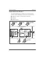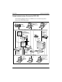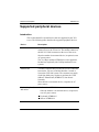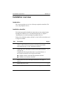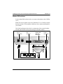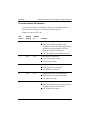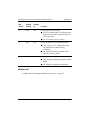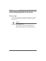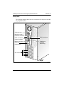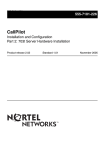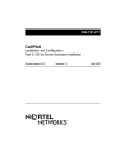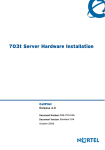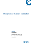
1
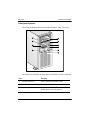
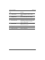
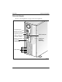
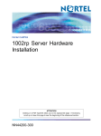
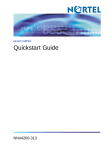
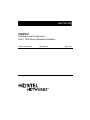
555-7101-215 555-7101-215 CallPilot Installation and Configuration Part 2: 702t Server Hardware Installation Product release 2.02 Standard 1.0 May 2003 P0604536 CallPilot Installation and Configuration Part 2: 702t Server Hardware Installation Publication number: Product release: Document release: Date: 555-7101-215 2.02 Standard 1.0 May 2003 Copyright © 2003 Nortel Networks, All Rights Reserved Printed in Canada Information is subject to change without notice. Nortel Networks reserves the right to make changes in design or components as progress in engineering and manufacturing may warrant. The process of transmitting data and call messaging between the CallPilot server and the Meridian 1 switch or Succession CSE 1000 system is proprietary to Nortel Networks. Any other use of the data and the transmission process is a violation of the user license unless specifically authorized in writing by Nortel Networks prior to such use. Violations of the license by alternative usage of any portion of this process or the related hardware constitutes grounds for an immediate termination of the license and Nortel Networks reserves the right to seek all allowable remedies for such breach. This page and the following page are considered the title page, and contain Nortel Networks and third-party trademarks. *Nortel Networks, the Nortel Networks logo, the Globemark, and Unified Networks, BNR, CallPilot, DMS, DMS-100, DMS-250, DMS-MTX, DMS-SCP, DPN, Dualmode, Helmsman, IVR, MAP, Meridian, Meridian 1, Meridian Link, Meridian Mail, Norstar, SL-1, SL-100, Succession, Supernode, Symposium, Telesis, and Unity are trademarks of Nortel Networks. 3COM is a trademark of 3Com Corporation. ACCENT is a trademark of Accent Software International Ltd. AMDEK is a trademark of Amdek Corporation. AT&T is a trademark of American Telephone and Telegraph Corporation. ATLAS is a trademark of Quantum Corporation. ATRIA is a trademark of Pure Atria Corporation. BLACKBERRY is a trademark of Research in Motion Limited. CASEWARE is a trademark of Caseware International, Inc. CONTINUUS is a trademark of Continuus Software Corporation. CRYSTAL REPORTS is a trademark of Seagate Software Inc. DEFINITY is a trademark of Avaya Inc. DIALOGIC is a trademark of Dialogic Corporation. EUDORA is a trademark of Qualcomm. EXCHANGE.NET, INTERNET EXPLORER, LINKEXCHANGE, MICROSOFT, MICROSOFT EXCHANGE SERVER, MS-DOS, OUTLOOK, POWERPOINT, WINDOWS, WINDOWS MEDIA, and WINDOWS NT are trademarks of Microsoft Corporation. GROUPWISE and NOVELL are trademarks of Novell Inc. HITACHI is a trademark of Hitachi Limited. INTEL is a trademark of Intel Corporation. LOGITECH is a trademark of Logitech, Inc. NETSCAPE COMMUNICATOR is a trademark of Netscape Communications Corporation. PCANYWHERE is a trademark of Symantec Corporation. PROMARK and RHOBOT are trademarks of DMI Promark, Inc. RADISYS is a trademark of Radisys Corporation. SLR4, SLR5, and TANDBERG are trademarks of Tandberg Data ASA. SYBASE is a trademark of Sybase, Inc. UNIX is a trademark of X/Open Company Limited. US ROBOTICS, the US ROBOTICS logo, and SPORTSTER are trademarks of US Robotics. VOICEBRIDGE is a trademark of Voice Technologies Group Inc. Publication history May 2003 Standard 1.0 issue for CallPilot 2.02. Appendix A on the EMC emission level protection has been added to the document. Information on single-point grounding has been added to Chapter 3, “Installing the server and connecting the peripheral devices”. October 2002 Standard 1.0 of the CallPilot Installation and Configuration, Part 2: 702t Server Hardware Installation is issued for general release. Part 2: 702t Server Hardware Installation v Publication history vi Standard 1.0 CallPilot Contents 1 702t server description 9 Server features . . . . . . . . . . . . . . . . . . . . . . . . . . . . . . . . . . . . . . . . . . . . . . Slot assignments . . . . . . . . . . . . . . . . . . . . . . . . . . . . . . . . . . . . . . . . . . . . . IRQ mapping table . . . . . . . . . . . . . . . . . . . . . . . . . . . . . . . . . . . . . . . . . . . Network connectivity . . . . . . . . . . . . . . . . . . . . . . . . . . . . . . . . . . . . . . . . . Supported peripheral devices . . . . . . . . . . . . . . . . . . . . . . . . . . . . . . . . . . . 2 Preinstallation requirements 25 Installation overview. . . . . . . . . . . . . . . . . . . . . . . . . . . . . . . . . . . . . . . . . . Unpacking the 702t server . . . . . . . . . . . . . . . . . . . . . . . . . . . . . . . . . . . . . Removing the side panel. . . . . . . . . . . . . . . . . . . . . . . . . . . . . . . . . . . . . . . Inspecting the server interior . . . . . . . . . . . . . . . . . . . . . . . . . . . . . . . . . . . 3 Installing the server and connecting the peripheral devices Installing the server. . . . . . . . . . . . . . . . . . . . . . . . . . . . . . . . . . . . . . . . . . . Preparing the modem . . . . . . . . . . . . . . . . . . . . . . . . . . . . . . . . . . . . . . . . . Connecting peripherals to the server . . . . . . . . . . . . . . . . . . . . . . . . . . . . . Connecting the server to the ELAN . . . . . . . . . . . . . . . . . . . . . . . . . . . . . . Connecting the server to the CLAN (optional). . . . . . . . . . . . . . . . . . . . . . Installing the Nortel Networks software feature key adapter . . . . . . . . . . . Connecting the server to power . . . . . . . . . . . . . . . . . . . . . . . . . . . . . . . . . A EMC emission level protection for the 702t Server Index Part 2: 702t Server Hardware Installation 10 14 17 19 24 26 29 31 34 37 38 39 43 46 48 50 52 57 Index 59 vii Contents viii Standard 1.0 CallPilot Chapter 1 702t server description In this chapter Server features 10 Slot assignments 14 IRQ mapping table 17 Network connectivity 19 Supported peripheral devices 24 Part 2: 702t Server Hardware Installation 9 702t server description Standard 1.0 Server features Introduction This section provides a general overview of the 702t server. Server dimensions Height 49 cm (19.3 in.) Width 21 cm (8.3 in.) (chassis), or 25 cm (10 in.) with feet Depth (distance from front to back) 45 cm (17.75 in.) Clearance front 21.59 cm (8.5 in.) Clearance rear 12.70 cm (5 in.) Clearance side 7.62 cm (3 in.). You require additional side clearance for service. Weight of fully loaded system with 22.05 kg (48.50 lb) 6 SCSI drives 6 populated boards CD-ROM floppy tape drives 10 CallPilot May 2003 702t server description Front panel features The following diagram shows the front panel features of the 702t server: 2a 1 2b 2 2c 3 4 5 6a 6 G100823 The table below describes the parts that are identified in the above diagram. Part Function 1. Backup tape drive Allows backup of hard drive data. 2. CD-ROM drawer Holds CD-ROM disk. 2a. Drawer push button To open the CD-ROM drawer; push the button again to close the drawer. Part 2: 702t Server Hardware Installation 11 702t server description Part Standard 1.0 Function 2b. Volume control Controls headphone volume for audio output. 2c. Headphone jack Jack for audio output from CD-ROM. 3. ON/OFF push button Turns the server’s power on or off. 4. Reset push button Momentarily disconnects the power to the server. Do not use for restart; use the software restart instead. 5. Indicator lights Indicate when the server is powered up and the disk drives are active. 6. Floppy drive Drive for 3 1/2” disks. 6a. Floppy eject button Ejects the floppy disk. 12 CallPilot May 2003 702t server description Rear panel diagram Refer to “Slot assignments” on page 14 for slot assignments. AC power input Mouse connector Keyboard connector COM 2 serial port COM 1 serial port (used for modem) Monitor connector Parallel port (software feature key) On-board network card Slot number 5 4 3 2 1 G101719 Part 2: 702t Server Hardware Installation 13 702t server description Standard 1.0 Slot assignments Introduction The slot assignment tables show the following: the physical location of boards inside the server, relative to other boards the order in which boards are installed (for example, board #1, 2, 3, and so on) how the boards are represented in CallPilot Manager applications (that is, on the Maintenance Administration page) the maximum capacity for each switch connectivity Note: Your server may vary depending on what was ordered from Nortel Networks. Therefore, your server may not have all of the slots populated. Slot definition and slot numbering In these tables, the term “slot” refers to the available slot openings in the chassis, not the PCI or ISA connectors inside the server. The slots are numbered from the bottom of the server to the top. Slot 1 is the bottom slot in the chassis if the chassis is standing on its feet. 14 CallPilot May 2003 702t server description Slot assignments: 702t server with RAID CallPilot-assigned Slot number board label a Onboard network cardb Meridian 1 Succession CSE 1000 ELAN Network card ELAN Network card Slot 5 BRD05 RAID RAID Slot 4 BRD04 CLAN Network card CLAN Network card Slot 3 BRD03 MPB16-4 board #2 (optional) MPB16-4 board #2 (optional) Slot 2c BRD02 MPB16-4 board #1 MPB16-4 board #1 Slot 1 BRD01 Not used Not used a. In some CallPilot Manager applications, the CallPilot-assigned board label appears. This label corresponds to the slot number. For example, BRD05 refers to the board in slot 5. b. The onboard network card is built onto the motherboard. This card does not have a slot. c. For Meridian 1 and Succession CSE 1000, the first MPB16-4 board must be installed in slot 2. Part 2: 702t Server Hardware Installation 15 702t server description Standard 1.0 Slot assignments: 702t server without RAID CallPilot-assigned Slot number board label Onboard network cardb a Meridian 1 Succession CSE 1000 ELAN Network card ELAN Network card Slot 5 BRD05 Not used Not used Slot 4 BRD04 CLAN Network card CLAN Network card Slot 3 BRD03 MPB16-4 board #2 (optional) MPB16-4 board #2 (optional) Slot 2c BRD02 MPB16-4 board #1 MPB16-4 board #1 Slot 1 BRD01 Not used Not used a. In some CallPilot Manager applications, the CallPilot-assigned board label appears. This label corresponds to the slot number. For example, BRD05 refers to the board in slot 5. b. The onboard network card is built onto the motherboard. This card does not have a slot. c. For Meridian 1 and Succession CSE 1000, the first MPB16-4 board must be installed in slot 2. 16 CallPilot May 2003 702t server description IRQ mapping table The following table lists the assignments for each Interrupt Request (IRQ). You do not need this information for installation, but it may be useful for troubleshooting. IRQ Slot or device 0 Timer 1 Chipset 2 System/unused 3 Serial Port 2 (COM2) 4 Serial Port 1 (COM1) 5 For Meridian 1 or Succession CSE 1000 system, available for CLAN in slot 4 as needed. 6 Floppy controller 7 Parallel port (LPT1) 8 Real Time Clock 9 ACPI SCI Interrupt 10 On-board network card 11 Slots 2 and 3 (MPB16-4 boards) 12 PS/2 Mouse 13 Math coprocessor 14 Primary EIDE controller Part 2: 702t Server Hardware Installation 17 702t server description IRQ Slot or device 15 Slot 5 (RAID/On-Board SCSI controllers) Standard 1.0 Note: Both SCSI controllers are on IRQ 15, which allows the SSU to automatically resolve any IRQ conflict. 18 CallPilot May 2003 702t server description Network connectivity Introduction This section describes how the 702t server can be integrated into your network. The integration depends on the type of switch you are using. ATTENTION To secure the CallPilot server from unauthorized access, ensure that the CallPilot network is inside your organization’s firewall. Part 2: 702t Server Hardware Installation 19 702t server description Standard 1.0 Sample network setup: Meridian 1 The following diagram shows a CallPilot server network setup with a Meridian 1 switch. The Meridian 1 switch can be one of the following: Option 11C or Option 11C Mini using fiber connections Option 51C Option 61C Options 81 and 81C Desktop client PC Desktop client PC Web-enabled administrative PC Customer LAN (optional) Modem CallPilot server Meridian 1 switch Router or Ethernet switch (optional) MPB16-4 board MGate card Embedded LAN Laptop Web-enabled administrative PC G101626 20 CallPilot May 2003 702t server description Sample network setup: Succession CSE 1000 The following diagram shows a CallPilot server network setup with a Succession CSE 1000 system: Web-enabled CallPilot administrative PC i2004 Internet phonesets Desktop client PC Telephony LAN/Customer LAN (10/100BaseT or 100BaseT) Internet Telephony Gateway Line Card Succession CSE 1000 Media Gateway Expansion Modem CallPilot server CE-MUX DS-30x Internet Telephony Gateway Line Card Succession CSE 1000 Call Server Router or Ethernet switch (optional) Succession CSE 1000 Media Gateway MGate card MPB16-4 board Embedded LAN (10BaseT) Optivity Telephony Manager PC Laptop Web-enabled CallPilot administrative PC G101636 Part 2: 702t Server Hardware Installation 21 702t server description Standard 1.0 In this illustration, the telephony LAN (TLAN) provides IP connectivity between the Succession CSE 1000 system and the i2004 Internet phonesets. The connection between the Call Server and Media Gateway can be pointto-point, or it can be through the LAN, if the system is installed in a distributed data network. For information about the Succession CSE 1000 system and i2004 Internet phoneset bandwidth and network requirements, refer to the Succession Communication Server for Enterprise 1000 Planning and Installation Guide (NTP 553-3023-210). Switch connectivity For more details about how the 702t server and switch connection is established, refer to Part 3 in the CallPilot Installation and Configuration binder. LAN connectivity The 702t server provides 10/100Base-T Ethernet network connectivity. See “Rear panel diagram” on page 13 and “Slot assignments” on page 14 for details on the location of network interface cards. The function of each network interface card is described below: An Ethernet controller on the server’s motherboard provides connectivity to the ELAN. For information about the ELAN’s purpose and requirements, see “About the ELAN” in Part 1 of the CallPilot Installation and Configuration binder. An optional network interface card (NIC) is installed in the server. This optional NIC is required only for Meridian 1 or Succession CSE 1000 systems that require a CLAN connection (in addition to the ELAN connection). The CLAN provides data connectivity between desktop and web messaging clients and the CallPilot server. 22 CallPilot May 2003 702t server description Network requirements Appropriate networking equipment must be available for both the CLAN and ELAN. The CLAN and ELAN must be properly configured for correct CallPilot operation. To ensure correct configuration, Nortel Networks recommends that you consult a network specialist. ATTENTION For important considerations about using the ELAN in your network, see “About the ELAN” in Part 1 of the CallPilot Installation and Configuration binder. Remote access connectivity The RS-232 COM 1 connector on the rear of the 702t server provides the connection to an external high-speed modem. The modem allows administrators and technical support personnel to administer the 702t server from a remote location. pcAnywhere is used to establish the remote access connection to the server. Part 2: 702t Server Hardware Installation 23 702t server description Standard 1.0 Supported peripheral devices Introduction This section identifies external devices that are supported by the 702t server. The following table describes the supported peripheral devices: Device Description Modem A 56 Kbps external modem (NTRH9078) provides remote access to the 702t server. The modem connects to the RS-232 COM1 connector on the rear of the server. Since the modem is an external device, it requires its own AC power source. The 33.6 Kbps modem (NTRH9016) is also supported, but has been replaced by the 56 Kbps modem for new systems. Ethernet hub A 10BaseT Ethernet hub provides the ELAN connection between the 702t server and the Meridian 1 switch or Succession CSE 1000 system. The customer can supply a hub from third-party vendors or purchase the 3Com 10BaseT Ethernet hub (NTRH9017) from Nortel Networks. Since the hub is an external device, it requires an AC power source. Monitor, keyboard, and mouse 14" monitor: NTRH9011 Since the monitor is an external device, it requires its own AC power source. Keyboard: NTRH9013 Mouse: NTRH9014 24 CallPilot Chapter 2 Preinstallation requirements In this chapter Installation overview 26 Unpacking the 702t server 29 Removing the side panel 31 Inspecting the server interior 34 Part 2: 702t Server Hardware Installation 25 Preinstallation requirements Standard 1.0 Installation overview Introduction This section provides an overview of the steps required to install the 702t server and peripheral devices. Installation checklist The following checklist identifies the tasks that must be performed when installing the CallPilot server. For detailed instructions, see Chapter 3, “Installing the server and connecting the peripheral devices.” When you are finished, continue with Part 3 of the CallPilot Installation and Configuration binder. Step Description Check 1 Ensure that you have reviewed the “Installing CallPilot” section in Part 1 of the CallPilot Installation and Configuration binder, and completed stage 1 of the “Installation checklist.” ❒ 2 Unpack the server, and ensure you have all the items you need (see page 29). ❒ Complete the following checklists that are provided in Part 1 of the CallPilot Installation and Configuration binder: “CallPilot software media and documentation checklist” “CallPilot server hardware checklist” 3 Remove the server cover, and inspect the interior (see pages 31 and 34). ❒ 4 Replace the server cover. ❒ 5 Place the 702t server in the chosen location (see page 38). ❒ 26 CallPilot May 2003 Preinstallation requirements Step Description Check 6 Set the DIP switches on the modem (see page 41). ❒ 7 Connect the 702t server and devices as follows: ❒ Connect the monitor, keyboard, and mouse (see page 43). ❒ Connect the modem (see page 45). ❒ Connect the 702t server to the ELAN hub (see page 46). ❒ Connect the 702t server to the CLAN hub (optional); (see ❒ page 48). Install the software feature key adapter (see page 50). ❒ Connect the power cords for all devices, and then power ❒ them up. 8 Start the 702t server (see page 54). Part 2: 702t Server Hardware Installation ❒ 27 Preinstallation requirements Standard 1.0 Conventions for warnings You may encounter the following types of warnings in this guide. Do not ignore them. DANGER Risk of electric shock . Warns you of an immediate electrical hazard, which, if not avoided, will result in shock, serious injury, or death. WARNING Risk of personal injury . Warns you of a situation in which you can be injured if instructions are not followed exactly as stated. CAUTION Risk of equipment damage . ATTENTION 28 Alerts you to situations where data can be lost or damaged, equipment can be damaged, actions can result in service interruption, and productive time can be lost. Provides information that is essential to the completion of a task. CallPilot May 2003 Preinstallation requirements Unpacking the 702t server Introduction Follow this procedure to unpack the server and peripherals. WARNING Risk of personal injury . The 702t CallPilot server weighs approximately 17 kg (38 lb) as shipped from manufacturing. To prevent personal injury, ask someone to help you unpack and position the server. To unpack the equipment ATTENTION As you unpack each item, check it off against the packing list, as well as against the following checklists provided in Part 1 of the CallPilot Installation and Configuration binder: “CallPilot software media and documentation checklist” “CallPilot server hardware checklist” 1 Carefully open the cardboard carton containing the server. 2 Remove the server from the carton and set it on the floor. 3 Carefully open the cartons containing the monitor, keyboard, mouse, modem, and ELAN hub (if supplied), and set the peripherals aside. 4 Put all manuals, CD-ROMs, operating system disks, any disks for peripherals, and the Windows NT emergency repair disk in a safe place. 5 Save all packing materials and cartons in case you must return any equipment to the carrier. Part 2: 702t Server Hardware Installation 29 Preinstallation requirements Standard 1.0 What’s next? Remove the server cover so that you can inspect the interior of the server. See “Removing the side panel” on page 31. 30 CallPilot May 2003 Preinstallation requirements Removing the side panel To remove the side panel WARNING Risk of personal injury . Be careful when you handle the sharp edges of the side panel and chassis to prevent personal injury. CAUTION Risk of equipment damage . Use an ESD wrist strap to protect static-sensitive components. The following diagram shows how to remove the side panel. See the instructions for removal on page 32 . Part 2: 702t Server Hardware Installation 31 Preinstallation requirements Standard 1.0 A C B Bottom tabs of cover Bottom slots of chassis G100825 Note: The illustration shows a customer-supplied padlock (A). 1 If a padlock is installed on the back of the system, unlock and remove it. Refer to “A” in the illustration. 2 Remove and save the three screws from the back of the side cover. Refer to “B” in the illustration. Note: You need the screws to reattach the side cover. 3 Place the fingertips of your left hand under the built-in handle on the back of the cover. 4 Pull the cover approximately 2.5 cm (1 in.) away from the front of the server until it stops. Refer to “C” in the illustration. 32 CallPilot May 2003 Preinstallation requirements 5 Use your left hand to pull the back end of the cover toward you to disengage the bottom row of tabs from the notches in the chassis, as shown in the diagram on page 32. 6 Use both hands to lift the cover upward to disengage the top row of tabs from the notches in the top edge of the chassis. 7 Set the cover aside. Part 2: 702t Server Hardware Installation 33 Preinstallation requirements Standard 1.0 Inspecting the server interior Introduction You should perform a visual inspection for loose components, foreign matter, or shipping damage inside the server. CAUTION Risk of equipment damage . When working with interior components, use an ESD wrist strap to protect static-sensitive components. Protective foam The server is shipped with protective foam to prevent damage during shipping. You must remove the foam before you inspect the server and continue with the installation. The foam can be stored for future use in case you need to ship the server back to the distributor or to Nortel Networks. CAUTION Risk of equipment damage . The server can be damaged if the protective foam is not removed and the server is powered up. Do not power up the server while the protective foam is in the server. To remove protective foam and inspect the server interior 1 Carefully remove the foam from inside the chassis. 2 Ensure that all the cards are fully seated on the baseboard. 3 Check for any loose wires or foreign objects, such as loose screws, inside the chassis. 34 CallPilot May 2003 Preinstallation requirements 4 Review the slot locations (see “Rear panel diagram” on page 13). 5 Do one of the following: IF THEN you observe any damage contact your Nortel Networks technical support representative. components have become loose secure them. Then replace the server cover and proceed with the hardware installation. Refer to the procedures in Part 5 of the CallPilot Installation and Configuration binder. you are satisfied that the 702t server has arrived at your site undamaged Part 2: 702t Server Hardware Installation replace the server cover and proceed with the hardware installation. See “Installation checklist” on page 26. 35 Preinstallation requirements 36 Standard 1.0 CallPilot Chapter 3 Installing the server and connecting the peripheral devices In this chapter Installing the server 38 Preparing the modem 39 Connecting peripherals to the server 43 Connecting the server to the ELAN 46 Connecting the server to the CLAN (optional) 48 Installing the Nortel Networks software feature key adapter 50 Connecting the server to power 52 Part 2: 702t Server Hardware Installation 37 Installing the server and connecting the peripheral devices Standard 1.0 Installing the server Introduction Before you install the 702t server, ensure that the chosen location meets the requirements identified on the “Site inspection checklist” provided in Part 1 of the CallPilot Installation and Configuration binder. To install the server Place the 702t server in its chosen location. Connect peripheral devices as described in the remainder of this chapter. ATTENTION 38 Do not connect the server to power yet. CallPilot May 2003 Installing the server and connecting the peripheral devices Preparing the modem Introduction You require a modem to support remote dial-up access to the CallPilot server. The modem also enables Nortel Networks technical support to connect to your CallPilot server for troubleshooting purposes. Nortel Networks connects to your server only when you request technical assistance. Required equipment To install the modem, you need the following equipment: an analog external modem that includes an RJ-11 analog phone cord a power adapter cord One of the following modems may have been provided with your server: U.S. Robotics 33.6 Kbps modem (NTRH9016) U.S. Robotics 56 Kbps modem (NTRH9078) a 25-pin male to 9-pin female shielded serial cable for your modem Note: Ensure that you have the correct cable for your modem, as follows: 33.6 Kbps modem: A0601464 56 Kbps modem: A0841984 an analog line jack tweezers, or a screw driver small enough to use to adjust the DIP switches Part 2: 702t Server Hardware Installation 39 Installing the server and connecting the peripheral devices Standard 1.0 Modem DIP switches Set the modem DIP switches before you connect the modem to the CallPilot server. Note: This section applies only to the US Robotics 33.6 or 56 Kbps external Sportster modem. If your modem is different, refer to the documentation for your modem. The following diagram shows the key components of the external modem, including the location and required settings of the DIP switches: RJ-11 connection DIP switches Serial cable (RS-232) connection Power connection 1 2 3 4 5 6 7 8 Switch positions: OFF ON 1 2 3 4 5 6 7 8 G101445 40 CallPilot May 2003 Installing the server and connecting the peripheral devices To set the modem DIP switches Use a pair of tweezers or a small screw driver to set the DIP switches as described in the “Change to” column of the following table: Note: ON is down. OFF is up. DIP switch Default setting Change to Function 1 OFF OFF Data Terminal Ready (DTR) override OFF: Normal DTR operations. (The computer must provide a DTR signal for the modem to accept commands. If DTR is dropped, the call is terminated.) ON: The modem ignores DTR (override). 2 OFF OFF Verbal/numeric result codes OFF: Verbal (word) results. ON: Numeric results. 3 ON ON Result code display OFF: Suppresses result codes. ON: Enables result codes. 4 OFF OFF Command mode local echo suppression OFF: Displays keyboard commands. ON: Suppresses echo. 5 ON ON Auto answer suppression OFF: The modem answers on the first ring, or higher if specified in NVRAM. ON: Disables auto answer. Part 2: 702t Server Hardware Installation 41 Installing the server and connecting the peripheral devices DIP switch Default setting Change to Function 6 OFF OFF Carrier Detect (CD) override Standard 1.0 OFF: The modem sends a CD signal when it connects with another modem; it drops the CD on disconnect. ON: CD is always ON (override). 7 OFF OFF Power-on and ATZ reset software defaults OFF: Loads Y or Y1 configuration from user-defined non-volatile memory (NVRAM). ON: Loads &F0-Generic template from read-only memory (ROM). 8 ON ON AT command set recognition OFF: Disables command recognition (dumb mode). ON: Enables recognition (smart mode). What’s next? Continue with “Connecting peripherals to the server” on page 43. 42 CallPilot May 2003 Installing the server and connecting the peripheral devices Connecting peripherals to the server Before you begin A legend is located adjacent to the peripheral connector panel at the back of the server. This legend shows the symbol for each peripheral and which connector to use. CAUTION Risk of system failure . You can install or use only Nortel Networks-approved peripheral devices on your server. Installation or use of unapproved peripheral devices can result in system failure. Part 2: 702t Server Hardware Installation 43 Installing the server and connecting the peripheral devices Standard 1.0 Rear panel The following diagram shows the server connectors for the power cord and the peripheral devices: AC power input Mouse connector Keyboard connector COM 2 serial port COM 1 serial port (used for modem) Monitor connector Parallel port (software feature key) On-board network card Slot number 5 4 3 2 1 G101719 44 CallPilot May 2003 Installing the server and connecting the peripheral devices To connect the mouse, keyboard, and monitor to the server 1 Place the monitor, keyboard, and mouse in the same location as the server. 2 Plug the keyboard and mouse into the appropriate PS/2 connectors on the chassis rear panel. See the diagram on page 44. 3 Plug in the monitor connector. Tighten the screws on the connector. 4 Connect the power cord to the monitor, and plug the other end into a wall receptacle or power bar. 5 Turn on the monitor. To connect the modem to the server 1 Ensure that the modem’s AC power cord is not plugged in. 2 Connect the large 25-pin male connector to the back of the modem. Tighten the connector screws. 3 Connect the 9-pin female connector to COM1 at the rear of the server. Tighten the connector screws. 4 Connect one end of the telephone cable to the modem RJ-11 jack labeled LINE. 5 Connect the other end of the telephone cable to the RJ-11 jack in the wall. 6 Connect the power cord to the modem, and plug the other end into a wall receptacle or power bar. 7 Turn on the modem. What’s next? Continue with “Connecting the server to the ELAN” on page 46. Part 2: 702t Server Hardware Installation 45 Installing the server and connecting the peripheral devices Standard 1.0 Connecting the server to the ELAN Introduction Connect the CallPilot server to the Meridian 1 switch or Succession CSE 1000 system using the Embedded LAN (ELAN). ATTENTION For important considerations about using the ELAN in your network, see “About the ELAN” in Part 1 of the CallPilot Installation and Configuration binder. Media Access Control address The Media Access Control (MAC) address is a unique number assigned to network cards and controllers. The procedure below asks you to record the MAC address from the label affixed to the ELAN network card faceplate. The network card faceplate is visible through the slot openings in the back of the chassis. To connect the server to the ELAN 1 See the diagram on page 44 to locate the on-board network card connector. This is the ELAN connector. 2 Locate the label on the ELAN network card faceplate that identifies the ELAN controller’s MAC address. Note: This label is affixed to the chassis rear panel. 3 Record the MAC address on the Configuration Wizard worksheet that is provided in Part 1 of the CallPilot Installation and Configuration binder. You need the MAC address to identify the ELAN when running the Configuration Wizard to configure the CallPilot server. 46 CallPilot May 2003 Installing the server and connecting the peripheral devices 4 Connect an RJ-45 network cable from the ELAN hub to the ELAN connector on the server. Note: The ELAN hub is optional if you use a cross-over network cable to make a direct point-to-point connection from the server to the switch. However, if you choose to establish a direct point-to-point ELAN connection, no other device can connect to the ELAN. 5 At the switch, connect the ELAN network cable to an MAU (Ethernet) transceiver. Then complete the connection from the transceiver to the switch. DANGER Risk of fire hazard . MAU model NTRH9069 is not suitable for installation in ducts, plenums, or other spaces used for environmental air. Do not install it above a false ceiling or below a raised floor, unless it can be confirmed that these spaces are not used to convey environmental air. What’s next? IF the server will THEN be connected to a CLAN continue with page 48. not be connected to a CLAN continue with installing the software feature key adapter (dongle). See page 50. Part 2: 702t Server Hardware Installation 47 Installing the server and connecting the peripheral devices Standard 1.0 Connecting the server to the CLAN (optional) Introduction This section provides instructions to connect the server to the Customer LAN (CLAN). Note: The CLAN is optional. However, a CLAN is required to support desktop and web messaging users. Media Access Control address The Media Access Control (MAC) address is a unique number assigned to network cards and controllers. The procedure below asks you to record the MAC address from the label affixed to the CLAN network card faceplate. The network card faceplate is visible through the slot openings in the back of the chassis. To connect the server to the CLAN 1 See the diagram on page 44 to locate slot 4. The CLAN card is in slot 4. 2 Locate the label on the CLAN network card faceplate that identifies the CLAN controller’s MAC address. 3 Record the MAC address on the Configuration Wizard worksheet that is provided in Part 1 of the CallPilot Installation and Configuration binder. You need the MAC address to identify the CLAN when running the Configuration Wizard to configure the CallPilot server. 4 Connect an RJ-45 network cable from the CLAN hub to the CLAN connector. 48 CallPilot May 2003 Installing the server and connecting the peripheral devices What’s next? Continue with “Installing the Nortel Networks software feature key adapter” on page 50. Part 2: 702t Server Hardware Installation 49 Installing the server and connecting the peripheral devices Standard 1.0 Installing the Nortel Networks software feature key adapter Introduction The software feature key is a security device that stores the unique serial number of the server. The feature key is embedded in the Nortel Networks software feature key adapter, which plugs into the parallel port. An illustration of the software feature key embedded in the software feature key adapter is shown below: Software feature key G101738 50 CallPilot May 2003 Installing the server and connecting the peripheral devices Requirements For installation, you require a Phillips No. 1 screwdriver. To install the software feature key adapter 1 Ensure that there is no cable connected to the parallel port. Note: The parallel port is also known as the printer port or LPT1. It is located at the back of the server. See the diagram on page 44. 2 Plug the male end of the adapter into the parallel port. 3 Tighten the connector screws. What’s next? Continue with “Connecting the server to power” on page 52. Part 2: 702t Server Hardware Installation 51 Installing the server and connecting the peripheral devices Standard 1.0 Connecting the server to power Before you begin Ensure that proper power and grounding are available for all the power outlets serving the CallPilot server and its associated peripherals. Power for these devices must be wired and fused independently of all other receptacles and referenced to the same ground as the PBX system. A qualified electrician must implement the single-point ground reference as required between the power outlets of the CallPilot server and the power outlets of the switch. Provide a sufficient number of properly grounded power outlets or power bars for all equipment. For more information, refer to Chapter 2, “Grounding and power requirements”, in the CallPilot Planning and Engineering Guide. 52 CallPilot May 2003 Installing the server and connecting the peripheral devices Before you connect the server to the power source, review the following diagram to ensure that all peripheral hardware devices are in place. CallPilot server Mouse RJ-45 RJ-45 RS-232 Monitor ELAN hub (M1 or CSE 1000 only) CLAN hub (optional) Modem AC power AC power AC power AC power Keyboard AC power source G101637 Part 2: 702t Server Hardware Installation 53 Installing the server and connecting the peripheral devices Standard 1.0 To connect the server to power CAUTION Risk of hardware failure . The power outlets that are used by the CallPilot server and its peripheral devices must be connected to the same ground reference as the one used by the Meridian 1 switch or Succession CSE 1000 system with MGate cards connected to the CallPilot server. If this requirement is not met, power transients can cause hardware failure. 1 Plug the server’s AC power cord into the server’s rear panel. 2 Plug the other end of the server’s AC power cord into a properly grounded power outlet or power bar. To start the server 1 Press the server’s power switch to start the server. 2 Observe the Power-On Self-Test (POST) and initialization messages on the monitor. 3 When the following menu appears on the monitor, select option 1 to boot Windows NT: Select one of the following: --------------------------1 Windows NT 4.0 Server (Default within 30 secs) 2 Windows NT 4.0 Server (VGA mode) Choose an option[1,2]?1 The Windows NT startup sequence begins. 4 Ensure that the Windows NT logon window appears on the monitor. Note: If the Windows NT logon window does not appear, refer to Part 5 of the CallPilot Installation and Configuration binder for troubleshooting instructions. 54 CallPilot May 2003 Installing the server and connecting the peripheral devices What’s next? If Windows NT started successfully, proceed with the switch and server set up as described in Part 3 of the CallPilot Installation and Configuration binder. Part 2: 702t Server Hardware Installation 55 Installing the server and connecting the peripheral devices 56 Standard 1.0 CallPilot May 2003 EMC emission level protection for the 702t Server Appendix A EMC emission level protection for the 702t Server To lower the EMC emission level, ferrite cores are installed with one loop (see diagram below) on the following external cables: Ferrite Core (TDK and part number ZCAT3035-1330) - for the single DS30X I/O cable (Nortel Networks and part number NTRH2012), at each end of the cable Ferrite Core (TDK and part number ZCAT3035-1330) - for the dual DS30X I/O cable (Nortel Networks and part number NTRH2013), at each end of the cable CAUTION . Risk of equipment damage These ferrite cores are pre-installed on these customer provided cables. It is not the customer’s responsibility to attach these ferrite cores to these cables. However, the customer should ensure that these ferrites are in place to keep the EMC emission levels low. Part 2: 702t Server Hardware Installation 57 EMC emission level protection for the 702t Server Standard 1.0 Ferrites secured to an external cable The ferrites are secured to the appropriate cable with plastic enclosure clips. Ty wraps are added to the cable loop. 58 CallPilot Index A adapter software feature key, illustration 50 assigned board label CallPilot Manager 15 C cable, multi I/O connections RS-232 23 CLAN media access control address 48 CLAN network card faceplate 48 COM1 connection, description 23 connecting peripherals to the server 43 connecting the server 52 connections COM1, description 23 connectivity Ethernet 22 remote 23 Customer LAN see CLAN 48 connection network, M1 and CallPilot server 20 network, Succession CSE and CallPilot server 21 front panel, parts of 11 server connections for the power cord and peripherals 43 DIP switches modem, function 41 DIP switches, setting modem 41 dongle 50 E ELAN Media Access Control address 46 equipment unpacking instructions 29 F fax modem illustration 40 required equipment 39 front panel 11 D devices, peripheral 24 keyboard 24 monitor 24 mouse 24 diagram Part 2: 702t Server Hardware Installation I illustration modem 40 rear panel, server connectors 44 59 Index Standard 1.0 software feature key adapter 50 TLAN 21 IRQ mapping table 17 P K keyboard connecting to the server 45 description 24 keylock 50 M M1 and CallPilot server network diagram 20 MAC address CLAN 48 ELAN 46 modem connecting to the server 45 DIP switches, setting 41 illustration 40 required equipment 39 monitor connecting to the server 45 description 24 mouse connecting to the server 45 description 24 MPB16-4 board slot number for M1 15, 16 slot number for Succession CSE 1000 15, 16 multi I/O cable description RS-232 connection 23 N network protocols,supported 22 network interface cards 22 60 NIC See network interface cards part numbers keyboard 24 monitor 24 mouse 24 peripheral devices 24 keyboard 24 monitor 24 mouse 24 peripherals connecting to the server 43 protective foam removal of 34 protocols, supported network 22 R rear panel server connectors 44 rear panel diagram, parts of 13 remote access connectivity 23 RS-232 connection 23 S serial number of the server 50 server connecting peripherals 43 power connection 52 serial number 50 server interior inspection 34 server with RAID slot assignments 15 server without RAID slot assignments 16 CallPilot May 2003 Index setting modem DIP switches 41 side panel removing 31 side panel removal diagram 32 slot assignments server with RAID 15 without RAID 16 slot locations diagram 13 software feature key 50 Succession CSE 1000 and CallPilot server network diagram 21 switches, setting DIP modem 41 T telephony LAN See TLAN TLAN illustration 21 U unpacking instructions equipment 29 Part 2: 702t Server Hardware Installation 61 Index 62 Standard 1.0 CallPilot CallPilot Installation and Configuration Part 2: 702t Server Hardware Installation Copyright © 2003 Nortel Networks, All Rights Reserved Information is subject to change without notice. Nortel Networks reserves the right to make changes in design or components as progress in engineering and manufacturing may warrant. The process of transmitting data and call messaging between the CallPilot server and the Meridian 1 switch or Succession CSE 1000 system is proprietary to Nortel Networks. Any other use of the data and the transmission process is a violation of the user license unless specifically authorized in writing by Nortel Networks prior to such use. Violations of the license by alternative usage of any portion of this process or the related hardware constitutes grounds for an immediate termination of the license and Nortel Networks reserves the right to seek all allowable remedies for such breach. Publication number: Product release: Document release: Date: Printed in Canada 555-7101-215 2.02 Standard 1.0 May 2003