1
Part No. 312410-A Rev 00
November 2000
600 Technology Park Drive
Billerica, MA 01821-4130
Installing and Operating
AN/DC and ANH-8/DC
Systems
Copyright © 2000 Nortel Networks
All rights reserved. November 2000.
The information in this document is subject to change without notice. The statements, configurations, technical data,
and recommendations in this document are believed to be accurate and reliable, but are presented without express or
implied warranty. Users must take full responsibility for their applications of any products specified in this document.
The information in this document is proprietary to Nortel Networks NA Inc.
Trademarks
NORTEL NETWORKS is a trademark of Nortel Networks.
ACE, AFN, AN, BCN, BLN, BN, CN, FN, FRE, GAME, LN, Optivity, and PPX are registered trademarks and ANH,
ASN, Bay•SIS, BCNX, BLNX, EZ Install, EZ Internetwork, EZ LAN, PathMan, PhonePlus, Quick2Config,
RouterMan, and SPEX are trademarks of Nortel Networks.
Microsoft, MS, MS-DOS, Windows, and Windows NT are registered trademarks of Microsoft Corporation.
All other trademarks and registered trademarks are the property of their respective owners.
Statement of Conditions
In the interest of improving internal design, operational function, and/or reliability, Nortel Networks NA Inc. reserves
the right to make changes to the products described in this document without notice.
Nortel Networks NA Inc. does not assume any liability that may occur due to the use or application of the product(s)
or circuit layout(s) described herein.
USA Requirements Only
Federal Communications Commission (FCC) Compliance Notice: Radio Frequency Notice
Note: This equipment has been tested and found to comply with the limits for a Class A digital device, pursuant to
Part 15 of the FCC rules. These limits are designed to provide reasonable protection against harmful interference
when the equipment is operated in a commercial environment. This equipment generates, uses, and can radiate radio
frequency energy. If it is not installed and used in accordance with the instruction manual, it may cause harmful
interference to radio communications. Operation of this equipment in a residential area is likely to cause harmful
interference, in which case users will be required to take whatever measures may be necessary to correct the
interference at their own expense.
European Requirements Only
EN 55 022 Statement
This is to certify that the Nortel Networks BN router is shielded against the generation of radio interference in
accordance with the application of Council Directive 89/336/EEC, Article 4a. Conformity is declared by the
application of EN 55 022 Class A (CISPR 22).
Warning: This is a Class A product. In a domestic environment, this product may cause radio interference, in which
case, the user may be required to take appropriate measures.
Achtung: Dieses ist ein Gerät der Funkstörgrenzwertklasse A. In Wohnbereichen können bei Betrieb dieses Gerätes
Rundfunkstörungen auftreten, in welchen Fällen der Benutzer für entsprechende Gegenmaßnahmen verantwortlich
ist.
Attention: Ceci est un produit de Classe A. Dans un environnement domestique, ce produit risque de créer des
interférences radioélectriques, il appartiendra alors à l’utilisateur de prendre les mesures spécifiques appropriées.
ii
312410-A Rev 00
EC Declaration of Conformity
This product conforms (or these products conform) to the provisions of Council Directive 89/336/EEC and
73/23/EEC.
Japan/Nippon Requirements Only
Voluntary Control Council for Interference (VCCI) Statement
Taiwan Requirements
Bureau of Standards, Metrology and Inspection (BSMI) Statement
Canada Requirements Only
Canadian Department of Communications Radio Interference Regulations
This digital apparatus (BN router) does not exceed the Class A limits for radio-noise emissions from digital apparatus
as set out in the Radio Interference Regulations of the Canadian Department of Communications.
Règlement sur le brouillage radioélectrique du ministère des Communications
Cet appareil numérique (BN router) respecte les limites de bruits radioélectriques visant les appareils numériques de
classe A prescrites dans le Règlement sur le brouillage radioélectrique du ministère des Communications du Canada.
Canada CS-03 Rules and Regulations
Notice: The Industry Canada label identifies certified equipment. This certification means that the equipment meets
telecommunications network protective, operational and safety requirements as prescribed in the appropriate Terminal
Equipment Technical Requirements document(s). The Department does not guarantee the equipment will operate to
the user’s satisfaction.
Before installing this equipment, users should ensure that it is permissible to be connected to the facilities of the local
telecommunications company. The equipment must also be installed using an acceptable method of connection. The
customer should be aware that compliance with the above conditions may not prevent the degradation of service in
some situations.
312410-A Rev 00
iii
Canada Requirements Only (continued)
Repairs to certified equipment should be coordinated by a representative designated by the supplier. Any repairs or
alterations made by the user to this equipment, or equipment malfunctions, may give the telecommunications
company cause to request the user to disconnect the equipment.
Users should ensure for their own protection that the electrical ground connections of the power utility, telephone lines
and internal metallic water pipe system, if present, are connected together. This precaution may be particularly
important in rural areas.
Caution: Users should not attempt to make such connections themselves, but should contact the appropriate electric
inspection authority, or electrician, as appropriate.
Notice: For equipment using loopstart lines, please note that the Ringer Equivalence Number (REN) assigned to each
terminal device provides an indication of the maximum number of terminals allowed to be connected to a telephone
interface. The termination on an interface may consist of any combination of devices subject only to the requirement
that the sum of the Ringer Equivalence Numbers of all the devices does not exceed 5. The REN is located on the “FCC
Rules Part 68” label located on the bracket of the module, or on the back of the unit.
Canada CS-03 -- Règles et règlements
Avis: L'étiquette d'Industrie Canada identifie le matériel homologué. Cette étiquette certifie que le matériel est
conforme aux normes de protection, d'exploitation et de sécurité des réseaux de télécommunications, comme le
prescrivent les documents concernant les exigences techniques relatives au matériel terminal. Le Ministère n'assure
toutefois pas que le matériel fonctionnera à la satisfaction de l'utilisateur.
Avant d'installer ce matériel, l'utilisateur doit s'assurer qu'il est permis de le raccorder aux installations de l'entreprise
locale de télécommunication. Le matériel doit également être installé en suivant une méthode acceptée de
raccordement. L'abonné ne doit pas oublier qu'il est possible que la conformité aux conditions énoncées ci-dessus
n'empêche pas la dégradation du service dans certaines situations.
Les réparations de matériel homologué doivent être coordonnées par un représentant désigné par le fournisseur.
L'entreprise de télécommunications peut demander à l'utilisateur de débrancher un appareil à la suite de réparations ou
de modifications effectuées par l'utilisateur ou à cause de mauvais fonctionnement.
Pour sa propre protection, l'utilisateur doit s'assurer que tous les fils de mise à la terre de la source d'énergie électrique,
des lignes téléphoniques et des canalisations d'eau métalliques, s'il y en a, sont raccordés ensemble. Cette précaution
est particulièrement importante dans les régions rurales.
Avertissement: L'utilisateur ne doit pas tenter de faire ces raccordements lui-même; il doit avoir recours à un service
d'inspection des installations électriques, ou à un électricien, selon le cas.
Avis: Veuillez prendre note que pour tout appareillage supportant des lignes de type “loopstart,” l'indice d'équivalence
de la sonnerie (IES) assigné à chaque dispositif terminal indique le nombre maximal de terminaux qui peuvent être
raccordés à une interface. La terminaison d'une interface téléphonique peut consister en une combinaison de quelques
dispositifs, à la seule condition que la somme d'indices d'équivalence de la sonnerie de tous les dispositifs n'excède pas
5. Le REN figure sur l’étiquette “FCC Rules Part 68” située sur le support du module ou à l’arrière de l’unité.
iv
312410-A Rev 00
FCC Part 68 Compliance Statement
This equipment complies with Part 68 of FCC Rules. All direct connections to telephone network lines must be made
using standard plugs and jacks compliant with FCC Part 68. Please note the following:
1.
You are required to request service from the telephone company before you connect the unit to a network. When
you request service, you must provide the telephone company with the following data:
•
When you request T1 Service, you must provide the telephone company with
--
The Facility Interface Code
Provide the telephone company with all the codes below:
-
04DU9-BN (1.544 MB, D4 framing format)
04DU9-DN (1.544 MB, D4 framing format with B8ZF coding)
04DU9-1KN (1.544 MB, ESF framing format)
04DU9-1SN (1.544 MB, ESF framing format with B8ZF coding)
04DU9-1ZN (1.544 MB, ANSI ESF and ZBTSI without line power)
The telephone company will select the code it has available.
•
--
The Service Order Code(s) (SOC): 6.0F
--
The required Universal Service Order Code (USOC) jack: RJ48C
When you request Primary Rate ISDN Service, you must provide the telephone company with
--
The Facility Interface Code: 04DU9-1SN (1.544 MB, ESF framing format with B8ZF coding)
--
The Service Order Code(s) (SOC): 6.0F
--
The required Universal Service Order Code (USOC) jack: RJ48C
2.
Your telephone company may make changes to its facilities, equipment, operations, or procedures that could
affect the proper functioning of your equipment. The telephone company will notify you in advance of such
changes to give you an opportunity to maintain uninterrupted telephone service.
3.
If the unit causes harm to the telephone network, the telephone company may temporarily discontinue your
service. If possible, they will notify you in advance, but if advance notice is not practical, you will be notified
as soon as possible and will be informed of your right to file a complaint with the FCC.
4.
If you experience trouble with the unit, please contact the Nortel Networks Technical Solutions Center in
your area for service or repairs. Repairs should be performed only by service personnel authorized by
Nortel Networks.
United States
Valbonne, France
Sydney, Australia
Tokyo, Japan
5.
1-800-2LANWAN
33-4-92-96-69-68
61-2-9927-8800
81-3-5740-1700
You are required to notify the telephone company when you disconnect the unit from the network.
312410-A Rev 00
v
Nortel Networks NA Inc. Software License Agreement
NOTICE: Please carefully read this license agreement before copying or using the accompanying software or
installing the hardware unit with pre-enabled software (each of which is referred to as “Software” in this Agreement).
BY COPYING OR USING THE SOFTWARE, YOU ACCEPT ALL OF THE TERMS AND CONDITIONS OF
THIS LICENSE AGREEMENT. THE TERMS EXPRESSED IN THIS AGREEMENT ARE THE ONLY TERMS
UNDER WHICH NORTEL NETWORKS WILL PERMIT YOU TO USE THE SOFTWARE. If you do not accept
these terms and conditions, return the product, unused and in the original shipping container, within 30 days of
purchase to obtain a credit for the full purchase price.
1. License grant. Nortel Networks NA Inc. (“Nortel Networks”) grants the end user of the Software (“Licensee”) a
personal, nonexclusive, nontransferable license: a) to use the Software either on a single computer or, if applicable, on
a single authorized device identified by host ID, for which it was originally acquired; b) to copy the Software solely
for backup purposes in support of authorized use of the Software; and c) to use and copy the associated user manual
solely in support of authorized use of the Software by Licensee. This license applies to the Software only and does not
extend to Nortel Networks Agent software or other Nortel Networks software products. Nortel Networks Agent
software or other Nortel Networks software products are licensed for use under the terms of the applicable Nortel
Networks NA Inc. Software License Agreement that accompanies such software and upon payment by the end user of
the applicable license fees for such software.
2. Restrictions on use; reservation of rights. The Software and user manuals are protected under copyright laws.
Nortel Networks and/or its licensors retain all title and ownership in both the Software and user manuals, including
any revisions made by Nortel Networks or its licensors. The copyright notice must be reproduced and included with
any copy of any portion of the Software or user manuals. Licensee may not modify, translate, decompile, disassemble,
use for any competitive analysis, reverse engineer, distribute, or create derivative works from the Software or user
manuals or any copy, in whole or in part. Except as expressly provided in this Agreement, Licensee may not copy or
transfer the Software or user manuals, in whole or in part. The Software and user manuals embody Nortel Networks’
and its licensors’ confidential and proprietary intellectual property. Licensee shall not sublicense, assign, or otherwise
disclose to any third party the Software, or any information about the operation, design, performance, or
implementation of the Software and user manuals that is confidential to Nortel Networks and its licensors; however,
Licensee may grant permission to its consultants, subcontractors, and agents to use the Software at Licensee’s facility,
provided they have agreed to use the Software only in accordance with the terms of this license.
3. Limited warranty. Nortel Networks warrants each item of Software, as delivered by Nortel Networks and properly
installed and operated on Nortel Networks hardware or other equipment it is originally licensed for, to function
substantially as described in its accompanying user manual during its warranty period, which begins on the date
Software is first shipped to Licensee. If any item of Software fails to so function during its warranty period, as the sole
remedy Nortel Networks will at its discretion provide a suitable fix, patch, or workaround for the problem that may be
included in a future Software release. Nortel Networks further warrants to Licensee that the media on which the
Software is provided will be free from defects in materials and workmanship under normal use for a period of 90 days
from the date Software is first shipped to Licensee. Nortel Networks will replace defective media at no charge if it is
returned to Nortel Networks during the warranty period along with proof of the date of shipment. This warranty does
not apply if the media has been damaged as a result of accident, misuse, or abuse. The Licensee assumes all
responsibility for selection of the Software to achieve Licensee’s intended results and for the installation, use, and
results obtained from the Software. Nortel Networks does not warrant a) that the functions contained in the software
will meet the Licensee’s requirements, b) that the Software will operate in the hardware or software combinations that
the Licensee may select, c) that the operation of the Software will be uninterrupted or error free, or d) that all defects
in the operation of the Software will be corrected. Nortel Networks is not obligated to remedy any Software defect that
cannot be reproduced with the latest Software release. These warranties do not apply to the Software if it has been
(i) altered, except by Nortel Networks or in accordance with its instructions; (ii) used in conjunction with another
vendor’s product, resulting in the defect; or (iii) damaged by improper environment, abuse, misuse, accident, or
negligence. THE FOREGOING WARRANTIES AND LIMITATIONS ARE EXCLUSIVE REMEDIES AND ARE
IN LIEU OF ALL OTHER WARRANTIES EXPRESS OR IMPLIED, INCLUDING WITHOUT LIMITATION ANY
WARRANTY OF MERCHANTABILITY OR FITNESS FOR A PARTICULAR PURPOSE. Licensee is responsible
vi
312410-A Rev 00
for the security of its own data and information and for maintaining adequate procedures apart from the Software to
reconstruct lost or altered files, data, or programs.
4. Limitation of liability. IN NO EVENT WILL NORTEL NETWORKS OR ITS LICENSORS BE LIABLE FOR
ANY COST OF SUBSTITUTE PROCUREMENT; SPECIAL, INDIRECT, INCIDENTAL, OR CONSEQUENTIAL
DAMAGES; OR ANY DAMAGES RESULTING FROM INACCURATE OR LOST DATA OR LOSS OF USE OR
PROFITS ARISING OUT OF OR IN CONNECTION WITH THE PERFORMANCE OF THE SOFTWARE, EVEN
IF NORTEL NETWORKS HAS BEEN ADVISED OF THE POSSIBILITY OF SUCH DAMAGES. IN NO EVENT
SHALL THE LIABILITY OF NORTEL NETWORKS RELATING TO THE SOFTWARE OR THIS AGREEMENT
EXCEED THE PRICE PAID TO NORTEL NETWORKS FOR THE SOFTWARE LICENSE.
5. Government licensees. This provision applies to all Software and documentation acquired directly or indirectly by
or on behalf of the United States Government. The Software and documentation are commercial products, licensed on
the open market at market prices, and were developed entirely at private expense and without the use of any U.S.
Government funds. The license to the U.S. Government is granted only with restricted rights, and use, duplication, or
disclosure by the U.S. Government is subject to the restrictions set forth in subparagraph (c)(1) of the Commercial
Computer Software––Restricted Rights clause of FAR 52.227-19 and the limitations set out in this license for civilian
agencies, and subparagraph (c)(1)(ii) of the Rights in Technical Data and Computer Software clause of DFARS
252.227-7013, for agencies of the Department of Defense or their successors, whichever is applicable.
6. Use of software in the European Community. This provision applies to all Software acquired for use within the
European Community. If Licensee uses the Software within a country in the European Community, the Software
Directive enacted by the Council of European Communities Directive dated 14 May, 1991, will apply to the
examination of the Software to facilitate interoperability. Licensee agrees to notify Nortel Networks of any such
intended examination of the Software and may procure support and assistance from Nortel Networks.
7. Term and termination. This license is effective until terminated; however, all of the restrictions with respect to
Nortel Networks’ copyright in the Software and user manuals will cease being effective at the date of expiration of the
Nortel Networks copyright; those restrictions relating to use and disclosure of Nortel Networks’ confidential
information shall continue in effect. Licensee may terminate this license at any time. The license will automatically
terminate if Licensee fails to comply with any of the terms and conditions of the license. Upon termination for any
reason, Licensee will immediately destroy or return to Nortel Networks the Software, user manuals, and all copies.
Nortel Networks is not liable to Licensee for damages in any form solely by reason of the termination of this license.
8. Export and re-export. Licensee agrees not to export, directly or indirectly, the Software or related technical data or
information without first obtaining any required export licenses or other governmental approvals. Without limiting the
foregoing, Licensee, on behalf of itself and its subsidiaries and affiliates, agrees that it will not, without first obtaining
all export licenses and approvals required by the U.S. Government: (i) export, re-export, transfer, or divert any such
Software or technical data, or any direct product thereof, to any country to which such exports or re-exports are
restricted or embargoed under United States export control laws and regulations, or to any national or resident of such
restricted or embargoed countries; or (ii) provide the Software or related technical data or information to any military
end user or for any military end use, including the design, development, or production of any chemical, nuclear, or
biological weapons.
9. General. If any provision of this Agreement is held to be invalid or unenforceable by a court of competent
jurisdiction, the remainder of the provisions of this Agreement shall remain in full force and effect. This Agreement
will be governed by the laws of the state of California.
Should you have any questions concerning this Agreement, contact Nortel Networks, 4401 Great America Parkway,
P.O. Box 58185, Santa Clara, California 95054-8185.
LICENSEE ACKNOWLEDGES THAT LICENSEE HAS READ THIS AGREEMENT, UNDERSTANDS IT, AND
AGREES TO BE BOUND BY ITS TERMS AND CONDITIONS. LICENSEE FURTHER AGREES THAT THIS
AGREEMENT IS THE ENTIRE AND EXCLUSIVE AGREEMENT BETWEEN NORTEL NETWORKS AND
LICENSEE, WHICH SUPERSEDES ALL PRIOR ORAL AND WRITTEN AGREEMENTS AND
COMMUNICATIONS BETWEEN THE PARTIES PERTAINING TO THE SUBJECT MATTER OF THIS
AGREEMENT. NO DIFFERENT OR ADDITIONAL TERMS WILL BE ENFORCEABLE AGAINST
NORTEL NETWORKS UNLESS NORTEL NETWORKS GIVES ITS EXPRESS WRITTEN CONSENT,
INCLUDING AN EXPRESS WAIVER OF THE TERMS OF THIS AGREEMENT.
312410-A Rev 00
vii
Contents
Preface
Before You Begin ............................................................................................................xvii
Text Conventions ........................................................................................................... xviii
Acronyms .........................................................................................................................xix
Hard-Copy Technical Manuals .........................................................................................xxi
How to Get Help ..............................................................................................................xxi
Chapter 1
Installing the AN/DC
Preparing for Installation .................................................................................................1-1
Verifying Shipment Contents ....................................................................................1-1
Supplying Tools and Equipment ...............................................................................1-3
Tools ..................................................................................................................1-3
Cables ................................................................................................................1-3
Service Console ................................................................................................1-4
Mounting Hardware ...........................................................................................1-4
Verifying Site Requirements .....................................................................................1-4
Space Requirements .........................................................................................1-5
Electrical Requirements .....................................................................................1-5
Environmental Requirements ............................................................................1-5
Installing the AN/DC .......................................................................................................1-6
Positioning the AN/DC on a Flat Surface .................................................................1-6
Installing the AN/DC in a Rack .................................................................................1-6
Mounting the AN/DC on a Wall ................................................................................1-9
Connecting Communications Cables ............................................................................1-11
312410-A Rev 00
ix
Connecting a Management Console or Modem ...........................................................1-12
Connecting a Terminal Console .............................................................................1-12
Connecting a PC Console ......................................................................................1-14
Connecting a Modem .............................................................................................1-16
Connecting to the DC Power Source ............................................................................1-18
Chapter 2
Installing the ANH-8/DC
Preparing for Installation .................................................................................................2-1
Verifying Shipment Contents ....................................................................................2-2
Supplying Tools and Equipment ...............................................................................2-3
Tools ..................................................................................................................2-3
Cables ................................................................................................................2-4
Service Console ................................................................................................2-4
Mounting Hardware ...........................................................................................2-4
Verifying Site Requirements .....................................................................................2-5
Space Requirements .........................................................................................2-5
Electrical Requirements .....................................................................................2-5
Environmental Requirements ............................................................................2-6
Installing the ANH-8/DC .................................................................................................2-6
Positioning the ANH-8/DC on a Flat Surface ...........................................................2-6
Installing the ANH-8/DC in a Rack ...........................................................................2-7
Mounting the ANH-8/DC on a Wall .........................................................................2-10
Connecting Communications Cables ............................................................................2-12
Connecting an AUI Cable .......................................................................................2-12
Connecting Ethernet Repeater Port UTP Cables ...................................................2-13
Using the MDI/MDI-X Switch ...........................................................................2-13
Connecting the ANH-8/DC to Other Repeaters/Hubs .....................................2-14
Connecting a Second Ethernet Interface UTP Cable .............................................2-17
Connecting Synchronous Cables ...........................................................................2-18
Connecting an ISDN Cable ....................................................................................2-19
Connecting a Management Console or Modem ...........................................................2-20
Connecting a Terminal Console .............................................................................2-20
Connecting a PC Console ......................................................................................2-22
Connecting a Modem .............................................................................................2-23
Connecting to the DC Power Source ....................................................................2-26
x
312410-A Rev 00
Chapter 3
Starting the AN/DC and ANH-8/DC
About Software Installation .............................................................................................3-1
Boot Options ............................................................................................................3-2
Installing the Flash Memory Card ...................................................................................3-3
Using EZ Install ..............................................................................................................3-5
Using Netboot, Directed Netboot, or Local Boot .............................................................3-6
Logging In to the Diagnostic Monitor ........................................................................3-6
Continuing with Netboot ...........................................................................................3-9
Continuing with Directed Netboot ...........................................................................3-12
Continuing with Local Boot .....................................................................................3-15
Chapter 4
Operating the AN/DC and ANH-8/DC
Ensuring a Successful Installation ..................................................................................4-2
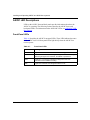
AN/DC LED Descriptions ................................................................................................4-4
Front-Panel LEDs .....................................................................................................4-4
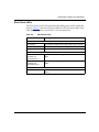
Back-Panel LEDs .....................................................................................................4-5
ANH-8/DC LED Descriptions ..........................................................................................4-6
Front-Panel LEDs .....................................................................................................4-6
Back-Panel LEDs .....................................................................................................4-7
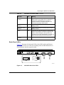
Powering On and Off ......................................................................................................4-8
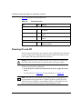
Resetting the AN/DC or ANH-8/DC ..............................................................................4-10
AN/DC Reset Switch ..............................................................................................4-11
ANH-8/DC Reset Switch ........................................................................................4-11
Removing a Flash Memory Card ..................................................................................4-12
Protecting Memory Card Files ......................................................................................4-13
Appendix A
Configuring Netboot and Directed Netboot
Using the ifconfig Command ......................................................................................... A-1
Configuring a Synchronous IP Interface for Netbooting .......................................... A-2
Configuring an Ethernet Interface for Netbooting .................................................... A-3
Enabling and Disabling Interfaces with ifconfig .............................................................. A-4
Using the bconfig Command ......................................................................................... A-4
312410-A Rev 00
xi
Appendix B
Using Local Boot (the Quick-Start Procedure)
Filling Out the Quick-Start Worksheets ......................................................................... B-2
Global Information Worksheet ................................................................................. B-3
Router Protocol Worksheets ................................................................................... B-5
Wide Area Protocol Worksheets ............................................................................. B-9
Using the Quick-Start Commands ............................................................................... B-12
Running the Quick-Start Script .................................................................................... B-13
Appendix C
Technical Specifications
AN/DC Physical Specifications ...................................................................................... C-1
ANH-8/DC Physical Specifications ................................................................................ C-1
Power Supply Specifications .......................................................................................... C-2
AN/DC Hardware Communications Options .................................................................. C-2
ANH-8/DC Hardware Communications Options ............................................................ C-4
Connector Pinouts ......................................................................................................... C-5
Attachment Unit Interface (AUI) Ports ..................................................................... C-6
10Base-T Repeater Ports (ANH-8/DC only) ........................................................... C-7
Synchronous Interfaces .......................................................................................... C-8
ISDN BRI Ports ..................................................................................................... C-10
Local Console Connections .................................................................................. C-10
Appendix D
Requirements for European Operation
ANH-8/DC Safety Status ............................................................................................... D-1
AN/DC Safety Status ..................................................................................................... D-2
Safety Status (Third Synchronous Interface Module) .................................................... D-2
Synchronous Cabling Requirements ............................................................................. D-3
ISDN BRI Requirements ................................................................................................ D-7
Power Requirements ............................................................................................... D-7
ISDN BRI Clearances and Creepage Distances ..................................................... D-8
ISDN BRI Upgrade Module Safety Status ............................................................... D-9
ISDN BRI Connector Pinouts ................................................................................ D-10
Index
xii
312410-A Rev 00
Figures
Figure 1-1.
Mounting Hardware ..................................................................................1-2
Figure 1-2.
Console Cables ........................................................................................1-3
Figure 1-3.
Attaching Flange Brackets to the AN/DC .................................................1-7
Figure 1-4.
Installing the AN/DC in a Rack .................................................................1-8
Figure 1-5.
Mounting the AN/DC on a Wall ..............................................................1-10
Figure 1-6.
Plugging Cables into the AN/DC ............................................................1-11
Figure 1-7.
Attaching the Modem Adapter to the Console Cable .............................1-13
Figure 1-8.
Connecting a Terminal Console .............................................................1-14
Figure 1-9.
Connecting a PC Console ......................................................................1-15
Figure 1-10. Connecting a Modem .............................................................................1-17
Figure 1-11. AN/DC Power Switch and DC Terminals ................................................1-18
Figure 1-12. Attaching AN/DC Power Input Cables ....................................................1-19
Figure 1-13. Attaching AN/DC Power and Ground Cables .........................................1-20
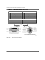
Figure 2-1.
Accessories in the ANH-8/DC Shipping Container ..................................2-3
Figure 2-2.
Sample Cagenuts and Screws for Unthreaded Rack Rails ......................2-4
Figure 2-3.
Attaching Flange Brackets to Rack-Mount the ANH-8/DC .......................2-8
Figure 2-4.
Installing the ANH-8/DC in an Electronic Enclosure Rack .......................2-9
Figure 2-5.
Attaching Flange Brackets to Wall-Mount the ANH-8/DC ......................2-10
Figure 2-6.
Mounting the ANH-8/DC on a Wall ........................................................2-11
Figure 2-7.
Connecting an AUI Cable .......................................................................2-12
Figure 2-8.
Connecting Repeater UTP Cables .........................................................2-13
Figure 2-9.
ANH-8/DC Front-Panel MDI-X/MDI Switch ............................................2-14
Figure 2-10. Linking ANH-8/DC Systems ...................................................................2-15
Figure 2-11. Linking Hubs ..........................................................................................2-16
Figure 2-12. Connecting a Second Ethernet Interface Cable .....................................2-17
Figure 2-13. Connecting Synchronous Cables to COM1, COM2, or COM3 ..............2-18
Figure 2-14. Connecting an ISDN BRI Cable .............................................................2-19
Figure 2-15. Attaching the Null Modem Adapter ........................................................2-21
Figure 2-16. Connecting a Terminal Console to the ANH-8/DC .................................2-21
312410-A Rev 00
xiii
Figure 2-17. Connecting a PC Console to the ANH-8/DC ..........................................2-23
Figure 2-18. Connecting a Modem to the ANH-8/DC .................................................2-25
Figure 2-19. ANH-8/DC Power Switch and DC Terminals ..........................................2-26
Figure 2-20. Attaching the ANH-8/DC Power Input Cables ........................................2-27
Figure 2-21. Attaching the ANH-8/DC Earth Ground Cable .......................................2-28
Figure 3-1.
Flash Memory Card .................................................................................3-3
Figure 3-2.
Inserting the Flash Memory Card in the AN/DC Receptacle ...................3-4
Figure 3-3.
Inserting a Flash Memory Card in the ANH-8/DC Card Receptacle ........3-5
Figure 3-4.
Running Diagnostics ................................................................................3-7
Figure 3-5.
Logging In to the Diagnostic Monitor .......................................................3-8
Figure 3-6.
Sample Interface Configuration Command ..............................................3-9
Figure 3-7.
Verifying the Interface Configuration ......................................................3-10
Figure 3-8.
Netboot ..................................................................................................3-11
Figure 3-9.
Specifying the Source for Directed Netboot ...........................................3-12
Figure 3-10. Verifying Directed Netboot Configuration ...............................................3-13
Figure 3-11. Directed Netboot ....................................................................................3-14
Figure 3-12. Local Boot ..............................................................................................3-16
Figure 3-13. Logging In to the Technician Interface and Mounting a Volume .............3-17
Figure 4-1.
AN/DC Front-Panel LEDs ........................................................................4-2
Figure 4-2.
ANH-8/DC Front-Panel LEDs ...................................................................4-2
Figure 4-3.
ANH-8/DC Back-Panel LEDs ...................................................................4-7
Figure 4-4.
AN/DC Power Switch ...............................................................................4-9
Figure 4-5.
ANH-8/DC Power Switch .........................................................................4-9
Figure 4-6.
AN/DC Reset Button ..............................................................................4-11
Figure 4-7.
ANH-8/DC Reset Button ........................................................................4-11
Figure 4-8.
AN/DC Flash Memory Card Eject Button ...............................................4-12
Figure 4-9.
ANH-8/DC Flash Memory Card Eject Button .........................................4-12
Figure 4-10. Memory Card Read-Write Protect Switch ..............................................4-13
xiv
Figure D-1.
Cable 7837 (V.28 Compliant) .................................................................. D-3
Figure D-2.
Cable 7220 (V.35 Compliant) .................................................................. D-4
Figure D-3.
Cable 7224 (X.21 Compliant) .................................................................. D-6
Figure D-4.
ISDN BRI Clearances and Creepage Distances ..................................... D-8
312410-A Rev 00
Tables
Table 1-1.
Console Parameters ..............................................................................1-13
Table 1-2.
Modem Parameters ................................................................................1-16
Table 2-1.
Console Parameters ..............................................................................2-20
Table 2-2.
Modem Parameters ................................................................................2-24
Table 3-1.
Summary of Initial Startup Options ..........................................................3-2
Table 4-1.
Front-Panel LEDs .....................................................................................4-4
Table 4-2.
Back-Panel LEDs ....................................................................................4-5
Table 4-3.
ANH-8/DC Front-Panel LEDs ...................................................................4-6
Table 4-4.
Back-Panel LEDs .....................................................................................4-8
Table A-1.
The ifconfig Command Settings for a Synchronous Interface ................. A-2
Table A-2.
The ifconfig Command Settings for an Ethernet Interface ...................... A-3
Table A-3.
The bconfig Command Options .............................................................. A-5
Table B-1.
Quick-Start Commands ........................................................................ B-12
Table C-1.
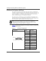
AN/DC Network Interfaces ...................................................................... C-3
Table C-2.
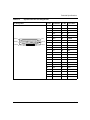
ANH-8/DC Network Interfaces ................................................................ C-5
Table C-3.
AUI Port Pin Assignments ....................................................................... C-6
Table C-4.
RJ-45 Jacks Pin Assignments ................................................................. C-7
Table C-5.
Synchronous Port Pin Assignments ........................................................ C-9
Table C-6.
ISDN Connector Pinouts ....................................................................... C-10
Table C-7.
Service (Console) Port DB-9 Pin Assignments ..................................... C-11
Table D-1.
Safety Status (Order Nos. AE1001041, AE1001042, AE1001043, and
AE1001044) ............................................................................................ D-1
Table D-2.
Safety Status (Order Nos. AE0004005, AE0011012, and
AE0011020)
D-1
Table D-3.
Safety Status (Order Nos. AE0004006, AE0011013, and
AEE0011019) .......................................................................................... D-2
Table D-4.
Safety Status (Order Nos. AE1001037, AE1001038, AE1001039, and
AE1001040) ............................................................................................ D-2
Table D-5.
Safety Status (Order Nos. 24001, 50025, and 24001-S) ........................ D-2
Table D-6.
WAN Interface (Order No. 7837) ............................................................. D-3
312410-A Rev 00
xv
xvi
Table D-7.
V.35 Interface (Order No. 7220) .............................................................. D-5
Table D-8.
X.21 Interface (Order No. 7224) .............................................................. D-6
Table D-9.
ISDN BRI Power Requirements .............................................................. D-7
Table D-10.
ISDN BRI Clearances and Creepage Distances ..................................... D-9
Table D-11.
ISDN BRI Safety Status (Order Nos. 24000, 24000-S, 50022,
AE0004006, AE0011013, and AE0011019) ............................................ D-9
Table D-12.
ISDN Connector Pinouts ....................................................................... D-10
312410-A Rev 00
Preface
Read this guide for instructions on how to install, start, and operate Access Node
or 8-Port Access Node Hub models that have a single DC input switching power
supply, the AN™/DC and ANH™-8/DC. This guide describes
•
Physically installing the AN/DC (Chapter 1) or the ANH-8/DC (Chapter 2)
and attaching communications equipment
•
Connecting the AN/DC or ANH-8/DC to the network using one of the Site
Manager software configuration options (Chapter 3)
•
Using the AN/DC or ANH-8/DC operator switches and interpret LED
displays (Chapter 4)
Before You Begin
Before using this guide, you must complete the following procedures. For a new
router:
•
Install the router (see the installation guide that came with your router).
•
Connect the router to the network and create a pilot configuration file (see
Quick-Starting Routers, Configuring Remote Access for AN and Passport
ARN Routers, or Connecting ASN Routers to a Network).
Make sure that you are running the latest version of Nortel Networks BayRS™ and
Site Manager software. For information about upgrading BayRS and Site
Manager, see the upgrading guide for your version of BayRS.
312410-A Rev 00
xvii
Installing and Operating AN/DC and ANH-8/DC Systems
Text Conventions
This guide uses the following text conventions:
angle brackets (< >)
Indicate that you choose the text to enter based on the
description inside the brackets. Do not type the
brackets when entering the command.
Example: If the command syntax is:
ping <ip_address>, you enter:
ping 192.32.10.12
bold text
Indicates command names and options and text that
you need to enter.
Example: Enter show ip {alerts | routes}.
Example: Use the dinfo command.
brackets ([ ])
Indicate optional elements in syntax descriptions. Do
not type the brackets when entering the command.
Example: If the command syntax is:
show ip interfaces [-alerts], you can enter either:
show ip interfaces or show ip interfaces -alerts.
italic text
Indicates file and directory names, new terms, book
titles, and variables in command syntax descriptions.
Where a variable is two or more words, the words are
connected by an underscore.
Example: If the command syntax is:
show at <valid_route>
valid_route is one variable and you substitute one value
for it.
xviii
312410-A Rev 00
Preface
screen text
Indicates system output, for example, prompts and
system messages.
Example: Set Trap Monitor Filters
vertical line ( | )
Separates choices for command keywords and
arguments. Enter only one of the choices. Do not type
the vertical line when entering the command.
Example: If the command syntax is:
show ip {alerts | routes}, you enter either:
show ip alerts or show ip routes, but not both.
Acronyms
This guide uses the following acronyms:
312410-A Rev 00
AN/DC
Access Node (AN) with DC power supply
ANH-8/DC
8-Port Access Node Hub (ANH) with DC power supply
ANSI
American National Standards Institute
AUI
Attachment Unit Interface
BootP
Bootstrap Protocol
BRI
Basic Rate Interface
CCITT
(now ITU-T)
CSMA/CD
carrier sense multiple access with collision detection
CTS
clear to send
DCD
data carrier detect
DCE
data communications equipment
DCM
RMON Data Collection Module
DLCMI
Data Link Control Management Interface
DSR
data set ready
DTE
data terminal equipment
DTR
data terminal ready
EIA
Electronic Industries Association
GUI
graphical user interface
HDLC
high-level data link control
xix
Installing and Operating AN/DC and ANH-8/DC Systems
xx
IEEE
Institute of Electrical and Electronic Engineers
IP
Internet Protocol
ISDN
Integrated Services Digital Network
ISO
International Organization for Standardization
ITU-T
International Telecommunication Union –Telecommunication (formerly CCITT)
LAN
local area network
LED
light-emitting diode
LMI
Local Management Interface
MAC
media access control
MAU
media access unit
MDI
Medium-Dependent Interface
MDI-X
Medium-Dependent Interface with Crossover
NBMA
non broadcast multi-access
NEMA
National Electrical Manufacturers Association
NVFS
Nonvolatile File System
OSI
Open Systems Interconnection
OSPF
Open Shortest Path First Protocol
PCMCIA
Personal Computer Memory Card International Association
PPP
Point-to-Point Protocol
RIP
Routing Information Protocol
RLSD
received line signal detection
RTS
request to send
SMDS
switched multimegabit data service
SNMP
Simple Network Management Protocol
STP
shielded twisted-pair
TCP/IP
Transmission Control Protocol/Internet Protocol
TELNET
Telecommunication Network
TFTP
Trivial File Transfer Protocol
TPE
twisted-pair Ethernet
UTP
unshielded twisted-pair
WAN
wide area network
312410-A Rev 00
Preface
Hard-Copy Technical Manuals
You can print selected technical manuals and release notes free, directly from the
Internet. Go to the support.baynetworks.com/library/tpubs/ URL. Find the product
for which you need documentation. Then locate the specific category and model
or version for your hardware or software product. Use Adobe Acrobat Reader to
open the manuals and release notes, search for the sections you need, and print
them on most standard printers. Go to Adobe Systems at www.adobe.com to
download a free copy of Acrobat Reader.
You can purchase selected documentation sets, CDs, and technical publications
through the Internet at the www1.fatbrain.com/documentation/nortel/ URL.
How to Get Help
If you purchased a service contract for your Nortel Networks product from a
distributor or authorized reseller, contact the technical support staff for that
distributor or reseller for assistance.
If you purchased a Nortel Networks service program, contact one of the following
Nortel Networks Technical Solutions Centers:
Technical Solutions Center
Telephone
EMEA
(33) (4) 92-966-968
North America
(800) 2LANWAN or (800) 252-6926
Asia Pacific
(61) (2) 9927-8800
China
(800) 810-5000
An Express Routing Code (ERC) is available for many Nortel Networks products
and services. When you use an ERC, your call is routed to a technical support
person who specializes in supporting that product or service. To locate an ERC for
your product or service, go to the www12.nortelnetworks.com/ URL and click
ERC at the bottom of the page.
312410-A Rev 00
xxi
Chapter 1
Installing the AN/DC
This chapter describes how to install the AN/DC.
Danger: Due to high-energy hazards, only qualified service personnel are
permitted to install the AN/DC.
Topics in this chapter include
•
•
•
•
•
Preparing for Installation
Installing the AN/DC (on a desktop, in a rack, or on the wall)
Connecting Communications Cables
Connecting a Management Console or Modem
Connecting to the DC Power Source
For information on how to install the ANH-8/DC, go to Chapter 2. For technical
specifications and an overview of the AN/DC hardware, refer to Appendix C.
Preparing for Installation
To prepare for installation, complete the steps in the next sections to verify that:
•
•
The AN/DC shipment is complete and undamaged.
You have the proper tools and equipment.
•
The installation location meets all site requirements.
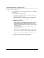
Verifying Shipment Contents
Verify that the items you receive match the items in the packing list attached to the
shipping container.
312410-A Rev 00
1-1
Installing and Operating AN/DC and ANH-8/DC Systems
1.
Inspect all items for any shipping damage.
Caution: In particular, check the AN/DC for any damage to the ports on the
back panel. If you detect damage, do not install the AN/DC. Call your local
Nortel Networks Technical Response Center.
2.
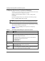
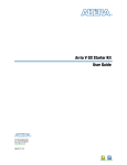
Make sure that your shipping package contains the following items:
•
•
•
•
•
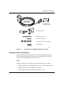
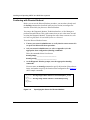
Mounting hardware (Figure 1-1).
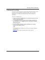
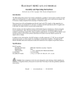
Console/modem cable kit (Figure 1-2).
Any network cables ordered with the router. If you do not have the
appropriate network cables, contact your network administrator.
Warranty information.
This guide.
Four rubber feet
Two flange backets
(for installing the AN in an
equipment rack or
mounting it on a wall)
Four cagenuts with screws
(for installing the AN in an
equipment rack)
2 wall anchors
(for mounting the AN on a wall)
AN0001A
Figure 1-1.
1-2
Mounting Hardware
312410-A Rev 00
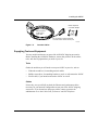
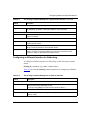
Installing the AN/DC
DB-25 receptacle
null nodem adapter
DB-9 receptacle
to DB-25 plug
serial cable
For connecting an optional terminal
or modem to the console service port
AN0002A
Figure 1-2.
Console Cables
Supplying Tools and Equipment
You may need items that are not part of the ANH-8/DC shipping accessories.
Before installing the ANH-8/DC hardware, ensure that you have all the cables,
tools, and other equipment that you need at your site.
Tools
Gather the tools that you will need to set up an AN/DC at your site, such as:
•
Flathead screwdriver, for attaching network cables
•
Phillips screwdriver, for attaching brackets to rack- or wall-mount the AN/DC
•
Electric drill, if you intend to mount the AN/DC on a wall
Cables
Unless they were specifically ordered, the Ethernet and synchronous cables
necessary for your network configuration are not part of the AN/DC shipping
accessories. If you do not have the proper cables, contact your network
administrator or see the Cable Guide for Routers and BNX Platforms.
312410-A Rev 00
1-3
Installing and Operating AN/DC and ANH-8/DC Systems
Service Console
You can attach an optional VT-100 console or equivalent to the AN/DC to monitor
the results of startup diagnostics and perform manual boot configurations; or you
can attach any AT-compatible modem to allow remote dial-in access to diagnostics
and configuration.
Note: To use the Netboot, Directed Netboot, or Local Boot configuration
options (see Chapter 3), there must be a local terminal connected the first time
that the ANH-8/DC powers up.
Mounting Hardware
To rack-mount the AN/DC, you need an electronic enclosure rack that meets the
following specifications:
•
Heavy-duty steel construction
•
Electronic Industries Association (EIA) standard hole-spacing
•
Width of 19 in. (48.26 cm) and depth of 24 in. (60.96 cm)
If the rack’s rails do not have threaded holes, you must supply cagenuts to use
with the cagenut screws (see Figure 1-4).
Verifying Site Requirements
Verify that your installation meet the requirements listed in this section.
•
Space Requirements
•
Electrical Requirements
•
Environmental Requirements
Note: The AN/DC should be installed only in dedicated equipment rooms
where access is limited to qualified service personnel.
1-4
312410-A Rev 00
Installing the AN/DC
Space Requirements
The installation site must provide a certain amount of free space around the
AN/DC to dissipate heat. Install the AN/DC in a space that meets the following
specifications:
•
•
•
Width: 19.5 in. (49.6 cm)
Minimum depth: 15.5 in. (39.3 cm)
Depth for servicing: 24.5 in. (62.2 cm)
Electrical Requirements
The installation site must provide an isolated power source that meets these
electrical specifications:
•
Input voltage of -48.0 or -60.0 volts DC, +/- 20%
•
1.5 amperes (A) input current under full load at -38.0 VDC input
•
Reinforced insulation from the main AC power
We recommend the use of #16 AWG cables between the AN/DC and the power
source to minimize voltage drop. When measuring the cable run, be certain to
include both the input and return cables.
Environmental Requirements
The AN/DC installation site must meet the following specifications:
312410-A Rev 00
•
•
Altitude: 0 to 8,000 ft (0 to 2,438.4 m)
Humidity: 10% to 90%, noncondensing
•
Temperature: 32°F to 104°F (0°C to 40°C) stable
1-5
Installing and Operating AN/DC and ANH-8/DC Systems
Installing the AN/DC
With all cabling attached, you can install the AN/DC in any of the following ways:
•
Position the AN/DC on a flat, sturdy surface.
•
Install the AN/DC in an electronic enclosure rack.
•
Mount the AN/DC on a wall.
The following sections provide instructions for each option. Refer to the
appropriate section when positioning your AN/DC.
Positioning the AN/DC on a Flat Surface
To position the AN/DC on a flat surface:
1.
Make sure that the surface is large enough for the AN/DC to operate
properly.
The surface must be sturdy enough to support the combined weight of the
AN/DC and any cables you connect.
2.
Peel the paper backing off the four rubber feet supplied with the AN/DC
and attach them to the embossed feet on the bottom of the AN/DC.
3.
Set the AN/DC in the chosen location.
You can now connect the network cables to the AN/DC. Go to the section
“Connecting Communications Cables,” later in this chapter.
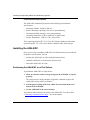
Installing the AN/DC in a Rack
For this procedure, you need
•
Mounting hardware that came with the AN/DC shipment
•
An electronic enclosure rack
•
Phillips screwdriver
Note: If the rack’s rail does not have threaded holes, you must supply and
attach four cagenuts.
1-6
312410-A Rev 00
Installing the AN/DC
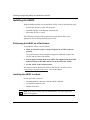
To install the AN/DC in a rack:
1.
Attach each flange bracket to the AN/DC (Figure 1-3) as follows:
a.
Align the flange holes with the AN/DC mounting holes.
b.
Insert a flange screw through each flange hole and into the AN/DC.
c.
Tighten each flange screw with a Phillips screwdriver.
Power
Run
Boot
Diag
Screws
(4 places)
AN0003A
Figure 1-3.
Attaching Flange Brackets to the AN/DC
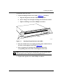
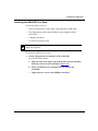
2.
Place the AN/DC in the rack, aligning the flange holes with the holes in
the front vertical supports of the rack (Figure 1-4).
3.
Insert a cagenut screw through each flange hole and into the
corresponding holes in the front vertical supports of the rack.
Note: If the rack’s rail does not have threaded holes, use the cagenuts along
with the cagenut screws. Otherwise, just use the cagenut screws.
4.
312410-A Rev 00
Tighten each cagenut screw with a Phillips screwdriver.
1-7
Installing and Operating AN/DC and ANH-8/DC Systems
RUN
BOOT
POWER
DIAG
Cagenut screw
(4 places)
Rail without
threaded holes
Use cagenut
AN0004A
Figure 1-4.
Installing the AN/DC in a Rack
You can now connect the network cables to your AN/DC. Go to the section
“Connecting Communications Cables,” later in this chapter.
1-8
312410-A Rev 00
Installing the AN/DC
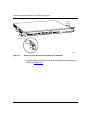
Mounting the AN/DC on a Wall
When mounting the AN/DC on a wall, keep the following in mind:
•
Make sure that the wall is at least 3/8 in. (0.96 cm) thick, and is made of
Sheetrock or wood.
•
You need the following equipment before you start:
-- An electric drill
-- A Phillips screwdriver
-- Two wall-mount anchors
To mount the AN/DC on the wall:
312410-A Rev 00
1.
Drill two 5/16-in. (0.8 cm) holes in the wall 5-1/4 in. (13.34 cm) apart, at
least 3 ft. (0.915 m) off the floor.
2.
Insert one wall-mount anchor into each hole.
3.
Tighten the anchors with a Phillips screwdriver.
4.
Back the head of each screw out 1/8 in. (0.32 cm) from the wall.
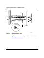
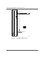
5.
Hang the AN/DC on the wall by aligning the keyhole cutouts on the back
of the AN/DC with the protruding screw heads (Figure 1-5).
1-9
POWER
RUN
BOOT
DIAG
Installing and Operating AN/DC and ANH-8/DC Systems
Rubber feet
AN0005A
Figure 1-5.
1-10
Mounting the AN/DC on a Wall
312410-A Rev 00
Installing the AN/DC
Connecting Communications Cables
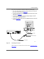
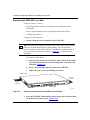
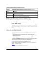
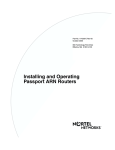
To connect network cables to the back of the AN/DC:
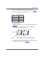
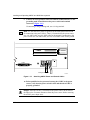
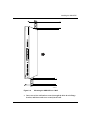
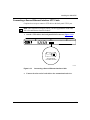
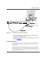
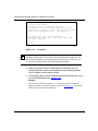
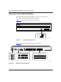
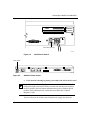
1.
Connect the appropriate cables for your network configuration to the
communications ports on the back of the AN/DC (Figure 1-6).
For some cables, you may need a flathead screwdriver to secure the connector
in place. Figure 1-6 illustrates a sample cable configuration. Appendix C
describes and provides more detail on the communications ports available on
the different AN/DC models.
P/N
1¯7913-24
S/N
ATX15¯8
MODEL
ACCESS NODE (AN) TM
COMMUNICATIONS SERVER
MADE
IN
UL
S403
LISTED EDP
EQUIPMENT
U.S.A.
This equipment complies with the requirements in part 15 of FCC rules for Class A computing device
Operation of the equipment in a residential area may cause unacceptable interference to radio and TV
reception requiring the operator to take whatever steps are nessessary to correct the interference.
UL
L6 4490313
22¯¯2
-48VDC
XCVR
Ethernet
Transceiver
UTP
TX
RX
CL
COM 2
CONSOLE
-60VDC
COM 1
1.5A
RST
RLSD2
RLSD1
RTN
-VDC
Modem,
Console
or PC Cable
ThinNet Cable
Synchronous
Cables
AN0089B
Figure 1-6.
Plugging Cables into the AN/DC
2.
Connect the network cables to the physical network.
Contact your network administrator or see the Cable Guide for Routers and BNX
Platforms if you need assistance in connecting the AN/DC to the physical network
devices, or if you are missing any network cables.
312410-A Rev 00
1-11
Installing and Operating AN/DC and ANH-8/DC Systems
Connecting a Management Console or Modem
Use the front-panel console port to connect an ASCII-based terminal, a personal
computer terminal emulator, or a modem to the AN/DC. Using a local terminal,
you can monitor the results of startup diagnostics and set the boot configuration.
Using an attached modem, you can allow remote dial-in access to diagnostics.
To determine whether you need to connect a console to the AN/DC, contact your
network administrator to find out which software configuration option (EZ Install,
Netboot, Directed Netboot, or Local Boot) is best for your site.
Refer to Chapter 2 for information on the software configuration options. You
must connect a console to the AN/DC to use Netboot, Directed Netboot, or Local
Boot.
Although you do not need a console or modem connection for EZ Install, we
strongly recommend that you connect a console or modem to the AN/DC. This
lets you issue commands to the AN/DC and view messages.
Note: To use the Netboot, Directed Netboot, or Local Boot software
configuration options, you must connect a console the first time you power up
the AN/DC, as described in Chapter 3.
Complete the steps in one of the following sections:
•
Connecting a Terminal Console
•
Connecting a PC Console
•
Connecting a Modem
Connecting a Terminal Console
To connect a console, you need both pieces in the AN/DC console/modem cable
kit (Order No. 110310) that shipped with the router (refer to Figure 1-2):
1-12
•
Order No. 110307 serial console/modem cable (with 9-pin receptacle to
25-pin plug connectors)
•
Order No. 110308 null modem crossover adapter (with two 25-pin receptacle
connectors)
312410-A Rev 00
Installing the AN/DC
Once you have the appropriate equipment, complete the following steps:
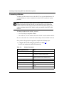
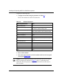
1.
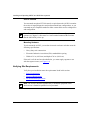
Power on and configure the console, using the parameters in Table 1-1.
Refer to the console user manual for instructions.
Table 1-1.
Console Parameters
Parameter
Value
Baud Rate
9600
Data Bits
8
Stop Bits
1
Parity
None
2.
Power off the console.
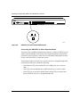
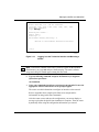
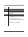
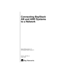
3.
Attach the null modem crossover adapter to the 25-pin cable connector
(Figure 1-7).
4.
Insert the screws on the cable connector into the receptacle on the
adapter connector and tighten each screw.
Console cable connector
Rotate to tighten screw
Null modem crossover adapter
Screw receptacle
AN0010A
Figure 1-7.
5.
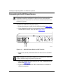
312410-A Rev 00
Attaching the Modem Adapter to the Console Cable
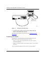
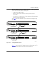
Insert the 9-pin receptacle end of the console cable into the CONSOLE
port on the back panel of the AN/DC (Figure 1-8).
1-13
Installing and Operating AN/DC and ANH-8/DC Systems
COMM
20 mA
PR
KB
UL
UL
-48VDC
-60VDC
1.5A
XCVR
UTP
TX
RX
CL
COM 2
CONSOLE
COM 1
RST
RSLD2
RSLD1
RTN
-VDC
Console Cable Plus
Null Modem Adapter
AN0011B
Figure 1-8.
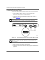
6.
Connecting a Terminal Console
Attach the 25-pin receptacle connector on the combined cable and
adapter to the terminal’s host connector.
The console is now connected. Proceed to the section “Connecting to the DC
Power Source.”
Connecting a PC Console
To connect a PC, you need both pieces in the console/modem cable kit that
shipped with the router (Nortel Networks Order No. 110310):
•
Order No. 110307 serial console/modem cable (with 9-pin receptacle to
25-pin plug connectors)
•
Order No. 110308 null modem crossover adapter (with two 25-pin receptacle
connectors)
You also need another standard serial cable with a 25-pin plug connector.
1-14
312410-A Rev 00
Installing the AN/DC
Once you have the appropriate equipment, complete the following steps:
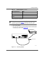
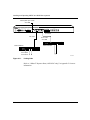
1.
Insert the 9-pin receptacle end of the console cable into the CONSOLE
port on the AN/DC back panel (Figure 1-9).
2.
Attach the null modem crossover adapter to the other end of the console
cable (refer to Figure 1-7).
3.
Attach the 25-pin receptacle end of the cable-plus-adapter to the PC
console cable’s 25-pin plug connector.
4.
Connect the complete cable unit to the communications port at the back
of the PC (Figure 1-9).
UL
UL
-48VDC
-60VDC
1.5A
XCVR
UTP
CONSOLE
TX
RX
CL
COM 2
COM 1
RST
RSLD2
RSLD1
RTN
PC Cable
-VDC
Null Modem Adapter
Console Cable
AN0012A
Figure 1-9.
Connecting a PC Console
The PC console is now connected. Proceed to the section “Connecting to the DC
Power Source.”
312410-A Rev 00
1-15
Installing and Operating AN/DC and ANH-8/DC Systems
Connecting a Modem
A modem provides remote access to the AN/DC for a network administrator. We
recommend that you connect a modem in case the AN/DC experiences system
problems.
Note: Netboot, Directed Netboot, and Local Boot require a terminal or PC
console connection. After the AN/DC is on the network, you can replace the
console connection with a modem connection. When using EZ Install, you can
connect a modem to the AN/DC before or after you connect the AN/DC to the
network.
To connect a modem to the AN/DC, you need
•
An AT (or Hayes) compatible modem
•
The Order No. 110307 modem cable in the AN/DC console/modem cable kit
Do not use the Order No. 110308 null modem adapter from the AN/DC cable kit.
Once you have the appropriate equipment, complete the following steps:
1.
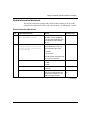
Configure the modem, using the parameters in Table 1-2.
Refer to the modem user manual for instructions.
Table 1-2.
Modem Parameters
Modem Signal/Parameter
Value
Clear To Send (CTS)
On
Data Terminal Ready (DTR)
Depends on the modem type. Set DTR to require
the modem to answer incoming calls.
Data Carrier Detect (DCD) *
On while carrier is present (the AN/DC uses DCD
to detect modem connect and disconnect).
Data Set Ready (DSR)
On
Ready to Send (RTS)
Ignore
Synchronous/Asynchronous Mode
Asynchronous
AutoAnswer
Set on n rings with DTR active (n must be greater
than 0).
Local Character Echo
Off
(continued)
1-16
312410-A Rev 00
Installing the AN/DC
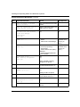
Table 1-2.
Modem Parameters (continued)
Modem Signal/Parameter
Value
Supervisory Functions
Off
Baud Rate
9600 (or less)
Data Bits
8
Stop Bits
1
Parity
None
* The DCD signal is also called RLSD.
Caution: Do not connect a modem to the AN/DC until you are certain that it
is configured as described in Table 1-2. Connecting to the AN/DC with an
improperly configured modem could cause the router to fail or lose data.
2.
Power off the modem.
3.
Insert the 9-pin receptacle end of the modem cable into the back-panel
CONSOLE port of the AN/DC (Figure 1-10).
PHONE
DWR
(LEASE
3810
DIAL
NMS
DTE
(LEASED)
3810
UL
UL
-48VDC
-60VDC
1.5A
XCVR
UTP
TX
RX
CL
COM 2
CONSOLE
COM 1
RST
RSLD2
RSLD1
RTN
-VDC
Modem Cable
AN0013A
Figure 1-10.
312410-A Rev 00
Connecting a Modem
1-17
Installing and Operating AN/DC and ANH-8/DC Systems
4.
Insert the 25-pin plug at the other end of the modem cable into the
modem’s RS-232 data communications port.
The modem is now connected to the AN/DC.
Next, connect the power source as described in the following section.
Connecting to the DC Power Source
Danger: Due to high-energy hazards, only qualified service personnel are
permitted to connect the AN/DC to the power source.
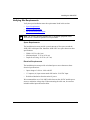
To connect the AN/DC to the power source:
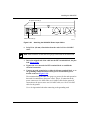
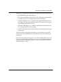
1.
Ensure that the power switch is in the OFF (0) position (Figure 1-11).
2.
Using a flathead screwdriver, loosen, but do not remove, the screws
beneath the terminal blocks marked -VDC and RTN (Figure 1-11).
UL
UL
DC Power Terminals (3)
-48VDC
-60VDC
1.5A
COM 1
RTN
-VDC
Power Switch OFF (0)
AN0093A
Figure 1-11.
1-18
AN/DC Power Switch and DC Terminals
312410-A Rev 00
Installing the AN/DC
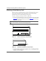
3.
Strip 3/8 in. (10 mm) of insulation from the end of a #16 or #18 AWG
cable.
Note: Although #18 AWG cable is adequate, we recommend #16 AWG cable
to ensure minimal voltage drop from the power source.
4.
Insert the stripped end of the cable into the -VDC terminal block, the
minus lead (Figure 1-12).
5.
Tighten the screw beneath the -VDC terminal block to establish the
electrical connection.
UL
UL
Power Switch OFF (0)
-48VDC
-60VDC
COM 1
1.5A
RTN
-VDC
AN0091B
Figure 1-12.
6.
Attaching AN/DC Power Input Cables
Strip 3/8 in. (10 mm) of insulation from a #16 or #18 AWG cable.
Make certain to use the same wire gauge as that used for the minus lead.
312410-A Rev 00
7.
Insert the stripped end of the cable into the RTN terminal block, the plus
lead (Figure 1-12).
8.
Tighten the screw beneath the RTN terminal block to establish the
electrical connection.
1-19
Installing and Operating AN/DC and ANH-8/DC Systems
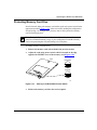
9.
Connect an earth ground to either the leftmost terminal block or to the
grounding stud, located between the power switch and terminal
connectors (Figure 1-13).
If connecting to the grounding stud, use a #6 ring terminal.
Note: Use the same wire gauge (or greater) for the earth ground as that used
for connection to the power source. That is, if connection to the power source
uses #16 AWG cable, use #16 AWG cable for the ground. If connection to the
power source uses #18 AWG cable, use #18 or #16 AWG cable for the ground.
UL
UL
-48VDC
-60VDC
1.5A
COM 1
RTN
-VDC
Earth ground options
AN0092A
Figure 1-13.
Attaching AN/DC Power and Ground Cables
10. Before qualified service personnel connect the AN/DC to the power
source, verify that the power switch is OFF and that the AN/DC is
properly grounded.
Danger: Once the AN/DC is connected to the power source, do not remove
the input wires. You must disconnect from the power source before removing
the AN/DC power input wires.
1-20
312410-A Rev 00
Chapter 2
Installing the ANH-8/DC
This chapter describes how to install the ANH-8/DC.
Danger: Due to high-energy hazards, only qualified service personnel are
permitted to install the ANH-8/DC.
Topics in this chapter include:
•
•
•
•
•
Preparing for Installation
Installing the ANH-8/DC
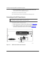
Connecting Communications Cables
Connecting a Management Console or Modem
Connecting to the DC Power Source
For information on how to install the AN/DC, see Chapter 1. For technical
specifications and an overview of the ANH-8/DC hardware, refer to Appendix C.
Preparing for Installation
To prepare for installation, complete the steps in the next sections to verify that:
312410-A Rev 00
•
•
Your shipment is complete and undamaged.
You have the proper equipment and tools.
•
The installation location meets all site requirements.
2-1
Installing and Operating AN/DC and ANH-8/DC Systems
Verifying Shipment Contents
Verify that the items you receive match the items in the packing list attached to the
shipping container.
1.
Inspect all items for shipping damage.
If you detect any damage, do not install the ANH-8/DC. Call the Nortel
Networks Technical Response Center.
2.
Verify that the items you received match the items in the packing list.
The packing list is usually affixed to the shipping container.
3.
Make sure that you received
•
One cable kit (Order No. 110310) for connecting an optional local
console or modem. The console/modem cable kit contains one 15-foot AT
standard molded serial cable (with DB-9 receptacle to DB-25 plug
connectors) and one null modem crossover adapter (with DB-25 to DB-25
receptacle connectors).
•
Two flange brackets with four #10 cagenut screws and washers for
mounting the ANH-8/DC.
•
Eight #6 Class B self-threading flathead screws (for rack-mounting).
•
Four #6 Class B self-threading roundhead screws (for wall-mounting).
•
Four press-on rubber feet (for positioning the ANH-8/DC on a flat
surface).
Figure 2-1 illustrates the ANH-8/DC shipping accessories.
2-2
312410-A Rev 00
Installing the ANH-8/DC
Console/Modem Cable
(DB-9 Receptacle to
DB-25 Plug Cable
DB-25 Receptacle
Null Modem Adapter
Two Flange Brackets
Eight #6 Flathead Screws
Four #6 Roundhead Screws
Four #10 Cagenut Screws and Washers
Four Rubber Feet
AN0037B
Figure 2-1.
Accessories in the ANH-8/DC Shipping Container
Supplying Tools and Equipment
You may need items that are not part of the ANH-8/DC shipping accessories.
Before installing the ANH-8/DC hardware, ensure that you have all the cables,
tools, and other equipment that you need at your site.
Tools
Gather the tools that you will need to set up an AN/DC at your site, such as:
312410-A Rev 00
•
Phillips screwdriver, for attaching brackets to rack- or wall-mount the AN/DC
•
Flathead screwdriver, for attaching network cables
•
Electric drill, if you intend to mount the AN/DC on a wall
2-3
Installing and Operating AN/DC and ANH-8/DC Systems
Cables
Unless they were specifically ordered, the Ethernet and synchronous cables
necessary for your network configuration are not part of the ANH-8/DC shipping
accessories. If you do not have the proper cables, contact your network
administrator or see the Cable Guide for Routers and BNX Platforms.
Service Console
You can attach an optional VT-100 console or equivalent to the ANH-8/DC to
monitor the results of startup diagnostics and perform manual boot configurations;
or you can attach any AT-compatible modem to allow remote dial-in access to
diagnostics and configuration.
Note: To use the Netboot, Directed Netboot, or Local Boot configuration
options (see Chapter 3), there must be a local terminal connected the first time
that the ANH-8/DC powers up.
Mounting Hardware
To rack-mount the ANH-8/DC, you need an electronic enclosure rack that meets
the following specifications:
•
Heavy-duty steel construction
•
Electronic Industries Association (EIA) standard hole-spacing
•
Width of 19 in. (48.26 cm) and depth of 24 in. (60.96 cm)
If the rack’s rails do not have threaded holes, you must supply cagenuts
(Figure 2-2) to use with the cagenut screws.
Screw
Cagenut
AN0038A
Figure 2-2.
Sample Cagenuts and Screws for Unthreaded Rack Rails
To mount the ANH-8/DC on a wall, you need at least four wall-mount anchor
screws (see Figure 2-4).
2-4
312410-A Rev 00
Installing the ANH-8/DC
Verifying Site Requirements
Verify that your installation meet the requirements listed in this section.
•
•
•
Space Requirements
Electrical Requirements
Environmental Requirements
Note: The AN/DC should be installed only in dedicated equipment rooms
where access is limited to qualified service personnel.
Space Requirements
The installation site must provide a certain amount of free space around the
ANH-8/DC to dissipate heat. Install the ANH-8/DC in a space that meets these
specifications:
•
•
•
Width: 19.25 in. (48.9 cm)
Minimum depth: 17.25 in. (43.8 cm)
Depth for servicing: 26.25 in. (66.7 cm)
Electrical Requirements
The installation site must provide an isolated power source that meets these
electrical specifications:
•
Input voltage of -48.0 or -60.0 volts DC
•
1.5 amperes (A) input current under full load at -38.0 VDC input
•
Reinforced insulation from the main AC power
We recommend the use of #16 AWG cables between the AN/DC and the power
source to minimize voltage drop. When measuring the cable run, be certain to
include both the input and return cables.
312410-A Rev 00
2-5
Installing and Operating AN/DC and ANH-8/DC Systems
Environmental Requirements
The ANH-8/DC installation site must meet the following environmental
specifications:
•
•
•
•
•
Maximum Altitude: 10,000 ft (3000 m)
Relative Humidity (Operating): 5% to 85%, noncondensing
Maximum Humidity (Storage): 95%, noncondensing
Operating Temperature: 41°F to 104°F (5°C to 40°C) stable
Storage Temperature: -58°F to 113°F (-50° to 45°C)
These requirements meet IEC 721-3 Class 3K3 climatic conditions while under
operation and IEC 721-3 Class 1K3 climatic conditions while under storage.
Installing the ANH-8/DC
Once you are ready to install the ANH-8/DC in its final location, proceed with one
of the three sections below. You can
•
Position the ANH-8/DC on a flat, sturdy, horizontal surface.
•
Install the ANH-8/DC in an electronic enclosure rack.
•
Mount the ANH-8/DC on a wall.
Positioning the ANH-8/DC on a Flat Surface
To position the ANH-8/DC on a flat surface:
1.
Make sure that the surface is large enough for the ANH-8/DC to operate
properly.
The surface must be sturdy enough to support the combined weight of the
ANH-8/DC and any cables you connect.
2.
Peel the paper backing off the four rubber feet and attach them to the
bottom of the ANH-8/DC.
3.
Set the ANH-8/DC in the chosen location.
You can now connect the network cables to the ANH-8/DC. Go to the section
“Connecting Communications Cables,” later in this chapter.
2-6
312410-A Rev 00
Installing the ANH-8/DC
Installing the ANH-8/DC in a Rack
For this procedure, you need
•
Four #10 cagenut screws and washers (shipped with the ANH-8/DC)
•
Two flange brackets and eight #6 flathead screws (shipped with the
ANH-8/DC)
•
A Phillips screwdriver
•
An electronic enclosure rack
Note: If the rack’s rail does not have threaded holes, you must supply and
attach four cagenuts.
To install the ANH-8/DC in a rack:
1.
Attach a flange bracket to both sides of the ANH-8/DC.
On each side of the chassis:
312410-A Rev 00
a.
Align the holes in the longer end of the bracket with the mounting
holes near the front of the ANH-8/DC (Figure 2-3).
b.
Insert a #6 flathead screw through each hole and into the
ANH-8/DC.
c.
Tighten the four screws with a Phillips screwdriver.
2-7
Installing and Operating AN/DC and ANH-8/DC Systems
Screws
(4 places)
1
2
3
5
4
6
7
Partition
8
1
2
3
5
4
6
7
8
Link
Console
Boot
Run
DCM AUI Part
DCD1 DCD2
MDI-X/MDI
MDI-X
Power
Fault Reset
AUI
<LAN> Col
Screws
(4 places)
AN0040A
Figure 2-3.
Attaching Flange Brackets to Rack-Mount the ANH-8/DC
2.
2-8
Align the flange bracket holes with the holes in the front vertical supports
of the rack (Figure 2-4).
312410-A Rev 00
Installing the ANH-8/DC
1
MDI-X/MDI
2
3
4
5
6
7
8
1
MDI-X
Partition
2
3
4
5
6
MDI-X
7
Access Nod
e Hub
8
Link
Screws
(4 places)
Rail
Cagenut
If the rack rail is not threaded,
attach a cagenut (not supplied).
AN0041A
Figure 2-4.
312410-A Rev 00
Installing the ANH-8/DC in an Electronic Enclosure Rack
3.
Insert a cagenut screw through each bracket hole and into the
corresponding holes in the rack.
4.
Tighten each cagenut screw with a Phillips screwdriver.
2-9
Installing and Operating AN/DC and ANH-8/DC Systems
Mounting the ANH-8/DC on a Wall
For this procedure, you need
•
Two flange brackets and four #6 roundhead screws (shipped with the
ANH-8/DC)
•
Four to eight wall anchor screws (not shipped with the ANH-8/DC)
•
A Phillips screwdriver
Complete the following steps:
1.
Attach a flange bracket to both sides of the ANH-8/DC.
Note: The sides of the ANH-8/DC include screw holes at both ends, providing
three ways to attach the brackets for wall-mounting. You can attach both
brackets toward the front of the ANH-8/DC, both brackets toward the back, or
you can offset the two brackets, as shown in Figure 2-5, for the most secure
installation.
On each side of the chassis:
a.
With the longer bracket piece lying flat, align the holes in the smaller
end of the bracket with two of the mounting holes on the side of the
ANH-8/DC (Figure 2-5).
b.
Insert a screw through each hole and into the ANH-8/DC.
c.
Tighten the four screws with a Phillips screwdriver.
Back of ANH
Screws
(2 places)
Access Node
Screws
(2 places)
Hub
Front of ANH
AN0042A
Figure 2-5.
Attaching Flange Brackets to Wall-Mount the ANH-8/DC
2.
2-10
Place the ANH-8/DC with installed brackets against the wall to determine
the location of the anchor screws (Figure 2-6).
312410-A Rev 00
Access Node Hub
Installing the ANH-8/DC
AN0043A
Figure 2-6.
3.
312410-A Rev 00
Mounting the ANH-8/DC on a Wall
Insert two to four wall anchor screws thwrough the holes in each flange
bracket, and fasten each screw securely in the wall.
2-11
Installing and Operating AN/DC and ANH-8/DC Systems
Connecting Communications Cables
Gather the communications equipment and cabling that you will attach to the
ANH-8/DC. If you do not have the proper cables, contact your network
administrator or see the Cable Guide for Routers and BNX Platforms. Appendix C
describes the ANH-8/DC cable interfaces.
Connecting an AUI Cable
Complete these steps to connect an Ethernet AUI transceiver cable to the front of
the ANH-8/DC:
Note: Connecting the ANH-8/DC AUI port directly to the AUI port on an
Ethernet station violates IEEE 802.3 standards. The AUI port is designed only
for connection to a transceiver.
Connect an Ethernet AUI drop cable to the port labeled AUI (Figure 2-7).
1.
The cable must have a female 15-pin DSUB connector.
AUI interface
Power
1
Console
Boot Run DCM AUI Part
2
3
4
5
6
7
8
Partition
AUI
MDI-X/MDI
1
Fault
Reset
DCD1 DCD2 <LAN> Col
MDI-X
2
3
4
5
6
7
8
Link
AUI cable
AN0044A
Figure 2-7.
2-12
Connecting an AUI Cable
2.
Secure the AUI cable using the connector slide lock.
3.
Connect the other end of the cable to the transceiver device.
312410-A Rev 00
Installing the ANH-8/DC
Connecting Ethernet Repeater Port UTP Cables
To connect unshielded twisted-pair (UTP) cables to the front panel 10Base-T
repeater ports, attach the UTP cables to the front-panel RJ-45 connectors
(Ethernet Repeater Ports 1-8), as shown in Figure 2-8.
Ethernet repeater ports 1-8
with RJ-45 connectors
Access Node Hub
UTP cables
AN0045A
Figure 2-8.
Connecting Repeater UTP Cables
Using the MDI/MDI-X Switch
The ANH-8/DC front panel includes an external MDI/MDI-X switch (Figure 2-9)
that allows you to change transmit and receive signals for 10Base-T repeater Port
1 from normal repeater input mode (media-dependent interface with crossover, or
MDI-X) to repeater cascade out (media-dependent interface, or MDI)
configuration. In MDI-X mode, transmit and receive signal connections are
reversed; in MDI mode, the port transmits and receives straight-through signals
With a standard (straight-through) UTP cable in Port 1, press the switch in for
MDI operation.
With a crossover cable in Port 1, keep the switch out for MDI-X operation.
312410-A Rev 00
2-13
Installing and Operating AN/DC and ANH-8/DC Systems
Power
Console
1
Boot Run DCM AUI Part
2
3
4
5
6
7
8
Partition
AUI
MDI-X/MDI
Fault Reset
1
DCD1 DCD2 <LAN> Col
MDI-X
2
3
4
5
6
7
8
Link
MDI-X/MDI
AN0056A
Figure 2-9.
ANH-8/DC Front-Panel MDI-X/MDI Switch
Connecting the ANH-8/DC to Other Repeaters/Hubs
You can use Port 1 in MDI configuration to connect to a 10Base-T MDI-X port on
another router/hub/bridge device using UTP straight-through RJ-45 patch cables
(instead of a special crossover cable). You can interconnect (daisychain) as many
as four 8-Port ANH-8/DC or other hub systems.
To determine whether you need to use a crossover cable or straight-through cable
to interconnect hub units, consider the following:
2-14
•
If the Ethernet UTP ports on both hubs are in MDI mode, use a crossover
cable.
•
If the UTP ports on both hubs are in MDI-X mode, use a crossover cable.
•
If the UTP port on one hub is in MDI mode, and the UTP port on the other
hub is in MDI-X mode, use a straight-through cable.
312410-A Rev 00
Installing the ANH-8/DC
When you configure a network with multiple ANH-8/DC (or other repeater/hub)
systems, you must comply with the following rules:
•
Connect no more than four hubs.
•
Make sure that each UTP connection is not longer than 100 meters
(109.4 yards).
•
If a transceiver is connected to the AUI port, disable the SQE (signal quality
error) test function of the transceiver.
Figure 2-10 shows three ANH-8/DC systems connected with straight-through
cables.
Access Node Hub
Console
Power
1
Boot Run DCM AUI Part
2
3
4
5
6
7
8
Partition
AUI
MDI-X/MDI
1
Fault
Reset
DCD1 DCD2 <LAN> Col
2
3
4
5
6
7
8
Link
MDI-X
Port 1
set for straight-through
connection (MDI)
Port 1
to
Port 1
Access Node Hub
Power
1
Console
Boot Run DCM AUI Part
2
3
4
5
6
7
8
Partition
AUI
MDI-X/MDI
1
Fault
Reset
DCD1 DCD2 <LAN> Col
Console
4
5
6
7
8
Port 2
to
Port 1
1
Boot Run DCM AUI Part
3
Link
Port 1
set for default (crossover)
connection (MDI-X)
Power
2
MDI-X
2
3
4
5
6
7
Access Node Hub
8
Partition
AUI
MDI-X/MDI
1
Fault
Reset
DCD1 DCD2 <LAN> Col
MDI-X
2
3
4
5
6
7
8
Link
Port 1
set for straight-through
connection (MDI)
AN0046A
Figure 2-10.
Linking ANH-8/DC Systems
Figure 2-11 shows an ANH-8/DC linked with two other Ethernet hubs. A UTP
cable connects each MDI port to an MDI-X port on another hub.
312410-A Rev 00
2-15
Installing and Operating AN/DC and ANH-8/DC Systems
ANH repeater port 1 switch
set to MDI
Power
Console
1
Boot Run DCM AUI Part
2
3
4
5
6
7
8
Partition
AUI
MDI-X/MDI
1
Fault
Reset
DCD1 DCD2 <LAN> Col
2
3
4
5
6
7
8
Link
MDI-X
UTP cable
UTP cable
Port 1 switch
set to MDI
Model 810
Model 810M Hub
Model 810M Hub
Model 810
Port 8 switch
set to MDI-X
AN0075A
Figure 2-11.
Linking Hubs
Refer to “10Base-T Repeater Ports (ANH-8/DC only)” in Appendix C for more
information.
2-16
312410-A Rev 00
Installing the ANH-8/DC
Connecting a Second Ethernet Interface UTP Cable
Complete these steps to connect a UTP cable to the back panel UTP-2 port.
Note: This section does not apply unless you have upgraded the ANH-8/DC
with a Second Ethernet Interface module.
1.
Attach a UTP cable to the back-panel RJ-45 connector (Figure 2-12).
-48VDC
COM 3/Expansion
COM 2
COM 1
-60VDC
1.5A
RTN
-VDC
TX
RX
UTP-2 COL
Second Ethernet
UTP Cable Connector
AN0047B
Figure 2-12.
2.
312410-A Rev 00
Connecting a Second Ethernet Interface Cable
Connect the other end of each cable to the communications device.
2-17
Installing and Operating AN/DC and ANH-8/DC Systems
Connecting Synchronous Cables
Connect one to three synchronous interface cables to the back of the ANH-8/DC:
1.
Locate the RS-232, RS-422, V.28, V.35, or X.21 interface cable.
See the Cable Guide for Routers and BNX Platforms.
2.
Connect the cable to the back-panel port labeled COM1, COM2, or
COM3 (Figure 2-13).
Note: Your ANH-8/DC may not have a third synchronous interface. The
COM3/Expansion port may be empty or contain another cable interface.
-48VDC
COM 3/Expansion
COM 2
COM 1
-60VDC
1.5A
RTN
-VDC
Synchronous Cables
Third Synchronous Interface
Cable Connector
AN0048B
Figure 2-13.
Connecting Synchronous Cables to COM1, COM2, or COM3
Note: The orientation of the COM3 connector is reversed from that of the
other COM ports.
2-18
3.
Secure the screws on the cable’s COM connector.
4.
Connect the remote end of each cable to the appropriate communications
equipment.
312410-A Rev 00
Installing the ANH-8/DC
Connecting an ISDN Cable
Connect an ISDN BRI cable to the back of the ANH-8/DC:
Note: This section does not apply unless you have upgraded the ANH-8/DC
with an ISDN Basic Rate Interface module.
1.
Plug the ISDN cable into the ISDN-BRI connector (Figure 2-14).
-48VDC
COM 3/Expansion
COM 2
COM 1
-60VDC
1.5A
RTN
-VDC
Synchronous Cables
ISDN-BRI
ISDN BRI
Cable Connector
AN0049B
Figure 2-14.
2.
312410-A Rev 00
Connecting an ISDN BRI Cable
Connect the other end of the cable to the ISDN communications device.
2-19
Installing and Operating AN/DC and ANH-8/DC Systems
Connecting a Management Console or Modem
Use the front-panel console port to connect an ASCII-based terminal, a personal
computer terminal emulator, or a modem to the ANH-8/DC.
Using a local terminal, you can monitor the results of startup diagnostics and set
the boot configuration. Using an attached modem, you can allow remote dial-in
access to diagnostics.
Note: To use the Netboot, Directed Netboot, or Local Boot software
configuration options, you must connect a console the first time you power up
the ANH-8/DC, as described in Chapter 3.
Connecting a Terminal Console
You need both pieces in the ANH-8/DC console/modem cable kit (Order No.
110310) to connect a console:
•
Order No. 110307 serial console/modem cable (with 9-pin receptacle to
25-pin plug connectors)
•
Order No. 110308 null modem crossover adapter (with two 25-pin receptacle
connectors)
Once you have the appropriate equipment, complete the following steps:
1.
Power on and configure the console, using the parameters in Table 2-1.
Refer to the console user manual for instructions.
Table 2-1.
2-20
Console Parameters
Parameter
Value
Baud Rate
9600
Data Bits
8
Stop Bits
1
Parity
None
2.
Power off the console.
3.
Attach the null modem crossover adapter to the 25-pin cable connector.
312410-A Rev 00
Installing the ANH-8/DC
4.
Insert the screw on the cable’s connector into the receptacle on the
adapter’s connector and tighten the screw (Figure 2-15).
Console cable connector
Null modem crossover adapter
Screw receptacle
Rotate to tighten screw
AN0010A
Figure 2-15.
5.
Attaching the Null Modem Adapter
Attach the 25-pin receptacle connector on the combined cable and
adapter to the console’s host connector (Figure 2-16).
COMM
20 mA
1
Power
Boot
Run
DCM AUI Part
AUI
2
3
4
5
6
7
KB
8
Partition
MDI-X/MDI
Fault Reset
1
DCD1 DCD2 <LAN> Col
PR
2
3
4
5
6
7
8
Link
MDI-X
Console cable plus
null modem adapter
AN0050A
Figure 2-16.
312410-A Rev 00
Connecting a Terminal Console to the ANH-8/DC
2-21
Installing and Operating AN/DC and ANH-8/DC Systems
6.
Insert the 9-pin receptacle end of the console cable into the ANH-8/DC
console port connector.
The console is now connected to the ANH-8/DC.
Connecting a PC Console
You need both pieces in the ANH-8/DC console/modem cable kit to connect a PC:
•
Order No. 110307 serial console/modem cable (with 9-pin receptacle to
25-pin plug connectors)
•
Order No. 110308 null modem crossover adapter (with two 25-pin receptacle
connectors)
You also need another standard AT serial cable with a 25-pin plug connector.
Once you have the correct equipment, complete the following steps:
2-22
1.
Power on and configure the console, using the parameters in Table 2-1
and instructions in the console user manual.
2.
Power off the console.
3.
Insert the 9-pin receptacle end of the console cable into the front-panel
console port (Figure 2-17).
4.
Attach the null modem crossover adapter to the other end of the console
cable (refer to Figure 2-15).
312410-A Rev 00
Installing the ANH-8/DC
Access Node Hub
PC cable
Null modem adapter
Console cable
AN0051A
Figure 2-17.
Connecting a PC Console to the ANH-8/DC
5.
Attach the 25-pin receptacle end of the cable-plus-adapter to the PC
console cable’s 25-pin plug connector.
6.
Connect the complete cable unit to the communications port at the back
of the PC (Figure 2-17).
Connecting a Modem
A modem provides remote access to the ANH-8/DC for a system administrator.
We recommend that you connect a modem in case the ANH-8/DC experiences
system problems.
To connect a modem to the ANH-8/DC, you need an AT (or Hayes) compatible
modem and the Order No. 110307 modem cable that came in the ANH-8/DC
console/modem cable kit. Do not use the Order No. 110308 null modem crossover
adapter in the ANH-8/DC cable kit.
312410-A Rev 00
2-23
Installing and Operating AN/DC and ANH-8/DC Systems
Complete the following steps:
1.
Configure the modem, using the parameters in Table 2-2.
Refer to the modem user manual for instructions.
Table 2-2.
Modem Parameters
Modem Signal/Parameter
Value
Clear To Send (CTS)
On
Data Terminal Ready (DTR)
Depends on the modem type. Set DTR to require
the modem to answer incoming calls.
Data Carrier Detect (DCD) or RLSD On while carrier is present (the ANH-8/DC uses
DCD to detect modem connect and disconnect).
Data Set Ready (DSR)
On
Ready to Send (RTS)
Ignore
Synchronous/Asynchronous Mode
Asynchronous
AutoAnswer
Set on n rings with DTR active (n must be greater
than 0).
Local Character Echo
Off
Supervisory Functions
Off
Baud Rate
9600 (or less)
Data Bits
8
Stop Bits
1
Parity
None
2.
Power off the modem.
3.
Insert the 9-pin receptacle end of the modem cable into the front-panel
console port (Figure 2-18).
Caution: Do not connect the modem to the ANH-8/DC until you are certain
that it is configured as described in Table 2-2 (Step 1). Connecting to the
ANH-8/DC with an improperly configured modem could cause the router to
fail or lose data.
2-24
312410-A Rev 00
Installing the ANH-8/DC
Access Node Hub
Modem cable
AN0052A
Figure 2-18.
4.
312410-A Rev 00
Connecting a Modem to the ANH-8/DC
Insert the 25-pin plug at the other end of the modem cable into the
modem’s RS-232 data communications port.
2-25
Installing and Operating AN/DC and ANH-8/DC Systems
Connecting to the DC Power Source
Danger: Due to high-energy hazards, only qualified service personnel are
permitted to connect the ANH-8/DC to the power source. Ensure that the
connection is to an isolated -48 V or -60 V source (reinforced insulation from
the main [AC] power).
To connect the ANH-8/DC to the power source:
1.
Ensure that the power switch is in the OFF (0) position (Figure 2-19).
2.
Using a flathead screwdriver, loosen, but do not remove, the screws on the
terminal blocks marked -VDC and RTN (Figure 2-19).
-48VDC
-60VDC
1.5A
RTN
-VDC
AN0090A
Figure 2-19.
3.
ANH-8/DC Power Switch and DC Terminals
Strip 3/8 in. (10 mm) of insulation from the end of a #16 or #18 AWG
cable.
Note: Although #18 AWG cable is adequate, we recommend #16 AWG cable
to ensure minimal voltage drop from the power source.
2-26
4.
Insert the stripped end of the cable into the -VDC terminal block, the
minus lead (Figure 2-20).
5.
Tighten the screw beneath the -VDC terminal block to establish the
electrical connection.
312410-A Rev 00
Installing the ANH-8/DC
DC power terminals (3)
-48VDC
-60VDC
1.5A
RTN
-VDC
Power switch OFF (0)
AN0094A
Figure 2-20.
6.
Attaching the ANH-8/DC Power Input Cables
Strip 3/8 in. (10 mm) of insulation from the end of a #16 or #18 AWG
cable.
Note: Make certain to use the same wire gauge as that used for the minus lead.
7.
Insert the stripped end of the cable into the RTN terminal block, the plus
lead (Figure 2-20).
8.
Tighten the screw beneath the RTN terminal block to establish the
electrical connection.
9.
Connect an earth ground wire to either the leftmost terminal block, or to
the grounding stud located between the power switch and the power
module connector (Figure 2-21).
We recommend using the same wire gauge (or greater) for the earth ground as
that used for connection to the power source. That is, if connection to the
power source uses #16 AWG cable, use #16 AWG cable for the ground. If
connection to the power source uses #18 AWG cable, use #18 or #16 AWG
cable for the ground.
Use a #6 ring terminal when the connecting to the grounding stud.
312410-A Rev 00
2-27
Installing and Operating AN/DC and ANH-8/DC Systems
Earth Ground Options
-48VDC
-60VDC
1.5A
RTN
-VDC
AN0095A
Figure 2-21.
Attaching the ANH-8/DC Earth Ground Cable
10. Before qualified service personnel connect the ANH-8/DC to the power
source, verify that the power switch is OFF and that the ANH-8/DC has
been properly grounded.
Danger: Once the ANH-8/DC is connected to the power source, do not
remove the input wires. You must disconnect from the power source before
removing the ANH-8/DC power input wires.
2-28
312410-A Rev 00
Chapter 3
Starting the AN/DC and ANH-8/DC
The first time you start the AN/DC or ANH-8/DC, you complete an important
software configuration process.
Before you begin the initial startup from a remote site:
1.
Coordinate with your network administrator.
The network administrator, using the manual Connecting BayStack AN and
ANH Systems to a Network or Configuring Remote Access, determines which
software configuration option is best for your site and configures the network
to support it.
2.
Install the PCMCIA Flash card supplied with the router.
See “Installing the Flash Memory Card” in this chapter.
3.
For information about the software configuration methods, read the “About
Software Installation” section in this chapter.
4.
To begin the startup process, follow the detailed instructions in one of these
sections:
•
Using EZ Install
•
Using Netboot, Directed Netboot, or Local Boot
About Software Installation
To bridge and route traffic, the router needs a configuration file that is customized
for the network and a software image made up of executable files -- an operating
system kernel and application files. Nortel Networks ships these files on PCMCIA
Flash media.
312410-A Rev 00
3-1
Installing and Operating AN/DC and ANH-8/DC Systems
You must complete an initial startup procedure to obtain the necessary files and
connect the AN/DC or ANH-8/DC to the network. Getting a file over the network
is called network booting, or netbooting. Getting a file from the router file system,
stored in Flash memory, is called local booting.
Note: This guide explains using Site Manager software to connect the router
to a managed network. If you plan to use EZ Internetwork software to start the
AN/DC or ANH-8/DC on the network, you use the Quick2Config software.
Quick2Config is a Microsoft Windows-based application that allows you to
quickly and easily create or modify configuration files for Nortel Networks
Access routers. See Configuring Your Router Using the Quick2Config Tool for
information.
Boot Options
You use one of four Site Manager boot options to complete software installation:
EZ Install, Netboot, Directed Netboot, or Local Boot. Table 3-1 summarizes the
four options; the sections that follow provide steps for completing each option.
Table 3-1.
Summary of Initial Startup Options
Boot
Option
Source for
Router Image
Source for
Config File
EZ Install
Local (Flash
memory card)
Network
(synchronous
connection)
Description and Requirements
The default option. The router boots from local Flash
memory, then obtains its configuration file from a remote
UNIX- or DOS-based workstation that is configured as a
Boot Protocol (BootP) server. The router saves the
configuration to Flash memory.
Requires a High-level Data Link Control (HDLC) or Frame
Relay synchronous connection.
Netboot
Local (Flash
memory card)
or Network
(synchronous
or Ethernet
connection)
Network
(synchronous or
Ethernet
connection)
The router locates and obtains startup files from a remote
UNIX- or DOS-based station that is configured as a BootP
server.
Requires a communications connection over an HDLC,
Frame Relay, or Ethernet interface, and a local console
connection.
(continued)
3-2
312410-A Rev 00
Starting the AN/DC and ANH-8/DC
Table 3-1.
Summary of Initial Startup Options (continued)
Boot
Option
Source for
Router Image
Source for
Config File
Directed
Netboot
Network
(synchronous
or Ethernet
connection)
Network
(synchronous or
Ethernet
connection)
Description and Requirements
The router obtains all startup files from a remote UNIX- or
DOS-based workstation that is configured as a Trivial File
Transfer Protocol (TFTP) server. You specify the IP
address of the TFTP server and the pathname of the
startup files before booting.
Requires a communications connection over an HDLC,
Frame Relay, or Ethernet interface, and a local console
connection.
Local Boot Local
Local
The router boots from a local software image and generic
startup configuration file. You create a customized
configuration file by running an installation script.
Requires a local console connection.
Installing the Flash Memory Card
A PCMCIA Flash memory card (Figure 3-1) provides storage capability for the
nonvolatile file system (NVFS) in the AN/DC and ANH-8/DC. When you remove
a formatted memory card, the NVFS automatically removes access to the card.
When you insert and format a card or insert an already formatted card, the NVFS
automatically provides access.
INSERT
AN0060A
Figure 3-1.
Flash Memory Card
Before starting the router, install the Flash memory card supplied with the router
by following these steps:
312410-A Rev 00
3-3
Installing and Operating AN/DC and ANH-8/DC Systems
1.
Position the card with the label facing up and the INSERT arrow
pointing toward the card receptacle.
2.
Insert the card into the receptacle.
Figure 3-2 shows how to insert the Flash memory card in an AN/DC that does
not have a Flash memory card protector installed.
Figure 3-3 shows how to insert the card in an ANH-8/DC.
3.
Gently push the card until it fits snugly into place.
If the card is new, and you did not obtain it from Nortel Networks, you must
format the card before attempting to write to it. You can format the card using Site
Manager software or the format command available with the Nortel Networks
Technician Interface. (Refer to Using Technician Interface Software for
instructions.)
Caution: If you attempt to boot without the Flash memory card inserted, the
router will not operate.
POWER
RUN
BOOT
DIAG
AN0015A
Figure 3-2.
3-4
Inserting the Flash Memory Card in the AN/DC Receptacle
312410-A Rev 00
Starting the AN/DC and ANH-8/DC
5
6
7
8
Partition
1
2
3
4
5
6
7
8
Link
AN0061A
Figure 3-3.
Inserting a Flash Memory Card in the ANH-8/DC Card
Receptacle
Using EZ Install
To use the EZ Install feature:
1.
Install the router and attached communications equipment as described
in Chapter 1 (AN/DC) or Chapter 2 (ANH-8/DC).
There must be at least one synchronous connection to one of the COM ports.
Although you do not need a modem or console connection for EZ Install, we
strongly recommend that you connect a modem or console. This lets you issue
commands to the router and view messages.
2.
Contact your network administrator to verify that the remote network is
set up so that you can start the EZ Install procedure.
3.
Be sure that the Flash memory card is installed, as described earlier in
this chapter.
4.
Supply power as described in this chapter.
As the router powers on, it begins diagnostic tests. Your console displays the
message *****Testing Memory***** with the amount of memory available.
Once it passes diagnostic tests, the router automatically activates and
completes EZ Install. (It gets a software image from the local file system, its
IP address from the upstream router, and a configuration file from the BootP
server.) The router then starts bridging and routing traffic.
When booting, the AN/DC and ANH-8/DC LEDs flash in a particular order.
To interpret the LED sequence and troubleshoot any potential problems, refer
to Chapter 4.
312410-A Rev 00
3-5
Installing and Operating AN/DC and ANH-8/DC Systems
Using Netboot, Directed Netboot, or Local Boot
You use a command interface to the router software, the Diagnostic Monitor, for
Netbooting or Local Booting. (You can also use the Technician Interface or Site
Manager for the Directed Netboot procedure.)
The AN/DC and ANH-8/DC ship with the configuration source set to network and
the image source set to local. Using the Diagnostic Monitor, you change the
default configuration, bypassing the EZ Install process. The Diagnostic Monitor’s
bconfig command enables you to specify the source for the configuration file and
boot image.
Logging In to the Diagnostic Monitor
You begin the Netboot, Directed Netboot, or Local Boot process by logging in to
the Diagnostic Monitor. Complete these steps:
1.
Install the router and attached communications equipment as described
in Chapter 1 (AN/DC) or Chapter 2 (ANH-8/DC).
2.
Power on the local management console.
3.
Insert the Flash memory card as described earlier in this chapter.
4.
Press the power switch on the back panel to the On position.
As the router powers on, your console displays the message *****Testing
with the amount of memory available.
Memory*****
Next, diagnostic software (AN Diagnostics) begins to test the router. The
console displays:
•
The diagnostic software version
•
Information about the hardware (model, revision, and serial numbers)
•
The size of Flash memory and Dynamic Random Access Memory
(DRAM)
•
The result of diagnostic tests as each test completes
Figure 3-4 shows sample output from diagnostic tests.
3-6
312410-A Rev 00
Starting the AN/DC and ANH-8/DC
AN Diagnostics: Version - 7.xx - Wed Aug 30 16:29:38 EDT 1996
MOD ID = 0x41A (1050)
Flash Card instal
Rev = 0x00 (00)
S/N = 0xxxxxxxxx
Memory = xMB
TYPE "?" or "h" for HELP
Test
TEST
TEST
TEST
TEST
TEST
TEST
TEST
TEST
TEST
TEST
TEST
.
.
.
001
002
003
004
005
006
007
008
009
00A
00B
Description
SNPROM Checksum Test -------------------DIAG PROM Checksum Test ----------------OS PROM Checksum Test ------------------Memory Alignment Test ------------------Control Register 0 Test ----------------Control Register 1 Test ----------------Control Register 2 Test ----------------Control Register 5 Test ----------------Sts Registers Test ---------------------EEPROM Test (5 msec per byte write)-----Novram Battery Check --------------------
Status
PASSED
PASSED
PASSED
PASSED
PASSED
PASSED
PASSED
PASSED
PASSED
BYPASS
PASSED
AN0062A
Figure 3-4.
5.
Running Diagnostics
Before diagnostics are complete, simultaneously hold down the control
and c keys to bypass the automatic boot process.
Note: Be sure to press Control-c before the diagnostic tests complete. To
display the AN Diagnostics login prompt, you must interrupt the power-up
sequence before the AN/DC or ANH-8/DC boots.
The AN Diagnostics login prompt appears. Refer to the top half of the screen
in Figure 3-5.
312410-A Rev 00
3-7
Installing and Operating AN/DC and ANH-8/DC Systems
TEST 00E
TEST 00F
Sync Port2 Int Loop TX Chain Test ------- PASSED
Sync Port2 Int Loop RX Chain Test -------
Control-c
invoked
AN Diagnostics: Version - 6.01 - Mon July 24 07:54:00 EDT 1996
Login: Manager
AN Diagnostics: Version - 6.01 - Mon July 24 07:54:00 EDT 1996
MOD ID = 0x40D (1037)
Rev = 01
S/N = 015693
Flash = 4MB
Memory = 4MB
AN_DIAG>>
AN00063A
Figure 3-5.
Logging In to the Diagnostic Monitor
6.
Type the following command at the login prompt and press the Return
key:
Manager
Note that you must type Manager with an uppercase “M.”
The Diagnostic Monitor command line prompt appears (Figure 3-5). You are
now using the Diagnostic Monitor.
7.
3-8
To use the Netboot, Directed Netboot, or the Local Boot option, refer to
the specific section that describes the procedure you want to use.
•
Continuing with Netboot
•
Continuing with Directed Netboot
•
Continuing with Local Boot
312410-A Rev 00
Starting the AN/DC and ANH-8/DC
Continuing with Netboot
1.
Contact your network administrator to verify that the network is set up
for the Netboot procedure.
2.
Ask your network administrator (or refer to Appendix A) for the
interface configuration command to use in Step 3. Write the command
below for reference.
ifconfig _______________________
3.
Type the appropriate ifconfig command at the Diagnostic Monitor
prompt and press the Return key to configure the router’s interface to the
network.
Figure 3-6 shows a sample command.
AN_DIAG>> ifconfig xcvr1 192.32.37.125 255.255.255.224
AN_DIAG>>
AN0001
Figure 3-6.
4.
Sample Interface Configuration Command
Type the following command and press the Return key to verify the
configuration that you specified in Step 3:
getcfg
As Figure 3-7 shows, the getcfg command displays the location of the boot
image and the network configuration file, as well as the interface
configuration that you specified using the ifconfig command.
312410-A Rev 00
3-9
Installing and Operating AN/DC and ANH-8/DC Systems
AN_DIAG>> getcfg
Boot Options:
boot image=local
boot config=network
Verify
NetBoot Parameters:
XCVR1...IP=192.32.37.125, Mask=255.255.255.224
COM1....EZ-Install
COM2....EZ-Install
XCVR2...None
AN_DIAG>>
AN0065A
Figure 3-7.
Verifying the Interface Configuration
Note: The location of the image and configuration file is either local or
network. Local means that the an.exe or config file is stored on the router’s
local file system (Flash memory card). Network means that the an.exe or
config file is stored on a workstation located across the network.
5.
If the configuration information is correct, continue to the next step.
Otherwise, reenter the correct ifconfig command. Contact your network
administrator if you need assistance.
6.
Type the following command and press the Return key to run the
diagnostic tests to completion and boot the AN:
reset
Or type boot and press the Return key to boot the router without running the
diagnostic tests.
Figure 3-8 shows sample output from a boot command.
3-10
312410-A Rev 00
Starting the AN/DC and ANH-8/DC
AN_DIAG>> boot
Booting Access Node...
Starting OS Kernel for network boot...
Attempting Netboot on XCVR1
Attempting EZ-Install on COM1, using Wellfleet Pt-to-Pt
Attempting EZ-Install on COM2, using Wellfleet Pt-to-Pt
IP interface active on XCVR1, attempting BOOTP
Received BOOTP response from server 192.32.3.9 on XCVR1
Retrieving config 'config' from network. done
Found image '1:an.exe' on local file system...booting
Image is in compressed format... decompressing
Nortel Networks, Inc. and its Licensors.
Copyright 1992, 1993, 1994, 1995, 1996, 1997, 1998.
All rights reserved.
Login:
AN0018A
Figure 3-8.
Netboot
Note: If the router tries to Netboot and cannot find a software image or
configuration file, it attempts to Local boot once. If both attempts fail, the AN
Diagnostic Monitor Login prompt (AN_DIAG>>) appears on the AN console. In
this case, you or your network administrator must troubleshoot the problem.
7.
When you boot the router, its LEDs flash in a particular order.
To interpret the LED sequence and troubleshoot any potential problems, refer
to Chapter 4.
After connecting the router to the network, you can replace the local console with
a modem connection to enable remote dial-in access.
312410-A Rev 00
3-11
Installing and Operating AN/DC and ANH-8/DC Systems
Continuing with Directed Netboot
Before you can use the Directed Netboot procedure, you must have already used
the ifconfig command (as described in the previous section) to configure the
interface from which you plan to use Directed Netboot.
You can use the Diagnostic Monitor, Technician Interface, or Site Manager to
perform Directed Netboot. This guide assumes that you are at the router site and
are using the Diagnostic Monitor. To manage the router from a remote site, refer
to Connecting BayStack AN and ANH Systems to a Network.
To use the Directed Netboot feature:
1.
Contact your network administrator to verify that the remote network is
set up for the Directed Netboot procedure.
2.
Ask your network administrator (or refer to Appendix A) for the
appropriate boot configuration (bconfig) commands.
Write the commands below for reference.
bconfig image ________________________
bconfig config ________________________
3.
At the Diagnostic Monitor prompt, enter the appropriate bconfig
commands.
You must enter one bconfig command to specify the location of the software
image, and another to specify the location of the configuration file. Figure 3-9
shows sample commands.
AN_DIAG>> bconfig image network 192.32.x.x /usr/anstartup/krnl_an.exe
Done.
AN_DIAG>> bconfig config network 192.32.x.x /usr/anstartup/config
Done.
AN_DIAG
AN0019A
Figure 3-9.
3-12
Specifying the Source for Directed Netboot
312410-A Rev 00
Starting the AN/DC and ANH-8/DC
4.
Type the following command and press the Return key to verify the
configuration that you specified in Step 3 (Figure 3-10):
getcfg
Boot Options:
boot image=network
boot config=network
host IP address=192.32.x.x
image pathname=
“/usr/anstartup/krnl_an.exe”
config pathname=
“/usr/anstartup/config”
NetBoot Parameters:
XCVR1...IP=192.32.x.x, Mask=255.255.255.224
COM1....EZ-Install
COM2....EZ-Install
XCVR2...None
AN_DIAG>>
AN0020A
Figure 3-10.
Verifying Directed Netboot Configuration
The Boot Options section displays the following information:
•
The IP address of the server where the software image and configuration
file reside
•
The pathnames of the software image and configuration file
5.
If the configuration information is correct, continue to Step 6. Otherwise,
reenter the correct bconfig command. Contact your network
administrator if you need assistance.
6.
Type the following command and press the Return key to run the
diagnostic tests to completion and reboot:
reset
Or type boot and press the Return key to boot the router without running the
diagnostic tests. Figure 3-11 shows sample output during the boot process.
312410-A Rev 00
3-13
Installing and Operating AN/DC and ANH-8/DC Systems
Booting Access Node...
Starting OS kernel for network boot...
Attempting Directed Netboot.
Directed Netboot using active IP interface XCVR1.
Retrieving config 'config' from network. done
Retrieving image 'krnl_an.exe' from network......done
Nortel Networks, Inc. and its Licensors.
Copyright 1992, 1993, 1994, 1995, 1996, 1997, 1998.
All rights reserved.
Login:
AN0070A
Figure 3-11.
Directed Netboot
Note: If the router cannot find a software image or configuration file via
Directed Netboot, it attempts to Local Boot once. If both attempts fail, the AN
Diagnostic Monitor Login prompt (AN_DIAG>) appears on the console. In this
case, you or your network administrator must troubleshoot the problem.
After the router reboots, it gets a configuration file from a TFTP server and
loads the software image from the local file system.
The router starts bridging and routing traffic.
7.
When you boot the router, its LEDs flash in a particular order. To
interpret the LED sequence and troubleshoot any potential problems,
refer to Chapter 4.
After connecting the router to the network, you can replace the console connection
with a modem connection to enable remote dial-in access.
3-14
312410-A Rev 00
Starting the AN/DC and ANH-8/DC
Continuing with Local Boot
You need to use both the Diagnostic Monitor and the Technician Interface to local
boot the AN. Before starting the Local Boot procedure, ask your network
administrator for assistance in completing the Quick-Start worksheets in
Appendix B.
To use the Local Boot feature:
1.
Contact your network administrator to verify that the network is set up
for the Local Boot procedure.
2.
At the Diagnostic Monitor prompt, type the following command and
press the Return key to configure the router to use its local config file:
bconfig config local
3.
Type the following command and press the Return key to run the
diagnostic tests and boot the AN:
reset
Or type boot and press the Return key to boot the AN without running the
diagnostic tests.
Figure 3-12 shows sample output during the local boot process.
312410-A Rev 00
3-15
Installing and Operating AN/DC and ANH-8/DC Systems
Booting Access Node...
Attempting local configuration and boot...
Configuration file '1:config' successfully loaded.
Found image '1:an.exe' on local file system...booting
Image is in compressed format... decompressing
Nortel Networks, Inc. and its Licensors.
Copyright 1992, 1993, 1994, 1995, 1996, 1997, 1998.
All rights reserved
Login:
AN0071A
Figure 3-12.
Local Boot
Note: If the router tries to Local Boot and cannot get a software image, it
attempts to Netboot once. If both the Local Boot and Netboot attempts fail, the
AN Diagnostic Monitor Login prompt appears on the console. In this case, you
or your network administrator must troubleshoot the problem.
4.
When you boot the router, its LEDs flash in a particular order. To
interpret the LED sequence and troubleshoot any potential problems,
refer to Chapter 4; then return to Step 5.
5.
At the login prompt, enter the following and press the Return key to log
in to the Technician Interface (Figure 3-13):
Manager
The Technician Interface prompt ([1:1]$) appears after the Technician
Interface mounts the local file system, as shown in Figure 3-13. The prompt
indicates the present working directory.
3-16
312410-A Rev 00
Starting the AN/DC and ANH-8/DC
Nortel Networks, Inc. and its Licensors.
Copyright 1992, 1993, 1994, 1995, 1996, 1997, 1998.
All rights reserved.
Login: Manager
Mounting new volume...
Device label:
Directory: 1:
New Present Working Directory: 1:
Welcome to the Backbone Technician Interface
[1:1]$
AN0024A
Figure 3-13.
Logging In to the Technician Interface and Mounting a
Volume
Note: To check the contents of the router’s local file system on the installed
Flash memory card, type dir and press the Return key. The router software
image and config file should appear among the files listed.
6.
Type the following command and press the Return key to begin the
Quick-Start procedure:
run install.bat
7.
Using your completed Quick-Start worksheet from Appendix B, enter the
appropriate network information as the prompts appear.
The router uses this information to configure its interface to the network.
Refer to Appendix B for sample Quick-Start screen output and for
information on using Quick-Start commands.
After the router creates and tests the configuration, your screen displays a
message saying that the Quick-Start installation is complete. Then the router
dynamically starts using the configuration information you entered.
312410-A Rev 00
3-17
Installing and Operating AN/DC and ANH-8/DC Systems
8.
When the Technician Interface prompt reappears, type the following
command and press the Return key to exit the Technician Interface:
logout
Once the install script completes, the router starts bridging and routing traffic.
Note: If the router tries to Local Boot and cannot get a software image, it
attempts to Netboot once. If both the Local Boot and Netboot attempts fail, the
AN Diagnostic Monitor Login prompt appears on the console. In this case, you
or your network administrator must troubleshoot the problem.
9.
When you boot the router, its LEDs flash in a particular order. To
interpret the LED sequence and troubleshoot any potential problems,
refer to Chapter 4.
After configuring the router network interface, you can replace the console
connection with a modem connection to enable remote dial-in access.
3-18
312410-A Rev 00
Chapter 4
Operating the AN/DC and ANH-8/DC
This chapter describes
•
Ensuring a Successful Installation (using the front-panel LEDs)
•
Checking the status of the router using
-- AN/DC LED Descriptions
-- ANH-8/DC LED Descriptions
312410-A Rev 00
•
Powering On and Off
•
Resetting the AN/DC or ANH-8/DC
•
Removing a Flash Memory Card
•
Protecting Memory Card Files
4-1
Installing and Operating AN/DC and ANH-8/DC Systems
Ensuring a Successful Installation
After connecting the router to the network, you can ensure a successful
installation by checking the LEDs on the front panel.
Figure 4-1 shows the front-panel LEDs on an AN/DC.
RUN
BOOT
DIAG
POWER
RUN
BOOT
DIAG
POWER
AN0025A
Figure 4-1.
AN/DC Front-Panel LEDs
Figure 4-2 shows the front-panel LEDs on an ANH-8/DC.
Power
Console
1
Boot Run DCM AUI Part
2
3
4
5
6
7
8
Partition
AUI
MDI-X/MDI
Fault Reset
1
DCD1 DCD2 <LAN> Col
2
3
4
5
6
7
8
Link
MDI-X
LEDS
Boot Run DCM AUI Part
Power
Partition
1
Fault
DCD1 DCD2 <LAN> Col
2
3
4
5
6
7
8
Link
AN0058A
Figure 4-2.
4-2
ANH-8/DC Front-Panel LEDs
312410-A Rev 00
Operating the AN/DC and ANH-8/DC
When power is supplied to the router, the following LED sequence should occur:
•
The POWER LED lights and remains on.
•
RUN, BOOT, and DIAG (or FAULT for ANH) LEDs light for approximately
1 second, then turn off, indicating that the router is functioning.
•
The RUN LED blinks for 1 to 3 minutes, indicating that the diagnostic tests
are running. (It blinks quickly during the initial 17-second memory test, then
slows down during the interface tests.)
•
The BOOT LED lights for 1 to 3 minutes, indicating that the diagnostic tests
were successful and the router is booting.
•
The RUN LED lights and the BOOT LED turns off, indicating that the router
is operational.
If the LEDs on the router light in this sequence, your installation is successful.
Contact your network administrator to verify that the router is now connected to
the network.
If the LEDs do not light in this sequence, your network administrator can refer to
Connecting BayStack AN and ANH Systems to a Network to help troubleshoot the
problem. If you need additional assistance, contact your local Nortel Networks
Technical Response Center.
312410-A Rev 00
4-3
Installing and Operating AN/DC and ANH-8/DC Systems
AN/DC LED Descriptions
LEDs on the AN/DC front and back panels provide information about how the
AN/DC is operating. The following sections describe the AN/DC front- and
back-panel LEDs. For information on the ANH-8/DC LEDs, see ANH-8/DC LED
Descriptions.
Front-Panel LEDs
Table 4-1 describes the AN/DC front-panel LEDs. These LEDs indicate the status
of the AN/DC itself. All front-panel LEDs light briefly when the AN/DC first
receives power.
Table 4-1.
4-4
Front-Panel LEDs
LED
Meaning
POWER
Lights and remains on when the AN/DC is receiving power.
RUN
Blinks for 1 to 3 minutes, indicating that diagnostic tests are running.
When it lights again and remains lit, the AN/DC is operational.
BOOT
Lights for 1 to 3 minutes, indicating that diagnostic tests were
successful and the AN/DC is booting.
DIAG
Lights and remains lit when diagnostic failure occurs.
312410-A Rev 00
Operating the AN/DC and ANH-8/DC
Back-Panel LEDs
The LEDs on the AN/DC back-panel differ depending on the AN/DC model that
you have. Table 4-2 describes all of the available AN/DC back-panel LEDs. These
LEDs indicate the status of the AN/DC’s network connections.
Table 4-2.
Back-Panel LEDs
LED
Meaning
Ethernet/Second Ethernet interface (XCVR or UTP)
TX (Transmit)
Lights when the AN/DC is transmitting data over the network.
RX (Receive)
Lights when the AN/DC is receiving data from the network.
CL (Collision)
Lights when the AN/DC detects a collision on the network.
Synchronous interfaces (COM1 and COM2)
RLSD1
(Received Line
Signal Detection 1)
Lights when Received Line Signal Detection is active on
COM 1.
RLSD2
(Received Line
Signal Detection 2)
Lights when Received Line Signal Detection is active on
COM 2.
ISDN/BRI interfaces
ISDN BRI
312410-A Rev 00
Lights when S/T interface is active; turns off when interface is
inactive.
4-5
Installing and Operating AN/DC and ANH-8/DC Systems
ANH-8/DC LED Descriptions
LEDs on the ANH-8/DC front and back panels provide information about how the
ANH-8/DC is operating.
Front-Panel LEDs
Figure 4-2 shown earlier illustrates the three sets of status LEDs on the ANH front
panel. Table 4-3 describes the function of each front-panel LED.
Note: All front-panel LEDs light briefly when you turn on the ANH-8/DC;
this simply indicates that the ANH-8/DC is receiving power.
Table 4-3.
ANH-8/DC Front-Panel LEDs
LED Label
Color
Meaning
Power
Green
Lights after DC power is delivered to internal circuitry
and remains on while the ANH-8/DC is powered on.
Fault
Amber
Lights briefly when the ANH-8/DC is powered on.
Remains on if a diagnostic failure occurs.
If the Run LED is also on, indicates that the ANH-8/DC
is running its self-test.
Boot
Green
Lights for 1 to 3 minutes while the ANH-8/DC is
booting to indicate that diagnostic tests were
successful after power up.
Run
Green
Flashes for 1 to 3 minutes while diagnostic tests are
running; this indicates that the ANH-8/DC has not yet
started to execute the run-time image software code.
The light remains on to indicate that the ANH-8/DC
has begun to execute the software image.
If the Fault LED is also on, this indicates that the
ANH-8/DC is running its self-test.
DCM
Green
Lights to indicate an RMON data collection module
(DCM) is installed.
(continued)
4-6
312410-A Rev 00
Operating the AN/DC and ANH-8/DC
Table 4-3.
ANH-8/DC Front-Panel LEDs (continued)
LED Label
Color
Meaning
AUI Part
(Partition)
Amber
Lights to indicate that the AUI port has been
partitioned from the repeater due to a disruption in
transmission. Autopartitioning occurs after an
excessive number of consecutive collisions or an
excessively long single-collision signal.
DCD1 (Data Carrier
Detect 1)
Green
Lights to indicate that the first synchronous port
(COM1) is active.
DCD2 (Data Carrier
Detect 2)
Green
Lights to indicate that the second synchronous port
(COM2) is active.
<LAN>
Green
Lights after each data transmission to indicate data
present in the repeater. The signal is longer than the
duration of data, allowing the eye to perceive the
occurrence of very short transmissions. The LED may
appear to flicker during numerous transmissions.
Col
(Collision)
Amber
Lights to indicate a collision in the AUI repeater.
Back-Panel LEDs
Figure 4-3 illustrates the back-panel LEDs for the ISDN and Second Ethernet
options. These LEDs are visible after installing either an ISDN BR Interface or
Second Ethernet Interface upgrade module.
COM 3/Expansion
-48VDC
COM 2
COM 1
-60VDC
1.5A
RTN
-VDC
ISDN-BRI
1 LED
TX
RX
UTP-2 COL
3 LEDs
AN0059B
Figure 4-3.
312410-A Rev 00
ANH-8/DC Back-Panel LEDs
4-7
Installing and Operating AN/DC and ANH-8/DC Systems
Table 4-4 describes the back-panel LEDs.
Table 4-4.
Back-Panel LEDs
LED
Color
Meaning
TX (Transmit)
Green
Lights when the ANH-8/DC is transmitting data over
the network.
RX (Receive)
Green
Lights when the ANH-8/DC is receiving data from the
network.
COL (Collision)
Amber
Lights when the ANH-8/DC detects a collision on the
network.
Green
Lights when S/T interface is active; turns off when
interface is inactive.
Ethernet UTP2 interface
ISDN/BRI interfaces
ISDN BRI
Powering On and Off
The DC power switch allows you to restart the router without having to disconnect
the power supply wires. When the power switch is turned off, the outputs of the
power supply shut off, but the front end is still active.
Danger: Once the AN/DC is connected to the power source, the central office
must shut off the circuit breaker to remove the wires to the power supply.
To power on an AN/DC or ANH-8/DC:
1.
Press the power switch to the On position (1); that is, toggle the switch
down.
For the AN/DC, see Figure 4-4. For the ANH-8/DC, see Figure 4-5.
Note: If the AN/DC or ANH-8/DC does not power on, check the polarity of
the connections to the power source. If polarity has been reversed, the router
will not power on. If polarity is correct and the AN/DC or ANH-8/DC does not
power on, contact the Nortel Networks Technical Response Center.
4-8
312410-A Rev 00
Operating the AN/DC and ANH-8/DC
UL
UL
-48VDC
-60VDC
COM 1
1.5A
RTN
-VDC
Power switch OFF (0)
AN0091A
Figure 4-4.
AN/DC Power Switch
Power switch
COM 3/Expasion
COM 2
COM 1
AN0054A
Figure 4-5.
ANH-8/DC Power Switch
2.
Verify that air is flowing by placing your hand to the side of the fan vents.
Note: If you cannot feel air flow from the vents, and the POWER and DIAG
LEDs do not light or the DIAG LED does not turn off, turn the power switch to
the OFF position. Wait one minute and then turn the power switch to the ON
position. If the problem persists, contact the Nortel Networks Technical
Response Center.
To power off, press the switch to the Off position (0); toggle the switch up.
312410-A Rev 00
4-9
Installing and Operating AN/DC and ANH-8/DC Systems
Resetting the AN/DC or ANH-8/DC
You can use the Reset button to reboot the router hardware without cycling power,
as follows:
•
To warm-boot the router (no diagnostic tests run), press the Reset button for
less than 3 seconds.
•
To cold-boot the router (diagnostic tests run), press the Reset button for more
than 3 seconds.
To activate the Reset button, use a small pointed object (for example, a paper clip)
to press the button.
4-10
312410-A Rev 00
Operating the AN/DC and ANH-8/DC
AN/DC Reset Switch
On the AN/DC, the Reset button is located on the back panel of the AN/DC
(Figure 4-6). Labeled “RST,” it resides between the console port and the LED
labeled “RLSD2.”
UL
UL
-48VDC
-60VDC
1.5A
XCVR
COM 2
CONSOLE
UTP
TX
RX
CL
COM 1
RST
RTN
RLSD2
RLSD1
Reset Button
Figure 4-6.
-VDC
AN0014B
AN/DC Reset Button
ANH-8/DC Reset Switch
On an ANH-8/DC, the Reset button is set inside the front panel (Figure 4-7).
Power
Console
1
Boot Run DCM AUI Part
2
3
4
5
6
7
8
Partition
AUI
MDI-X/MDI
1
Fault Reset
DCD1 DCD2 <LAN> Col
MDI-X
2
3
4
5
6
7
8
Link
AN0055A
Reset
Figure 4-7.
ANH-8/DC Reset Button
Note: The Link and Partition LEDs for repeater Ports 1-8 flash when you reset
the ANH, whether or not a port has attached cables.
312410-A Rev 00
4-11
Installing and Operating AN/DC and ANH-8/DC Systems
Removing a Flash Memory Card
When you remove a formatted memory card, the NVFS automatically removes
access to the card. When you insert and format a card or insert an already
formatted card, the NVFS automatically provides access.
To remove a memory card from an AN/DC or ANH-8/DC:
1.
Press the eject button adjacent to the card receptacle on the front panel.
Figure 4-8 shows the eject button on an AN/DC. Figure 4-9 shows the eject
button on an ANH-8/DC.
Caution: Do not remove the Flash memory card while the router is operating,
as this will interfere with current networking operations.
POWER
RUN
BOOT
DIAG
Eject
button
AN0026A
Figure 4-8.
AN/DC Flash Memory Card Eject Button
Eject
button
AN0057A
Figure 4-9.
2.
4-12
ANH-8/DC Flash Memory Card Eject Button
To insert another card into the receptacle, refer to “Installing the Flash
Memory Card” in Chapter 3.
312410-A Rev 00
Operating the AN/DC and ANH-8/DC
Protecting Memory Card Files
Nortel Networks ships each memory card with its read-write protect switch in the
unprotected position (Figure 4-10). After successfully loading the configuration
file and saving your configuration, you may want to write-protect the memory
card for backup purposes.
Note: You typically do not operate the router with a write-protected memory
card. We recommend making a copy of your configuration on another memory
card, write-protecting the card, and storing it in a safe place.
To change memory card protection:
1.
Remove the memory card as described in the previous section.
2.
Adjust the read-write protect switch, which is located on the edge
opposite the INSERT arrow of the memory card (Figure 4-10).
Insert
Unprotected
Protected
6948
Figure 4-10.
3.
312410-A Rev 00
Memory Card Read-Write Protect Switch
Reinsert the memory card into the card receptacle.
4-13
Installing and Operating AN/DC and ANH-8/DC Systems
4-14
312410-A Rev 00
Appendix A
Configuring Netboot and Directed Netboot
You can use the following commands to configure the AN/DC or ANH-8/DC for
Netboot and Directed Netboot:
•
Use the ifconfig command to configure the router’s initial IP interface to the
network. You need this information to complete the procedure in “Continuing
with Netboot” in Chapter 3.
•
Use the bconfig command to specify the location and name of the AN/ANH
software image and configuration file. You need this information to complete
the procedure in “Continuing with Directed Netboot” in Chapter 3.
Contact your network administrator for additional assistance in determining the
appropriate ifconfig command and bconfig command that you need for the AN/
DC or ANH-8/DC at your site. (Your network administrator has information on
these commands in Connecting BayStack AN and ANH Systems to a Network.)
Using the ifconfig Command
You use the ifconfig command to do the following:
•
Configure the router’s initial IP interface to the network. (Note that the initial
IP interface should be a synchronous interface if you are using EZ-Install.)
You also use the same procedure to configure other synchronous interfaces for
the Netbooting procedure.
•
Configure Ethernet interfaces for the Netbooting procedure.
•
Enable or disable Netbooting on an interface.
The following sections describe each use of the ifconfig command.
312410-A Rev 00
A-1
Installing and Operating AN/DC and ANH-8/DC Systems
Configuring a Synchronous IP Interface for Netbooting
To Netboot, you must first configure the router’s initial IP interface to the network,
using the following interface configuration command:
ifconfig [synchronous options] <interface> <ip_addr> <subnet_mask>
[<next_hop>]
[synchronous options] indicates some combination of the following settings:
[-d | -fr [ -annexd | -annexa | -lmi ] | -int_clk]
Note: You must insert a space to separate each command option from the next.
After the initial configuration, you can use the same command format to configure
other synchronous interfaces for Netbooting.
Table A-1 describes the ifconfig command arguments for configuring a
synchronous interface.
Table A-1.
Setting
The ifconfig Command Settings for a Synchronous Interface
Description
Default setting:
-d
Resets the AN/DC or ANH-8/DC IP interface settings to the default values. This
setting tries four WAN configurations in the following order until it finds the correct type
for the router’s connection to the network:
1. Nortel Networks HDLC encapsulation (also referred to as Nortel Networks
Standard Point-to-Point) with external clocking
2. Frame Relay Annex D
3. Frame Relay LMI
4. Frame Relay Annex A
Frame Relay settings:
-fr
Configures the synchronous port as a Frame Relay connection. With this setting, use
one of the following options to specify a DLCMI setting:
-annexd, -annexa, or -lmi.
-annexd
-annexa
-lmi
When one of these options is used with the -fr setting, it specifies a DLCMI setting.
Use the same setting as the network to which the router’s Frame Relay interface is
connected. The default setting for Frame Relay is -annexd.
(continued)
A-2
312410-A Rev 00
Configuring Netboot and Directed Netboot
Table A-1.
The ifconfig Command Settings for a Synchronous Interface (continued)
Setting
Description
Internal clocking setting:
Sets the synchronous port to internal clocking at 1.25 Mb/s. If you do not specify the
-int_clk setting, the AN/DC or ANH-8/DC defaults to external clocking.
-int_clk
IP connector setting:
<interface>
Specifies the type of IP connector you are configuring. Use com1 or com2 (for
synchronous media).
IP address settings:
<ip_addr>
Specifies the IP address of the interface you set with <interface>. Provide this address
in dotted decimal notation.
<subnet_mask>
Specifies the IP subnet mask of the interface you selected with the <interface>
setting. Provide this address in dotted decimal notation.
<next_hop>
Specifies the IP address of the next-hop router. Provide this address in dotted decimal
notation. You need to specify this address only if there are intermediate routers
between the AN/DC or ANH-8/DC and the BootP server.
Configuring an Ethernet Interface for Netbooting
To configure an Ethernet interface for Netbooting, use the following command
format:
ifconfig [-d] <interface> [<ip_addr> <subnet mask>]
Table A-2 describes the ifconfig command arguments for configuring an Ethernet
interface.
Table A-2.
The ifconfig Command Settings for an Ethernet Interface
Setting
Description
Default setting:
-d
Resets the IP interface settings to the default values. Resetting an Ethernet interface
makes it inactive in the Netbooting process.
(The output of the getcfg command shows the default as “None.”)
IP connector setting:
<interface>
Specifies the type of IP connector you are configuring. Use xcvr1 or xcvr2 (for
Ethernet media).
(continued)
312410-A Rev 00
A-3
Installing and Operating AN/DC and ANH-8/DC Systems
Table A-2.
The ifconfig Command Settings for an Ethernet Interface (continued)
Setting
Description
IP address settings:
<ip_addr>
Specifies the IP address of the interface you set with <interface>. Provide this
address in dotted decimal notation.
<subnet_mask>
Specifies the IP subnet mask of the interface you selected with the <interface>
setting. Provide this address in dotted decimal notation.
Enabling and Disabling Interfaces with ifconfig
To enable or disable an interface for the Netboot process, use the following
command formats:
ifconfig -disable <interface>
ifconfig -enable <interface>
<interface> specifies the type of IP connector you are enabling or disabling. Use
com1, com2, or com3 (for synchronous media), or xcvr1 or xcvr2 (for Ethernet
media).
Using the bconfig Command
To use Directed Netboot, you must use the bconfig command to specify the
following:
•
The IP address of the server where the router’s software image and
configuration file reside
•
The full pathnames of the software image and configuration file
You must use the bconfig command once to specify the location of the software
image, and again to specify the location of the configuration file.
Use one of the following formats for the bconfig command:
bconfig [image | config] [local | network [<tftp_host> <tftp_pathname>]]
bconfig -d [image | config]
Table A-3 describes the bconfig command options.
A-4
312410-A Rev 00
Configuring Netboot and Directed Netboot
Table A-3.
The bconfig Command Options
Option
Description
image
Specifies information about the software image.
config
Specifies information about the configuration file.
local
Indicates that the specified file (image or config) resides in the router’s local file
system.
network
Indicates that the specified file resides on a network server.
<tftp_host>
Specifies the IP address of the host where the image or configuration file resides.
If both the software image and configuration file reside on the network, the files must
reside on the same host. In other words, you must specify the same IP address for
the tftp_host for both files.
<tftp_pathname>
Specifies the complete pathname of the software image or configuration file on the
host.
-d
Resets the default values for the software image or configuration file.
The command bconfig -d image tells the router to look for the image file locally and
nullifies the IP address and pathname for the file.
The command bconfig -d config tells the router to obtain the configuration file over
the network and nullifies the IP address and pathname for the file.
Without the IP address and pathnames, the router uses Netboot rather than Directed
Netboot. However, if you want to get one file locally while using Directed Netboot for
the other file, you can use the bconfig command as the following examples show:
bconfig image local
bconfig config network 21.3.5.62 /usr/anstartup/config
Or,
bconfig image network 21.3.5.62 /usr/mykernel.exe
bconfig config local
312410-A Rev 00
A-5
Installing and Operating AN/DC and ANH-8/DC Systems
A-6
312410-A Rev 00
Appendix B
Using Local Boot (the Quick-Start Procedure)
You can local boot the AN/DC or ANH-8/DC using the Site Manager Quick-Start
procedure explained in this appendix. You need this information to complete the
procedure in “Continuing with Local Boot” on page 3-15 .
The Quick-Start procedure is the initial configuration that starts a Nortel
Networks router running on the network. The procedure enables the Internet
Protocol (IP) so that the router can connect to Site Manager.
Quick-starting basically consists of running the install.bat script and entering
information at the prompts. The router automatically selects options for some
prompts, and you can accept default values for many of the other prompts.
To assist you in answering Quick-Start prompts, we have included a series of
worksheets for you to fill out with your network administrator’s help. These
worksheets contain all of the options that appear at each prompt, and space for
you to record the options you select.
The last two sections in this appendix, Using the Quick-Start Commands” and
Running the Quick-Start Script,” provide additional information about the
Quick-Start procedure.
It is very important that you fill out the worksheets and read all sections of this
appendix before you begin the Quick-Start procedure.
Note: Contact your network administrator for assistance in selecting
worksheet options.
312410-A Rev 00
B-1
Installing and Operating AN/DC and ANH-8/DC Systems
Filling Out the Quick-Start Worksheets
The install.bat script provides many options for configuring the router on a
network.
Note: Because typical remote access uses a synchronous interface over a
WAN connection, this section lists only the options involved with a
synchronous configuration. When you configure a LAN interface, base your
decision on the information provided with each install.bat prompt.
Use the following worksheets to organize your network information. Although
this section has many worksheets, you only need to fill out
•
One Global Information Worksheet. This worksheet lists options common to
all synchronous interface configurations.
•
One Router Protocol Worksheet. This worksheet lists specific options for RIP,
OSPF, or Static Route configurations.
•
One Wide Area Protocol Worksheet. This worksheet lists specific options for
the Nortel Networks (proprietary) Point-to-Point Protocol (PPP), Frame
Relay, PPP Standard, and Switched Multimegabit Data Service (SMDS)
configurations.
We suggest the following procedure when filling out worksheets:
1.
Fill out the Global Information Worksheet completely.
(These options are the same for all synchronous interface configurations.)
2.
After recording your protocol selections on the Global Information
Worksheet,” fill out only the worksheets for these protocols in the Router
Protocol Worksheets” andWide Area Protocol Worksheets” sections.
For example, if you select RIP as your routing protocol and Frame Relay as
your wide area protocol, you need only fill out the worksheets pertaining to
these specific protocols.
3.
B-2
Go on to the sections Using the Quick-Start Commands” and Running
the Quick-Start Script.”
312410-A Rev 00
Using Local Boot (the Quick-Start Procedure)
Global Information Worksheet
This section contains the prompts and possible options relating to all AN/ANH
synchronous configurations. Write your selection in the “Your Response” column.
Global Information Worksheet
Step
Requested Information
Options
Your Response
1
Specify the slot number where
the Link Module resides.
Because the AN/DC and
ANH-8/DC is not a Link Module,
the script bypasses this step and
automatically accepts a default
slot of “1.”
None.
2
Specify
network
for the
to Site
The script automatically provides a
representative letter code. The
network interface options are
the Link Module and
interface information
initial IP connection
Manager.
— Ethernet
— Synchronous
Select S, the letter associated with
the synchronous interface.
Enter connector number [1]:
1. COM1
2. COM2
3. COM3
Enter clock source number [2]:
1. Internal
2. External
Enter circuit name [S#]:
The script recommends a circuit
name for the COM interface that
you select (for example, S11 for
COM1 and S12 for COM2).
Press the Return
key.
(continued)
312410-A Rev 00
B-3
Installing and Operating AN/DC and ANH-8/DC Systems
Global Information Worksheet (continued)
Step
Requested Information
Options
Your Response
3
Enter IP address in dotted
decimal notation:
Enter the IP address for the COM
interface.
Enter the subnetwork mask in
dotted decimal notation:
Enter the subnetwork mask for the
COM interface IP address.
Is the router connected to
the same local area network
as the Site Manager
workstation?
(y/n) [n]:
y(es)
n(o)
Press the Return
key.
Enter routing protocol
number [1]:
1. RIP
2. OSPF
3. Static Route to Site Manager
(Complete the
worksheet for the
protocol you
select.)
Enter wide area protocol
number [1]:
1. Nortel Networks Point-to-Point
Protocol (Proprietary)
2. Frame Relay
3. Point-to-Point Protocol (PPP)
Standard
4. Switched Multimegabit Data
Service (SMDS)
(Complete the
worksheet for the
protocol you
select.)
Do you wish to set
SNMP community management?
(y/n) [n]:
y(es)
n(o)
Setting up SNMP community
management is optional.
4
TFTP default volume [1]:
The script automatically assigns
the TFTP default volume to “1.”
5
Do you want to enable
TELNET? (y/n) [n]:
y(es)
n(o)
None
Enabling TELNET is optional.
6
FTP default volume [1]:
The script automatically assigns
the FTP default volume to “1.”
7
Do you wish to save this
configuration to a file?
(y/n) [y]
y(es)
n(o)
Press the Return
key.
Enter filename [startup.cfg]:
We recommend using the default
filename.
Press the Return
key.
B-4
312410-A Rev 00
Using Local Boot (the Quick-Start Procedure)
Router Protocol Worksheets
This section contains requested information and possible options relating to the
routing protocol choices on the Global Information Worksheet.
RIP Worksheet
Requested Information
Options
Should RIP listen to the
default route? (y/n) [n]:
y(es)
n(o)
Your Response
Note: RIP listens to a specific
network or subnet route where
Site Manager is located.
Answering y(es) to this request
forces RIP to also listen to the
default route (0.0.0.0). This is
useful when no specific route is
available in the RIP updates that
the router receives.
OSPF Worksheet
Requested Information
Options
Enter the OSPF router ID in
dotted decimal notation [the
router provides the IP
address of the COM port]:
Enter an IP address to uniquely
identify the router in the OSPF
domain.
Your Response
We suggest using the default IP
address provided.
Enter the OSPF area ID in
dotted decimal notation
[0.0.0.0]:
Enter the area ID. This ID must
match the area ID of the router’s
neighbor.
Note: The backbone area ID is
always 0.0.0.0.
Enable Simple Password
authentication? (y/n) [n]:
y(es)
n(o)
Note: If you answer y(es), the router Password:
requests a password.
______________
(continued)
312410-A Rev 00
B-5
Installing and Operating AN/DC and ANH-8/DC Systems
OSPF Worksheet (continued)
Requested Information
Options
Enter OSPF MTU size selection
[1]:
1. Default
2. Ethernet size (Nortel Networks
Series 5 compatible)
3. User defined MTU
Enter OSPF interface type
selection [1]:
1.
2.
3.
4.
5.
Your Response
Broadcast
NBMA
Point-to-Point
Point-to-Multipoint
Point-to-Multipoint (STD)
Note: When using a wide area
protocol other than Nortel Networks
Proprietary PPP, we suggest
selecting NBMA.
Enter decimal value in
seconds for Hello Interval
[10]:
Note: This value must match all other
interfaces in the OSPF area for
connection to take place.
Enter decimal value in
seconds for Router Dead
Interval [40]:
Note: This value must match all other
interfaces in the OSPF area for
connection to take place.
Enter decimal value for
Router Priority [1]:
(For Broadcast, NBMA, or
Point-to-Multipoint)
The script suggests the following
intervals:
Broadcast — 10 s
Point-to-Point — 15 s
NBMA — 20 s
Point-to-MultiPoint —10 s
The script suggests the following
intervals:
Broadcast — 40 s
Point-to-Point — 60 s
NBMA — 80 s
Point-to-MultiPoint (STD) — 40 s
Enter a router priority value. The
lower the value (above zero), the
higher the priority.
Note: If you set the router priority to
zero (0), the router is not eligible to
become the designated router on
this particular network.
(continued)
B-6
312410-A Rev 00
Using Local Boot (the Quick-Start Procedure)
OSPF Worksheet (continued)
Requested Information
Options
Enter decimal value in
seconds for Poll Interval
[20]:
Enter the largest number of seconds
allowed between Hello packets that
the router sends to an inactive
NBMA neighbor.
Your Response
(For NBMA only)
The router suggests a 20-second
interval.
Enter IP address of neighbor
in dotted decimal notation or
enter q to quit:
Enter addresses for all NBMA
neighbors you want the router to
communicate with.
(For NBMA only)
Enter q and press the Return key
when you finish entering addresses.
Enter IP address of neighbor
in dotted decimal notation:
Enter addresses for the PPP
neighbor you want the router to
communicate with.
(For PPP only)
312410-A Rev 00
B-7
Installing and Operating AN/DC and ANH-8/DC Systems
Static Route to Site Manager Worksheet
Requested Information
Options
Destination Network
[0.0.0.0]:
Enter the gateway address of the
destination network. An address of
0.0.0.0 specifies the default route.
Destination Network Mask
[0.0.0.0]:
Enter the subnetwork mask of the
destination network. A mask of
0.0.0.0 specifies the default route.
Next-Hop Address:
Enter a next-hop address. All static
routes require a next-hop address
in the same subnet as the initial IP
interface.
B-8
Your Information
312410-A Rev 00
Using Local Boot (the Quick-Start Procedure)
Wide Area Protocol Worksheets
This section contains requested information and possible options relating to wide
area protocol choices on the Global Information Worksheet.
Nortel Networks Proprietary PPP Worksheet
Requested Information
Options
Enter BOFL (Breath of Life)
timer value (1-60) [5]:
Enter the maximum amount of
time that can elapse between the
successful transmission of BofL
messages.
Enter Local Address
Selection [3]:
1. DCE
2. DTE
3. EXPLICIT
Your Information
Note: Reverse local and remote
address values when configuring
the device at the other end of the
circuit. (Exception: When
connecting to a Series 5 router
that uses DCE/DTE addressing,
use the SAME local address
value.)
Frame Relay Worksheet
Requested Information
Options
Enter Management type [3]:
1.
2.
3.
4.
5.
6.
7.
DLCMI None
Rev 1 LMI
ANSI T1 617D
CCITT Annex A
LMI Switch
Annex D Switch
Annex A Switch
Enter addressing type [4]:
1.
2.
3.
4.
ADDR Q.921
ADDR Q.922 (MARCH ’90)
ADDR Q.922 (NOVEMBER ’90)
ADDR Q.922
312410-A Rev 00
Your Information
B-9
Installing and Operating AN/DC and ANH-8/DC Systems
Frame Relay Worksheet
Requested Information
Options
Enter address field length:
2. Two Bytes
3. Three Bytes
4. Four Bytes
Enter DLCI number [30]:
Enter the Permanent Virtual Circuit
(PVC) number.
Your Information
(For DLCMI None, LMI Switch, Annex D
Switch, and Annex A Switch only)
Note: The valid range for the DLCI
number is between 16 and 1007.
PPP Standard Worksheet
Requested Information
Options
Enter Remote IP address in
dotted decimal notation:
Enter the IP address of the peer
connection.
Do you wish to turn on the PPP
echo function? (y/n) [n]:
y(es)
n(o)
Enable PAP (Password
Authentication Protocol)? (y/
n) [n]:
y(es)
n(o)
Your Information
Note: If you answer y(es), the
router requests a PAP ID and
password for this interface. If you
answer n(o), the router asks
whether you want to enable CHAP.
Enable CHAP (Challenge
Handshake Authentication
Protocol)? (y/n) [n]:
y(es)
n(o)
Note: If you answer y(es), the
router requests a CHAP secret for
this interface.
Does the Remote Peer have PAP
authentication enabled?
(y/n) [n]:
y(es)
n(o)
Note: If you answer y(es), the
router requests the PAP ID and
password for the remote interface.
B-10
312410-A Rev 00
Using Local Boot (the Quick-Start Procedure)
PPP Standard Worksheet (continued)
Requested Information
Options
Enable the LQR (Link Quality
Reporting) Protocol?
(y/n) [n]:
y(es)
n(o)
Your Information
Note: Link Quality Monitoring on a
Nortel Networks Series 5 router is
not compatible with this feature.
Enable use of the Remote Peer
router’s LQR Timer?
(y/n) [y]:
(For LQR Protocol only)
Number of seconds (1-120)
[3]:
y(es)
n(o)
Note: If the LQR timer is enabled,
the remote peer router maintains
its own LQR timer for this interface.
When the LQR timer is disabled,
the AN is responsible for
maintaining the timer for this
interface.
Enter the maximum number of
seconds between the transmission
of LQR packets.
(For LQR Protocol only)
Enter [inbound] success rate
percentage (1-100) [90]:
Enter the minimal acceptable
success rate (percentage) of
packets transmitted by the peer
router and received on this
interface over the last five LQR
reporting periods.
Enter [outbound] success rate
percentage (1-100) [90]
Enter the minimal acceptable
success rate (percentage) of
packets transmitted by this
interface and received by the peer
router over the last five LQR
reporting periods.
312410-A Rev 00
B-11
Installing and Operating AN/DC and ANH-8/DC Systems
SMDS Worksheet
Requested Information
Options
Your Information
Enter 10-digit individual
address:
Enter the individual address
assigned to you by your SMDS
service provider.
Enter 10-digit group address:
Enter the group address assigned
to you by your SMDS service
provider.
Enter 10-digit arp address:
Enter the Address Resolution
Protocol (ARP) address assigned
to you by your SMDS service
provider.
Using the Quick-Start Commands
Refer to the commands in Table B-1 when quick-starting the AN/DC or
ANH-8/DC.
Table B-1.
Quick-Start Commands
To Do the Following
Action
Details
Accept a default value
Press Return
Your console displays default values in
brackets; for example, [E11].
Repeat a step (for
Press Control-c
example, if you make a mistake) Press n
When prompted Terminate script y/n?
press the n key. You return to the beginning of
the step so that you can reenter the
information.
Stop the Quick-Start
installation procedure
When prompted Terminate script y/n?
press the y key. The Quick-Start procedure
terminates and you return to the Technician
Interface prompt.
Press Control-c
Press y
To restart the Quick-Start procedure, you must
reboot the AN by typing boot and pressing the
Return key.
B-12
312410-A Rev 00
Using Local Boot (the Quick-Start Procedure)
Running the Quick-Start Script
After you enter run install.bat, the AN/DC or ANH-8/DC progresses through the
Quick-Start script as follows:
1. The script begins prompting you for the initial Global Worksheet information.
2. After you select a router protocol option, the script prompts for specific
protocol information.
3. After finishing the router protocol configuration, the script requests a wide
area protocol selection.
4. After you select a wide area protocol, the script prompts for specific protocol
information.
5. After finishing the wide area protocol configuration, the script prompts for the
rest of the Global Worksheet information.
When the configuration is complete, the router runs through a test procedure for
the IP interface. When the test is complete, the following prompt appears:
Enter IP address of Site Manager workstation:
Obtain this information from your network administrator.
312410-A Rev 00
B-13
Installing and Operating AN/DC and ANH-8/DC Systems
B-14
312410-A Rev 00
Appendix C
Technical Specifications
This appendix provides
•
•
•
•
•
•
AN/DC Physical Specifications
ANH-8/DC Physical Specifications
Power Supply Specifications
AN/DC Hardware Communications Options
ANH-8/DC Hardware Communications Options
Connector Pinouts
AN/DC Physical Specifications
The dimensions and weight of the AN/DC are
•
•
•
•
Height: 3.3 in. (8.4 cm)
Width: 17.5 in. (44.5 cm)
Depth: 9.5 in. (24.1 cm)
Weight: 12 lb (5.4 kg)
ANH-8/DC Physical Specifications
The dimensions and weight of the ANH-8/DC are
•
•
•
•
312410-A Rev 00
Height: 1.75 in. (4.5 cm)
Depth: 11.25 in. (28.6 cm)
Width: 17.25 in, (43.8 cm)
Weight: approximately 7.5 lbs (3.2 kg)
C-1
Installing and Operating AN/DC and ANH-8/DC Systems
Power Supply Specifications
Specifications for both the AN/DC AN and ANH-8/DC power supply:
•
Nominal input voltage of -48 or -60 DC, +/- 20%
•
3 DC output voltages (5, 12, and 12), for a total output power of 43 watts with
forced air cooling
AN/DC Hardware Communications Options
The AN/DC is available with one Ethernet AUI and two synchronous interfaces.
As optional upgrades, the AN/DC also supports
•
A third synchronous interface
•
An ISDN BRI interface for direct (without terminal adapter) connection to the
ISDN network
•
A second Ethernet interface
•
An Ethernet Data Collection Module (DCM) for gathering RMON statistics
Note: When using an Ethernet DCM in the AN/DC, the AN/DC requires
Router Software Version 9.00 or later and Site Manager Software Version 3.00
or later.
Table C-1 describes each interface.
C-2
312410-A Rev 00
Technical Specifications
Table C-1.
AN/DC Network Interfaces
Network
Interface
Description
Ethernet and
Second Ethernet
Supports the Ethernet and IEEE 802.3 standards that provide LAN
connectivity.
The Ethernet interfaces on an AN/DC include a 10Base-T (UTP) and
an 802.3 AUI (XCVR) port; however, you can use only one port at a
time.
The UTP interface provides unshielded twisted-pair support; the
XCVR interface provides broadband, baseband, fiber, and shielded
twisted-pair support, depending on the transceiver and cabling you
use.
Synchronous
Provides WAN connectivity. AN/DC models can have either two
(COM1 and COM2) or three (COM1, COM2, and COM3)
synchronous ports. (The third synchronous interface option is
available on any AN/DC model that this guide describes.)
Each port can operate independently with RS-232, RS-422, RS-449,
V.28, V.35, and X.21 cables. Synchronous capability allows internal or
external clocking.
ISDN BRI
Supports an S/T interface (an RJ-45 physical connector). The BRI
provides 2 B channels, and supports full D-channel signaling and call
setup/tear-down as defined in 1988 CCITT (now ITU-T) Q.921 and
Q.931. For more information on ISDN, refer to Configuring Dial
Services.
Note that in the United States, an external NT-1 device is required to
provide the U interface to the carrier network.
The ISDN BRI option is available on any AN/DC model. Note that
only one synchronous port, COM2, operates in AN/DC models that
include ISDN BRI support.
Data Collection
Module (DCM)
312410-A Rev 00
Gathers RMON statistics. Refer to Connecting BayStack AN and
ANH Systems to a Network for information.
C-3
Installing and Operating AN/DC and ANH-8/DC Systems
ANH-8/DC Hardware Communications Options
Every ANH-8/DC includes
•
•
•
9 Ethernet LAN repeater ports (1 AUI and 8 UTP)
2 synchronous wide area network (WAN) ports
1 local console service port
Note: The Ethernet repeater ports operate as a single interface. Software
configuration parameters (for example, the port IP address) apply to all ports.
With optional upgrades installed, the ANH-8/DC also supports
•
•
•
An ISDN basic rate interface (BRI) for direct (without terminal adapter)
connection to the ISDN network
A third synchronous (COM3) port
Second Ethernet nonrepeating 10Base-T (UTP-2) port
•
An Ethernet Data Collection Module (DCM) for gathering RMON statistics
Note: When using an N11 DCM, the ANH-8/DC requires Router Software
Version 9.00 or later and Site Manager Software Version 3.00 or later.
Table C-2 summarizes the communications interfaces; the sections that follow
describe each interface in more detail and provide cable and connector
specifications. See Chapter 2 for information and illustrations about the front- and
back-panel cable connections.
C-4
312410-A Rev 00
Technical Specifications
Table C-2.
Network
Interface
Ethernet
ANH-8/DC Network Interfaces
Description
The ANH-8/DC supports eight 10Base-T UTP repeater ports and one
802.3 AUI port; however, you can use only one port at a time. These
interfaces comprise a single managed segment, supporting the
Ethernet and IEEE 802.3 standards that provide LAN connectivity.
Some ANH-8/DC models also include an Ethernet UTP port on the
back panel. This second Ethernet interface is not a repeater port.
Synchronous
Provides WAN connectivity via either two (COM1 and COM2) or
three (COM1, COM2, and COM3) synchronous ports.
Each port can operate independently with RS-232, RS-422, V.28,
V.35, and X.21 cables. Synchronous capability allows internal or
external clocking.
ISDN BRI
Supports an S/T interface (an RJ-45 physical connector). The BRI
provides two B channels, and supports full D-channel signaling and
call setup/tear-down as defined in 1988 CCITT Q.921 and Q.931. For
more information on ISDN, refer to Configuring Dial Services.
In the United States, an external NT-1 device is required to provide
the U-interface to the carrier network.
Connector Pinouts
This section lists pinouts for the AN/DC and ANH-8/DC connectors:
312410-A Rev 00
•
Attachment Unit Interface (AUI) Ports
•
10Base-T Repeater Ports (ANH-8/DC only)
•
Synchronous Interfaces
•
ISDN BRI Ports
•
Local Console Connections
C-5
Installing and Operating AN/DC and ANH-8/DC Systems
Attachment Unit Interface (AUI) Ports
The AN/DC back panel and ANH-8/DC front panel contains a standard 802.3
AUI DB-15 receptacle connector with a slide lock for connection to the AUI. You
can use the Order No. 7115 Ethernet cable, described in the Cable Guide for
Routers and BNX Platforms, for connections to this port.
The AUI transceiver (XCVR) port provides broadband, baseband, fiber, and
shielded twisted-pair support, depending on the transceiver and cabling you use.
The AUI interface connects internally to the Ethernet repeater.
Note: The AUI port is designed only for connection to a transceiver.
Connecting the AUI port directly to the AUI port on an Ethernet station
(without a transceiver) violates IEEE 802.3 standards.
Table C-5 shows the pin assignment for the standard 15-pin AUI receptacle and
identifies its pin locations.
Table C-3.
AUI Port Pin Assignments
Pin Assignment
Pin 8
Pin 15
C-6
Pin 1
Pin 9
Pin No.
Signal Name
1
Ground
2
CI-A
3
DO-A
4
Ground
5
DI-A
6
+12 V dc Return
7
(not connected)
8
(not connected)
9
CI-B
10
DO-B
11
Ground
12
DI-B
13
+12 V dc
14
Ground
15
Ground
312410-A Rev 00
Technical Specifications
10Base-T Repeater Ports (ANH-8/DC only)
The eight Ethernet 10Base-T repeater port RJ-45 connectors on the ANH-8/DC
front panel provide UTP support. The ANH-8/DC transmits the same information
over each repeater port; it allows simultaneous connection to any of the eight
10Base-T ports or AUI port.
Each of the eight shielded RJ-45 jacks is a 10Base-T port using the standard
media-dependent interface with internal crossover (MDI-X) pin assignment. Each
port detects the polarity of the circuit connected to RD Pins 1 and 2 and adjusts
polarity as necessary to correctly complete this circuit.
The UTP repeater Ports 2 through 8 are fixed with internal crossover connection
or media-dependent interface with crossover (MDI-X). This means that you use a
straight-through cable when connecting to other network resources (for example,
workstations or other nonrepeating devices).
Table C-4 shows the RJ-45 pin assignments for the eight front-panel 10Base-T
ports and identifies the pin locations.
Table C-4.
Pin Assignment
12345678
312410-A Rev 00
RJ-45 Jacks Pin Assignments
Pin No.
MDI-X Signal (Function)
MDI Signal (Function)
1
RD + (Receive from UTP wire)
TD + (Transmit to UTP wire)
2
RD – (Receive from UTP wire)
TD– (Transmit to UTP wire)
3
TD + (Transmit to UTP wire)
RD + (Receive from UTP wire)
4
Not used by 10Base-T
Not used by 10Base-T
5
Not used by 10Base-T
Not used by 10Base-T
6
TD – (Transmit to UTP wire)
RD – (Receive from UTP wire)
7
Not used by 10Base-T
Not used by 10Base-T
8
Not used by 10Base-T
Not used by 10Base-T
C-7
Installing and Operating AN/DC and ANH-8/DC Systems
Synchronous Interfaces
The AN/DC and ANH-8/DC support two synchronous interfaces, labeled COM1
and COM2. Systems with a Third Synchronous Interface or ISDN BRI upgrade
module support a third synchronous port.
The synchronous interfaces provide multiprotocol WAN connection through
DB-44 receptacle connectors. Each synchronous interface can operate
independently with RS-232, RS-422, V.35, and X.21 electrical interfaces at
transmission rates from 1200 b/s to 2.048 Mb/s. When used with standard keyed
cables, the ports automatically configure to the desired electrical interface.
You can use the following cables, described in the Cable Guide for Routers and
BNX Platforms:
•
V.35 connections -- Order No. 7220
•
X.21 connections -- Order No. 7224
•
RS-422 connections -- Order No. 7318
•
RS-232 connections -- Order No. 7826
Table C-5 shows the signal and pin assignments for these connectors.
C-8
312410-A Rev 00
Technical Specifications
Table C-5.
Synchronous Port Pin Assignments
Pin Assignment
Pin 15
Pin 1
Pin 30
Pin 16
Pin 44
Pin 31
312410-A Rev 00
Pin No. Signal Name
Pin No. Signal Name
1
FGND
23
DCD-
2
SD+
24
ST-
3
RD+
25
RT-
4
RTS+
26
TT-
5
CTS+
27
NC
6
DSR+
28
RTIN#B
7
SGND
29
CTSIN#
8
DTR+
30
ST#
9
DCD+
31
VST-
10
ST+
32
VST+
11
RT+
33
VRT-
12
TT+
34
VRT+
13
RTIN#
35
VRD-
14
CTS#
36
VSD-
15
RTS#
37
VRD+
16
SD-
38
VSD+
17
RD-
39
VTT-
18
RTS-
40
VTT+
19
CTS-
41
UNBE
20
DSR--
42
V35D
21
NC
43
GND
22
DTR-
44
SNDC
C-9
Installing and Operating AN/DC and ANH-8/DC Systems
ISDN BRI Ports
The AN/DC and ANH-8/DC support the BRI standard for ISDN using an optional
ISDN/BRI module. The integrated ISDN BRI functionality allows you to connect
directly to the ISDN network, as opposed to connecting via a terminal adapter.
This solution reduces equipment costs and simplifies connection to an ISDN
switch.
The BRI implementation supports two dial service applications: dial-on-demand
and dial backup. Configuring Dial Services describes these services and how to
configure them for connection to an ISDN network.
Table C-6 lists the ISDN connector pinouts.
Table C-6.
Pin Assignment
12345678
ISDN Connector Pinouts
Pin No.
Signal
1
No connection
2
No connection
3
Tx +
4
Rx +
5
Tx -
6
Rx -
7
No connection
8
No connection
Local Console Connections
The AN/DC and ANH-8/DC front panel contains one service interface, labeled
Console; its DB-9 plug connector provides an RS-232-D serial connection. You
use this local console port to connect
C-10
•
Any VT100-compatible console device for direct console access
•
Any Hayes-compatible modem for remote dial-in access
312410-A Rev 00
Technical Specifications
The AN/DC and ANH-8/DC shipping package includes the Order No. 110310
console/modem kit for connecting devices to the Console port.
•
To connect a modem to the Console port, use the Order No. 110307 cable, a
standard, 15-foot molded AT serial cable with DB-9 receptacle to DB-25 plug
connectors.
•
To connect a terminal to the Console port, use the complete console/modem
kit (the Order No. 110307 cable with the Order No.110308 null modem
adapter).
•
To connect an IBM-compatible PC to the Console port, use the complete
console/modem kit (Order No. 110308 cable and Order No. 110307 null
modem adapter) plus a standard AT serial cable with one DB-25 plug
connector, supplied with the PC.
The connector pin assignment described in Table C-7 shows signal and pin
assignments for the service port.
Table C-7.
Service (Console) Port DB-9 Pin Assignments
Pin Assignment
Pin 1
Pin 6
312410-A Rev 00
Pin 5
Pin 9
Pin No.
Signal Name
Direction
1
Not used
N/A
2
Transmit data, TXD
To terminal
3
Receive data, RXD
From terminal
4
RTS
To terminal
5
CTS
From terminal
6
DSR
From terminal
7
Ground
N/A
8
DCD
From terminal
9
DTR
To terminal
C-11
Installing and Operating AN/DC and ANH-8/DC Systems
C-12
312410-A Rev 00
Appendix D
Requirements for European Operation
This appendix provides information required for operating the AN/DC and
ANH-8/DC in Europe.
ANH-8/DC Safety Status
Tables D-1, D-2, and D-3 list the safety status of interconnection points to the
connection of other equipment.
Table D-1.
Port Location
Port Description
Type of Circuit
COM1
V.28, X.21, V.35
TNV (Telecommunications Network
Voltage) at SELV (Safety Extra-Low
Voltage) levels
COM2
V.28, X.21, V.35
TNV at SELV levels
Console
V.28
SELV
AUI
Ethernet AUI
SELV
UTP1-8
Ethernet 10Base-T
SELV
Table D-2.
312410-A Rev 00
Safety Status (Order Nos. AE1001041, AE1001042,
AE1001043, and AE1001044)
Safety Status (Order Nos. AE0004005, AE0011012, and
AE0011020)
Port Location
Port Description
Type of Circuit
COM3
V.28, X.21, V.35
TNV at SELV levels
D-1
Installing and Operating AN/DC and ANH-8/DC Systems
Table D-3.
Safety Status (Order Nos. AE0004006, AE0011013, and
AEE0011019)
Port Location
Port Description
Type of Circuit
ISDN
BRI ISDN
TNV at SELV levels
P6
Host Port
SELV
AN/DC Safety Status
Table D-4 lists the safety status of interconnection points to the connection of
other equipment.
Table D-4.
Safety Status (Order Nos. AE1001037, AE1001038,
AE1001039, and AE1001040)
Port Location
Port Description
Type of Circuit
COM1
V.28, X.21, V.35
TNV at SELV levels
COM2
V.28, X.21, V.35
TNV at SELV levels
Console
V.28
SELV
XCVR
Ethernet AUI
SELV
UTP
Ethernet 10Base-T
SELV
Safety Status (Third Synchronous Interface Module)
Order Nos. 24001, 50025, and 24001-S are upgrade options that provide a third
synchronous interface. These options can be installed in any AN model.
Table D-5 lists the safety status of the interconnection point (COM3) provided by
Order Nos. 24001, 50025, and 24001-S to the connection of other equipment.
Table D-5.
D-2
Safety Status (Order Nos. 24001, 50025, and 24001-S)
Port Location
Port Description
Type of Circuit
COM3
V.28, X.21, V.35
TNV at SELV levels
312410-A Rev 00
Requirements for European Operation
Synchronous Cabling Requirements
Refer to Figure D-1 through Figure D-3 and Table D-6 through Table D-8 for
synchronous interface cabling information.
Note the following compliance requirements:
•
V.28 compliance requires the use of an Order No. 7837 cable
•
V.35 compliance requires the use of an Order No. 7220 cable
•
X.21 compliance requires the use of an Order No. 7224 cable
15 Feet
Pin 1
Pin 15
Pin 16
Pin 30
Pin 31
Pin 44
Pin 1
Pin 13
Pin 14
Pin 25
25-position D-Sub plug receptacle with screw locks
(ground shield connected to backshell)
44-position D-Sub plug with screw locks
(ground shield connected to backshell)
AN0081A
Figure D-1.
Cable 7837 (V.28 Compliant)
Table D-6.
WAN Interface (Order No. 7837)
Nortel Networks Termination
Remote Termination
Pin
Pin
Signal
Signal
1
Frame Ground
1
Frame Ground
2
Send Data+
2
Send Data
3
Receive Data+
3
Receive Data
4
Request to Send+
4
Request to Send
5
Clear to Send+
5
Clear to Send
6
Data Set Ready+
6
Data Set Ready
8
Data Terminal Ready+
20
Data Terminal Ready
(continued)
312410-A Rev 00
D-3
Installing and Operating AN/DC and ANH-8/DC Systems
Table D-6.
WAN Interface (Order No. 7837) (continued)
Nortel Networks Termination
9
10
Remote Termination
Data Carrier Detect+
8
Send Timing+
15
Data Carrier Detect
Send Timing
11
Receive Timing+
17
Receive Timing
12
Transmitter Signal Element Timing+
24
Transmitter Signal Element Timing
7
Signal Ground
7
Signal Ground
Local Wire Connections
Pin 7 > 19 > 20 > 23
Pin 13 > 28
Pin 14 > 29
15 FEET
Signal Ground
Pin 1
Pin 15
Pin 16
Pin 30
Pin 31
Pin 44
Clear to Send
Data Carrier Detect
Receive Data (A)
Receive Data (B)
Receive Timing (A)
44-Position D-SUB Plug with Screw Locks Ground Shield Connected to Backshell
Receive Timing (B)
B
D
F
J
R
T
V
X
A
C
E
S
U
W
AA
Frame Ground
Request to Send
Data Set Ready
Send Data
Terminal Timing (A)
Terminal Timing (B)
Send Timing (B)
34-Position V.35 Plug with Screw Jack Containers Ground Shield Connected to Backshell
AN0077A
Figure D-2.
D-4
Cable 7220 (V.35 Compliant)
312410-A Rev 00
Requirements for European Operation
Table D-7.
V.35 Interface (Order No. 7220)
Nortel Networks Termination
Remote Termination
Pin
Signal
Pin
Signal
38
VSD+
P
Send Data A
36
VSD-
S
Send Data B
34
VRT+
V
Receive Timing A
33
VRT-
X
Receive Timing B
32
VST+
Y
Send Timing A
31
VST-
AA
Send Timing B
37
VRD+
R
Receive Data A
35
VRD-
T
Receive Data B
6
Data Set Ready+
E
Data Set Ready
8
Data Terminal Ready+
H
Data Terminal Ready
4
Request to Send+
C
Request to Send
5
Clear to Send+
D
Clear to Send
40
VTT+
U
Terminal Timing A
39
VTT-
W
Terminal Timing B
1
Frame Ground
A
Frame Ground
9
Data Carrier Detect+
F
Data Carrier Detect
Signal Ground
B
Signal Ground
19
Local Wire Connections
Pin 19 > 20 > 23 > 7
Pin 41 > 42 > 43
Pin 13 > 28
Pin 14 > 29
312410-A Rev 00
D-5
Installing and Operating AN/DC and ANH-8/DC Systems
15 FEET
Pin 1
Pin 15
Pin 16
Pin 30
Pin 31
Pin 44
Pin 1
Pin 13
Pin 14
Pin 25
25-position D-SUB plug with screw locks ground shield connected to backshell
44-position D-SUB plug with screw locks ground shield connected to backshell
AN0078A
Figure D-3.
Cable 7224 (X.21 Compliant)
Table D-8.
X.21 Interface (Order No. 7224)
Nortel Networks Termination
Remote Termination
Pin
Pin
2
16
Signal
Send Data+
2
Signal
Send Data+
Send Data-
9
Send Data-
4
Request to Send+
3
Request to Send+
18
Request to Send-
10
Request to Send-
3
Receive Data+
4
17
Receive Data-
11
Receive Data+
Receive Data-
9
Data Carrier Detect+
5
Data Carrier Detect+
23
Data Carrier Detect-
12
Data Carrier Detect-
10
Send Timing+
6
24
Send Timing-
13
Receive Timing
7
Signal Ground
8
Signal Ground
1
Frame Ground
1
Frame Ground
Send Timing
Local Wire Connections
Pin 41 > 43
Pin 28 > 30
Pin 14 > 15
D-6
312410-A Rev 00
Requirements for European Operation
ISDN BRI Requirements
The ISDN BRI module (Order Nos. AE0004006, AE0011013, and AE0011019
for the ANH-8/DC) and ISDN BRI upgrade module (Order Nos. 24000, 24000-S,
and 50022 for the AN/DC) are approved only for installation in a host, and with
host attachments, which are either type approved for such apparatus or, if supplied
after 1st March 1989, are marked with or supplied with a statement that the host is
supplied under the terms of General Approval Number NS/G/1234/J/100003.
Installation of the ISDN BRI module in any ANH-8/DC chassis (Order Nos.
AE1001041, AE1001042, AE1001043, and AE1001044) complies with all
requirements listed in this section. Installation of the ISDN BRI upgrade module
in any AN complies with all requirements listed in this section.
Power Requirements
The ISDN BRI is powered from the host chassis and has the power requirements
shown in Table D-9.
Table D-9.
ISDN BRI Power Requirements
Voltage
Amperage
+5 V
1A
+12 V
0.15 A
-12 V
0.15 A
The power drawn from the host chassis combined with that required for any other
cards and accessories must be within the power rating of the host chassis.
You must install the ISDN BRI upgrade module in an AN in such a way as to not
impair the integrity of the network protection from hazardous voltages used or
generated internally by the host chassis.
312410-A Rev 00
D-7
Installing and Operating AN/DC and ANH-8/DC Systems
ISDN BRI Clearances and Creepage Distances
The clearances and creepage distances (shown as X and Y, respectively, in
Figure D-4 and Table D-10) must be maintained between the card and
•
The host chassis in which it is installed
•
Any adjacent cards installed in the host chassis
The exception to this rule is the edge connector, which resides in the host chassis
backplane where no minimum distance applies.
ISDN module
X
Y
Typical
host
chassis
X
Y
X
Y
Baseboard
SELV cards
AN0034A
Figure D-4.
D-8
ISDN BRI Clearances and Creepage Distances
312410-A Rev 00
Requirements for European Operation
Table D-10.
ISDN BRI Clearances and Creepage Distances
Clearance (X)
Creepage (Y)
Voltage used or generated by other parts
of the host or expansion card
2.0 mm
2.4 (3.8) mm
Up to 50 V rms or V dc
2.6 mm
3.0 (4.8) mm
Up to 125 V rms or V dc
4.0 mm
5.0 (8.0) mm
Up to 250 V rms or V dc
4.0 mm
6.4 (10.0) mm
Up to 300 V rms or V dc
The creepage distances apply to the normal office environment. When the local
environment within the host chassis is subject to conductive pollution or dry
nonconductive pollution that could become conductive due to condensation, the
creepage distances shown in parentheses in Table D-10 will apply.
The clearance and creepage distance between adjacent points should be checked
as follows:
•
The clearance distance (X) is the shortest distance measured between two
points through the air.
•
The creepage distance (Y) is the shortest distance between two points
measured across a surface.
You should obtain advice from a competent telecommunications safety engineer if
in doubt. Failure to install the ISDN BRI according to these instructions will
invalidate the General Approval.
ISDN BRI Upgrade Module Safety Status
Table D-11 lists the safety status of interconnection points to the connection of
other equipment.
Table D-11.
312410-A Rev 00
ISDN BRI Safety Status (Order Nos. 24000, 24000-S, 50022,
AE0004006, AE0011013, and AE0011019)
Port Location
Port Description
Type of Circuit
ISDN
BRI ISDN
TNV at SELV levels
P6
Host Port
SELV
D-9
Installing and Operating AN/DC and ANH-8/DC Systems
ISDN BRI Connector Pinouts
Table D-12 lists the ISDN connector pinouts.
Table D-12.
D-10
ISDN Connector Pinouts
Pin
Signal
1
No connection
2
No connection
3
Tx +
4
Rx +
5
Tx -
6
Rx -
7
No connection
8
No connection
312410-A Rev 00
Index
Numbers
10Base-T ports (ANH-8/DC), 2-13, 2-17, C-7
A
AN/DC
connecting to the power source, 1-18
dimensions, C-1
installing
in an electronic enclosure rack, 1-6
on a flat surface, 1-6
on a wall, 1-9
LEDs. See LEDs, AN/DC
POWER, 4-4
shipment contents, 1-1, 1-2
site requirements, 1-4
ANH-8/DC
configuring multiple, 2-14
connecting to the power source, 2-26
connectors, C-2
AUI, C-7
console, C-10
UTP, C-7
dimensions, C-1
installing, 2-6 to 2-11
shipment contents, 2-2
site requirements, 2-5
AUI port
cables, C-6
connecting drop cable, 2-12
Partition LED, 4-7
pin assignments, C-6, C-8
specifications, C-6
automatic polarity adjustment, C-7
312410-A Rev 00
B
BOOT LED
AN/DC, 4-4
ANH-8/DC, 4-6
booting, 3-11, 4-10
BootP server, 3-2, A-3
brackets, flange
installing on AN/DC, 1-7
installing on ANH-8/DC, 2-7, 2-10
C
cables
AUI, C-6
console
PC, 1-15, 2-22
terminal, 1-12, 1-14, 2-20, 2-22
console/modem kit
for AN/DC, 1-2
for ANH-8/DC, 2-2
in shipping package, 1-2
installing
AN/DC console, 1-12
ANH-8/DCconsole, 2-20
Ethernet AUI, 2-12
Ethernet UTP, 2-13, 2-17
ISDN, 2-19
LAN, 2-12 to 2-17
synchronous, 2-18
WAN, 2-18
locating, 1-3
modem, 1-16, 2-23
network
connecting to AN/DC, 1-11
connecting to ANH-8/DC, 2-12 to 2-19
Index-1
straight-through, 2-14, C-7
supplying, 2-4
synchronous, C-8
PC, 1-15, 2-22
port, 1-13, C-10
terminal, 1-12, 1-13, 2-20, 2-22
cagenuts, for electronic enclosure rack, 1-7
conventions, text, xviii
clocking, A-2
crossover switch
See also MDI-X/MDI switch
cold boot, 4-10
collision detection
AN/DC CL (Collision) LED, 4-5
ANH-8/DC COL (Collision) LED, 4-7, 4-8
commands
bconfig, 3-15, A-4
defined, 3-6
boot, 3-10, 3-13, 3-15
dir, 3-17
getcfg, 3-9, 3-13
ifconfig, 3-9, A-1 to A-3
logout, 3-18
Quick-Start, B-12
reset, 3-10, 3-13, 3-15
run install.bat, 3-17
config file, 3-15
configuring, 1-13
connecting
console
to AN/DC, 1-12 to 1-14
to ANH-8/DC, 2-20 to 2-23
modem
to AN/DC, 1-16 to 1-18
to ANH-8/DC, 2-23 to 2-25
multiple ANH-8/DCs, 2-14
network cables
to AN/DC, 1-11
to ANH-8/DC, 2-12 to 2-19
to the power source
AN/DC, 1-18
ANH-8/DC, 2-26
connectors, COM1 and COM2, C-8
console
cable
shipped with AN/DC, 1-2
shipped with ANH-8/DC, 2-2
terminal, 1-12, 1-14, 2-20, 2-22
connecting
to an AN/DC, 1-12 to 1-14
to an ANH-8/DC, 2-20 to 2-23
Index-2
customer support, xxi
D
damage
inspecting AN/DC for, 1-2
inspecting ANH-8/DC for, 2-2
Data Carrier Detect LEDs, 4-7
DCD LEDs, 4-7
DCM LED, 4-6
default settings
IP interface, A-2, A-3
software source, 3-6
DIAG LED
AN/DC, 4-4
ANH-8/DC (Fault), 4-6
Diagnostic Monitor, 3-6, 3-8, 3-15
diagnostics
AN Diagnostics software, 3-6
failure, 4-2, 4-4, 4-6
running, 3-10, 3-13, 3-15, 4-3
Directed Netboot
attaching a console, 1-12, 2-20
configuring with bconfig command, A-4
requirements, 3-3
using, 3-6, 3-12 to 3-14
DLCMI settings, A-2
DRAM (dynamic random-access memory)
determining size, 3-6
E
electrical requirements
AN/DC, 1-5
ANH-8/DC, 2-5
312410-A Rev 00
electronic enclosure rack
installing AN/DC in, 1-6
installing ANH-8/DC in, 2-7
physical specifications, 1-4
ANH-8/DC
in an electronic enclosure rack, 2-7
on a flat surface, 2-6
on a wall, 2-10
preparing for, 2-1 to 2-6
cagenuts in electronic enclosure rack, 1-7
flange brackets
on AN/DC, 1-7
on ANH-8/DC, 2-10
environmental specifications
AN/DC, 1-5
ANH-8/DC, 2-6
Ethernet
AN/DC interface connections, C-2
AUI port (ANH), C-7
AUI port (ANH-8/DC), 2-12
repeater connections (ANH-8/DC), C-5
repeater ports, C-4
UTP ports (ANH-8/DC), 2-13, 2-17, C-7
European operating specifications, D-1 to D-10
interface configuration, 3-9, A-1 to A-3
interface connections
AN/DC
Ethernet, C-2
synchronous, C-2
Ethernet repeater ports, C-4
EZ Install
default settings, 3-15
requirements, 3-2
using, 3-5
IP
F
ISDN BRI LED
AN/DC, 4-5
ANH-8/DC, 4-8
flange brackets, installing
on AN/DC, 1-7
on ANH-8/DC, 2-7, 2-10
Frame Relay
settings, A-2
worksheet for, B-9
H
Hayes modem, 1-16, 2-23
HDLC encapsulation, A-2
heat exhaust, 1-5, 2-5
I
image, software
default boot location, 3-6
installing
AN/DC
in an electronic enclosure rack, 1-6, 1-7
on a flat surface, 1-6
on a wall, 1-9
preparing for, 1-1 to 1-5
312410-A Rev 00
address settings, A-3, A-4
connector setting, A-3
default setting, A-2, A-3
options for getting address, 3-3
L
LAN. See Ethernet
LEDs, 4-4
AN/DC
BOOT, 4-4
CL (Collision), 4-5
DIAG, 4-4
ISDN BRI, 4-5
RLSD1 (Received Line Signal Detection 1), 4-5
RLSD2 (Received Line Signal Detection 2), 4-5
RUN, 4-4
RX (Receive), 4-5
ANH-8/DC
AUI Part, 4-7
Boot, 4-6
COL, 4-8
Col (Collision), 4-7
Data Carrier Detect (DCD), 4-7
Data Collection Module (DCM), 4-6
Fault, 4-6
ISDN BRI, 4-8
Index-3
Power, 4-6
Run, 4-6
RX (Receive), 4-8
TX (Transmit), 4-8
LEDs, AN/DC
POWER, 4-4
O
OSPF worksheet, B-5
overheating
preventing AN/DC from, 1-5
preventing ANH-8/DC from, 2-5
linking ANH-8/DCs, 2-14
Local Boot
attaching a console, 1-12, 2-20
definition, 3-2
requirements, 3-3
using, 3-6, 3-15 to 3-18
P
local file system, viewing, 3-17
pin assignments
Ethernet repeater ports, C-7, C-8
ISDN port connector, C-10
RS-232 service port connector, C-11
M
MDI-X/MDI switch, 2-13
example configurations, 2-14
using, 2-14
memory card
format command, 3-4
removing and replacing, 3-4
memory testing, 3-5, 3-6, 4-3
missing materials, 2-2
modem
cable, 1-16, 2-2, 2-23
connecting
to an AN/DC, 1-16 to 1-18
to ANH-8/DC, 2-23 to 2-25
parameters, 1-16, 2-24
N
Netboot
attaching a console, 1-12, 2-20
definition, 3-2
requirements, 3-2
starting, 3-6
using, 3-9 to 3-11
network cables
connecting to AN/DC, 1-11
connecting to ANH-8/DC, 2-12 to 2-19
physical specifications
AN/DC, C-1
ANH-8/DC, C-1
polarity, autoadjust, C-7
ports
AUI, C-6
console, 1-13
Ethernet, C-3, C-5
Ethernet repeater, C-4
Ethernet, LEDs, 4-5
synchronous, 4-5
UTP, 2-14
Power LED
AN/DC, 4-4
powering on, 4-8
PPP worksheet, B-10
preparing for installation, 1-1 to 1-5, 2-1 to 2-6
product support, xxi
publications
hard copy, xxi
Q
Quick-Start procedure
commands, B-12
defined, B-1
install.bat script, 3-17
using, 3-17
worksheets, B-3 to B-12
Nortel Networks Standard PPP protocol, A-2
worksheet for, B-9
Index-4
312410-A Rev 00
R
resetting, 4-10
starting
Directed Netboot, 3-6
EZ Install, 3-5
Local Boot, 3-6
Netboot, 3-6
RIP worksheet, B-5
support, Nortel Networks, xxi
RLSD1 (Received Line Signal Detection 1) LED, 4-5
switches
MDI-X/MDI, 2-13
repeater ports (ANH-8/DC)
10Base-T, 2-13, 2-17, C-7
RLSD2 (Received Line Signal Detection 2) LED, 4-5
RMON (Remote Monitoring) DCM, 4-6
RS-232 connections
console (service) port, C-10
WAN, C-8
RS-232 service port, C-8
Sync port cables
RS-232, D-5
V.35, D-3, D-6
synchronous interfaces
AN/DC, C-2
specifications, C-8
RS-232 to Sync Port cable, D-5
RS-422 connections, C-8
RST (reset) button, 4-10
rubber feet
using on AN/DC, 1-6
using on ANH-8/DC, 2-6
T
technical publications, xxi
technical support, xxi
Technician Interface, 3-15, 3-16
RUN LED
AN/DC, 4-4
ANH-8/DC, 4-6
terminal, console
AN/DC, 1-12
ANH-8/DC, 2-20
RX (Receive) LED
AN/DC, 4-5
ANH-8/DC, 4-8
testing IP interface, 3-17
S
shipment contents
verifying AN/DC, 1-2
verifying ANH-8/DC, 2-2
site requirements
AN/DC, 1-4
ANH-8/DC, 2-5
SMDS worksheet, B-12
specifications
environmental
AN/DC, 1-5
ANH-8/DC, 2-6
European, D-1 to D-10
physical
AN/DC, C-1
ANH-8/DC, C-1
312410-A Rev 00
text conventions, xviii
troubleshooting, 4-3
TX (Transmit) LED
AN/DC, 4-5
ANH-8/DC, 4-8
U
UTP port
connecting cables, 2-13, C-7
RJ-45 connector, 2-13, 2-17
See also MDI-X/MDI switch
V
V.35 connections, C-8
V.35 to Sync Port cable, D-3, D-6
Index-5
W
wall-mounting
AN/DC, 1-9
ANH-8/DC, 2-10
warm boot, 4-10
X
X.21 connections, C-8
Index-6
312410-A Rev 00