1
SpeedTouch™608(WL)/620
(Wireless) Business DSL Router
Inte
rnet
ISDN
N
W LA
Plug
-in
Ethe
er
Pow
SpeedTouch™608WL and
SpeedTouch™620 only
rnet
IPSec Configuration Guide
SpeedTouch™
608(WL)/620
IPSec Configuration Guide
Copyright
Copyright ©1999-2006 THOMSON. All rights reserved.
Distribution and copying of this document, use and communication of its contents is not permitted without written authorization
from THOMSON. The content of this document is furnished for informational use only, may be subject to change without notice,
and should not be construed as a commitment by THOMSON. THOMSON assumes no responsibility or liability for any errors or
inaccuracies that may appear in this document.
Thomson Telecom Belgium
Prins Boudewijnlaan, 47
B-2650 Edegem
Belgium
www.speedtouch.com
Trademarks
The following trademarks are used in this document:
SpeedTouch™ is a trademark of THOMSON.
UPnP™ is a certification mark of the UPnP™ Implementers Corporation.
Apple® and Mac OS® are registered trademarks of Apple Computer, Incorporated, registered in the United States and
other countries.
UNIX® is a registered trademark of UNIX System Laboratories, Incorporated.
Netscape® and Netscape Navigator® are registered trademarks of Netscape Communications Corporation.
Bluetooth® word mark and logos are owned by the Bluetooth SIG, Inc.
Ethernet™ is a trademark of Xerox Corporation.
Wi-Fi® and the Wi-Fi logo are registered trademarks of the Wi-Fi Alliance. "Wi-Fi CERTIFIED", "Wi-Fi ZONE", "Wi-Fi Alliance", their respective logos and "Wi-Fi Protected Access" are trademarks of the Wi-Fi Alliance.
Microsoft®, MS-DOS®, Windows® and Windows NT® are either registered trademarks or trademarks of Microsoft Corporation in the United States and/or other countries.
Adobe®, the Adobe logo, Acrobat and Acrobat Reader are trademarks or registered trademarks of Adobe Systems, Incorporated, registered in the United States and/or other countries.
Other brands and product names may be trademarks or registered trademarks of their respective holders.
Document Information
Status: v1.0 (January 2006)
Reference: E-DOC-CTC-20051017-0169
Short Title: IPSec Configuration Guide ST608(WL)/620 R5.4
Contents
Contents
About this IPSec Configuration Guide ....................... 9
E-DOC-CTC-20051017-0169 v0.1
1
IPSec: Concept for secure IP connections................. 11
1.1
IPSec Concepts ............................................................................ 12
2
SpeedTouch™ IPSec terminology............................. 15
2.1
Policy ........................................................................................... 16
2.2
Security Descriptor ...................................................................... 17
2.3
Authentication Attribute ............................................................. 18
2.4
Peer (Phase 1) .............................................................................. 19
2.5
Connection (Phase 2) ................................................................... 20
2.6
Network descriptor ...................................................................... 21
3
Configuration via Local Pages ................................... 23
3.1
LAN to LAN Application............................................................... 25
3.1.1
Remote Gateway Address Known Page ...................................................................... 27
3.1.2
Remote Gateway Address Unknown Page.................................................................. 35
3.1.3
Connections Page .......................................................................................................... 47
3.2
VPN Client.................................................................................... 51
3.2.1
VPN Client Page ............................................................................................................. 52
3.2.2
Starting the VPN Client Connection ............................................................................. 59
3.2.3
Closing a Connection..................................................................................................... 62
3
Contents
4
3.3
VPN Server ................................................................................... 63
3.3.1
VPN Server Page............................................................................................................ 64
3.4
Certificates .................................................................................. 73
3.5
Advanced VPN Menu ................................................................... 75
3.5.1
Peer Profiles Page .......................................................................................................... 78
3.5.2
Authentication Page ...................................................................................................... 82
3.5.3
Peer Descriptors Page ................................................................................................... 83
3.5.4
Peer Options Page ......................................................................................................... 85
3.5.5
VPN-Client Page ............................................................................................................. 86
3.5.6
VPN-Server Page............................................................................................................ 88
3.5.7
VPN-Server-XAuth Page................................................................................................ 90
3.5.8
Connection Profiles Page .............................................................................................. 91
3.5.9
Networks Page ............................................................................................................... 94
3.5.10
Connection Descriptors Page........................................................................................ 96
3.5.11
Connection Options Page.............................................................................................. 99
3.5.12
Client Page.................................................................................................................... 100
4
Configuration via the Command Line Interface ..... 101
4.1
Basic IPSec configuration procedure......................................... 102
4.2
Peer: Authentication Attribute .................................................. 104
4.2.1
Authentication Attribute Parameters ......................................................................... 105
4.2.2
List all Authentication Attributes ................................................................................ 106
4.2.3
Create a New Authentication Attribute ...................................................................... 107
4.2.4
Set or Modify the Authentication Attribute Parameters........................................... 108
4.2.5
Delete an Authentication attribute ............................................................................. 109
4.3
Peer Security Descriptor............................................................ 110
4.3.1
Peer Security Descriptor Parameters ......................................................................... 111
4.3.2
List all Peer Security Descriptors................................................................................ 114
4.3.3
Create a New Peer Security Descriptor...................................................................... 115
4.3.4
Set or Modify the Peer Descriptor Parameters.......................................................... 116
4.3.5
Delete a Peer Descriptor.............................................................................................. 117
E-DOC-CTC-20051017-0169 v0.1
Contents
E-DOC-CTC-20051017-0169 v0.1
4.4
Peer ............................................................................................ 118
4.4.1
Peer parameters........................................................................................................... 119
4.4.2
List all peer entities...................................................................................................... 123
4.4.3
Create a new peer entity ............................................................................................. 124
4.4.4
Set or modify the peer parameters ............................................................................ 125
4.4.5
Delete a Peer entity...................................................................................................... 126
4.5
Connection Security Descriptor................................................. 127
4.5.1
Connection Security Descriptor parameters ............................................................. 128
4.5.2
List all Connection Security Descriptors .................................................................... 131
4.5.3
Create a new Connection Security Descriptor........................................................... 132
4.5.4
Set the Connection Security Descriptor Parameters ................................................ 133
4.5.5
Delete a Connection Security Descriptor ................................................................... 134
4.6
Network Descriptor ................................................................... 135
4.6.1
Network Descriptor Parameters ................................................................................. 136
4.6.2
Create a New Network Descriptor .............................................................................. 138
4.6.3
Set the Network Descriptor Parameters .................................................................... 139
4.6.4
Delete a Network Descriptor ....................................................................................... 140
4.7
Connection................................................................................. 141
4.7.1
Connection Parameters ............................................................................................... 142
4.7.2
List all Connections...................................................................................................... 145
4.7.3
Create a New Connection............................................................................................ 146
4.7.4
Set or Modify the Connection Parameters ................................................................ 147
4.7.5
Delete a Connection..................................................................................................... 148
4.7.6
Start a Connection ....................................................................................................... 149
4.7.7
Stop a connection ........................................................................................................ 150
4.8
Auxiliary Commands .................................................................. 151
4.8.1
Config Command......................................................................................................... 152
4.8.2
Flush Command........................................................................................................... 155
4.8.3
Clear Command Group ............................................................................................... 156
4.9
Organisation of the IPSec Command Group .............................. 157
5
Troubleshooting SpeedTouch™ IPSec ................... 161
5.1
Via the Debug Web pages .......................................................... 162
5.2
Via the CLI: Show command group............................................ 165
5
Contents
6
5.3
Via the CLI: Debug command group ......................................... 167
5.4
Via SNMP ................................................................................... 170
5.5
Pinging from the SpeedTouch™ to the remote private network 171
6
Advanced Features ................................................... 173
6.1
IPSec and the Stateful Inspection Firewall ................................ 174
6.2
Surfing through the VPN tunnel ................................................ 175
6.3
Extended Authentication (XAuth) .............................................. 176
6.4
VPN Client.................................................................................. 177
6.4.1
VPN Client parameters ................................................................................................ 178
6.4.2
Create a new vpnclient ................................................................................................ 179
6.4.3
Set or modify the vpnclient parameters .................................................................... 180
6.4.4
Attach the vpnclient entity to the peer entity ............................................................ 181
6.5
VPN Server ................................................................................. 182
6.5.1
VPN Server parameters............................................................................................... 183
6.5.2
Create a new VPN server............................................................................................. 185
6.5.3
Set or modify the vpnserver parameters................................................................... 186
6.5.4
Attach the vpnserver entity to the peer entity........................................................... 187
6.6
XAuth Users Pool....................................................................... 188
6.6.1
XAuth Pool parameters ............................................................................................... 189
6.6.2
Create a new XAuth pool ............................................................................................ 190
6.6.3
Modify the xauthpool type.......................................................................................... 191
6.6.4
Attach the xauthpool entity to the vpnserver entity ................................................. 192
6.6.5
Delete an xauthpool entity .......................................................................................... 193
6.6.6
XAuth User parameters............................................................................................... 194
6.6.7
Create a new XAuth user ............................................................................................ 195
6.6.8
Set or modify the password of an XAuth user.......................................................... 196
6.6.9
Delete an xauthuser entity .......................................................................................... 197
6.7
The Default Peer Concept .......................................................... 198
6.8
One Peer - Multiple Connections ............................................... 200
E-DOC-CTC-20051017-0169 v0.1
Contents
6.9
Peer Options .............................................................................. 201
6.9.1
List all Peer Options lists ............................................................................................. 203
6.9.2
Create a Peer Options list............................................................................................ 204
6.9.3
Set or modify the Peer Option list parameters......................................................... 205
6.9.4
Delete a Peer Options list ............................................................................................ 206
6.10
Connection Options ................................................................... 207
6.10.1
List all Connection Options lists ................................................................................. 209
6.10.2
Create a Connection Options list ................................................................................ 210
6.10.3
Set or modify the Connection Option list parameters............................................. 211
6.10.4
Delete an Options list .................................................................................................. 212
6.11
Advanced Connection ................................................................ 213
E-DOC-CTC-20051017-0169 v0.1
7
Contents
8
E-DOC-CTC-20051017-0169 v0.1
About this IPSec Configuration Guide
About this IPSec Configuration Guide
Abstract
Applicability
This document explains the IPSec functionality of the SpeedTouch™ Release R5.4
and higher. A brief theoretical explanation is provided where needed, but the main
goal of this document is to be a practical guide.
This configuration guide applies to the following SpeedTouch™ products:
The SpeedTouch™608/608WL (Wireless) Business DSL Routers Release R5.4
and higher.
The SpeedTouch™620 Wireless Business DSL Routers Release R5.4 and
higher.
In some SpeedTouch™ products, the IPSec VPN features are bundled in an
optional VPN software module. An optional VPN module is activated with a
VPN software activation key. By default, this key is not installed. If you want
to use the SpeedTouch™ VPN features, and the VPN software module is not
activated on your SpeedTouch™, please contact your local dealer.
Activating the VPN software module is described in the SpeedTouch™
Operator’s Guide.
Used Symbols
The following symbols are used in this IPSec Configuration Guide:
A note provides additional information about a topic.
A tip provides an alternative method or shortcut to perform an action.
!
Terminology
Documentation and
software updates
A caution warns you about potential problems or specific precautions that
need to be taken.
Generally, the SpeedTouch™ 608(WL) or SpeedTouch™620 will be referred to as
SpeedTouch™ in this IPSec Configuration Guide.
THOMSON continuously develops new solutions, but is also committed to improve
its existing products.
For suggestions regarding this document, please contact
[email protected].
For more information on THOMSON's latest technological innovations, documents
and software releases, visit us at:
www.speedtouch.com
E-DOC-CTC-20051017-0169 v1.0
9
About this IPSec Configuration Guide
10
E-DOC-CTC-20051017-0169 v1.0
Chapter 1
IPSec: Concept for secure IP connections
1 IPSec: Concept for secure IP connections
Policies
The introduction of network security mainly involves the application of traffic
policies. Firstly, the policies need to be defined, then it should be whether the
policies are correctly applied.
Security policies can apply to various levels. The IPSec protocol (Internet Protocol
Security) applies to the IP layer. This location of the IPSec protocol within the
layered network model makes it a generic solution for a wide range of applications.
Types of policies supported in the IPSec protocol:
The Target of IPSec
In this section
user/entity authentication
level of encryption
validity time of the keys
...
The main goals for using the IPSec protocol suite are:
Integrity of data
It ensures that data has not been modified in transit.
Confidentiality of data
On non-trusted network sections, the data is encrypted. When this data is
intercepted, it cannot be interpreted by the eavesdropper.
User authentication
Ensures that you know the party you are communicating with, and that they
are who they say they are.
The following items are discussed in this section:
Topic
1.1 IPSec Concepts
E-DOC-CTC-20051017-0169 v1.0
Page
12
11
Chapter 1
IPSec: Concept for secure IP connections
1.1 IPSec Concepts
Red and Black Network
Following nomenclature will be used throughout this document:
The SpeedTouch™
The IPSec capable DSL router
The Red network
Private or trusted side of the SpeedTouch™.
The Black network
Public or non-trusted side of the SpeedTouch™. The black network is
frequently referred to as the WAN side, being the connection towards the
Internet.
Red network
node
Authentication Header
SpeedTouch 620 [1]
SpeedTouch 620 [2]
Red network
node
Red LAN
Black network
Red LAN
Trusted network side
Non-trusted network side
Trusted network side
The Authentication Header (AH) protocol allows to check the integrity of a data
packet. A digital signature (=hash) is computed over the entire packet, with the
exception of the mutable fields (fields that change during the transmission of the
packet - e.g. TTL counter).
As the use of the Authentication Header is deprecated, the SpeedTouch™
from Release onwards only supports the ESP protocol. Authentication
without encryption can be achieved by selecting ESP with NULL encryption.
Encapsulated Security
Payload
12
The Encapsulated Security Payload (ESP) protocol provides data confidentiality and
ensures data integrity (message authentication). ESP supports various encryption
algorithms, thus making the data unreadable for an eavesdropper. A Security
Association (SA) consists of a set of parameters, negotiated between two peers:
authentication type
compression, hashing or encryption algorithms
key size
key lifetime
...
E-DOC-CTC-20051017-0169 v1.0
Chapter 1
IPSec: Concept for secure IP connections
Internet Key Exchange
The Internet Key Exchange (IKE) protocol is the negotiation protocol used to establish
an SA by negotiating security protocols and exchanging keys. First the IKE SA is set
up, then the IKE channel acts as a signalling channel to negotiate a general purpose
SA.
Phase 1
Phase 1 (IKE) SA
SA (ESP/AH)
SA (ESP/AH)
Phase 2 tunnel
Security Associations
Within the IKE protocol, two phases are distinguished to set up a tunnel between
two peers:
Phase 1: negotiate a bi-directional IKE SA functioning as a signalling channel to
negotiate the Phase 2 SAs.
Phase 2: negotiate unidirectional IPSec Security Associations that will carry
general purpose traffic.
The IKE SA is bidirectional, whereas the Phase 2 SA is unidirectional: one Security
Association must be set up in each direction. The initiator and responder cookies
uniquely identify an IKE SA while each PH2 SA is uniquely identified by a SPI
(Security Parameter Index) value.
Per convention, throughout this document the IKE SA is referred to as the Phase 1
SA and the ESP SAs are referred to as the Phase 2 SA:
Tunnel Mode
Phase 1 SA = IKE SA = secure Phase 1 tunnel
A pair of Phase 2 SAs = a secure Phase 2 tunnel
Using tunnel mode, the complete IP packet (including its IP header) is encapsulated
and a new IP header is attached. This allows for the original source and destination IP
addresses to be hidden from the outside world.
Red network
node
A
A B
Red LAN
Transport Mode
E-DOC-CTC-20051017-0169 v1.0
SpeedTouch620 [1]
SpeedTouch620 [2]
B
C
C D A B
Black LAN
Red network
node
D
A B
Red LAN
In transport mode, the IP header is transported unmodified. The use of transport
mode is limited to connections where the security gateway is acting as a host, e.g.,
for network management applications. When the SpeedTouch™ is managed from a
remote location via a VPN connection, transport mode can be used, because in this
case the SpeedTouch™ is the end user of this information stream.
13
Chapter 1
IPSec: Concept for secure IP connections
14
E-DOC-CTC-20051017-0169 v1.0
Chapter 2
SpeedTouch™ IPSec terminology
2 SpeedTouch™ IPSec terminology
Introduction
In order to understand the IPSec configuration of the SpeedTouch™, a number of
concepts and definitions are introduced in this section. The Graphical User Interface
(GUI) and the Command Line Interface (CLI) provide two alternative methods to
configure the IPSec functions. The GUI contains some scenario-driven pages, which
means that the configuration pages are grouped according to the intended network
application. The advanced GUI pages and the CLI are component-driven, which
means that network components are configured independently of each other. It is
up to the user to combine the configuration of various components in order to build
an operational node in the intended network environment.
The majority of IPSec configurations can be built with the Graphical User Interface.
Only in particular situations, it may be required to access some advanced functions
via the Command Line Interface. The terminology used in the CLI and GUI is similar.
The clarification of the concepts and terms refers to the command structure of the
CLI. The IPSec command group comprises a number of underlying command
groups, each containing a number of commands in a hierarchical way.
In this section
The following topics are discussed in this section:
Topic
E-DOC-CTC-20051017-0169 v1.0
Page
2.1 Policy
16
2.2 Security Descriptor
17
2.3 Authentication Attribute
18
2.4 Peer (Phase 1)
19
2.5 Connection (Phase 2)
20
2.6 Network descriptor
21
15
Chapter 2
SpeedTouch™ IPSec terminology
2.1 Policy
What is ...
Security is all about traffic policies and these can be configured using the IPSec
policy commands. By default, policy rules are automatically generated when the
IPSec connection is created and the user does not need to execute extra commands.
A set of rules defines whether a packet has to pass through a secure tunnel or not.
These rules are expressed in terms of IP addresses, protocols and/or ports that have
access to the secure connections. The user specifies and configures a general policy
in function of his overall security policy and the VPN network topology.
Static policy
Dynamic policy
16
In a static network environment with fixed IP addresses, the policy can be
completely defined, and specific rules can be expressed in the configuration.
In a more dynamic network environment, where IP addresses are dynamically
assigned, or where terminals may connect from various unknown locations, it may
be impossible to express a specific policy in the router configuration. In order to
cope with this situation, the SpeedTouch™ allows expressing a general policy in the
configuration. This general policy may include some placeholders for information
that becomes available only during the Security Association negotiations. The
specific policy rules are automatically derived from the general policy and the
outcome of the negotiations.
E-DOC-CTC-20051017-0169 v1.0
Chapter 2
SpeedTouch™ IPSec terminology
2.2 Security Descriptor
What is ...
All security parameters required to establish a secure tunnel are grouped into a
string called Security Descriptor or simply descriptor. Two different sets of
descriptors are defined:
IKE session descriptors
IPSec descriptors
A Descriptor contains the methods for message authentication, encryption and
hashing, and the lifetime of the Security Association. A number of descriptors are
pre-configured in the SpeedTouch™. The user can modify these descriptors, or
define additional descriptors to fit his requirements.
IKE session Descriptor
IPSec Descriptor
E-DOC-CTC-20051017-0169 v1.0
The IKE descriptor contains the following parameters:
Encryption method
Message integrity method (also called message authentication)
Diffie-Hellman group used for key generation
Lifetime of the Security Association.
The IPSec descriptor contains the following parameters:
Encryption method
Message integrity method (also called message authentication)
Selection to use Perfect Forward Secrecy, or not
Lifetime of the Security Association
Encapsulation method.
17
Chapter 2
SpeedTouch™ IPSec terminology
2.3 Authentication Attribute
What is ...
Two main methods for authentication are supported in the SpeedTouch™:
pre-shared key
certificates
The authentication parameters used for the IKE negotiations are bundled in the
SpeedTouch™ in a descriptor with a symbolic name.
This symbolic descriptor is called the Authentication Attribute, and is encountered
when you configure the SpeedTouch™ via the Command Line Interface.
For pre-shared key authentication, this attribute holds the pre-shared key. For
authentication with certificates it simply indicates the authentication method.
18
E-DOC-CTC-20051017-0169 v1.0
Chapter 2
SpeedTouch™ IPSec terminology
2.4 Peer (Phase 1)
What is ...
The Peer is a term that refers to the remote Security Gateway to which the IPSec
secure tunnel(s) will be established. In a first phase, an IKE Security Association is
negotiated between the SpeedTouch™ and a remote Security Gateway (peer). In
the configuration of the SpeedTouch™, the Peer bundles all the parameters
required to negotiate an IKE Security Association (Phase 1 SA), such as:
Address
The public IP address of the remote IPSec peer. Eventually a backup address
can be defined.
Local ID
The identity of the local peer, which is presented to the remote peer during the
Phase 1 negotiation. Various identity types are supported, such as: IP address,
Distinguished Name. FQDN, etc.
Remote ID
Similar to the Local ID, this parameter identifies the remote peer during the
Phase 1 negotiation. Various identity types are supported, such as: IP address,
Distinguished Name. FQDN, etc.
Authtype
Authentication method used: preshared key or with certificates.
XAuth user and password
Allows for a secondary authentication based on a legacy authentication
system
Descriptor
Refers to the Phase 1 security descriptor
The complete list of parameters is found in section “4.4 Peer” on page 118 and in
the CLI Reference Guide.
E-DOC-CTC-20051017-0169 v1.0
19
Chapter 2
SpeedTouch™ IPSec terminology
2.5 Connection (Phase 2)
What is ...
20
Bundles all the parameters required for the Phase 2 SA (IPSec) negotiation:
Peer
Reference, pointing to the peer configuration to be used. In fact, this refers to
the IKE channel used for the Phase 2 negotiations.
Local/remote range
Range of red IP addresses to which the IPSec policy applies.
Reference to the Network Descriptors.
Descriptor
Reference to the Phase 2 Security Descriptor grouping the security
parameters.
E-DOC-CTC-20051017-0169 v1.0
Chapter 2
SpeedTouch™ IPSec terminology
2.6 Network descriptor
What is ...
The concept of Network Descriptors is introduced for the first time in the
SpeedTouch™ R5.3. Not only the classical idea of an IP network or subnet is
comprised in this concept, but also the protocol and port number of the messages
can be specified, such that access to the VPN can be restricted to certain hosts,
protocols and port numbers.
Both the origin and destination traffic policies are expressed by referring to a
Network Descriptor. To this end, a symbolic name is attributed to a Network
Descriptor.
The definition of relevant Network Descriptors is linked with the topology of the VPN
that is constructed with the IPSec configuration. The Network Descriptors determine
the type of messages that will trigger the IPSec module.
E-DOC-CTC-20051017-0169 v1.0
21
Chapter 2
SpeedTouch™ IPSec terminology
22
E-DOC-CTC-20051017-0169 v1.0
Chapter 3
Configuration via Local Pages
3 Configuration via Local Pages
Prerequisites
In order to use the VPN features in the SpeedTouch™608(WL)/620, you should
enable the VPN software module.
To activate this VPN module, you have to acquire the optional software activation
key. To check whether the software activation key is present, browse to the
SpeedTouch™ Web pages and go to Expert Mode > SpeedTouch > Add-On. This
page shows which keys are enabled. For more information , see the SpeedTouch™
Operator’s Guide.
IPSec Web Pages
All IPSec configurations can be built by means of the SpeedTouch™ local Web
pages.
Application-oriented configuration pages gives you direct access to all relevant
parameters. Getting your IPSec configuration up and running is as easy as selecting
your application and filling out a few Web pages. The application-oriented pages
cover the most common application scenarios.
Additional Web pages are component-oriented and allow to control advanced
settings, such as certificates management and debugging options. The Advanced
Web pages allow you to build an operational IPSec configuration by combining
configuration components in a similar way as the underlying CLI commands.
VPN Menu
All IPSec related configuration pages are accessed via Expert Mode > VPN.
LAN to LAN
VPN Client
VPN Server
E-DOC-CTC-20051017-0169 v0.1
Access to user-friendly configuration
pages for these specific application
scenarios.
Certificates
Access to the Certificate configuration
pages.
Advanced
Access to the Advanced configuration
pages, reflecting the commands and
command groups of the CLI.
Debug
Debugging pages, allowing you to
diagnose VPN connection problems.
23
Chapter 3
Configuration via Local Pages
In this section
The following topics are discussed in this section:
Topic
24
Page
3.1 LAN to LAN Application
25
3.2 VPN Client
51
3.3 VPN Server
63
3.4 Certificates
73
3.5 Advanced VPN Menu
75
E-DOC-CTC-20051017-0169 v0.1
Chapter 3
Configuration via Local Pages
3.1 LAN to LAN Application
Reference network
A simple LAN-to-LAN network configuration is shown here.
Internet
SpeedTouch A
SpeedTouch B
100.100.0.1
200.200.0.1
10.0.0.254
20.0.0.254
Host
Host
10.0.0.1
20.0.0.5
Network 10.0.0.0/24
Network 20.0.0.0/24
The figure shows two LAN networks connected via a SpeedTouch™ to the public
Internet. In each LAN segment, the IP addresses of the terminals are typically
managed by a DHCP server, which may be the built-in DHCP server of the
SpeedTouch™.
Making use of the VPN capabilities of the SpeedTouch™, it is possible to connect
the two LAN segments via a secure VPN tunnel over the public Internet. At each
peer the SpeedTouch™ serves as an IPSec Security Gateway.
A dedicated set of user-friendly configuration pages allows you to quickly and easily
implement this scenario. Selections are made in accordance to the data known to
the user, and the VPN layout.
The GUI pages are organized along two main alternative paths.
E-DOC-CTC-20051017-0169 v0.1
Path 1: You know exactly to which Remote Gateway you want to establish a
VPN connection. You know its location in the public Internet (either the IP
address or the domain name). This generally is the case in a symmetrical LANto-LAN scenario.
Path 2: Your SpeedTouch™ is located in a central facility where services are
provided to remote locations that require a secure connection. For the
moment, you have no idea which Remote Gateway may want to establish a
secure connection. In this case, your SpeedTouch™ always has the role of
responder in the VPN connection establishment negotiations. It can not initiate
the establishment of a VPN connection. This leads to an asymmetrical LAN-toLAN scenario, where one peer is always the responder, while the remote
peer(s) is/are the initiator. You can think of a corporate head quarter that
constructs a hub and spoke VPN network with its branch offices. It is
convenient to configure the SpeedTouch™ at the head quarter in such a way
that it will accept new branch offices in the VPN without requiring any
adaptation to its configuration.
25
Chapter 3
Configuration via Local Pages
Selecting the LAN to
LAN application
In Expert Mode, click VPN > LAN to LAN. As a result, the following page is shown
This page contains two main tab pages. Select one of the alternative pages,
according to which VPN context best describes your situation.
When you know the network address or domain name of the remote Security
Gateway, your SpeedTouch™ can either take the initiative to set up an IPSec
tunnel to that remote Gateway, or it can wait until the remote gateway
requests to set up a tunnel.
If this is the VPN context that best describes you situation, then select
Remote Gateway Address Known.
and proceed with section “3.1.1 Remote Gateway Address Known Page” on
page 27.
Alternatively, there may be no need to take the initiative to set up a VPN
tunnel. In your situation you rather wait until a remote Gateway requests you
to set up a tunnel. In this situation you may not even know the location of the
Remote Gateway. In this case, select
Remote Gateway Address Unknown.
and proceed with section “3.1.2 Remote Gateway Address Unknown Page” on
page 35.
In a simple LAN to LAN connection where two peers are connected, at least one of
the peers should be configured via Remote Gateway Address Known.
Outline of a
configuration procedure
Perform the following steps to configure your LAN to LAN application:
1
On the LAN to LAN Web page, select either Remote Gateway Address Known
or Remote Gateway Address Unknown.
2
Configure the Remote Gateway parameters.
3
Define the Connection parameters.
4
Save the configuration.
The configuration pages you encounter during this procedure are described in more
detail below.
26
E-DOC-CTC-20051017-0169 v0.1
Chapter 3
Configuration via Local Pages
3.1.1 Remote Gateway Address Known Page
VPN context
You know the location of the Remote Gateway in the public Internet, either by its IP
address or its FQDN. In this case, the SpeedTouch™ can connect either as an
initiator or as a responder. As an initiator of a connection you are capable of starting
a secure connection from your SpeedTouch™. As a responder, a connection will be
started when the remote Security Gateway initiates the negotiations.
When this description fits best your VPN context, then the Remote Gateway
Address Known page is your starting page for the configuration of your LAN to LAN
scenario.
Initial page
When you click Remote Gateway Address Known, the following page is displayed:
The page contains a number of buttons and fields to complete.
It is recommended to fill out the page from top to bottom, starting with the Remote
Gateway address parameters.
When you click a button, the page layout changes, revealing other fields and
buttons. More information about the various fields and buttons is found below.
E-DOC-CTC-20051017-0169 v0.1
27
Chapter 3
Configuration via Local Pages
Buttons
Remote Gateway
28
You can use one of the following buttons:
Click ...
To ...
Use Preshared Key Authentication
Reveal additional parameter fields
required for the configuration of
Preshared Key Authentication.
Use Certificate Authentication
Reveal additional parameter fields
required for the configuration of
Certificate Authentication.
Specify Additional Descriptors
Reveal additional fields where you can
specify alternative IKE Security
Descriptors.
Add
Add a completely configured peer to the
configuration
The Remote Gateway parameters identify the peer Security Gateway in the IP
network.
Address or FQDN:
Fill out the publicly known network location of the remote Gateway. You can
specify the public IP address, if it is invariable and known. More often, the
publicly known FQDN (such as vpn.corporate.com) will be used.
Backup Address or FQDN:
This field can optionally be filled out in a configuration with a backup remote
Security Gateway. If no backup gateway is available, you leave this field open.
E-DOC-CTC-20051017-0169 v0.1
Chapter 3
Configuration via Local Pages
Miscellaneous
Comprises the following settings:
Primary Untrusted Physical Interface:
This field shows a list of your SpeedTouch™ interfaces. You select the
preferred Primary Untrusted Physical Interface. This interface is used as the
primary carrier for your VPN connection. In general, the primary untrusted
interface is your DSL connection to the public Internet.
In the SpeedTouch™ the routing engine determines which interface is used for
the VPN connection (your DSL connection to the Internet in most cases). So,
what is the relevance to select a physical interface?
First of all, for incoming VPN connections where your SpeedTouch™ is the
responder in the IKE negotiations, the interface is part of the matching process
for accepting the connection. Selecting any has the effect of removing this
matching criterion. If you select a specific interface as Primary Untrusted
Physical Interface, then a new incoming VPN connection on a backup interface
is not accepted.
Secondly, if your SpeedTouch™ is equipped with a backup physical interface,
for example an ISDN backup interface, then this field determines the preferred
interface for your VPN connection. This interface is used whenever it is
available. When this interface fails, the active VPN connections are re-routed
via the backup interface. When the primary interface becomes available again,
the VPN connections are re-routed to the primary interface. On the other hand,
when you select any as the Primary Untrusted Physical Interface and this
interface fails, the active VPN connections are also re-routed to the backup
interface. But when the DSL connection becomes available again, the VPN
connections are not re-routed as long as the backup connection is available.
IKE Exchange Mode:
IKE specifies two modes of operation for the Phase 1 negotiations: main mode
and aggressive mode. Main mode is more secure while aggressive mode is
quicker.
Inactivity Timeout:
When no traffic is detected at the peer for a certain period, it is decided that the
tunnel is not used any more, and the IKE session is terminated. All IPSec
connections supported by the IKE session are terminated as well.
This option sets the value of the inactivity timer.
E-DOC-CTC-20051017-0169 v0.1
Inactivity Timeout
default value
seconds
3600
29
Chapter 3
Configuration via Local Pages
IKE Security
Descriptors
The IKE Security Descriptor bundles the security parameters used for the IKE
Security Association (Phase1).
A number of IKE Security Descriptors are pre-configured in the SpeedTouch™, and
can be selected from a list. Select a Security Descriptor in compliance with the IKE
security parameters configured in the remote Security Gateway.
For example, the pre-configured IKE Security Descriptor AES_MD5, used in various
examples throughout this document, contains the following settings:
Parameter
Value for AES_MD5
Cryptographic function
AES
Hash function
HMAC-MD5
Diffie-Hellman group
MODP768 (= group 1)
IKE SA lifetime in seconds.
3600 seconds (= 1 hour)
The contents of the IKE Security Descriptors can be verified via
Advanced > Peers > Security Descriptors.
It is recommended to use AES as preferred encryption method. AES is more
advanced, compared to DES or 3DES. It is faster for comparable key
lengths, and provides better security.
Page layout with
additional Descriptors
When you click Specify Additional Descriptors, the IKE Security Descriptors area of
the page is updated and shows additional fields where you can specify up to four
alternative IKE Security Descriptors:
These will be used as alternative valid proposals in the IKE negotiations.
30
E-DOC-CTC-20051017-0169 v0.1
Chapter 3
Configuration via Local Pages
Page layout for preshared key
authentication
E-DOC-CTC-20051017-0169 v0.1
When you click Use Preshared Key Authentication, the initial page is updated in the
following way:
31
Chapter 3
Configuration via Local Pages
IKE Authentication with
Preshared Key
When you select Use Preshared Key Authentication, the following fields have to be
completed:
Preshared Secret:
A string to be used as a secret password for the VPN connection. This secret
needs to be identically configured at both peers (local and remote peer).
Confirm Secret:
The Preshared Secret value is not shown in clear text in the SpeedTouch™
Web page. In order to protect from typing errors, you have to type the key
twice, in order to confirm your original entry.
Local ID Type and Local ID:
The Local ID identifies the local SpeedTouch™ during the Phase 1 negotiation
with the remote Security Gateway. This identity must match the settings in the
remote Security Gateway in order to successfully set up the IKE Security
Association. The identity types supported in the SpeedTouch™ are listed in
the table below.
Remote ID Type and Remote ID:
The Remote ID identifies the remote Security Gateway during the Phase 1
negotiation. This identity must match the settings in the remote Security
Gateway in order to successfully set up the IKE Security Association. The
identity types supported in the SpeedTouch™ are listed in the table below.
Identity type
Keyword
Examples
IP address
addr
10.0.0.1
Fully qualified domain name
fqdn
sales.corporate.net
User fully qualified domain
name
userfqdn
john.doe@corporate
.net
Distinguished name
dn
dc=corpor,uid=user
Key identity
keyid
myid
If you encounter problems during the IKE negotiations, use the Debug >
Logging page to verify that the Identity Type and Identity of the two peer
Security Gateways correspond with each other.
Page layout for
certificate
authentication
IKE Authentication:
Certificate parameters
32
When you click Use Certificate Authentication, the IKE Authentication area of the
page is updated in the following way:
When you select Use Certificate Authentication, you have to fill out the
Distinguished Name of the local and remote Certificates.
E-DOC-CTC-20051017-0169 v0.1
Chapter 3
Configuration via Local Pages
Example of a completed
page
The illustration below shows a completed page. The data in the various fields
correspond with the VPN layout shown on page 25:
Pre-shared key was selected as authentication method.
keyid was selected for the local and remote identity.
After the page was completed, the remote gateway settings were added to the
configuration by clicking Add.
At the bottom of the screen additional buttons appear, which are explained below.
E-DOC-CTC-20051017-0169 v0.1
33
Chapter 3
Configuration via Local Pages
Buttons
34
You can use one of the following buttons:
Click ...
To ...
Stop All Connections to this
Gateway
Stop all VPN connections to the selected
remote Security Gateway.
Apply
Apply modifications made to the settings
of the selected remote Security Gateway.
Delete
Delete the selected remote Security
Gateway from the configuration.
New Gateway
Start defining a new remote Security
Gateway.
New Connection to this Gateway
Start defining a new connection to the
selected remote Security Gateway.
Status
Show the operational status of the
connections to the selected remote
Security Gateway. The status is shown at
the bottom of the page.
Statistics
Show the traffic carried by the VPN
connections to the selected remote
Security Gateway. The data are shown at
the bottom of the page.
E-DOC-CTC-20051017-0169 v0.1
Chapter 3
Configuration via Local Pages
3.1.2 Remote Gateway Address Unknown Page
VPN context
Your SpeedTouch™ may have to set up (simultaneous) VPN connections with
various remote Security Gateways. At the time you configure your SpeedTouch™,
you have no clear idea about the location of the Remote Gateway(s) in the network.
This may be the case in a central location of a large network, where remote
locations may be added as time passes. It is an asset if you can configure the
SpeedTouch™ at the central location in such a way that the addition of new remote
sites requires no intervention at the central site.
In this case, the SpeedTouch™ is obviously not able to take the initiative to contact
the Remote Gateway. So, the role of initiator is excluded. Your SpeedTouch™ can
only act as a responder for a Remote Gateway that request a VPN connection. Of
course, both peers need to know and agree on the security parameters in order to
have access to the VPN.A secure connection will be established with any Remote
Gateway that meets your SpeedTouch™ VPN settings, regardless its location in the
public network.
When this description fits best your VPN context, then the Remote Gateway
Address Unknown page is your starting page for the configuration of your LAN to
LAN scenario.
Example
Aggressive Mode initial
page
As an example, this context may be encountered at the head office of a company
that is constructing a VPN with its remote offices. New remote locations may join
the VPN without the need of any reconfiguration actions at the head office.
When you click Remote Gateway Address Unknown, the following page is
displayed:
At the top of the page, you find a main selection between Aggressive Mode and
Main Mode. Furthermore, the page contains a number of buttons and fields to
complete. By clicking a button, the page layout changes, revealing other fields and
buttons. More information about the various fields and buttons is found below.
E-DOC-CTC-20051017-0169 v0.1
35
Chapter 3
Configuration via Local Pages
Aggressive Mode
versus Main Mode
Buttons
36
IKE specifies two modes of operation for the Phase 1 negotiations: main mode and
aggressive mode. Main mode is more secure while aggressive mode is quicker.
You can use one of the following buttons:
Click ...
To ...
Aggressive mode
Switch to the Aggressive Mode
configuration page. This page is shown
by default when you click Remote
Gateway Address Unknown.
Main mode
Switch to the Main Mode configuration
page.
Use Preshared Key Authentication
Reveal additional parameter fields
required for the configuration of
Preshared Key Authentication.
Use Certificate Authentication
Reveal additional parameter fields
required for the configuration of
Certificate Authentication.
Specify Additional Descriptors
Reveal additional fields where you can
specify alternative IKE Security
Descriptors.
Add
Add a completely configured peer to the
configuration.
E-DOC-CTC-20051017-0169 v0.1
Chapter 3
Configuration via Local Pages
Miscellaneous
Comprises the following settings:
Primary Untrusted Physical Interface:
This field shows a list of your SpeedTouch™ interfaces. You select the
preferred Primary Untrusted Physical Interface. This interface is used as the
primary carrier for your VPN connection. In general, the primary untrusted
interface is your DSL connection to the public Internet.
In the SpeedTouch™ the routing engine determines which interface is used for
the VPN connection (your DSL connection to the Internet in most cases). So,
what is the relevance to select a physical interface?
First of all, for incoming VPN connections where your SpeedTouch™ is the
responder in the IKE negotiations, the interface is part of the matching process
for accepting the connection. Selecting any has the effect of removing this
matching criterion. If you select a specific interface as Primary Untrusted
Physical Interface, then a new incoming VPN connection on a backup interface
is not accepted.
Secondly, if your SpeedTouch™ is equipped with a backup physical interface,
for example an ISDN backup interface, then this field determines the preferred
interface for your VPN connection. This interface is used whenever it is
available. When this interface fails, the active VPN connections are re-routed
via the backup interface. When the primary interface becomes available again,
the VPN connections are re-routed to the primary interface. On the other hand,
when you select any as the Primary Untrusted Physical Interface and this
interface fails, the active VPN connections are also re-routed to the backup
interface. But when the DSL connection becomes available again, the VPN
connections are not re-routed as long as the backup connection is available.
Inactivity Timeout:
When no traffic is detected at the peer for a certain period, it is decided that the
tunnel is not used any more, and the IKE session is terminated. All IPSec
connections supported by the IKE session are terminated as well.
This option sets the value of the inactivity timer.
E-DOC-CTC-20051017-0169 v0.1
Inactivity Timeout
default value
seconds
3600
37
Chapter 3
Configuration via Local Pages
IKE Security
Descriptors
The IKE Security Descriptor bundles the security parameters used for the IKE
Security Association (Phase1).
A number of IKE Security Descriptors are pre-configured in the SpeedTouch™, and
can be selected from a list. Select a Security Descriptor in compliance with the IKE
security parameters configured in the remote Security Gateway.
For example, the pre-configured IKE Security Descriptor AES_MD5, used in various
examples throughout this document, contains the following settings:
Parameter
Value for AES_MD5
Cryptographic function
AES
Hash function
HMAC-MD5
Diffie-Hellman group
MODP768 (= group 1)
IKE SA lifetime in seconds.
3600 seconds (= 1 hour)
The contents of the IKE Security Descriptors can be verified via
Advanced > Peers > Security Descriptors.
It is recommended to use AES as preferred encryption method. AES is more
advanced, compared to DES or 3DES. It is faster for comparable key
lengths, and provides better security.
Page layout with
additional Descriptors
When you click Specify Additional Descriptors, the IKE Security Descriptors area of
the page is updated and shows additional fields where you can specify up to four
alternative IKE Security Descriptors:
These will be used as alternative valid proposals in the IKE negotiations.
38
E-DOC-CTC-20051017-0169 v0.1
Chapter 3
Configuration via Local Pages
Page layout for preshared key
authentication
E-DOC-CTC-20051017-0169 v0.1
When you click Use Preshared Key Authentication, the initial page is updated in the
following way:
39
Chapter 3
Configuration via Local Pages
IKE Authentication with
Preshared Key
When you select Use Preshared Key Authentication, the following fields have to be
completed:
Preshared Secret:
A string to be used as a secret password for the VPN connection. This secret
needs to be identically configured at both peers (local and remote peer).
Confirm Secret:
The Preshared Secret value is not shown in clear text in the SpeedTouch™
Web page. In order to protect from typing errors, you have to type the key
twice, in order to confirm your original entry.
Local ID Type and Local ID:
The Local ID identifies the local SpeedTouch™ during the Phase 1 negotiation
with the remote Security Gateway. This identity must match the settings in the
remote Security Gateway in order to successfully set up the IKE Security
Association. The identity types supported in the SpeedTouch™ are listed in
the table below.
Remote ID Type and Remote ID:
The Remote ID identifies the remote Security Gateway during the Phase 1
negotiation. This identity must match the settings in the remote Security
Gateway in order to successfully set up the IKE Security Association. The
identity types supported in the SpeedTouch™ are listed in the table below.
Identity type
Keyword
Examples
IP address
addr
10.0.0.1
Fully qualified domain name
fqdn
sales.corporate.net
User fully qualified domain
name
userfqdn
john.doe@corporate
.net
Distinguished name
dn
dc=corpor,uid=user
Key identity
keyid
myid
If you encounter problems during the IKE negotiations, use the Debug >
Logging page to verify that the Identity Type and Identity of the two peer
Security Gateways correspond with each other.
Page layout for
certificate
authentication
IKE Authentication:
Certificate parameters
40
When you click Use Certificate Authentication, the IKE Authentication area of the
page is updated in the following way:
When you select Use Certificate Authentication, you have to fill out the
Distinguished Name of the local and remote Certificates.
E-DOC-CTC-20051017-0169 v0.1
Chapter 3
Configuration via Local Pages
Main Mode initial page
When you click Main Mode, the following page is displayed:
By clicking a button, the page layout changes, revealing other fields and buttons.
More information about the various fields and buttons is found below.
Buttons
IKE Security
Descriptors
You can use one of the following buttons:
Click ...
To ...
Use Preshared Key Authentication
Reveal additional parameter fields
required for the configuration of
Preshared Key Authentication.
Use Certificate Authentication
Reveal additional parameter fields
required for the configuration of
Certificate Authentication.
Specify Additional Descriptors
Reveal additional fields where you can
specify alternative IKE Security
Descriptors.
Apply
Confirm the IKE Authentication, IKE
Security Descriptors and Miscellaneous
parameters and reveal additional
parameters to complete the remote
Security Gateway profile.
The IKE Security Descriptor bundles the security parameters used for the IKE
Security Association (Phase1).
A number of IKE Security Descriptors are pre-configured in the SpeedTouch™, and
can be selected from a list. Select a Security Descriptor in compliance with the IKE
security parameters configured in the remote Security Gateway.
The contents of the IKE Security Descriptors can be verified via
Advanced > Peers > Security Descriptors.
E-DOC-CTC-20051017-0169 v0.1
41
Chapter 3
Configuration via Local Pages
Page layout with
additional Descriptors
When you click Specify Additional Descriptors, the IKE Security Descriptors area of
the page is updated and shows additional fields where you can specify up to four
alternative IKE Security Descriptors:
These will be used as alternative valid proposals in the IKE negotiations.
Miscellaneous
Comprises the following setting:
Inactivity Timeout:
When no traffic is detected at the peer for a certain period, it is decided that the
tunnel is not used any more, and the IKE session is terminated. All IPSec
connections supported by the IKE session are terminated as well.
This option sets the value of the inactivity timer.
Inactivity Timeout
default value
seconds
3600
Page layout for preshared key
authentication
When you click Use Preshared Key Authentication, the initial page is updated in the
following way:
IKE Authentication with
Preshared Key
When you select Use Preshared Key Authentication, the following fields have to be
completed:
Preshared Secret:
A string to be used as a secret password for the VPN connection. This secret
needs to be identically configured at both peers (local and remote peer).
Confirm Secret:
The Preshared Secret value is not shown in clear text in the SpeedTouch™
Web page. In order to protect from typing errors, you have to type the key
twice, in order to confirm your original entry.
42
E-DOC-CTC-20051017-0169 v0.1
Chapter 3
Configuration via Local Pages
Page layout for
certificate
authentication
IKE Authentication:
Certificate parameters
Main mode expanded
page
When you click Use Certificate Authentication, the IKE Authentication area of the
page is updated in the following way:
When you select Use Certificate Authentication, you have to fill out the
Distinguished Name of the local and remote Certificates.
When you click Apply after you fill out the IKE Authentication, IKE Security
Descriptors and Miscellaneous parameters, the following page is displayed:
The Identification & Interface parameters are described below.
E-DOC-CTC-20051017-0169 v0.1
43
Chapter 3
Configuration via Local Pages
Identification &
Interface
The Identification & Interface fields have to be filled out with the following
information:
Local ID Type and Local ID:
The Local ID identifies the local SpeedTouch™ during the Phase 1 negotiation
with the remote Security Gateway. This identity must match the settings in the
remote Security Gateway in order to successfully set up the IKE Security
Association. The identity types supported in the SpeedTouch™ are listed in
the table below.
Remote ID Type and Remote ID:
The Remote ID identifies the remote Security Gateway during the Phase 1
negotiation. This identity must match the settings in the remote Security
Gateway in order to successfully set up the IKE Security Association. The
identity types supported in the SpeedTouch™ are listed in the table below.
Identity type
Keyword
Examples
IP address
addr
10.0.0.1
Fully qualified domain
name
fqdn
sales.corporate.net
User fully qualified domain
name
userfqdn
[email protected]
Distinguished name
dn
dc=corpor,uid=user
Key identity
keyid
myid
If you encounter problems during the IKE negotiations, use the Debug >
Logging page to verify that the Identity Type and Identity of the two peer
Security Gateways correspond with each other.
44
E-DOC-CTC-20051017-0169 v0.1
Chapter 3
Configuration via Local Pages
Example of a completed
page
The illustration below shows a completed page. The data in the various fields
correspond with the VPN layout shown on page 25:
Pre-shared key was selected as authentication method.
keyid was selected for the local and remote identity.
After the page was completed, the remote gateway settings were added to the
configuration by clicking Add. At the bottom of the screen additional buttons
appear, which are explained below.
E-DOC-CTC-20051017-0169 v0.1
45
Chapter 3
Configuration via Local Pages
Buttons
46
You can use one of the following buttons:
Click ...
To ...
Stop All Connections to this
Gateway
Stop all VPN connections to the selected
remote Security Gateway.
Apply
Apply modifications made to the settings
of the selected remote Security Gateway.
Delete
Delete the selected remote Security
Gateway.
New Gateway
Start defining a new remote Security
Gateway.
New Connection to this Gateway
Start defining a new connection to the
selected remote Security Gateway.
Status
Show the operational status of the
connections to the selected remote
Security Gateway. The status is shown at
the bottom of the page.
Statistics
Show the traffic carried by the VPN
connections to the selected remote
Security Gateway. The data are shown at
the bottom of the page.
E-DOC-CTC-20051017-0169 v0.1
Chapter 3
Configuration via Local Pages
3.1.3 Connections Page
Page layout
When you click New Connection to this Gateway, the following fields are revealed:
In this section of the page, you fill out the characteristics of the Virtual Private
Network you are building. Specify the local and remote private network parameters.
Specify the Security Descriptor you use for this IPSec connection. More information
about the various fields and buttons is found below.
To learn more about Security Descriptors, see section “3.5 Advanced VPN
Menu”.
Buttons
E-DOC-CTC-20051017-0169 v0.1
You can use one of the following buttons:
Click ...
To ...
Specify Additional Descriptors
Reveal additional fields where you can
specify alternative IPSec Security
Descriptors.
Add
Confirm the connection parameters.
47
Chapter 3
Configuration via Local Pages
Trusted Network
The Local and Remote Trusted Network parameters describe which terminals have
access to the secure connection at the local and remote peers, respectively. Two
fields must be completed for each peer: Trusted Network Type and Trusted Network
IP. The Trusted Network Type determines which type of value to use for the Trusted
Network IP field.
The following network types are supported.
Type
IP
Valid network types are:
Keyword:
Examples:
a single IP address
address
10.0.0.15
a single IP subnet
subnet
10.0.0.0/24
a contiguous IP address
range
range
10.0.0.5-10.0.0.56
10.0.0.[5-56]
The Trusted Network IP values are used during the Phase 1 negotiations, and must
comply with the values configured at the remote Security Gateway.
In the example above, it is assumed that all the hosts in the private (sub)networks
communicate via the secure connection. The local and remote networks cover the
complete LAN segments (10.0.0.0/24 and 20.0.0.0/24, respectively).
Protocol
In this field you can optionally restrict the IPSec connection to a single protocol.
Valid entries are listed in the following table.
Protocol
ah
egp
esp
ggp
gre
hmp
icmp
igmp
pup
rdp
rsvp
tcp
udp
vines
xns-idp
6to4
Select any if you do not want to restrict the connection to a specific protocol.
If you want to restrict the protocols on your secure VPN link, and you need
multiple protocols, then you define a new connection for every individual
protocol. Separate IPSec tunnels will be established for each protocol.
48
E-DOC-CTC-20051017-0169 v0.1
Chapter 3
Configuration via Local Pages
Port
If the tcp or udp protocol is selected for the protocol parameter, then the access to
the IPSec connection can be further restricted to a single port. Many well-known
port numbers can be selected from the pull-down menu.
Separate fields are foreseen for the local and remote ports. Typically, identical
values are selected for both fields. In almost all cases, the value any is the most
appropriate choice.
If you want to restrict the ports on your secure VPN link, and you need
multiple ports, then you define a new connection for every individual port.
Separate IPSec tunnels will be established for each port.
IPSec Security
Descriptors
The IPSec Security Descriptor bundles the security parameters used for the Phase 2
Security Association.
A number of IPSec Security Descriptors are pre-configured in the SpeedTouch™,
and can be selected from a list. Select a Security Descriptor in compliance with the
IPSec security parameters configured in the remote Gateway.
For example, the pre-configured IPSec Security Descriptor AES_MD5_TUN, used in
various examples throughout this document, contains the following settings:
Parameter
Value for AES_MD5_TUN
Cryptographic function
AES
Hash function
HMAC-MD5
Use of Perfect Forward Secrecy
no
IPSec SA lifetime in seconds.
86400 seconds (= 24 hours)
IPSec SA volume lifetime in kbytes.
no volume limit
The ESP encapsulation mode
tunnel
The contents of the IPSec Security Descriptors can be verified via the
Advanced menu.
Select Connections, and subsequently Security Descriptors.
Page layout with
additional Descriptors
When you click Specify Additional Descriptors, the IPSEC Security Descriptors area
of the page is updated and shows additional fields where you can specify up to four
alternative IPSec Security Descriptors:
These will be used as alternative valid proposals in the Phase 2 negotiations.
E-DOC-CTC-20051017-0169 v0.1
49
Chapter 3
Configuration via Local Pages
Starting and stopping a
connection.
50
A VPN connection is started automatically when data is sent or received that
complies with the traffic policy.
Alternatively, you can manually start and stop a VPN connection by selecting it in
the table. At the bottom of the page, Start and Stop buttons appear, as shown
below.
E-DOC-CTC-20051017-0169 v0.1
Chapter 3
Configuration via Local Pages
3.2 VPN Client
VPN context
For a VPN client-server scenario a dedicated set of user-friendly configuration pages
is available. Separate pages exist for the client and server sides. In this section the
VPN client configuration page is described.
The VPN client in the SpeedTouch™ can replace a software VPN client installed on a
computer. You can use it for example to connect from your home to your
employer’s corporate network for teleworking. The VPN Client page allows you to
configure a VPN client that functions in Initiator mode. This means that the VPN
client takes the initiative to set up a secure connection to a remote VPN server.
Advantages of the
SpeedTouch™ VPN
Client
Selecting the VPN
Client application
Outline of a VPN Client
configuration procedure
Using the VPN client in the SpeedTouch™ has several advantages over the use of
VPN client software installed on the computer of the end user.
The administrator of the corporate network does not have to worry about
upgrades of the Operating System on the teleworker’s computer (Microsoft
Windows upgrades, new service packs,...). The operation of the VPN client in
the SpeedTouch™ is not affected by these upgrades because it is OS
independent.
Since the VPN client is fully integrated in the SpeedTouch™, it can not be
tampered with, and is probably more secure than software residing on a
computer.
Adverse interactions with computer software, such as firewalls, PPPoE clients,
wireless drivers, viruses and worms are avoided. This guarantees a better
stability and fewer functionality problems.
In Expert Mode, click VPN > VPN Client. The VPN Client Connection Configuration
page appears, which combines all VPN client settings on a single Web page.
Perform the following steps to configure your VPN client:
1
In Expert Mode, select the VPN Client Web page from the VPN menu.
2
Fill out the various parameter fields in the VPN Client Web page.
3
Select the IKE Authentication method. Either Preshared Key or Certificate
Authentication can be selected.
4
Select the Start Mechanism. Either manual dial-in or Automatic Start (Always
On) can be selected.
5
Click Add to confirm the data and Save All to save the configuration.
The configuration pages you encounter during this procedure are described in
detail below.
E-DOC-CTC-20051017-0169 v0.1
51
Chapter 3
Configuration via Local Pages
3.2.1 VPN Client Page
Initial page
When you click VPN > VPN Client, the following page is displayed:
The page contains a number of buttons and fields to complete.
It is recommended to fill out the page from top to bottom.
When you click a button, the page layout changes, revealing other fields and
buttons. More information about the various fields and buttons is found below.
Buttons
52
You can use one of the following buttons:
Click ...
To ...
Use Preshared Key Authentication
Reveal additional parameter fields
required for the configuration of
Preshared Key Authentication.
Use Certificate Authentication
Reveal additional parameter fields
required for the configuration of
Certificate Authentication.
Use Automatic Start(Always On)
Select the Automatic Start mechanism.
The VPN connection is started without
any human intervention whenever the
SpeedTouch™ is active.
Use Manual Dialup
Select the Manual Start mechanism. You
start and stop the VPN connection via the
SpeedTouch™ Web pages.
Add
Add a completely configured peer to the
configuration.
E-DOC-CTC-20051017-0169 v0.1
Chapter 3
Configuration via Local Pages
Server IP Address or
FQDN
Fill out the publicly known network location of the remote Gateway. You can specify
the public IP address, if it is invariable and known. More often, the publicly known
FQDN (such as vpn.corporate.com) will be used.
When you specify an IP address, the SpeedTouch™ expects the VPN server
to use an IP address as identifier during the IKE negotiations. When an
FQDN is specified, the SpeedTouch™ expects the VPN server to use an
FQDN as well. If you encounter problems during the IKE negotiations, a
possible cause may be that different identity types are used by client and
server. You can check this via the VPN > Debug > Logging page.
!
Backup Server IP
Address or FQDN
IKE Security Descriptor
This field can optionally be filled out in a configuration with a backup VPN server. If
no backup VPN server is available, you leave this field open.
The IKE Security Descriptor bundles the security parameters used for the IKE
Security Association (Phase1).
A number of IKE Security Descriptors are pre-configured in the SpeedTouch™, and
can be selected from a list. Select a Security Descriptor in compliance with the IKE
security parameters configured in the remote VPN server.
For example, the pre-configured IKE Security Descriptor AES_MD5, used in various
examples throughout this document, contains the following settings:
Parameter
Value for AES_MD5
Cryptographic function
AES
Hash function
HMAC-MD5
Diffie-Hellman group
MODP768 (= group 1)
IKE SA lifetime in seconds.
3600 seconds (= 1 hour)
The contents of the IKE Security Descriptors can be verified via
Advanced > Peers > Security Descriptors.
It is recommended to use AES as preferred encryption method. AES is more
advanced, compared to DES or 3DES. It is faster for comparable key
lengths, and provides better security.
E-DOC-CTC-20051017-0169 v0.1
53
Chapter 3
Configuration via Local Pages
IPSec Security
Descriptor
The IPSec Security Descriptor bundles the security parameters used for the Phase 2
Security Association.
A number of IPSec Security Descriptors are pre-configured in the SpeedTouch™,
and can be selected from a list. Select a Security Descriptor in compliance with the
IPSec security parameters configured in the remote VPN server.
For example, the pre-configured IPSec Security Descriptor AES_MD5_TUN, used in
various examples throughout this document, contains the following settings:
Parameter
Value for AES_MD5_TUN
Cryptographic function
AES
Hash function
HMAC-MD5
Use of Perfect Forward Secrecy
no
IPSec SA lifetime in seconds.
86400 seconds (= 24 hours)
IPSec SA volume lifetime in kbytes.
no volume limit
The ESP encapsulation mode
tunnel
The contents of the IPSec Security Descriptors can be verified via
Advanced > Connections > Security Descriptors.
Exchange Mode
IKE specifies two modes of operation for the Phase 1 negotiations: main mode and
aggressive mode. Main mode is more secure while aggressive mode is quicker.
Server Vendor
The SpeedTouch™ can interact with VPN servers of various vendors. Because some
vendors implement proprietary features, it is required to select the server vendor.
The vendor specific features are reflected in the parameters required to dial in to the
VPN server. This is explained in more detail below.
Following vendors can be selected:
54
Select ...
when ...
generic
the VPN server is either a SpeedTouch™ or is unknown.
You need to specify your e-mail address for the dial-in
procedure (see “ Set of Server Vendor specific
parameters” on page 58).
Cisco
you connect to a Cisco VPN server. Cisco requires a
Group ID to be specified for the VPN clients (see “ Set of
Server Vendor specific parameters” on page 58).
Nortel
you connect to a Nortel VPN server.
E-DOC-CTC-20051017-0169 v0.1
Chapter 3
Configuration via Local Pages
Primary Untrusted
Physical Interface
This field shows a list of your SpeedTouch™ interfaces. You select the preferred
Primary Untrusted Physical Interface. This interface is used as the primary carrier
for your VPN connection. In general, the primary untrusted interface is your DSL
connection to the public Internet.
In the SpeedTouch™ the routing engine determines which interface is used for the
VPN connection (your DSL connection to the Internet in most cases). So, what is the
relevance to select a physical interface?
In a VPN client the selection is relevant only when your SpeedTouch™ is equipped
with a backup physical interface, for example an ISDN backup interface. This field
determines the preferred interface for your VPN connection. This interface is used
whenever it is available. When this interface fails, the active VPN connections are
re-routed via the backup interface. When the primary interface becomes available
again, the VPN connections are re-routed to the primary interface. On the other
hand, when you select any as the Primary Untrusted Physical Interface and this
interface fails, the active VPN connections are also re-routed to the backup interface.
But when the DSL connection becomes available again, the VPN connections are
not re-routed as long as the backup connection is available.
Virtual IP mapping
Either dhcp or nat can be selected.
Selecting dhcp as virtual IP address mapping has the effect that the virtual IP
address attributed by the VPN server to the SpeedTouch™ VPN client is
effectively assigned to the terminal. The SpeedTouch™ creates a new IP
address pool, called a spoofing address pool. The SpeedTouch™will use this
pool to provide a new IP address to the terminal that starts the secure
connection. Simultaneous access to the VPN of multiple terminals in the LAN
is not possible. The VPN server attributes a single virtual IP address.
The spoofing address pool inherits the lease time for IP addresses
from the originally used address pool. In order to have a swift renewal
of IP addresses, it is recommended to set a conveniently low lease
time in the original dhcp address pool. A value of 60 seconds is
suggested.
Optional Remote
network
E-DOC-CTC-20051017-0169 v0.1
Selecting nat as virtual IP address mapping has the effect that the VPN server
attributes a virtual IP address to the SpeedTouch™ VPN client. This virtual IP
address is stored in the SpeedTouch™. The SpeedTouch™ will automatically
create a new NAT entry to map the virtual IP address to the IP addresses used
on the local network. Simultaneous access to the VPN of multiple terminals is
supported.
These settings allow you to limit the accessible area on the remote network.
Normally the VPN server sets this parameter during the tunnel negotiations.
55
Chapter 3
Configuration via Local Pages
Page layout for preshared key
authentication
When you click Use Preshared Key Authentication, the initial page is updated in the
following way:
IKE Authentication with
Preshared Key
When you select Use Preshared Key Authentication, the following fields have to be
completed:
Page layout for
certificate
authentication
IKE Authentication:
Certificate parameters
56
Preshared Secret:
A string to be used as a secret password for the VPN connection. This secret
needs to be identically configured at both peers (local and remote peer).
Confirm Secret:
The Preshared Secret value is not shown in clear text in the SpeedTouch™
Web page. In order to protect from typing errors, you have to type the key
twice, in order to confirm your original entry.
When you click Use Certificate Authentication, the IKE Authentication area of the
page is updated in the following way:
When you select Use Certificate Authentication, you have to fill out the
Distinguished Name of the local and remote Certificates.
E-DOC-CTC-20051017-0169 v0.1
Chapter 3
Configuration via Local Pages
Starting and stopping a
VPN client connection
Two start mechanisms are defined:
Manual Dialup
Automatic Start.
When you use pre-shared key authentication, both start mechanisms require a
number of parameters to be set. The set of parameters depends on which Server
Vendor you selected.
Selecting the Manual Dialup method, no further parameters have to be configured.
You have to dial in to the VPN server each time you need the secure connection.
Whenever you dial in, you have to enter a set of parameters to join the VPN.
Select the Automatic Start method when multiple terminals in your LAN have
access to the secure connection, and individual users do not need to authenticate.
The set of parameters required to access the VPN server are stored in the
SpeedTouch™ configuration. Furthermore. you specify the range of local terminals
that may access the secure VPN connection. Once configured, the automatic start
procedure provides permanent access to the secure connection for the authorized
terminals, without further user interaction.
Page layout for
Automatic Start
When you use pre-shared key authentication and you click Use Automatic
Start(Always On), an additional set of parameters is shown in the VPN Client
Connection Configuration page.
The set of parameters depends on the selected Server Vendor.
When you selected generic, the following set of parameters is shown:
When you selected cisco, the following set of parameters is shown:
When you selected nortel, the following set of parameters is shown:
!
E-DOC-CTC-20051017-0169 v0.1
Interworking with a Nortel VPN server is possible only when IKE
Authentication is done via Certificates. Pre-shared key authentication can
not be used on an IPSec connection between a SpeedTouch™ VPN client
and a Nortel VPN server.
57
Chapter 3
Configuration via Local Pages
Local LAN IP Range
Set of Server Vendor
specific parameters
In this field you have to configure the local access policy. In other words, you define
which IP range of local terminals has access to the VPN. You can specify either a
single IP address, a subnet, or a range.
Local LAN IP range:
Examples:
a single IP address
10.0.0.15
a single IP subnet
10.0.0.0/24
a contiguous IP address range
10.0.0.5-10.0.0.56
10.0.0.[5-56]
When for the IKE Authentication method the Preshared Key method was selected,
some Server Vendor specific fields must be filled out for the Automatic Start
mechanism.
For a generic VPN server:
You have to fill out your e-mail address. This e-mail address (User FQDN) is used as
the local identity of the VPN client.
When building a VPN with multiple SpeedTouch™ devices configured as
VPN client at different locations, you must take care to configure a unique email address in each VPN client. The e-mail address is used by the VPN
server as an identifier to bind an IP address to the VPN client.
!
For a Cisco VPN server:
You have to fill out the Group ID. The value should correspond with the groupname,
as configured on the Cisco VPN server with the command:
crypto isakmp client configuration group groupname
For a Nortel VPN server:
Interworking with a Nortel VPN server is possible only when IKE
Authentication is done via Certificates. Pre-shared key authentication can
not be used on an IPSec connection between a SpeedTouch™ VPN client
and a Nortel VPN server.
!
Configuring XAuth
58
Optionally, you can use the Extended Authentication protocol in combination with
the Automatic Start mechanism. Simply fill out a Username and Password in the
optional fields, and XAuth is used when the connection is established. The
Username and Password in this case act as a group key for all local terminals
authorized to use the VPN connection.
E-DOC-CTC-20051017-0169 v0.1
Chapter 3
Configuration via Local Pages
3.2.2 Starting the VPN Client Connection
Method 1:
Automatic Start
Method 2:
Manual Start
In section “ Starting and stopping a VPN client connection” on page 57, the
configuration of the Automatic Start mechanism is explained. All parameters
required for starting the connection are stored in the SpeedTouch™ configuration
file, and no further user interaction is required to start the VPN connection. With
XAuth configured, the authentication parameters are stored in the SpeedTouch™
and can be regarded as a group authentication for all terminals that have access to
the VPN. In case of nat virtual IP mapping multiple terminals may simultaneously
access the VPN. In case of dhcp virtual IP mapping, a single terminal at a time is
allowed to access the VPN.
If the Manual Start mechanism is selected, no connection startup parameters are
configured in the SpeedTouch™. Each time you want access to the VPN, you have
to manually dial in and enter the login parameters. A manual dial-in page is
available in the SpeedTouch™ Web pages.
The manual start mechanism is most suited in a teleworker scenario, where a single
user makes use of the VPN connection.
E-DOC-CTC-20051017-0169 v0.1
59
Chapter 3
Configuration via Local Pages
Dialling in
1
Select the VPN server from the table and click Dial-In at the bottom of the
screen.
As a result, the VPN Client Connect page is shown.
2
Fill out the login parameters and click Continue.
The SpeedTouch™ starts the negotiations to set up the secure VPN
connection. The outcome of the dial-up procedure is shown on the screen.
All active VPN connections are shown at the bottom of the VPN Client Connection
Configuration page.
When you encounter problems to set up the VPN connection, you can use
the Debug page to diagnose the problem. See “5.1 Via the Debug Web
pages” on page 162
VPN Client Connect
Page
The layout of the VPN Client Connect page depends on the IKE Authentication
method and Server Vendor you selected in the VPN Client Connection
Configuration page.
The Client Identification parameter is Server Vendor specific.
Below, an example is shown for a connection to a Cisco VPN server.
60
E-DOC-CTC-20051017-0169 v0.1
Chapter 3
Configuration via Local Pages
Client Identification
When for the IKE Authentication method the Preshared Key method was selected,
some Server Vendor specific fields must be filled out. See “ Set of Server Vendor
specific parameters” on page 58
Using XAuth
When the VPN server uses the Extended Authentication protocol, you fill out your
Username and Password in the optional fields:
E-DOC-CTC-20051017-0169 v0.1
61
Chapter 3
Configuration via Local Pages
3.2.3 Closing a Connection
Disconnect procedure
At the bottom of the VPN Client Connection Configuration page, all active VPN
connections are shown.
Select the connection you want to terminate and click Disconnect.
The secure connection is closed and is removed from the list of active connections.
62
E-DOC-CTC-20051017-0169 v0.1
Chapter 3
Configuration via Local Pages
3.3 VPN Server
VPN context
In a VPN client-server scenario, the VPN server is always the responder in the IKE
negotiations. Various VPN clients can dial in to a VPN server, since it supports
multiple simultaneous VPN connections. A VPN server does not know a priori which
remote Security Gateway will attempt to set up a VPN connection. In time, new
users may join the VPN. It is an advantage that the SpeedTouch™ VPN server
requires no modifications to its configuration when new clients are added to the
VPN. The SpeedTouch™ can establish a secure connection with any Remote
Gateway that meets the VPN settings, regardless its location in the public network.
The use of the Extended Authentication protocol can optionally be configured. In
this case, a list of authorized users is composed and stored in the SpeedTouch™.
Selecting the VPN
Server application
Outline of a VPN server
configuration procedure
In Expert Mode, click VPN > VPN Server. The VPN Server Configuration page
appears, which combines all VPN server settings on a single Web page.
Perform the following steps to configure your VPN server:
1
In Expert Mode, select the VPN Server Web page from the VPN menu.
2
Fill out the various parameter fields in the VPN Server Web page.
3
Select the IKE Authentication method. Either Preshared Key or Certificate
Authentication can be selected.
4
Click Apply to confirm the data and Save All to make the configuration
permanent.
5
Optional: If you use the Extended Authentication protocol, you have to
compose an authorized users list.
The configuration pages you encounter during this procedure are described in
detail below.
E-DOC-CTC-20051017-0169 v0.1
63
Chapter 3
Configuration via Local Pages
3.3.1 VPN Server Page
Initial page
When you click VPN > VPN Server, the following page is displayed:
The page contains a number of buttons and fields to complete.
It is recommended to fill out the page from top to bottom.
When you click a button, the page layout changes, revealing other fields and
buttons. More information about the various fields and buttons is found below.
64
E-DOC-CTC-20051017-0169 v0.1
Chapter 3
Configuration via Local Pages
Buttons
Local Trusted Network
You can use one of the following buttons:
Click ...
To ...
Specify Additional Networks
Reveal additional fields where you can
specify additional descriptors for the
local network open to remote terminals
via a VPN connection.
Use Preshared Key Authentication
Reveal additional parameter fields
required for the configuration of
Preshared Key Authentication.
Use Certificate Authentication
Reveal additional parameter fields
required for the configuration of
Certificate Authentication.
Specify Additional Descriptors
Reveal additional fields where you can
specify alternative Security Descriptors.
Apply
Confirm the VPN server settings.
Clear All
Clear all VPN server settings.
The Local Trusted Network open to Remote Clients describes which part of the local
network you want to make accessible for remote VPN clients. Two fields must be
completed: Trusted Network Type and Trusted Network IP. The Trusted Network
Type determines which type of value to use for the Trusted Network IP field.
The following network types are supported.
Type
IP
Valid network types are:
Keyword:
Examples:
a single IP address
address
10.0.0.15
a single IP subnet
subnet
10.0.0.0/24
The Trusted Network IP values are used during the Phase 1 negotiations, and must
comply with the values configured in the remote VPN client.
E-DOC-CTC-20051017-0169 v0.1
65
Chapter 3
Configuration via Local Pages
Page layout with
additional Networks
IKE Security Descriptor
Clicking Specify Additional Networks allows you to designate up to four addresses/
subnets in case the Local Trusted Network can not be described by a single address/
subnet.
The IKE Security Descriptor bundles the security parameters used for the IKE
Security Association (Phase1).
A number of IKE Security Descriptors are pre-configured in the SpeedTouch™, and
can be selected from a list. Select a Security Descriptor in function of your security
requirements. The remote VPN clients must comply with the IKE security
parameters configured in the VPN server.
For example, the pre-configured IKE Security Descriptor AES_MD5, used in various
examples throughout this document, contains the following settings:
Parameter
Value for AES_MD5
Cryptographic function
AES
Hash function
HMAC-MD5
Diffie-Hellman group
MODP768 (= group 1)
IKE SA lifetime in seconds.
3600 seconds (= 1 hour)
The contents of the IKE Security Descriptors can be verified via
Advanced > Peers > Security Descriptors.
It is recommended to use AES as preferred encryption method. AES is more
advanced, compared to DES or 3DES. It is faster for comparable key
lengths, and provides better security.
The IKE Security Descriptor bundles the security parameters used for the IKE
Security Association (Phase1).
66
E-DOC-CTC-20051017-0169 v0.1
Chapter 3
Configuration via Local Pages
Page layout with
additional Descriptors
When you click Specify Additional Descriptors, the IKE Security Descriptors area of
the page is updated and shows additional fields where you can specify up to four
alternative IKE Security Descriptors:
These will be used as alternative valid proposals in the IKE negotiations.
IPSec Security
Descriptor
The IPSec Security Descriptor bundles the security parameters used for the Phase 2
Security Association.
A number of IPSec Security Descriptors are pre-configured in the SpeedTouch™,
and can be selected from the pull-down menu. Select a Security Descriptor in
function of your security requirements. The remote VPN clients must comply with
the security parameters configured in the VPN server.
In the example shown above, the pre-configured IPSec Security Descriptor, called
DES_MD5_TUN is selected.
This descriptor contains following settings:
Parameter
Example: DES_MD5_TUN
Cryptographic function
DES
Hash function
HMAC-MD5
Use of Perfect Forward Secrecy
no
IPSec SA lifetime in seconds.
86400 seconds (= 24 hours)
IPSec SA volume lifetime in kbytes.
no volume limit
The ESP encapsulation mode
tunnel
The contents of the IPSec Security Descriptors can be verified via
Advanced > Connections > Security Descriptors.
Page layout with
additional Descriptors
When you click Specify Additional Descriptors, the IPSEC Security Descriptors area
of the page is updated and shows additional fields where you can specify up to four
alternative IPSec Security Descriptors:
These will be used as alternative valid proposals in the Phase 2 negotiations.
E-DOC-CTC-20051017-0169 v0.1
67
Chapter 3
Configuration via Local Pages
Miscellaneous
Comprises the following settings:
IKE Exchange Mode:
IKE specifies two modes of operation for the Phase 1 negotiations: main mode
and aggressive mode. Main mode is more secure while aggressive mode is
quicker.
Primary Untrusted Physical Interface:
This field shows a list of your SpeedTouch™ interfaces. You select the
preferred Primary Untrusted Physical Interface. This interface is used as the
primary carrier for your VPN connection. In general, the primary untrusted
interface is your DSL connection to the public Internet.
In the SpeedTouch™ the routing engine determines which interface is used for
the VPN connection (your DSL connection to the Internet in most cases). So,
what is the relevance to select a physical interface?
The VPN server handles incoming VPN connections only. For this kind of
connections, where your SpeedTouch™ is the responder in the IKE
negotiations, the interface is part of the matching process for accepting the
connection. Using the default setting (any) has the effect of removing this
matching criterion. For a VPN server configuration, this is the most convenient
setting. If you select a specific interface as Primary Untrusted Physical
Interface, then a new incoming VPN connection on a backup interface is not
accepted.
The SpeedTouch™ VPN server has no mechanism for re-routing active VPN
connections to a backup physical interface. Even if your SpeedTouch™ is
equipped with an ISDN backup interface, all active VPN connections are lost
when the primary interface of the VPN server fails. The overall network
topology determines whether a VPN client is capable of reaching the backup
interface of the SpeedTouch™ VPN server. It is the responsibility of the VPN
client to set up a new VPN connection.
Inactivity Timeout:
When no traffic is detected at the peer for a certain period, it is decided that the
tunnel is not used any more, and the IKE session is terminated. All IPSec
connections supported by the IKE session are terminated as well.
This option sets the value of the inactivity timer.
68
Inactivity Timeout
default value
seconds
3600
E-DOC-CTC-20051017-0169 v0.1
Chapter 3
Configuration via Local Pages
VPN Server settings
Comprises the following settings:
Virtual IP Range:
Specifies the range of IP addresses from which the VPN client addresses are
selected. An address range or a subnet can be entered for this parameter.
Examples:
10.20.30.[5-50]
10.20.30.*
Netmask
Specifies the netmask provided to the VPN client. Use the dotted decimal
format.
For example: 255.255.255.0
Push IP
Select this check box when you want the VPN server to take the initiative for
assigning an IP address to the VPN clients via IKE Mode Config.
When the check box is not selected, the VPN clients will request an IP address
from the VPN server.
Domain name
The domain name provided to the VPN clients via IKE Mode Config.
Primary DNS IP Address
The IP address of the primary DNS server, provided to the VPN clients via IKE
Mode Config. This is the primary DNS server in the local network that is open
to VPN clients.
Secondary DNS IP Address
The IP address of the secondary DNS server, provided to the VPN clients via
IKE Mode Config. This is the secondary DNS server in the local network that is
open to VPN clients.
Primary WINS IP Address
The IP address of the primary WINS server, provided to the VPN clients via IKE
Mode Config. This is the primary WINS server in the local network that is open
to VPN clients. A WINS server maps NETBIOS names to IP addresses.
Secondary WINS IP Address
The IP address of the secondary WINS server, provided to the VPN clients via
IKE Mode Config. This is the secondary WINS server in the local network that
is open to VPN clients.
XAuth
The SpeedTouch™ VPN server allows the use of the Extended Authorization
protocol with an internal user list. Two different types of Authentication
protocols can be selected: generic and chap. When the use of XAuth is
selected, a list of authorized users is to be composed. This is explained in
“ Authorized Users List” on page 72.
E-DOC-CTC-20051017-0169 v0.1
69
Chapter 3
Configuration via Local Pages
Page layout for preshared key
authentication
When you click Use Preshared Key Authentication, the initial page is updated in the
following way:
IKE Authentication with
Preshared Key
When you select Use Preshared Key Authentication, the following fields have to be
completed:
Preshared Secret:
A string to be used as a secret password for the VPN connection. This secret
needs to be identically configured at both peers (local and remote peer).
Confirm Secret:
The Preshared Secret value is not shown in clear text in the SpeedTouch™
Web page. In order to protect from typing errors, you have to type the key
twice, in order to confirm your original entry.
Local ID Type and Local ID:
The Local ID identifies the VPN server during the Phase 1 negotiation with the
remote VPN client. This identity must match the settings in the VPN client in
order to successfully set up the IKE Security Association. The identity types
supported in the SpeedTouch™ are listed in the table below (wildcards not
allowed).
Identity type
Keyword
Examples
IP address
addr
10.0.0.1
Fully qualified domain
name
fqdn
sales.corporate.net
User fully qualified domain
name
userfqdn
[email protected]
Distinguished name
dn
dc=corpor,uid=user
Key identity
keyid
myid
For more information about matching the settings of the built-in VPN client of
the SpeedTouch™, see “ Server IP Address or FQDN” on page 53.
70
E-DOC-CTC-20051017-0169 v0.1
Chapter 3
Configuration via Local Pages
Remote ID (Filter) Type and Remote ID Filter:
The Remote ID Filter identifies the VPN client during the Phase 1 negotiation.
This identity is used as a filter for VPN clients when they join the VPN. Its value
must match the settings in the VPN client in order to successfully set up the
IKE Security Association. The identity types supported in the SpeedTouch™
are listed in the table below.
Identity type
Keyword
Examples
10.0.0.1
IP address
addr
0.0.0.0 (any address
accepted)
Fully qualified domain name
fqdn
sales.corporate.net
User fully qualified domain
name
userfqdn
*@corporate.net
Distinguished name
dn
dc=corpor,uid=user
Key identity
keyid
myid
Any ID type accepted
any
-
A SpeedTouch™ VPN client identifies itself with a userfqdn in the form of a
unique e-mail address, when generic is selected for the Server Vendor. In
order to make the configuration of the VPN server independent of the number
of VPN clients, wildcards can be used, as shown in the table above. For
example, *.corporate.net will match with any e-mail address in the domain
corporate.net.
If you encounter problems during the IKE negotiations, use the Debug >
Logging page to verify that the Identity Type and Identity of VPN client and
server correspond with each other.
Page layout for
certificate
authentication
IKE Authentication:
Certificate parameters
E-DOC-CTC-20051017-0169 v0.1
When you click Use Certificate Authentication, the IKE Authentication area of the
page is updated in the following way:
When you select Use Certificate Authentication, you have to fill out the
Distinguished Name of the local and remote Certificates.
71
Chapter 3
Configuration via Local Pages
Authorized Users List
When you selected the use of XAuth (either generic or chap) in the VPN Server
Configuration page, then clicking Apply reveals an additional section at the top of
the page.
Compose a list of authorized users for the VPN:
72
1
Enter a User name and corresponding Password.
2
Click Add User.
3
Repeat the previous steps for each individual VPN client you want to grant
access to the VPN.
E-DOC-CTC-20051017-0169 v0.1
Chapter 3
Configuration via Local Pages
3.4 Certificates
Introduction
The Certificates Navigation tab gives access to four main pages for certificates
management.
Secure Storage page
This page shows the list of certificates stored in the SpeedTouch™.
Request Import page
This page allows importing new certificates from a Certificate Authority into the
SpeedTouch™.
CRL page
CRL Distribution Point
E-DOC-CTC-20051017-0169 v0.1
This page allows managing the use of Certificates Revocation Lists.
This field indicates the URL/URI location a CRL should be retrieved from. The values
must be in the form of a URI and the supported protocols include LDAP and HTTP.
The server name portion of the distribution point should be in the form of an IP
address. Refer to RFCs 1738, 1779 and 1957 for further details on URIs, DNs and
LDAP URIs respectively.
73
Chapter 3
Configuration via Local Pages
CEP page
Enrollment URL
Subject DN
74
This page allows configuring the Certificates Enrollment Protocol settings.
This URL point to the location of the CEP script on the Certificate Authority server.
Usually, it has the following form: “http://<host>[:<port>]/<path>”.
<host> is a numeric address, do not use a DNS name
<port> is the port number (by default port 80 is assumed)
<path> is the path to the script, e.g. cgi-bin/pkiclient.exe.
See RFC1779. This is the Distinguished Name for the certificate. The value must be a
valid distinguished name in string representation. It can include a common name
(cn=), organization unit (ou=), organization name (o=), locality (l=), province or state
(st=) and country (c=). Use commas to separate the items.
E-DOC-CTC-20051017-0169 v0.1
Chapter 3
Configuration via Local Pages
3.5 Advanced VPN Menu
When to use
The Advanced VPN menu gives access to two main pages where the complete
IPSec configuration can be done. These pages are component-oriented, as opposed
to the application-oriented pages described in sections 3.1, 3.2 and 3.3. Componentoriented means that a number of components are constructed and subsequently
combined.
It is highly recommended to use the application-oriented Web pages for
VPN configurations. Only in exceptional cases, these pages will not be
sufficiently flexible to fulfil your requirements. Only in these cases, the
Advanced VPN menu should be used.
Configuring an operational IPSec connection basically consists of the definition of a
Peer Profile and a Connection Profile. The Peer represents the remote Security
Gateway and all the parameters required to set up an IKE Security Association to
this Security Gateway. A Connection represents the IPSec connection and all its
associated parameters.
All parameters of an IPSec configuration can be adjusted, so the functionality of
these Web pages corresponds to the Command Line Interface (CLI). Choices have to
be made in accordance to the data known to the user, and the VPN layout.
The Advanced VPN menu should be used by skilled persons only, as these
pages allow you to manually adjust configuration components that are in
general automatically generated by the SpeedTouch™. Therefore, take care
when altering settings in the Advanced VPN menu.
!
E-DOC-CTC-20051017-0169 v0.1
75
Chapter 3
Configuration via Local Pages
Peer Profiles page
When you click VPN > Advanced > Peers, the Peer Profiles page is displayed.
The Peers page gives access to the following sub-pages:
Advanced > Peers sub-pages
See
Peer Profiles
“3.5.1 Peer Profiles Page” on page 78
Authentication
“3.5.2 Authentication Page” on page 82
Descriptors
“3.5.3 Peer Descriptors Page” on page 83
Options
“3.5.4 Peer Options Page” on page 85
VPN-Client
“3.5.5 VPN-Client Page” on page 86
VPN-Server
“3.5.6 VPN-Server Page” on page 88
VPN-Server-XAuth
“3.5.7 VPN-Server-XAuth Page” on page 90
All peer parameters explained in the CLI configuration method can be filled out in
these pages. The parameters of the various sub-pages are combined in a Peer
Profile, which completely defines a Peer entity.
Enter the Connections page to configure a connection to a peer.
76
E-DOC-CTC-20051017-0169 v0.1
Chapter 3
Configuration via Local Pages
Connection Profiles
page
When you click VPN > Advanced > Connections, the Connection Profiles page is
displayed.
The Connections page gives access to the following sub-pages:
Advanced > Connections
sub-pages
See
Connection Profiles
“3.5.8 Connection Profiles Page” on page 91
Networks
“3.5.9 Networks Page” on page 94
Descriptors
“3.5.10 Connection Descriptors Page” on page 96
Options
“3.5.11 Connection Options Page” on page 99
Client
“3.5.12 Client Page” on page 100
All connection parameters explained in the CLI configuration method can be filled
out in these pages. The parameters of the various sub-pages are combined in a
Connection Profile, which completely defines a connection.
E-DOC-CTC-20051017-0169 v0.1
77
Chapter 3
Configuration via Local Pages
3.5.1 Peer Profiles Page
Peer Profiles
page layout
The Peer Profiles page bundles all parameters that define a Peer.
A number of parameters makes use of symbolic descriptors that are defined and
managed on other sub-pages. On the Profiles page, these descriptors are selected
by their symbolic name from a list. Therefore, you need to prepare the descriptors
in other Peers sub-pages, before a complete Peer Profile can be composed in the
Peer Profiles page.
Peer name
Give the peer a symbolic name. This name only has local significance inside the
SpeedTouch™. This parameter is not used in the IKE negotiations with the remote
Security Gateway.
Remote address
This address localizes the remote Security Gateway in the IP network. Either the
public IP address or the Fully Qualified Domain Name can be used as an identifier.
Backup remote address
78
When a redundant remote Security Gateway is available, its public IP address or
domain name can be specified here. In a basic IPSec configuration, you leave this
field open.
E-DOC-CTC-20051017-0169 v0.1
Chapter 3
Configuration via Local Pages
Local ID
The Local ID identifies the local SpeedTouch™ during the Phase 1 negotiation with
the remote Security Gateway. This identity must match the settings in the remote
Security Gateway in order to successfully set up the IKE Security Association. The
Local ID types supported in the SpeedTouch™ are listed in the following table.
Local ID type
Keyword
Examples
IP address
addr
10.0.0.1
Fully qualified domain name
fqdn
sales.corporate.net
User fully qualified domain
name
userfqdn
[email protected]
Distinguished name
dn
dc=corpor,uid=user
Key identity
keyid
cisid
any
any
For a VPN client/server connection between a SpeedTouch™ VPN client and
a Cisco IOS VPN server, select keyid as Local ID type. As Local ID value you
type the user group name used in the Cisco configuration.
Remote ID
E-DOC-CTC-20051017-0169 v0.1
The Remote ID identifies the remote Security Gateway during the Phase 1
negotiation. This identity must match the settings in the remote Security Gateway in
order to successfully set up the IKE Security Association. The Remote ID types
supported in the SpeedTouch™ are listed in the following table.
Remote ID type
Keyword
Examples
IP address
addr
10.0.0.1
Fully qualified domain name
fqdn
sales.corporate.net
User fully qualified domain
name
userfqdn
[email protected]
Distinguished name
dn
dc=corpor,uid=user
Key identity
keyid
cisid
any
any
79
Chapter 3
Configuration via Local Pages
Primary Untrusted
Physical Interface
This field shows a list of your SpeedTouch™ interfaces. You select the preferred
Primary Untrusted Physical Interface. This interface is used as the primary carrier
for your VPN connection. In general, the primary untrusted interface is your DSL
connection to the public Internet. On the DSL line, various logical connections can
be defined, eventually using different protocol stacks (IpoA, PPPoE, PPPoA,…). The
peer entity has to be tied to the correct IP connection.
In the SpeedTouch™ the routing engine determines which interface is used for the
VPN connection (your DSL connection to the Internet in most cases). So, what is the
relevance to select a physical interface?
First of all, for incoming VPN connections where your SpeedTouch™ is the
responder in the IKE negotiations, the interface is part of the matching process for
accepting the connection. Selecting the default value any has the effect of removing
this matching criterion. If you select a specific interface as Primary Untrusted
Physical Interface, then a new incoming VPN connection on a backup interface is
not accepted.
Secondly, if your SpeedTouch™ is equipped with a backup physical interface, for
example an ISDN backup interface, then this field determines the preferred
interface for your VPN connection. This interface is used whenever it is available.
When this interface fails, the active VPN connections are re-routed via the backup
interface. When the primary interface becomes available again, the VPN
connections are re-routed to the primary interface. On the other hand, when you
select any as the Primary Untrusted Physical Interface and this interface fails, the
active VPN connections are also re-routed to the backup interface. But when the
DSL connection becomes available again, the VPN connections are not re-routed as
long as the backup connection is available.
The IPSec peer can also be tied to the LAN interface (eth0). This could be
useful to set up a secure connection with a local host within the local LAN
for testing purposes, or when a redundant gateway to the public Internet,
other than the SpeedTouch™, is present in the LAN.
Exchange mode
Authentication
Select from the list the symbolic name of the applicable Authentication Attribute.
Either pre-shared key or certificates can be used for authentication. Authentication
Attributes are defined on the Authentication sub-page. See “3.5.2 Authentication
Page” on page 82.
Peer Descriptor
Select from the list the symbolic name of a Peer Security Descriptor to be used for
the IKE negotiation. Up to four Descriptors can be selected in the Profiles page.
These Descriptors are presented as alternative proposals during the IKE
negotiations. Peer Security Descriptors are managed on the Peer Descriptors subpage. See “3.5.3 Peer Descriptors Page” on page 83.
Client/Server
80
Select the exchange mode used during the Phase 1 negotiation. The SpeedTouch™
supports both main mode and aggressive mode.
This optional parameter refers to a dialup VPN Client/Server descriptor. Client/
Server parameters are managed on separate sub-pages. See “3.5.5 VPN-Client
Page” on page 86 for the VPN client configuration. See “3.5.6 VPN-Server Page” on
page 88 for the VPN server configuration.
E-DOC-CTC-20051017-0169 v0.1
Chapter 3
Configuration via Local Pages
Peer Options
E-DOC-CTC-20051017-0169 v0.1
This optional parameter refers to the symbolic name of a peer options list. The peer
options modify the VPN behaviour. The peer options lists are defined on the Peers
Options sub-page, see “3.5.4 Peer Options Page” on page 85. For a basic IPSec
configuration, no options list is selected.
81
Chapter 3
Configuration via Local Pages
3.5.2 Authentication Page
Authentication
page layout
The Authentication page allows you to define Authentication Attributes.
Two main methods for user authentication are supported in the SpeedTouch™:
pre-shared key
certificates
The user authentication parameters used for IKE negotiations are bundled in a
descriptor with a symbolic name.This is called the Authentication Attribute. For
pre-shared key authentication, this attribute holds the pre-shared key. For
authentication with certificates it simply indicates the authentication method.
Parameter table
The authentication attribute is a named descriptor, bundling the authentication
parameters. The following data need to be provided:
Parameter
Possible values
Description
Authentication
name
A text string
The symbolic name of the
authentication attribute. This name is
used in the Peer Profile.
preshared
Pre-shared key authentication method
is used.
cert
Authentication with certificates.
Type
Secret
A text string
When pre-shared key authentication
is used, enter the pre-shared key
(password) here.
Irrelevant in case of authentication
with certificates. In this case, leave
this parameter unset.
The Preshared Secret has to be entered twice in order to protect against
typing errors.
82
E-DOC-CTC-20051017-0169 v0.1
Chapter 3
Configuration via Local Pages
3.5.3 Peer Descriptors Page
Descriptors
page layout
A Peer Security Descriptor contains the methods for message authentication,
encryption and hashing, and the lifetime of the IKE Security Association.
The Peer Descriptors page allows you to manage Peer Security Descriptors.
A number of Peer Security Descriptors are pre-configured in the SpeedTouch™.
You can verify and modify the contents of the pre-defined Security Descriptors or
define your own Security Descriptors.
Parameter table
Peer Descriptor name
E-DOC-CTC-20051017-0169 v0.1
The following table summarizes the parameters comprised in the peer security
descriptor:
Parameter
Description
Descriptor name
Symbolic name to identify the Descriptor.
Crypto
Cryptographic function used for encrypting the IKE
messages.
Integrity
Hashing function used for message authentication
Group
Diffie-Hellman group for key exchange
Lifetime-secs
The lifetime of the IKE Security Association. At
expiration of this period re-keying occurs.
This name is used internally to identify the Peer Security Descriptor. This name
appears in the Descriptor lists on the Peer Profiles page.
83
Chapter 3
Configuration via Local Pages
Crypto
Integrity
The table below shows the encryption algorithms supported by the SpeedTouch™
along with their corresponding key size:
Algorithm
Valid key lengths (bits)
DES
56
3DES
168
AES
128, 192, 256
DES is relatively slow and is the weakest of the algorithms, but it is the
industry standard.
3DES is a stronger version of DES, but is the slowest of the supported
algorithms (for a comparable key length).
AES is the new encryption standard selected by the American government to
replace DES/3DES. It is recommended to use AES since it is the most
advanced of the supported encryption methods.
The SpeedTouch™ supports two types of hashing algorithms:
Hashing algorithm
MD5
SHA1
Group
Lifetime-secs
84
HMAC is always used as integrity algorithm, combined with either MD5 or
SHA1.
SHA1 is stronger than MD5, but slightly slower.
The table below shows the supported Diffie-Hellman groups:
Diffie-Hellman group
number
number of bits
Keyword
1
768
MODP768
2
1024
MODP1024
5
1536
MODP1536
The lifetime of a Security Association is specified in seconds:
Lifetime measured in:
Minimum value
Maximum value
seconds
240 (=4 minutes)
31536000 (=1 year)
E-DOC-CTC-20051017-0169 v0.1
Chapter 3
Configuration via Local Pages
3.5.4 Peer Options Page
Options
page layout
The Options page allows you to define Options lists that you can later refer to in a
Peer Profile.
Peer options are described in section “6.9 Peer Options” on page 201.
E-DOC-CTC-20051017-0169 v0.1
85
Chapter 3
Configuration via Local Pages
3.5.5 VPN-Client Page
VPN-Client
page layout
The VPN-Client page allows you to define VPN Client Descriptors.
The configuration of a VPN client scenario is described in detail in section
“3.2 VPN Client” on page 51 and following. The application-oriented VPN
Client Web page is the recommended way to configure a VPN client.
Client descriptor name
Configuring XAuth
This name is used internally to identify the VPN client Descriptor. This name
appears in the Client/Server list on the Peer Profiles page.
When you want to use Extended Authentication, you can fill out an XAuth
Username and Password in the optional fields. Storing these parameters in the VPN
Client Descriptor is required for always-on connections.
The XAuth Password is not shown in clear text. In order to protect from
typing errors, you have to confirm your entry.
The use of XAuth is further explained in section “6.3 Extended
Authentication (XAuth)” on page 176 and following.
Gateway Vendor
The SpeedTouch™ can interact with VPN servers of various vendors. Because some
vendors implement proprietary features, it is required to select the Gateway
Vendor.
Following vendors can be selected:
86
Select ...
when ...
generic
the VPN server is either a SpeedTouch™ or the vendor is
unknown.
Cisco
you connect to a Cisco VPN server. Cisco requires a
Group ID to be specified for the VPN clients (see “ Set of
Server Vendor specific parameters” on page 58).
Nortel
you connect to a Nortel VPN server. (Certificate
authentication only.)
E-DOC-CTC-20051017-0169 v0.1
Chapter 3
Configuration via Local Pages
Type
The Type parameter determines which Virtual IP Address Mapping type is selected.
Either dhcp or nat can be selected.
Selecting dhcp has the effect that the virtual IP address attributed by the VPN
server to the SpeedTouch™ VPN client is effectively assigned to the terminal.
The SpeedTouch™ creates a new IP address pool, called a spoofing address
pool. The SpeedTouch™will use this pool to provide a new IP address to the
terminal that starts the secure connection. Simultaneous access to the VPN of
multiple terminals in the LAN is not possible. The VPN server attributes a
single virtual IP address.
The spoofing address pool inherits the lease time for IP addresses
from the originally used address pool. In order to have a swift renewal
of IP addresses, it is recommended to set a conveniently low lease
time in the original dhcp address pool. A value of 60 seconds is
suggested.
Selecting nat has the effect that the VPN server attributes a virtual IP address to the
SpeedTouch™ VPN client. This virtual IP address is stored in the SpeedTouch™. The
SpeedTouch™ will automatically create a new NAT entry to map the virtual IP
address to the IP addresses used on the local network. Simultaneous access to the
VPN of multiple terminals is supported.
E-DOC-CTC-20051017-0169 v0.1
87
Chapter 3
Configuration via Local Pages
3.5.6 VPN-Server Page
VPN-Server
page layout
The VPN-Server page allows you to define VPN Server Descriptors.
The configuration of a VPN server scenario is described in detail in section
“3.3 VPN Server” on page 63 and following. The application-oriented VPN
Server Web page is the recommended way to configure a VPN server.
Server descriptor name
Virtual IP Range
Netmask
This name is used internally to identify the VPN Server Descriptor. This name
appears in the Client/Server list on the Peer Profiles page.
Specifies the range of IP addresses from which the VPN client addresses are
selected. An address range or a subnet can be entered for this parameter.
Specifies the netmask provided to the VPN client. Use the dotted decimal format.
For example: 255.255.255.0
Push IP
Select this check box when you want the VPN server to take the initiative for
assigning an IP address to the VPN clients via IKE Mode Config.
When the check box is not selected, the VPN clients will request an IP address from
the VPN server.
Domain
Primary DNS
88
The domain name provided to the VPN clients via IKE Mode Config.
The IP address of the primary DNS server, provided to the VPN clients via IKE Mode
Config. This is the primary DNS server in the local network that is open to VPN
clients.
E-DOC-CTC-20051017-0169 v0.1
Chapter 3
Configuration via Local Pages
Secondary DNS
Primary WINS
The IP address of the secondary DNS server, provided to the VPN clients via IKE
Mode Config. This is the secondary DNS server in the local network that is open to
VPN clients.
The IP address of the primary WINS server, provided to the VPN clients via IKE
Mode Config. This is the primary WINS server in the local network that is open to
VPN clients. A WINS server maps NETBIOS names to IP addresses.
Secondary WINS
The IP address of the secondary WINS server, provided to the VPN clients via IKE
Mode Config. This is the secondary WINS server in the local network that is open to
VPN clients.
XAuth Pool
The SpeedTouch™ allows the optional use of the Extended Authorization protocol
with an internal list of authorized users. When you want to use XAuth, a list of
authorized users is to be composed. This is explained in section “3.5.7 VPN-ServerXAuth Page” on page 90.
Once you have defined a named list or authorized users, select it from the XAuth
Pool list to activate the use of Xauth in the VPN server.
E-DOC-CTC-20051017-0169 v0.1
89
Chapter 3
Configuration via Local Pages
3.5.7 VPN-Server-XAuth Page
VPN-Server-XAuth
page layout
The VPN-Server-XAuth page allows you to define XAuth user pools and to add
authorized users to these pools.
An XAuth user pool is a named list of authorized users. Use Add User to define
additional user records.
The configuration of a VPN server scenario is described in detail in section
“3.3 VPN Server” on page 63 and following. The application-oriented VPN
Server Web page is the recommended way to configure a VPN server.
XAuth pool name
This name is used internally to identify the XAuth pool. This name appears in the
XAuth Pool list on the VPN-Server page.
Type
Two different types of user authentication protocols can be selected: generic and
chap.
Username and
Password
You define a new record for an authorized user by typing a Username and
Password.
Click Add User to add the user record to the XAuth pool.
90
E-DOC-CTC-20051017-0169 v0.1
Chapter 3
Configuration via Local Pages
3.5.8 Connection Profiles Page
Connection Profiles
page layout
The Connection Profiles page bundles all parameters that define an IPSec
Connection to a Peer. In other words it bundles the Phase 2 parameters.
A number of parameters makes use of symbolic descriptors that are defined and
managed on other sub-pages. On the Profiles page, these descriptors are selected
by their symbolic name from a list. Therefore, you need to prepare the descriptors
in other Connections sub-pages, before a complete Connection Profile can be
composed in the Connection Profiles page.
Connection name
Peer name
E-DOC-CTC-20051017-0169 v0.1
Give the connection a symbolic name. This name only has local significance inside
the SpeedTouch™. This parameter is not used in the IPSec negotiations with the
remote Security Gateway.
Select from the list the name of the peer you want to connect to.
91
Chapter 3
Configuration via Local Pages
Local network
This parameter is used in the proposal presented to the remote Security Gateway
during the Phase 2 negotiation. It determines which messages have access to the
IPSec connection at the local side of the tunnel. This is the basic parameter for the
dynamic IPSec policy capabilities of the SpeedTouch™. As an outcome of the Phase
2 negotiations, a static IPSec policy is derived.
The valid settings are:
the keyword: retrieve_from_server
This setting can be used in an IPSec client/server configuration. It is only
relevant at the client side of the connection where the SpeedTouch™ acts as
an initiator for the IPSec Security Association.
the keyword: black_ip
This setting is used only for remote management scenarios where the IPSec
tunnel is used exclusively for information generated or terminated by the
SpeedTouch™.
a symbolic name of a network descriptor
This is the most common selection in a LAN-to-LAN application. In this case
the Local network field holds the symbolic name of the network descriptor
that refers to the local private network having access to the IPSec connection.
Remote network
This parameter describes the remote network that may use the IPSec connection.
This parameter expresses a dynamic policy, which during the Phase 2 negotiation
results in a static policy.
The valid settings are:
the keyword: retrieve_from_server
This setting can be used in an IPSec client/server configuration. It is only
relevant at the client side of the connection where the SpeedTouch™ acts as
an initiator for the IPSec Security Association.
the keyword: allocated_virtual_ip
This setting can be used in an IPSec client/server configuration. It is only
relevant at the server side of the connection.
the keyword: black_ip
Designates the public IP address of the remote Security Gateway as the end
user of the secure connection. This setting is useful for a connection that
serves secure remote management of the remote Security Gateway.
a symbolic name of a network descriptor
This setting is used when the network environment at the remote side is
completely known. This is often the case in a site-to-site application where the
VPN structure and the use of specific ranges of IP addresses are under the
control of a network manager.
Always on
Connection Descriptor
92
Select this check box when you want a VPN connection that automatically starts
negotiations when the SpeedTouch™ is operational.
Select from the list the symbolic name of a Connection Security Descriptor to be
used for the IPSec connection. Up to four Descriptors can be selected in the Profiles
page. These Descriptors are presented as alternative proposals during the Phase 2
negotiations. Connection Security Descriptors are managed on the Connection
Descriptors sub-page. See “3.5.10 Connection Descriptors Page” on page 96.
E-DOC-CTC-20051017-0169 v0.1
Chapter 3
Configuration via Local Pages
Connection Options
This optional parameter refers to the symbolic name of a connection options list.
The connection options modify the VPN behaviour. The connection options lists are
defined on the Connection Options sub-page, see “3.5.11 Connection Options
Page” on page 99. For a basic IPSec configuration, no options list is selected.
Connection enabled
Select this box to enable the connection.
E-DOC-CTC-20051017-0169 v0.1
93
Chapter 3
Configuration via Local Pages
3.5.9 Networks Page
Networks
page layout
What is a Network
Descriptor?
The Networks page allows you to define Network Descriptors.
The concept of Network Descriptors is introduced for the first time in the
SpeedTouch™ R5.3. Not only the classical idea of an IP network or subnet is
comprised in this concept, but also the protocol and port number of the messages
can be specified, such that access to the VPN can be restricted to certain hosts,
protocols and port numbers.
Both the origin and destination traffic policies are expressed by referring to a
Network Descriptor. To this end, a symbolic name is attributed to a Network
Descriptor.
The definition of relevant Network Descriptors is linked with the topology of the
VPN that is constructed with the IPSec configuration. The Network Descriptors
determine the type of messages that will trigger the IPSec module.
How is it used?
Network name
Type of network and IP
address
Network Descriptors can be used to express the origin and destination networks for
an IPSec Connection. In case a static IPSec policy is used, the local and remote
private networks are described by referring to a Network Descriptor. In this case,
relevant Network Descriptors have to be created prior to the definition of a
Connection Profile. A Connection Profile refers to a Network Descriptor by its
symbolic name.
Internal symbolic name to identify the Network Descriptor.
The Type and IP parameters locate the network in the IP address space. In the IP
field, you enter a value corresponding to the network Type.
Type
94
IP
Valid network types are:
Keyword:
Examples:
a single IP address
address
10.0.0.15
a single IP subnet
subnet
10.0.0.0/24
a contiguous IP address range
range
10.0.0.5-10.0.0.56
10.0.0.[5-56]
E-DOC-CTC-20051017-0169 v0.1
Chapter 3
Configuration via Local Pages
Protocol
Optionally, the access to an IPSec connection can be restricted to a specific
protocols by selecting a protocol from the list.
Select any if you do not want to restrict the connection to a specific protocol.
If you want to restrict the protocols on your secure VPN link, and you need
multiple protocols, then you define a new connection for every individual
protocol. Separate IPSec tunnels will be established for each protocol.
Port
Optionally, if the tcp or udp protocol is selected for the protocol parameter, then the
access to the IPSec connection can be further restricted to a single port number.
Many well-known port numbers can be selected from the list.
Select any if you do not want to restrict the connection to a specific port.
E-DOC-CTC-20051017-0169 v0.1
95
Chapter 3
Configuration via Local Pages
3.5.10 Connection Descriptors Page
Descriptors
page layout
A Connection Security Descriptor contains the following security parameters for an
IPSec connection:
Encryption method
Message integrity method (also called message authentication)
Selection to use Perfect Forward Secrecy, or not
Lifetime of the IPSec (Phase 2) Security Association
Encapsulation method.
The Descriptors page allows you to manage Connection Security Descriptors.
A number of Connection Security Descriptors are pre-configured in the
SpeedTouch™. You can verify and modify the contents of the pre-defined Security
Descriptors or define your own Security Descriptors.
The Connection Profile refers to the Connection Security Descriptor by its symbolic
name.
96
E-DOC-CTC-20051017-0169 v0.1
Chapter 3
Configuration via Local Pages
Parameter table
Connection Descriptor
name
Crypto
E-DOC-CTC-20051017-0169 v0.1
The following table summarizes the parameters comprised in the connection
security descriptor:
Parameter
Description
Descriptor name
Symbolic name to identify the Descriptor.
Crypto
Cryptographic function to be used for the IPSec Security
Association.
Integrity
Hashing function used for message authentication.
Encapsulation
Selects the ESP encapsulation mode.
PFS
Selects the use of Perfect Forward Secrecy
Lifetime-secs
The lifetime of the IPSec Security Association. At
expiration of this period re-keying occurs.
Lifetime-kbytes
The maximum data volume transported before re-keying
occurs.
Internal symbolic name to identify the Connection Descriptor.
The table below shows the cryptographic functions supported by the SpeedTouch™
along with their corresponding key size:
Algorithm
Valid key lengths (bits)
DES
56
3DES
168
AES
128, 192, 256
NULL
-
DES is relatively slow and is the weakest of the algorithms, but it is the
industry standard.
3DES is a stronger version of DES, but is the slowest of the supported
algorithms (for a comparable key length).
AES is the new encryption standard selected by the American government to
replace DES/3DES. It is recommended to use AES since it is the most
advanced of the supported encryption methods.
NULL encryption: The message is not encrypted. Selecting NULL encryption
achieves authentication without encryption, being equivalent to the use of the
Authentication Header (AH) that is no longer supported from Release R5.3.0
onwards.
In addition, NULL encryption may be useful for testing purposes since the
messages on the communication link can be interpreted. Message
authentication remains active.
97
Chapter 3
Configuration via Local Pages
Integrity
The SpeedTouch™ supports two types of hashing algorithms:
Hashing algorithm
MD5
SHA1
Encapsulation
HMAC is always used as integrity algorithm, combined with either MD5 or
SHA1.
SHA1 is stronger than MD5, but slightly slower.
Tunnel mode is used in all applications where the SpeedTouch™ is the IPSec
Security Gateway for the connected hosts.
Transport mode can be used only for information streams generated or terminated
by the SpeedTouch™ itself. For example, remote management applications may
use this setting.
PFS
Enables or disables the use of Perfect Forward Secrecy. A lot of vendors have
Perfect Forward Secrecy (PFS) enabled by default for the Phase 2 negotiation. In
order to configure this on the SpeedTouch™, the use of PFS must be enabled in the
Connection Security Descriptor by selecting the PFS check box.
PFS provides better security, but increases the key calculation overhead.
With PFS enabled, the independence of Phase 2 keying material is
guaranteed. Each time the Phase 2 tunnel is rekeyed, a Diffie-Hellman
exchange is performed.
Not enabling PFS means that the new Phase 2 key is derived from keying
material present in the SpeedTouch™ as a result of the Diffie-Hellman
exchange during the Phase 1 negotiation.
Lifetime-secs
Lifetime-kbytes]
98
The lifetime of an IPSec Security Association is specified in seconds:
lifetime measured in:
Minimum value
Maximum value
seconds
240 (=4 minutes)
31536000 (=1 year)
The data volume limit of an IPSec Security Association before re-keying, expressed
in kilobytes:
lifetime measured in:
Minimum value
Maximum value
kilobytes
1
230 = 1 073 741 824
E-DOC-CTC-20051017-0169 v0.1
Chapter 3
Configuration via Local Pages
3.5.11 Connection Options Page
Options
page layout
The Options page allows you to define Options lists that you can later refer to in a
Connection Profile.
Connection options are described in section “6.10 Connection Options” on
page 207.
E-DOC-CTC-20051017-0169 v0.1
99
Chapter 3
Configuration via Local Pages
3.5.12 Client Page
Client
page layout
The Client page is used for dialling-in to a VPN server.
The configuration of a VPN client scenario is described in detail in section
“3.2 VPN Client” on page 51 and following. The application-oriented VPN
Client Web page is the recommended way to configure a VPN client and
allows you to dial in to the VPN server.
Connection
Local ID
Configuring XAuth
Select from the list the name of the connection you want to start.
The local ID identifies the local SpeedTouch™ during the Phase 1 negotiation with
the remote Security Gateway. This identity must match the settings in the remote
Security Gateway in order to successfully set up the IKE Security Association. The
Local ID types supported in the SpeedTouch™ are listed in the following table.
Local ID type
Keyword
Examples
Use the values of the peer
profile
as_per_peer_profile
User fully qualified domain
name
userfqdn
[email protected]
Fully qualified domain name
fqdn
sales.corporate.net
Key identity
keyid
cisid
When you use the Extended Authentication protocol on the connection, you fill out
an XAuth Username and Password in the optional fields.
The XAuth Password is not shown in clear text. In order to protect from
typing errors, you have to confirm your entry.
The use of XAuth is further explained in section “6.3 Extended
Authentication (XAuth)” on page 176 and following.
100
E-DOC-CTC-20051017-0169 v0.1
Chapter 4
Configuration via the Command Line Interface
4 Configuration via the Command Line Interface
In this chapter
Reference network
This chapter describes the basic configuration steps for building an operational
IPSec via the Command Line Interface. Firstly, a reference network is proposed, that
serves in examples throughout the chapter. Then an outline of the configuration
procedure is presented. The individual steps are described in detail in the
subsequent sections.
A simple yet realistic VPN reference set-up is defined, as shown below:
Internet
SpeedTouch A
SpeedTouch B
100.100.0.1
200.200.0.1
10.0.0.254
20.0.0.254
Host
Host
10.0.0.1
20.0.0.5
Network 10.0.0.0/24
Network 20.0.0.0/24
This reference model represents a small network that can be built with off-the-shelf
equipment in a test lab. In addition, a small-scale field trial in a statically configured
network environment can be set up according to this model.
The model represents a network where two site managers are engaged in
connecting their private LANs via a secure tunnel through the Internet. At Site A the
local network 10.0.0.0/24 is connected to the Internet by means of a SpeedTouch™
gateway. At Site B the SpeedTouch™ gateway provides Internet access for the
private network 20.0.0.0/24. An IPSec tunnel is established between both
SpeedTouch™ routers in order to provide secure communication between hosts on
the private networks over the public Internet.
It is assumed that IP connectivity is established between the two Security Gateways
(the local and remote SpeedTouch™). The IP connectivity is based on fixed public IP
addresses at the WAN interfaces of the SpeedTouch™ routers, unless otherwise
noted. Also the respective LAN sections are assumed to use statically configured IP
addresses for all hosts.
Finally, a basic application scenario is established for this reference network. It is
assumed that at both sides of the connection a single host is connected to the
private LAN.
E-DOC-CTC-20051017-0169 v0.1
101
Chapter 4
Configuration via the Command Line Interface
4.1 Basic IPSec configuration procedure
Terminology
The SpeedTouch™ uses specific IPSec terms and definitions. The following table
relates these terms to the question to be solved when setting up an IPSec
connection to a remote network
What do we want to do?
How do we configure it in the
SpeedTouch™?
Define the remote Security Gateway to
which we want to set up an IKE
session.
Define a Peer.
Set how we will authenticate with this
remote Security Gateway.
Define an Authentication Attribute.
Set what security will be applied to the
IKE session.
Define a Peer Security Descriptor.
Define the characteristics of the IPSec
connection.
Define a Connection.
Define which remote private network
we want to access.
Define a Network Descriptor.
Set what security will be applied to the
IPSec connection.
Define a Connection Security
Descriptor.
Setting up a basic IPSec configuration with the SpeedTouch™ involves the creation
of a Peer entity and an IPSec Connection.
A Peer bundles all the parameters related to the IKE Security Association (also
called Phase 1 SA). Some Phase 1 parameters are grouped in peer attributes, which
are referred to by their symbolic name. Two peer attributes are defined:
the Authentication Attribute refers to the user authentication parameters
required to set up the IKE Security Association
the Peer Security Descriptor groups the security parameters of the IKE
Security Association.
It is required to create some valid peer attributes prior to the creation of an
operational peer.
A Connection bundles all the parameters related to a bi-directional IPSec
connection (consisting of two Phase 2 Security Associations).
The Phase 2 security parameters are bundled in a Connection Security
Descriptor.
A Network Descriptor describes the remote private network that is accessible
via the IPSec connection.
A valid Connection contains a reference to both descriptors. Therefore some valid
descriptors should be present in the SpeedTouch™ prior to the creation of an
operational peer.
102
E-DOC-CTC-20051017-0169 v0.1
Chapter 4
Configuration via the Command Line Interface
Procedure
In order to set up a basic IPSec configuration, the following main steps have to be
executed.
1
Prepare the Peer attributes:
Define a valid Authentication Attribute
Define a valid Peer Security Descriptor
2
Create a new Peer entity
3
Modify the Peer parameters
4
Prepare a valid Connection Security Descriptor.
5
Prepare a valid Network Descriptor.
6
Create a new Connection.
7
Set the parameters of the new Connection.
8
Refer to the corresponding Peer
Refer to the relevant Connection Security Descriptor
Modify the Connection parameters
Start the Connection.
Each of these steps is explained in more detail in the subsequent sections. The
order of these sections corresponds to the sequence of the configuration steps.
E-DOC-CTC-20051017-0169 v0.1
103
Chapter 4
Configuration via the Command Line Interface
4.2 Peer: Authentication Attribute
What is ...
Two main methods for user authentication are supported in the SpeedTouch™:
pre-shared key
certificates
The user authentication parameters used for IKE negotiations are bundled in a
descriptor with a symbolic name.
This is called the Authentication Attribute. For pre-shared key authentication, this
attribute holds the pre-shared key. For authentication with certificates it simply
indicates the authentication method. The Authentication Attribute parameters are
explained in section 4.2.1.
How is it used
An Authentication Attribute is required as one of the parameters to successfully
create an operational peer. The peer refers to the Authentication attribute by its
symbolic name. So, as an initial preparatory step to define an operational peer, a
valid Authentication Attribute is created.
In this section
The following topics are discussed in this section:
Topic
104
Page
4.2.1 Authentication Attribute Parameters
105
4.2.2 List all Authentication Attributes
106
4.2.3 Create a New Authentication Attribute
107
4.2.4 Set or Modify the Authentication Attribute Parameters
108
4.2.5 Delete an Authentication attribute
109
E-DOC-CTC-20051017-0169 v0.1
Chapter 4
Configuration via the Command Line Interface
4.2.1 Authentication Attribute Parameters
Parameter table
The authentication attribute is a named descriptor, bundling the authentication
parameters. The following data need to be provided:
Parameter
Possible values
Description
name
Arbitrary. Syntax rules,
see CLI Reference Guide
The symbolic name by
which the authentication
attribute is referred to.
preshared
Pre-shared key
authentication method is
used.
cert
Authentication with
certificates.
type
secret
Arbitrary. Syntax rules,
see CLI Reference Guide
When pre-shared key
authentication is used,
the pre-shared key
(password) is entered
here. The secret has to
be entered twice in order
to protect against typing
errors.
Irrelevant in case of
authentication with
certificates. In this case,
leave this parameter
unset.
The configuration of certificates is done via the main command group pki.
For more information, see the CLI Reference Guide.
E-DOC-CTC-20051017-0169 v0.1
105
Chapter 4
Configuration via the Command Line Interface
4.2.2 List all Authentication Attributes
list command
Example
The ipsec peer auth list command shows all previously created
authentication attributes.
In this example, four attributes are shown:
cert1: completely defined authentication attribute using certificates
secret2: created, but not yet completely configured
secret1: completely defined authentication attribute using pre-shared key.
[ipsec]=>
[ipsec]=>peer
[ipsec peer]=>auth
[ipsec peer auth]=>list
[cert1]
Authtype
: cert
[secret2]
Authtype
: <unset>
[secret1]
Authtype
Secret
: preshared
: ********
[ipsec peer auth]=>
106
E-DOC-CTC-20051017-0169 v0.1
Chapter 4
Configuration via the Command Line Interface
4.2.3 Create a New Authentication Attribute
add command
Example
The ipsec peer auth add command allows adding a new authentication
attribute.
In the following example, a new authentication attribute is created, named secret1
[ipsec]=>
[ipsec]=>peer
[ipsec peer]=>auth
[ipsec peer auth]=>add
name = secret1
:IPSec peer auth add name=secret1
[ipsec peer auth]=>
The result of this operation can be verified with the list command.
[ipsec peer auth]=>list
[secret1]
Authtype
: <unset>
[ipsec peer auth]=>
E-DOC-CTC-20051017-0169 v0.1
107
Chapter 4
Configuration via the Command Line Interface
4.2.4 Set or Modify the Authentication Attribute
Parameters
modify command
Example
The ipsec peer auth modify command allows to modify the authentication
attribute parameters.
In this example, the parameters of the authentication attribute are set to use the
pre-shared key authentication method. The secret password entered by the user is
not shown in readable format on the screen. An encrypted version is shown
instead.
[ipsec peer auth]=>modify
name = secret1
[type] =
preshared
cert
[type] = preshared
[secret] = *******
Please retype secret for verification.
[secret] = *******
:IPSec peer auth modify name=secret1 type=preshared secret=_DEV_CE84DC8
0F07F679B
[ipsec peer auth]=>
Pressing the TAB key when a user entry is required displays the valid
entries.
108
E-DOC-CTC-20051017-0169 v0.1
Chapter 4
Configuration via the Command Line Interface
4.2.5 Delete an Authentication attribute
delete command
Example
The IPSec peer auth delete command deletes a previously created
authentication attribute.
In the following example the authentication attribute, named secret2, is deleted.
[ipsec
[ipsec
name =
cert1
name =
:ipsec
[ipsec
peer auth]=>
peer auth]=>delete
secret2
secret2
peer auth delete name=secret2
peer auth]=>
secret1
The result of this operation can be verified with the list command.
[ipsec peer auth]=>list
[cert1]
Authtype
: cert
[secret1]
Authtype
Secret
: preshared
: ********
[ipsec peer auth]=>
E-DOC-CTC-20051017-0169 v0.1
109
Chapter 4
Configuration via the Command Line Interface
4.3 Peer Security Descriptor
What is ...
All security parameters required to establish an IKE session are grouped into a
string called a Peer Security Descriptor. This descriptor contains the methods for
message authentication, encryption and hashing, and the lifetime of the Security
Association.
The Peer Security Descriptor parameters are explained in section 4.3.1.
How is it used
A Peer Security Descriptor is required as one of the parameters to successfully
create an operational Peer. The Peer refers to the Peer Security Descriptor by its
symbolic name.
A number of Peer Security Descriptors are pre-configured in the SpeedTouch™. The
user can modify these descriptors, or define additional descriptors to fit his
requirements.
In this section
The following topics are discussed in this section:
Topic
110
Page
4.3.1 Peer Security Descriptor Parameters
111
4.3.2 List all Peer Security Descriptors
114
4.3.3 Create a New Peer Security Descriptor
115
4.3.4 Set or Modify the Peer Descriptor Parameters
116
4.3.5 Delete a Peer Descriptor
117
E-DOC-CTC-20051017-0169 v0.1
Chapter 4
Configuration via the Command Line Interface
4.3.1 Peer Security Descriptor Parameters
Parameter table
Example
The following table summarizes the parameters comprised in the peer security
descriptor. The table also indicates the keyword used in the CLI for each parameter:
Parameter
Keyword
Description
Cryptographic function
crypto
Cryptographic function used for
encrypting the IKE messages
Key length
keylen
Length of the cryptographic key.
Hash function
integrity
Hashing function used for message
authentication
Diffie-Hellman group
group
Diffie-Hellman group for key exchange
IKE SA lifetime
lifetime_secs
The lifetime of the IKE Security
Association. At expiration of this
period re-keying occurs.
A Peer Security Descriptor is a text string, comprising the parameters described in
the table above. An example is shown here:
3DES
MD5
MODEP1024
Lifetime 3600s
Diffie-Hellman group
IPsec SA lifetime
Hash function
Cryptographic function
Peer Descriptor name
[name]
E-DOC-CTC-20051017-0169 v0.1
This name is used internally to identify the Peer Security Descriptor.
111
Chapter 4
Configuration via the Command Line Interface
Cryptographic function
[crypto]
Key length [keylen]
The table below shows the encryption algorithms supported by the SpeedTouch™
along with their corresponding key size:
Algorithm
Valid key sizes
(bits)
Popular sizes
Default size
DES
56
56
56
3DES
168
168
168
AES
128, 192, 256
128, 192, 256
-
DES is relatively slow and is the weakest of the algorithms, but it is the
industry standard.
3DES is a stronger version of DES, but is the slowest of the supported
algorithms (for a comparable key length).
AES is the new encryption standard selected by the American government to
replace DES/3DES. It is recommended to use AES since it is the most
advanced of the supported encryption methods.
The SpeedTouch™ supports 3 different key lengths for the AES encryption
algorithm. The keylen parameter assigns the key length for this algorithm. Three
values are valid, as specified in the table above.
The DES and 3DES algorithms have a fixed key length. For these algorithms
the [keylen] parameter is not shown in the CLI.
Authentication Hashing
function [integrity]
The SpeedTouch™ supports two types of hashing algorithms:
Hashing algorithm
MD5
SHA1
Diffie-Hellman group
[group]
112
HMAC is always used as integrity algorithm, combined with either MD5 or
SHA1.
SHA1 is stronger than MD5, but slightly slower.
The table below shows the supported Diffie-Hellman groups:
Diffie-Hellman group
number
number of bits
Keyword
1
768
MODP768
2
1024
MODP1024
5
1536
MODP1536
E-DOC-CTC-20051017-0169 v0.1
Chapter 4
Configuration via the Command Line Interface
IKE SA lifetime
[lifetime_secs]
E-DOC-CTC-20051017-0169 v0.1
The lifetime of a Security Association is specified in seconds:
Lifetime measured in:
Minimum value
Maximum value
seconds
240 (=4 minutes)
31536000 (=1 year)
113
Chapter 4
Configuration via the Command Line Interface
4.3.2 List all Peer Security Descriptors
list command
Example
The ipsec peer descriptor list command shows the list of all defined
peer security descriptors.
The example below shows the pre-defined Peer Security Descriptors of the
SpeedTouch™:
[ipsec]=>
[ipsec]=>peer
[ipsec peer]=>descriptor
[ipsec peer descriptor]=>list
[AES_SHA1] : AES(128) SHA1 MODP1024 Lifetime 3600s
[AES_MD5] : AES(128) MD5 MODP1024 Lifetime 3600s
[3DES_SHA1] : 3DES SHA1 MODP1024 Lifetime 3600s
[3DES_MD5] : 3DES MD5 MODP1024 Lifetime 3600s
[DES_SHA1] : DES SHA1 MODP768 Lifetime 3600s
[DES_MD5] : DES MD5 MODP768 Lifetime 3600s
[AES_SHA1_Adv] : AES(256) SHA1 MODP1536 Lifetime 86400s
[ipsec peer descriptor]=>..
[ipsec peer]=>..
[ipsec]=>
114
E-DOC-CTC-20051017-0169 v0.1
Chapter 4
Configuration via the Command Line Interface
4.3.3 Create a New Peer Security Descriptor
add command
A new Peer Security Descriptor is created with the ipsec peer descriptor
add command.
Example
In the following example, a new Peer Security Descriptor is created, named
peerdes1
=>ipsec
[ipsec]=>peer
[ipsec peer]=>descriptor
[ipsec peer descriptor]=>add
name = peerdes1
:ipsec peer descriptor add name=peerdes1
[ipsec peer descriptor]=>
The result of this operation can be verified with the list command.
[ipsec peer descriptor]=>
[ipsec peer descriptor]=>list
[AES_SHA1] : AES(128) SHA1 MODP1024 Lifetime 3600s
[AES_MD5] : AES(128) MD5 MODP1024 Lifetime 3600s
[3DES_SHA1] : 3DES SHA1 MODP1024 Lifetime 3600s
[3DES_MD5] : 3DES MD5 MODP1024 Lifetime 3600s
[DES_SHA1] : DES SHA1 MODP768 Lifetime 3600s
[DES_MD5] : DES MD5 MODP768 Lifetime 3600s
[AES_SHA1_Adv] : AES(256) SHA1 MODP1536 Lifetime 86400s
[peerdes1] :
[ipsec peer descriptor]=>
It is seen that the new descriptor, named “peerdes1”, has been created but no
parameters are assigned yet.
Seven Peer Security Descriptors are pre-defined in the SpeedTouch™,
covering the most common settings. In total, up to 40 Security Descriptors
can be defined. This total includes both the Peer Security Descriptors and
the Connection Security Descriptors (see “4.5 Connection Security
Descriptor” on page 127).
E-DOC-CTC-20051017-0169 v0.1
115
Chapter 4
Configuration via the Command Line Interface
4.3.4 Set or Modify the Peer Descriptor Parameters
modify command
Example
The ipsec peer descriptor modify command sets or modifies the Peer
Security Descriptor parameters.
In this example, the parameters of the previously defined Peer Security Descriptor
peerdes1 are set to the following values:
crypto = AES
keylen = 128
integrity = MD5
group = MODP1536
lifetime secs = 84600
[ipsec peer descriptor]=>modify
name = peerdes1
[crypto] =
DES
3DES
AES
[crypto] = AES
keylen =
128
192
256
keylen = 128
[integrity] =
MD5
SHA1
[integrity] = MD5
[group] =
MODP768
MODP1024
MODP1536
[group] = MODP1536
[lifetime_secs] = 84600
:IPSec peer descriptor modify name=peerdes1 crypto=AES keylen=128
integrity=MD5 group=MODP1536 lifetime_secs=84600
[ipsec peer descriptor]=>
The parameters of the pre-defined descriptors can also be changed with the
modify command. Use this feature for example if you want to change the
lifetime parameter only.
The descriptors must match at both peers in order to have a successful
outcome of the Phase 1 negotiation.
116
E-DOC-CTC-20051017-0169 v0.1
Chapter 4
Configuration via the Command Line Interface
4.3.5 Delete a Peer Descriptor
delete command
Example
The ipsec peer descriptor delete command deletes a Peer Security
Descriptor.
In this example the user-defined Peer Security Descriptor, named peerdes1, is
deleted:
[ipsec peer]=>descriptor
[ipsec peer descriptor]=>delete
name =
AES_SHA1
AES_MD5
3DES_MD5
DES_SHA1
AES_SHA1_Adv
peerdes1
name = peerdes1
:IPSec peer descriptor delete name=peerdes1
[ipsec peer descriptor]=>
3DES_SHA1
DES_MD5
The result of this operation is verified with the list command.
[ipsec peer descriptor]=>
[ipsec peer descriptor]=>list
[AES_SHA1] : AES(128) SHA1 MODP1024 Lifetime 3600s
[AES_MD5] : AES(128) MD5 MODP1024 Lifetime 3600s
[3DES_SHA1] : 3DES SHA1 MODP1024 Lifetime 3600s
[3DES_MD5] : 3DES MD5 MODP1024 Lifetime 3600s
[DES_SHA1] : DES SHA1 MODP768 Lifetime 3600s
[DES_MD5] : DES MD5 MODP768 Lifetime 3600s
[AES_SHA1_Adv] : AES(256) SHA1 MODP1536 Lifetime 86400s
[ipsec peer descriptor]=>
E-DOC-CTC-20051017-0169 v0.1
117
Chapter 4
Configuration via the Command Line Interface
4.4 Peer
What is ...
The Peer is a term that refers to the remote Security Gateway the IPSec secure
tunnel(s) will be connected to. In a first phase, an IKE Security Association is
negotiated between the SpeedTouch™ and a remote Security Gateway (peer). This
IKE SA serves as a signalling channel for subsequent tunnel negotiations.
In the configuration of the SpeedTouch™, the Peer bundles all the parameters
required to negotiate an IKE Security Association (Phase 1 SA), such as:
Address
The public IP address of the remote IPSec peer. Eventually a backup address
can be defined.
Local ID
The identity of the local peer, which is presented to the remote peer during the
Phase 1 negotiation. Various identity types are supported, such as: IP address,
Distinguished Name. FQDN, etc.
Remote ID
Similar to the Local ID, this parameter identifies the remote peer during the
Phase 1 negotiation. Various identity types are supported, such as: IP address,
Distinguished Name. FQDN, etc.
Authtype
Authentication method used: preshared key or with certificates.
XAuth user and password
Allows for a secondary authentication based on a legacy authentication
system
Descriptor
Refers to the Phase 1 security descriptor.
The Peer parameters are explained in “4.4.1 Peer parameters” on page 119.
How is it used
A Peer can be successfully configured from the moment when a valid
Authentication Attribute and a Peer Security Descriptor are present in the
SpeedTouch™.
In this section
The following topics are discussed in this section:
Topic
118
Page
4.4.1 Peer parameters
119
4.4.2 List all peer entities
123
4.4.3 Create a new peer entity
124
4.4.4 Set or modify the peer parameters
125
4.4.5 Delete a Peer entity
126
E-DOC-CTC-20051017-0169 v0.1
Chapter 4
Configuration via the Command Line Interface
4.4.1 Peer parameters
Parameters table
The following table shows the peer parameters:
Peer parameters
Parameter
Keyword
Description
Peer name
name
Mandatory. Identifies the peer entity.
Remote peer address
remoteaddr
Mandatory. The public IP address or
host name of the remote Security
Gateway.
Backup remote peer
address
backupaddr
Optional. The public IP address or host
name of a backup remote Security
Gateway.
Exchange mode
exchmode
Mandatory. Determines the IKE
exchange mode
Local identifier
localid
Mandatory. Identifies the local Security
Gateway during IKE negotiation.
Remote identifier
remoteid
Mandatory. Identifies the remote
Security Gateway during the Phase 1
negotiation.
Physical interface
phyif
Mandatory. Identifies the
SpeedTouch™ physical interface to
which the local IPSec peer is tied.
Descriptor
descr
Mandatory. The name of the Peer
Security Descriptor that applies to the
Phase 1 negotiation. Either a built-in
descriptor or a user-defined descriptor
can be used.
Authentication attribute
auth
Mandatory. Holds the authentication
method and its associated parameters.
Client/server
client/
server
Optional. Specifies a dialup VPN client/
server descriptor
Options
options
Optional. A number of options
influencing the VPN behaviour can be
set.
For a basic IPSec configuration only a subset of the peer parameters need to
be set to a specified value. Some parameters may remain unset.
Peer name [name]
E-DOC-CTC-20051017-0169 v0.1
The peer name identifies the peer entity. This name only has local significance
inside the SpeedTouch™. This parameter is not used in the IKE negotiations with
the remote Security Gateway.
119
Chapter 4
Configuration via the Command Line Interface
Remote Security
Gateway identifier
[remoteaddr]
This parameter localizes the remote Security Gateway on the Internet. Either the
public IP address or the Fully Qualified Domain Name can be used as an identifier.
Backup remote Security
Gateway Identifier
[backupaddr]
When a redundant remote Security Gateway is available, its public IP address or
host name can be specified here. In a basic IPSec configuration, this parameter is
left unset.
Exchange mode
[exchmode]
This parameter determines the exchange mode used during the Phase 1
negotiation. The SpeedTouch™ supports both main mode and aggressive mode.
Exchange mode
Keyword
Valid values
exchmode
main
aggressive
Local Identifier [localid]
120
This parameter identifies the local SpeedTouch™ during the Phase 1 negotiation
with the remote Security Gateway. This identity must match the settings in the
remote Security Gateway in order to successfully set up the IKE Security
Association. The identity types supported in the SpeedTouch™ are listed in the
following table.
Identity type
Keyword
Examples
IP address
(addr)
10.0.0.1
Fully qualified domain name
(fqdn)
sales.corporate.net
User fully qualified domain
name
(userfqdn)
[email protected]
Distinguished name
(dn)
dc=corpor,uid=user
Key identity
(keyid)
cisid
any
(any)
E-DOC-CTC-20051017-0169 v0.1
Chapter 4
Configuration via the Command Line Interface
Remote Identifier
[remoteid]
This parameter identifies the remote Security Gateway during the Phase 1
negotiation. This identity must match the settings in the remote Security Gateway in
order to successfully set up the IKE Security Association. The identity types
supported in the SpeedTouch™ are listed in the following table.
Identity type
Keyword
Examples
10.0.0.1
IP address
(addr)
0.0.0.0 (any IP address
accepted)
Fully qualified domain name
(fqdn)
sales.corporate.net
User fully qualified domain
name
(userfqdn)
Distinguished name
(dn)
dc=corpor,uid=user
Key identity
(keyid)
cisid
any
(any)
[email protected]
*.corporate.net
In order to make the configuration of a VPN server independent of the
number of VPN clients, wildcards can be used in the userfqdn, as shown in
the table above. For example, *.corporate.net will match with any e-mail
address in the domain corporate.net.
The use of wildcards allows simultaneous connections with multiple VPN
clients, derived from a single peer profile.
E-DOC-CTC-20051017-0169 v0.1
121
Chapter 4
Configuration via the Command Line Interface
Physical Interface [phyif]
You can tie the peer to one of your SpeedTouch™ interfaces. This interface is then
used as the primary carrier for your VPN connection. In general, the primary
untrusted interface is your DSL connection to the public Internet. On the DSL line,
various logical connections can be defined, eventually using different protocol
stacks (IpoA, PPPoE, PPPoA,…). The peer entity has to be tied to the correct IP
connection.
In the SpeedTouch™ the routing engine determines which interface is used for the
VPN connection (your DSL connection to the Internet in most cases). So, what is the
relevance to select a physical interface?
First of all, for incoming VPN connections where your SpeedTouch™ is the
responder in the IKE negotiations, the interface is part of the matching process for
accepting the connection. Selecting the default value any has the effect of removing
this matching criterion. If you select a specific interface as Primary Untrusted
Physical Interface, then a new incoming VPN connection on a backup interface is
not accepted.
Secondly, if your SpeedTouch™ is equipped with a backup physical interface, for
example an ISDN backup interface, then this field determines the preferred
interface for your VPN connection. This interface is used whenever it is available.
When this interface fails, the active VPN connections are re-routed via the backup
interface. When the primary interface becomes available again, the VPN
connections are re-routed to the primary interface. On the other hand, when you
select any as the Primary Untrusted Physical Interface and this interface fails, the
active VPN connections are also re-routed to the backup interface. But when the
DSL connection becomes available again, the VPN connections are not re-routed as
long as the backup connection is available.
The IPSec peer can also be tied to the LAN interface (eth0). This could be
useful to set up a secure connection with a local host within the local LAN
for testing purposes, or when a redundant gateway to the public Internet,
other than the SpeedTouch™, is present in the LAN.
Peer descriptor [descr]
This parameter refers to the symbolic name of the Peer Security Descriptor to be
used for the IKE negotiation. Pre-defined as well as user-defined peer descriptors
can be referred to.
Authentication Attribute
[auth]
This parameter refers to the symbolic name of the applicable Authentication
Attribute. Either pre-shared key or certificates can be used for authentication. For
pre-shared key authentication, the pre-shared key value is part of this parameter. In
this document only pre-shared key authentication is considered.
client/server
This optional parameter refers to a dialup VPN client/server descriptor. Client/server
connections are handled in chapter 6 as an advanced configuration.
options
122
This parameter refers to the symbolic name of an option list. This option list
contains a number of options that modify the VPN behaviour. The options are
handled in chapter 6, discussing the advanced features. For a basic IPSec
configuration, no option list is selected.
E-DOC-CTC-20051017-0169 v0.1
Chapter 4
Configuration via the Command Line Interface
4.4.2 List all peer entities
list command
Example
The ipsec peer list command shows the list of all defined peer entities.
In the following example, a list of all defined peer entities is created.
[ipsec]=>
[ipsec]=>peer
[ipsec peer]=>list
[peer1]
Remote Address
:
Backup Remote Address:
Physical IF
:
Exchange Mode
:
Local Identifier
:
Remote Identifier
:
Descriptors
:
Authentication
:
Client/Server
:
Options
:
200.200.0.1
<unset>
DIALUP_PPPOE
main
(addr)100.100.0.1
(addr)200.200.0.1
AES_MD5
secret1
<unset>
<unset>
[ipsec peer]=>
By default, the SpeedTouch™ device does not contain any peer entities. As
a consequence the list command will return an empty list on new
devices.
E-DOC-CTC-20051017-0169 v0.1
123
Chapter 4
Configuration via the Command Line Interface
4.4.3 Create a new peer entity
add command
Example
A new Peer is created with the ipsec peer add command.
In the following example, a new peer is created, named peer1
=>IPSec
[ipsec]=>peer
[ipsec peer]=>add
name = peer1
:IPSec peer add name=peer1
[ipsec peer]=>
The result of this operation can be verified with the list command.
[ipsec]=>peer
[ipsec peer]=>list
[peer1]
Remote Address
:
Backup Remote Address:
Physical IF
:
Exchange Mode
:
Local Identifier
:
Remote Identifier
:
Descriptors
:
Authentication
:
Client/Server
:
Options
:
<unset>
<unset>
<unset>
<unset>
<unset>
<unset>
<unset>
<unset>
<unset>
[ipsec peer]=>
For the newly created peer in this example, all parameters are unset. Setting of the
parameters is described in the next section.
124
E-DOC-CTC-20051017-0169 v0.1
Chapter 4
Configuration via the Command Line Interface
4.4.4 Set or modify the peer parameters
modify command
Example
The ipsec peer modify command sets or modifies the peer parameters.
In this example, the parameters of the previously defined peer, named peer1, are
set:
[ipsec peer]=>
[ipsec peer]=>modify
name = peer1
[remoteaddr] = 200.200.0.1
[backupaddr] =
[exchmode] = main
[localid] = 100.100.0.1
[remoteid] = 200.200.0.1
[phyif] =
abcd
DIALUP_PPPOE
eth0
loop
[phyif] = DIALUP_PPPOE
[descr] =
AES_SHA1
AES_MD5
3DES_SHA1
3DES_MD5
DES_SHA1
DES_MD5
AES_SHA1_Adv
peerdes1
[descr] = peerdes1
[auth] = secret1
[client/server] =
[options] =
:IPSec peer modify name=peer1 remoteaddr=200.200.0.1 exchmode=main loca
lid=(addr)100.100.0.1 remoteid=(addr)200.200.0.1
phyif=DIALUP_PPPOE descr=peerdes1 auth=secret1
[ipsec peer]=>
Use the list command to verify the results of the operation:
[ipsec peer]=>list
[peer1]
Remote Address
:
Backup Remote Address:
Physical IF
:
Exchange Mode
:
Local Identifier
:
Remote Identifier
:
Descriptors
:
Authentication
:
Client/Server
:
Options
:
200.200.0.1
<unset>
DIALUP_PPPOE
main
(addr)100.100.0.1
(addr)200.200.0.1
peerdes1
secret1
<unset>
<unset>
[ipsec peer]=>
E-DOC-CTC-20051017-0169 v0.1
125
Chapter 4
Configuration via the Command Line Interface
4.4.5 Delete a Peer entity
delete command
Example
The ipsec peer delete command deletes a peer entity.
In this example the peer, named peer1, is deleted:
[ipsec
[ipsec
name =
:IPSec
[ipsec
peer]=>
peer]=>delete
peer1
peer delete name=peer1
peer]=>
The result of this operation is verified with the list command.
[ipsec peer]=>list
[ipsec peer]=>
If a peer is currently referred to by a Phase 2 connection, it cannot be
deleted. In order to delete the peer, it needs to be detached from the
connection first.
126
E-DOC-CTC-20051017-0169 v0.1
Chapter 4
Configuration via the Command Line Interface
4.5 Connection Security Descriptor
What is ...
All security parameters required to establish an IPSec tunnel are grouped into a
string called Connection Security Descriptor. This descriptor contains the following
parameters:
Encryption method
Message integrity method (also called message authentication)
Selection to use Perfect Forward Secrecy, or not
Lifetime of the Security Association
Encapsulation method.
The Connection Security Descriptor parameters are explained in section 4.5.1.
How is it used
A Connection Security Descriptor is required as one of the parameters to
successfully create an operational Connection. The Connection refers to the
Connection Security Descriptor by its symbolic name.
A number of Peer Security Descriptors are pre-configured in the SpeedTouch™. The
user can modify these descriptors, or define additional descriptors to fit his
requirements.
In this section
The following topics are discussed in this section:
Topic
E-DOC-CTC-20051017-0169 v0.1
Page
4.5.1 Connection Security Descriptor parameters
128
4.5.2 List all Connection Security Descriptors
131
4.5.3 Create a new Connection Security Descriptor
132
4.5.4 Set the Connection Security Descriptor Parameters
133
4.5.5 Delete a Connection Security Descriptor
134
127
Chapter 4
Configuration via the Command Line Interface
4.5.1 Connection Security Descriptor parameters
Parameters table
Example:
Connection Descriptor
name [name]
128
The following table summarizes the parameters comprised in the connection
security descriptor. The table also indicates the keyword used in the CLI for each
parameter:
Parameter
Keyword
Description
Connection Descriptor
name
name
Symbolic name to identify the
Descriptor.
Cryptographic function
crypto
Cryptographic function to be used
for the IPSec Security Association.
Key length
keylen
Length of the cryptographic key
for the AES encryption algorithm.
Hash function
integrity
Hashing function used for
message authentication.
Perfect Forward Secrecy
pfs
Selects the use of Perfect Forward
Secrecy.
IPSec SA lifetime
lifetime_secs
The lifetime of the IPSec Security
Association. At expiration of this
period re-keying occurs.
IPSec SA volume
lifetime
lifetime_kbytes
The maximum data volume
transported before re-keying
occurs.
Encapsulation
encaps
Selects the ESP encapsulation
mode.
A Connection Security Descriptor is a text string, comprising the parameters
described in the table above. An example is shown here:
AES(128)
HMAC-SHA1
Lifetime 86400s
TUNNEL MODE
Cryptographic function
(key length)
Hash function
IPsec SA lifetime
Encapsulation
mode
This name is used internally to identify the Connection Descriptor.
E-DOC-CTC-20051017-0169 v0.1
Chapter 4
Configuration via the Command Line Interface
Cryptographic function
[crypto]
Key length [keylen]
The table below shows the cryptographic functions supported by the SpeedTouch™
along with their corresponding key size:
Algorithm
Valid key sizes
(bits)
Popular sizes
Default size
DES
56
56
56
3DES
168
168
168
AES
128, 192, 256
128, 192, 256
-
NULL
-
-
-
DES is relatively slow and is the weakest of the algorithms, but it is the
industry standard.
3DES is a stronger version of DES, but is the slowest of the supported
algorithms (for a comparable key length).
AES is the new encryption standard selected by the American government to
replace DES/3DES. It is recommended to use AES since it is the most
advanced of the supported encryption methods.
NULL encryption: The message is not encrypted. Selecting NULL encryption
achieves authentication without encryption, being equivalent to the use of the
Authentication Header (AH) that is no longer supported from Release 5.3
onwards.
In addition, NULL encryption may be useful for testing purposes since the
messages on the communication link can be interpreted. Message
authentication remains active.
The SpeedTouch™ supports 3 different key lengths for the AES encryption
algorithm. The keylen parameter assigns the key length for this algorithm. Three
values are valid, as specified in the table above..
The DES and 3DES algorithms have a fixed key length. For these algorithms
the [keylen] parameter is not shown in the CLI.
Authentication Hashing
function [integrity]
The SpeedTouch™ supports two types of hashing algorithms:
Hashing algorithm
MD5
SHA1
E-DOC-CTC-20051017-0169 v0.1
HMAC is always used as integrity algorithm, combined with either MD5 or
SHA1.
SHA1 is stronger than MD5, but slightly slower.
129
Chapter 4
Configuration via the Command Line Interface
Perfect Forward
Secrecy [pfs]
Enables or disables the use of Perfect Forward Secrecy. A lot of vendors have
Perfect Forward Secrecy (PFS) enabled by default for the Phase 2 negotiation. In
order to configure this on the SpeedTouch™, the use of PFS must be enabled in the
Connection Security Descriptor.
PFS provides better security, but increases the key calculation overhead.
With PFS enabled, the independence of Phase 2 keying material is
guaranteed. Each time the Phase 2 tunnel is rekeyed, a Diffie-Hellman
exchange is performed.
Not enabling PFS means that the new Phase 2 key is derived from keying
material present in the SpeedTouch™ as a result of the Diffie-Hellman
exchange during the Phase 1 negotiation.
IPSec SA lifetime
[lifetime_secs]
IPSec SA volume
lifetime [lifetime_kbytes]
Encapsulation mode
[encapsulation]
The lifetime of a Security Association is specified in seconds:
lifetime measured in:
Minimum value
Maximum value
seconds
240 (=4 minutes)
31536000 (=1 year)
The data volume limit of a Security Association before re-keying, expressed in
kilobytes:
lifetime measured in:
Minimum value
Maximum value
kilobytes
1
230 = 1 073 741 824
The following table describes the encapsulation modes and their keywords:
Encapsulation mode
Keyword
Transport mode
transport
Tunnel mode
tunnel
Tunnel mode is used in all applications where the SpeedTouch™ is the IPSec
Security Gateway for the connected hosts.
Transport mode can be used only for information streams generated or terminated
by the SpeedTouch™ itself. For example, remote management applications may
use this setting.
130
E-DOC-CTC-20051017-0169 v0.1
Chapter 4
Configuration via the Command Line Interface
4.5.2 List all Connection Security Descriptors
list command
Example
The ipsec connection descriptor list command shows the list of all
defined Connection Security Descriptors.
The example below shows the pre-defined Connection Security Descriptors of the
SpeedTouch™:
=>ipsec
[ipsec]=>connection
[ipsec connection]=>descriptor
[ipsec connection descriptor]=>list
[AES_SHA1_TUN] : AES(128) HMAC-SHA1 Lifetime 86400s Tunnel Mode
[AES_MD5_TUN] : AES(128) HMAC-MD5 Lifetime 86400s Tunnel Mode
[AES_SHA1_PFS_TUN] : AES(128) HMAC-SHA1 PFS Lifetime 86400s Tunnel Mode
[AES_MD5_PFS_TUN] : AES(128) HMAC-MD5 PFS Lifetime 86400s Tunnel Mode
[3DES_SHA1_TUN] : 3DES HMAC-SHA1 Lifetime 86400s Tunnel Mode
[3DES_MD5_TUN] : 3DES HMAC-MD5 Lifetime 86400s Tunnel Mode
[3DES_SHA1_PFS_TUN] : 3DES HMAC-SHA1 PFS Lifetime 86400s Tunnel Mode
[3DES_MD5_PFS_TUN] : 3DES HMAC-MD5 PFS Lifetime 86400s Tunnel Mode
[DES_SHA1_TUN] : DES HMAC-SHA1 Lifetime 86400s Tunnel Mode
[DES_MD5_TUN] : DES HMAC-MD5 Lifetime 86400s Tunnel Mode
[AES_SHA1_Adv_TUN] : AES(256) HMAC-SHA1 PFS Lifetime 86400s Tunnel Mode
[3DES_SHA1_Adv_TUN] : 3DES HMAC-SHA1 PFS Lifetime 86400s Tunnel Mode
[NullEnc_SHA1_TUN] : NULL HMAC-SHA1 Lifetime 86400s Tunnel Mode
[ipsec connection descriptor]=>..
[ipsec connection]=>..
[ipsec]=>
E-DOC-CTC-20051017-0169 v0.1
131
Chapter 4
Configuration via the Command Line Interface
4.5.3 Create a new Connection Security Descriptor
add command
A new Connection Security Descriptor is created with the ipsec connection
descriptor add command.
Example
In the following example, a new Connection Security Descriptor is created, named
cnctdes1
[ipsec]=>connection
[ipsec connection]=>descriptor
[ipsec connection descriptor]=>add
name = cnctdes1
:ipsec connection descriptor add name=cnctdes1
[ipsec connection descriptor]=>
The result of this operation can be verified with the list command.
[ipsec connection descriptor]=>list
[AES_SHA1_TUN] : AES(128) HMAC-SHA1 Lifetime 86400s Tunnel Mode
[AES_MD5_TUN] : AES(128) HMAC-MD5 Lifetime 86400s Tunnel Mode
[AES_SHA1_PFS_TUN] : AES(128) HMAC-SHA1 PFS Lifetime 86400s Tunnel Mode
[AES_MD5_PFS_TUN] : AES(128) HMAC-MD5 PFS Lifetime 86400s Tunnel Mode
[3DES_SHA1_TUN] : 3DES HMAC-SHA1 Lifetime 86400s Tunnel Mode
[3DES_MD5_TUN] : 3DES HMAC-MD5 Lifetime 86400s Tunnel Mode
[3DES_SHA1_PFS_TUN] : 3DES HMAC-SHA1 PFS Lifetime 86400s Tunnel Mode
[3DES_MD5_PFS_TUN] : 3DES HMAC-MD5 PFS Lifetime 86400s Tunnel Mode
[DES_SHA1_TUN] : DES HMAC-SHA1 Lifetime 86400s Tunnel Mode
[DES_MD5_TUN] : DES HMAC-MD5 Lifetime 86400s Tunnel Mode
[AES_SHA1_Adv_TUN] : AES(256) HMAC-SHA1 PFS Lifetime 86400s Tunnel Mode
[3DES_SHA1_Adv_TUN] : 3DES HMAC-SHA1 PFS Lifetime 86400s Tunnel Mode
[NullEnc_SHA1_TUN] : NULL HMAC-SHA1 Lifetime 86400s Tunnel Mode
[cnctdes1] : Tunnel Mode
[ipsec connection descriptor]=>
It is seen that the new descriptor, named “cnctdes1”, has been created.
Thirteen Connection Security Descriptors are pre-defined in the
SpeedTouch™, covering the most common settings. In total, up to 40
Security Descriptors can be defined. This total includes both the Peer
Security Descriptors and the Connection Security Descriptors.
132
E-DOC-CTC-20051017-0169 v0.1
Chapter 4
Configuration via the Command Line Interface
4.5.4 Set the Connection Security Descriptor
Parameters
modify command
The ipsec connection descriptor modify command sets or modifies
the connection descriptor parameters.
The Descriptors must match at both tunnel ends in order to have a
successful outcome of the Phase 2 negotiation.
Example
In this example, the parameters of the previously defined Connection Security
Descriptor cnctdes1 are set to the following values:
crypto = AES
key length = 128
integrity = HMAC-MD5
Perfect Forward Secrecy = disabled
lifetime secs = 3600
lifetime kbytes = 10000
Encapsulation mode = tunnel mode
[ipsec connection descriptor]=>modify
name = cnctdes1
[crypto] =
DES
3DES
AES
NULL
[crypto] = AES
keylen =
128
192
256
keylen = 128
[integrity] =
HMAC-MD5
HMAC-SHA1
[integrity] = HMAC-MD5
[pfs] = disabled
[lifetime_secs] = 3600
[lifetime_kbytes] = 10000
[encapsulation] = tunnel
:ipsec connection descriptor modify name=cnctdes1 crypto=AES keylen=128
integrity=HMAC-MD5 lifetime_secs=3600 lifetime_kbytes=10000
[ipsec connection descriptor]=>
The parameters of the pre-defined descriptors can also be changed with the
modify command. Use this feature for example if you want to change the
lifetime parameter only.
The descriptors must match at both peers in order to have a successful
outcome of the Phase 2 negotiation.
E-DOC-CTC-20051017-0169 v0.1
133
Chapter 4
Configuration via the Command Line Interface
4.5.5 Delete a Connection Security Descriptor
delete command
Example
The ipsec connection descriptor delete command deletes a
Connection Descriptor.
In this example the user-defined Connection Security Descriptor , named cnctdes1,
is deleted:
[ipsec
name =
:ipsec
[ipsec
connection descriptor]=>delete
cnctdes1
connection descriptor delete name=cnctdes1
connection descriptor]=>
The result of this operation is verified with the list command.
[ipsec connection descriptor]=>list
[AES_SHA1_TUN] : AES(128) HMAC-SHA1 Lifetime 86400s Tunnel Mode
[AES_MD5_TUN] : AES(128) HMAC-MD5 Lifetime 86400s Tunnel Mode
[AES_SHA1_PFS_TUN] : AES(128) HMAC-SHA1 PFS Lifetime 86400s Tunnel Mode
[AES_MD5_PFS_TUN] : AES(128) HMAC-MD5 PFS Lifetime 86400s Tunnel Mode
[3DES_SHA1_TUN] : 3DES HMAC-SHA1 Lifetime 86400s Tunnel Mode
[3DES_MD5_TUN] : 3DES HMAC-MD5 Lifetime 86400s Tunnel Mode
[3DES_SHA1_PFS_TUN] : 3DES HMAC-SHA1 PFS Lifetime 86400s Tunnel Mode
[3DES_MD5_PFS_TUN] : 3DES HMAC-MD5 PFS Lifetime 86400s Tunnel Mode
[DES_SHA1_TUN] : DES HMAC-SHA1 Lifetime 86400s Tunnel Mode
[DES_MD5_TUN] : DES HMAC-MD5 Lifetime 86400s Tunnel Mode
[AES_SHA1_Adv_TUN] : AES(256) HMAC-SHA1 PFS Lifetime 86400s Tunnel Mode
[3DES_SHA1_Adv_TUN] : 3DES HMAC-SHA1 PFS Lifetime 86400s Tunnel Mode
[NullEnc_SHA1_TUN] : NULL HMAC-SHA1 Lifetime 86400s Tunnel Mode
[ipsec connection descriptor]=>
134
E-DOC-CTC-20051017-0169 v0.1
Chapter 4
Configuration via the Command Line Interface
4.6 Network Descriptor
What is ...
The concept of Network Descriptors is introduced for the first time in the
SpeedTouch™ R5.3.0. Not only the classical idea of an IP network or subnet is
comprised in this concept, but also the protocol and port number of the messages
can be specified, such that access to the VPN can be restricted to certain hosts,
protocols and port numbers.
Both the origin and destination traffic policies are expressed by referring to a
Network Descriptor. To this end, a symbolic name is attributed to a Network
Descriptor.
The definition of relevant Network Descriptors is linked with the topology of the
VPN that is constructed with the IPSec configuration. The Network Descriptors
determine the type of messages that will trigger the IPSec module.
The Network Descriptor parameters are explained in section 4.6.1.
How is it used
Network Descriptors can be used to express the origin and destination networks for
an IPSec Connection. In case a static IPSec policy is used, the local and remote
private networks are described by referring to a Network Descriptor. In this case,
relevant Network Descriptors have to be created prior to the definition of a
Connection. The Connection refers to the Network Descriptors by their symbolic
name.
In this section
The following topics are discussed in this section:
Topic
E-DOC-CTC-20051017-0169 v0.1
Page
4.6.1 Network Descriptor Parameters
136
4.6.2 Create a New Network Descriptor
138
4.6.3 Set the Network Descriptor Parameters
139
4.6.4 Delete a Network Descriptor
140
135
Chapter 4
Configuration via the Command Line Interface
4.6.1 Network Descriptor Parameters
Parameters table
The following table summarizes the parameters comprised in the Network
Descriptor:
Parameter
Keyword
Description
Network name
name
Mandatory. Symbolic name to identify the
network.
Mandatory. A network can either be:
Type
type
a single IP address
an IP subnet
an IP address range
IP address
ip
Mandatory. The IP address of the network
Protocol
proto
Optional. The communication protocol allowed on
the secure network
Port
port
Optional. For UDP and TCP, the port number that is
allowed to use the secure network.
Network name [name]
This name is used internally to identify the Network Descriptor.
Type of network and IP
address [type] and [ip]
The type and ip parameters locate the network in the IP address space.
For ip, enter a value corresponding to the network type.
type
136
ip
Valid network types
are:
Keyword:
Examples:
a single IP address
address
10.0.0.15
a single IP subnet
subnet
10.0.0.0/24
a contiguous IP address
range
range
10.0.0.5-10.0.0.56
10.0.0.[5-56]
E-DOC-CTC-20051017-0169 v0.1
Chapter 4
Configuration via the Command Line Interface
Protocol [proto]
Access to an IPSec connection can be restricted to specific protocols. This can
optionally be configured with the proto parameter. Valid entries are listed in the
following table.
Protocol
ah
egp
esp
ggp
gre
hmp
icmp
igmp
pup
rdp
rsvp
tcp
udp
vines
xns-idp
6to4
Alternatively, any valid protocol number as assigned by IANA can be entered for the
protocol parameter.
If you want to restrict the protocols on your secure VPN link, and you need
multiple protocols, then you define a new connection for every individual
protocol. Separate IPSec tunnels will be established for each protocol.
Port [port]
E-DOC-CTC-20051017-0169 v0.1
If the tcp or udp protocol is selected for the protocol parameter, then the access to
the IPSec connection can be further restricted to a single port number. Many wellknown port numbers can be identified by their port name as well.
137
Chapter 4
Configuration via the Command Line Interface
4.6.2 Create a New Network Descriptor
add command
A new Network Descriptor is created with the ipsec connection network
add command.
Example
In the following example, a new Network descriptor is created, named net1:
[ipsec]=>
[ipsec]=>connection
[ipsec connection]=>network
[ipsec connection network]=>add
name = net1
:IPSec connection network add name=net1
[ipsec connection network]=>
The result of this operation can be verified with the list command.
[ipsec connection network]=>list
[net1] : <unset>
[ipsec connection network]=>
For the newly created Network Descriptor in this example, all parameters are unset.
Setting of the parameters is described in the next section.
138
E-DOC-CTC-20051017-0169 v0.1
Chapter 4
Configuration via the Command Line Interface
4.6.3 Set the Network Descriptor Parameters
modify command
Example
The ipsec connection network modify command sets or modifies the
Network Descriptor parameters.
In this example, the parameters of the previously defined network, named net1, are
set:
[ipsec connection network]=>
[ipsec connection network]=>modify
name = net1
[type] =
address
subnet
[type] = subnet
[ip] = 10.0.0.0/24
[proto] =
ah
egp
ggp
gre
icmp
igmp
rdp
rsvp
udp
vines
6to4
[proto] =
[port] =
at-echo
at-nbp
at-zis
auth
biff
bootpc
chargen
clearcase
discard
dns
doom
echo
finger
ftp
range
esp
hmp
pup
tcp
xns-idp
at-rtmp
bgp
bootps
daytime
domain
exec
...
[port] =
:IPSec connection network modify name=net1
[ipsec connection network]=>
In the example above, the network is defined as an IP subnet 10.0.0.0/24. No
protocol or port number are selected. The TAB key was used to show the supported
entries for the proto and port parameters.
Use the list command to verify the results of the operation:
[ipsec connection network]=>list
[net1] : subnet 10.0.0.0/24
[ipsec connection network]=>
E-DOC-CTC-20051017-0169 v0.1
139
Chapter 4
Configuration via the Command Line Interface
4.6.4 Delete a Network Descriptor
delete command
Example
The ipsec connection network delete command deletes a Network
Descriptor.
In this example the Network Descriptor, named net1, is deleted:
[ipsec
name =
:IPSec
[ipsec
connection network]=>delete
net1
connection network delete name=net1
connection network]=>
The result of this operation is verified with the list command.
[ipsec connection network]=>list
[ipsec connection network]=>
140
E-DOC-CTC-20051017-0169 v0.1
Chapter 4
Configuration via the Command Line Interface
4.7 Connection
What is ...
A Connection bundles all the parameters required for the PH2 SA negotiation:
Peer
Reference, pointing to the peer configuration to be used. In fact, this refers to
the IKE channel used for the Phase 2 negotiations.
Local/remote range
Range of private IP addresses to which the IPSec policy applies.
Reference to the Network Descriptors or expressed by a dynamic policy.
Connection Security Descriptor
Reference to the Phase 2 Security Descriptor grouping the security
parameters.
The Connection parameters are explained in section 4.7.1.
How is it used
A Connection can be successfully configured from the moment when a Connection
Security Descriptor is present in the SpeedTouch™.
The local and remote private networks can be described either by a valid Network
Descriptor, or by a keyword present in the SpeedTouch™. When the IPSec policy is
expressed as a static policy, a Network Descriptor describes the local and remote
private networks. As a consequence, some valid Network Descriptors must be
defined prior to the successful definition of a Connection.
When using a dynamic policy, the networks are described by keyword (see section
4.7.1).
In this section
The following topics are discussed in this section:
Topic
E-DOC-CTC-20051017-0169 v0.1
Page
4.7.1 Connection Parameters
142
4.7.2 List all Connections
145
4.7.3 Create a New Connection
146
4.7.4 Set or Modify the Connection Parameters
147
4.7.5 Delete a Connection
148
4.7.6 Start a Connection
149
4.7.7 Stop a connection
150
141
Chapter 4
Configuration via the Command Line Interface
4.7.1 Connection Parameters
Parameters table
The table below shows the connection parameters.
Connection parameters
Parameter
Keyword
Description
Connection name
name
Mandatory. Symbolic name for the
connection, used internally in the
SpeedTouch™.
Peer
peer
Mandatory. Symbolic name of the peer
entity to which the IPSec connection is
set up.
Local network
localnetwork
Mandatory. The private local IP network
that has access to the IPSec connection.
Remote network
remotenetwork
Mandatory. The private remote IP
network that has access to the IPSec
connection.
Always-on
alwayson
Mandatory. The permanent character of
the connection can be enabled or
disabled.
Descriptors
descr
Mandatory.Symbolic name of the
Connection Security Descriptor.
Options
options
Optional. Refers an option list,
containing a number of options that
influence the VPN behaviour.
State
state
Enables or disables the connection
For a basic IPSec configuration only a subset of the peer parameters need to
be set to a specified value. Some parameters may remain unset.
Connection name
[name]
Peer [peer]
142
This symbolic name only has local significance inside the SpeedTouch™ router.
This parameter is not used in the Phase 2 negotiations with the remote Security
Gateway.
Holds the symbolic name of the peer to which the connection applies.
E-DOC-CTC-20051017-0169 v0.1
Chapter 4
Configuration via the Command Line Interface
Local network
[localnetwork]
This parameter is used in the proposal presented to the remote Security Gateway
during the Phase 2 negotiation. It determines which messages have access to the
IPSec connection at the local side of the tunnel. This is basic parameter for the
dynamic IPSec policy capabilities of the SpeedTouch™. As an outcome of the
Phase2 negotiations, a static IPSec policy is derived. This results in a cloned
connection, where the parameters localmatch, remotematch, localselector,
remoteselector are automatically filled in by the SpeedTouch™.
The valid settings are:
the keyword: retrieve_from_server
This setting can be used in an IPSec client/server configuration. It is only
relevant at the client side of the connection where the SpeedTouch™ acts as
an initiator for the IPSec Security Association.
the keyword: black_ip
This setting is used only for remote management scenarios where the IPSec
tunnel is used exclusively for information generated or terminated by the
SpeedTouch™.
a symbolic name of a network descriptor
This is the most common selection in a site-to-site application. In this case the
localnetwork parameter holds the symbolic name of the network descriptor
that refers to the local private network having access to the IPSec connection.
As mentioned above, the access can be restricted to a single protocol and port
number.
Remote network
[remotenetwork]
This parameter describes the remote network that may use the IPSec connection. It
expresses a dynamic policy, which during the Phase 2 negotiation results in a static
policy expressed by the localmatch, remotematch, and localselector and
remoteselector parameters.
The valid settings are:
the keyword: retrieve_from_server
This setting can be used in an IPSec client/server configuration. It is only
relevant at the client side of the connection where the SpeedTouch™ acts as
an initiator for the IPSec Security Association.
the keyword: allocated_virtual_ip
This setting can be used in an IPSec client/server configuration. It is only
relevant at the server side of the connection.
the keyword: black_ip
Designates the public IP address of the remote Security Gateway as the end
user of the secure connection. This setting is useful for a connection that
serves secure remote management of the remote Security Gateway.
a symbolic name of a network descriptor
This setting is used when the network environment at the remote side is
completely known. This is often the case in a site-to-site application where the
VPN structure and the use of specific ranges of IP addresses is under the
control of a network manager.
E-DOC-CTC-20051017-0169 v0.1
143
Chapter 4
Configuration via the Command Line Interface
Always-on connection
[alwayson]
This parameter determines whether the connection is permanently enabled or not.
By default this parameter is set to disabled. In this case the IPSec connection is
started only when traffic is sent that complies with the IPSec policy, or if the
connection is started manually.
When enabled, the connection is started as soon as the SpeedTouch™ is
operational.
Descriptors [descr]
Options [options]
State [state]
144
One or more alternative security descriptors can be defined for a connection. If
more than one selector is defined, the initiator presents these alternative proposals
during the Phase 2 negotiations. The responder selects a descriptor complying with
its capabilities. A responder with multiple descriptors matches the proposed
security descriptors with its own capabilities, and selects one preferred descriptor.
This parameter refers to the symbolic name of an option list. The options are
handled in a separate chapter, discussing the advanced features. For a basic IPSec
configuration, no option list is selected.
This setting allows enabling or disabling the connection.
E-DOC-CTC-20051017-0169 v0.1
Chapter 4
Configuration via the Command Line Interface
4.7.2 List all Connections
list command
Example
The ipsec connection list command shows the list of all defined
connections.
In the following example, a list of all defined connections is shown.
[ipsec connection]=>list
[connect1]
Peer
:
Local network :
Remote network :
Always on
:
Descriptors
:
Options
:
State
:
peer1
net1
(null)
disabled
cnctdes1|NullEnc_HMAC-SHA1_TUNNEL
<unset>
enabled
[ipsec connection]=>
By default, a SpeedTouch™ device does not contain any connections. As a
consequence the list command will return an empty list on a new
device.
E-DOC-CTC-20051017-0169 v0.1
145
Chapter 4
Configuration via the Command Line Interface
4.7.3 Create a New Connection
add command
Example
A new Connection is created with the ipsec connection add command.
In the following example, a new connection is created, named connect1
[ipsec]=>connection
[ipsec connection]=>add
name = connect1
:IPSec connection add name=connect1
[ipsec connection]=>
The result of this operation can be verified with the list command.
[ipsec connection]=>list
[connect1]
Peer
:
Local network :
Remote network :
Always on
:
Descriptors
:
Options
:
State
:
<unset>
<unset>
<unset>
disabled
<unset>
disabled
[ipsec connection]=>
For the newly created connection in this example, all parameters are unset. Setting
of the parameters is described in the next section.
146
E-DOC-CTC-20051017-0169 v0.1
Chapter 4
Configuration via the Command Line Interface
4.7.4 Set or Modify the Connection Parameters
modify command
Example
The ipsec connection modify command sets or modifies the Connection
parameters.
In this example, the parameters of the previously defined Connection, named
connect1, are set:
[ipsec connection]=>modify
name = connect1
[peer] = peer1
[localnetwork] =
retrieve_from_server
black_ip
net1
[localnetwork] = net1
[remotenetwork] = net2
[alwayson] = disabled
[descr] =
AES_HMAC-SHA1_TUNNEL
AES_HMAC-MD5_TUNNEL
AES_HMAC-SHA1_PFS_TUNNE
AES_HMAC-MD5_PFS_TUNNEL AES_HMAC-SHA1_Adv_TUNNE 3DES_HMAC-SHA1_TUNNEL
3DES_HMAC-MD5_TUNNEL
3DES_HMAC-SHA1_PFS_TUNN 3DES_HMAC-MD5_PFS_TUNNE
DES_HMAC-SHA1_TUNNEL
DES_HMAC-MD5_TUNNEL
NullEnc_HMAC-SHA1_TUNNE
cnctdes1
[descr] = cnctdes1
[options] =
[state] = enabled
:IPSec connection modify name=connect1 peer=peer1 localnetwork=net1 rem
otenetwork=net2
descr= cnctdes1
[ipsec connection]=>
Use the list command to verify the results of the operation:
[ipsec connection]=>list
[connect1]
Peer
:
Local network :
Remote network :
Always on
:
Descriptors
:
Options
:
State
:
peer1
net1
net2
disabled
cnctdes1
<unset>
enabled
[ipsec connection]=>
E-DOC-CTC-20051017-0169 v0.1
147
Chapter 4
Configuration via the Command Line Interface
4.7.5 Delete a Connection
delete command
Example
The ipsec connection delete command deletes a Connection.
In this example the connection, named connect1, is deleted:
[ipsec
name =
:ipsec
[ipsec
connection]=>delete
connect1
connection delete name=connect1
connection]=>
The result of this operation is verified with the list command.
[ipsec connection]=>list
[ipsec connection]=>
148
E-DOC-CTC-20051017-0169 v0.1
Chapter 4
Configuration via the Command Line Interface
4.7.6 Start a Connection
start command
Example
The ipsec connection start command triggers the establishment of a
Security Association. If no IKE Security Association between the SpeedTouch™ and
the remote Security Gateway exists, the Phase 1 negotiation is started, followed by
the Phase 2 negotiation. If an IKE SA already exists, the Phase 2 tunnel negotiation
is started immediately.
In this example the connection, named connect1, is started:
[ipsec
[ipsec
conn =
:ipsec
[ipsec
connection]=>
connection]=>start
connect1
connection start conn=connect1
connection]=>
The result of this operation is verified with the commands of the show command
group.
E-DOC-CTC-20051017-0169 v0.1
149
Chapter 4
Configuration via the Command Line Interface
4.7.7 Stop a connection
stop command
The ipsec connection stop command tears down the designated Security
Association. The IKE Security Association is not stopped with this command.
For clearing both the Phase 1 and 2 SAs, issue the “:IPSec clear session”
command.
Example
In this example the connection, named connect1, is stopped:
[ipsec
[ipsec
conn =
:ipsec
[ipsec
connection]=>
connection]=>stop
connect1
connection stop conn=connect1
connection]=>
The result of this operation is verified with the commands of the show command
group.
150
E-DOC-CTC-20051017-0169 v0.1
Chapter 4
Configuration via the Command Line Interface
4.8 Auxiliary Commands
In this section
The following topics are discussed in this section:
Topic
E-DOC-CTC-20051017-0169 v0.1
Page
4.8.1 Config Command
152
4.8.2 Flush Command
155
4.8.3 Clear Command Group
156
151
Chapter 4
Configuration via the Command Line Interface
4.8.1 Config Command
What is it used for
Display the VPN
configuration settings
This command serves two different purposes. Without additional parameter, the
command displays the current VPN settings. When an additional parameter is
appended, the command controls the setting of this VPN parameter.
Used without additional parameters, the command displays:
the VPN status
the general behaviour of the SpeedTouch™ as a VPN network node.
In the following example, the VPN software is running, and AutoRoute and
AutoProxyARP are enabled.
=>ipsec
[ipsec]=>config
VPN Status : running
VPN client/server : AutoRoute enabled, AutoProxyARP enabled
[ipsec]=>
Control of general VPN
settings
Example
The following VPN settings are controlled with the config command:
VPN state
AutoRoute
AutoProxyARP
In the following example the VPN settings are controlled:
[ipsec]=>config
state
autoroute
[ipsec]=>:IPSec config autoroute
enabled
disabled
[ipsec]=>:IPSec config autoroute enabled
[ipsec]=>
AutoRoute
152
autoproxyarp
The AutoRoute setting determines whether a route to the remote peer is
automatically injected in the routing table. By default, this option is enabled. When
disabled, routes for the Security Associations have to be added manually in the
routing table. This option is relevant in VPN client/server scenarios.
E-DOC-CTC-20051017-0169 v0.1
Chapter 4
Configuration via the Command Line Interface
AutoProxyARP
When do I need
ProxyARP
The automatic addition of ProxyARP entries in VPN client/server scenarios can be
enabled or disabled. By default this setting is enabled. When disabled, the
ProxyARP entries have to be entered manually.
In a VPN scenario, you need ProxyARP at both sides when the local and remote
private network address ranges are overlapping. Because the SpeedTouch™ is
basically a router, you need to emulate some bridging functions if the address
ranges at both ends of the VPN tunnel overlap. The main issue is that ARP
messages are not propagated across a router. If a host at one side of the tunnel
wants to reach a host at the remote side, it sends an ARP message because the
destination address lies in the local address range. The Security Gateway has to
answer to the ARP request as a proxy. In order to do so, a ProxyARP entry is needed
in the ARP table.
The SpeedTouch™ supports ProxyARP. This technique allows two networks with
overlapping IP ranges to be connected using an IPsec tunnel. The SpeedTouch™,
acting as a Security Gateway, will reply to arp-who-has requests for IP addresses
belonging to the remote network. The IPsec policies will take care that packets
destined for the remote network will indeed be forwarded through the IPsec tunnel.
When the IKE ModeConfig mechanism is used to establish the tunnel (client/server
scenario), the ProxyARP entries will automatically be added to the ProxyARP table
of the SpeedTouch™. In all other cases the user has to add the ProxyARP entries
manually. At the time of writing the SpeedTouch™ can reliably forward every
packet type through the IPsec tunnel except limited broadcasts [ip.dst =
255.255.255.255].
E-DOC-CTC-20051017-0169 v0.1
153
Chapter 4
Configuration via the Command Line Interface
An example of Auto
ProxyARP
As an example, suppose a VPN server is configured on a SpeedTouch™ with the
subnet 192.168.1.0 as its private LAN address range. The VPN server is configured
to distribute Virtual IP addresses to the remote clients in the same range (Virtual IP
range = 192.168.1.[64-74] ). In this case, automatically a ProxyARP entry is added to
the ARP table of the SpeedTouch™ as soon as a VPN connection with a VPN client is
established. The ARP table contents can be monitored with the command ip arplist.
=>:ip arplist
Interface
3
lan1
3
lan1
3
lan1
=>
IP-address
239.255.255.250
192.168.1.64
192.168.1.100
HW-address
01:00:5e:7f:ff:fa
00:0e:50:0f:fd:4c
00:0d:56:1d:f9:ba
Type
DYNAMIC
PROXY
DYNAMIC
In the output shown above, the entry for 192.168.1.64 is the ProxyARP entry for the
remote VPN client. The entry for 192.168.1.100 is a locally connected terminal that
received its IP address from the SpeedTouch™ DHCP server.
If the VPN client is a SpeedTouch™ that uses the dhcp method as virtual IP mapping
method (see “ Virtual IP mapping” on page 55), then also here some ProxyARP
entries are automatically added to the ARP table. Below, you find the ARP table of
the VPN client SpeedTouch™ of our example.
=>ip arplist
Interface
2
lan1
2
lan1
2
lan1
2
lan1
2
lan1
=>
IP-address
239.255.255.250
10.0.0.1
192.168.1.64
192.168.1.100
192.168.1.0/24
HW-address
01:00:5e:7f:ff:fa
00:0d:88:65:ca:da
00:0d:88:65:ca:da
00:0e:50:5a:dd:06
00:0e:50:5a:dd:06
Type
DYNAMIC
DYNAMIC
STATIC
PROXY (i)
PROXY
In the output shown above, the last entry for 192.168.1.0/24 is the ProxyARP entry
which is added when the VPN connection is established. This entry means that the
entire subnet is located behind the VPN connection. The entry for 192.168.1.100 is
an instantiation - marked with (i) - for a single remote terminal. The instantiation is
made on the moment when there is traffic for this IP address.
154
E-DOC-CTC-20051017-0169 v0.1
Chapter 4
Configuration via the Command Line Interface
4.8.2 Flush Command
What is it used for
E-DOC-CTC-20051017-0169 v0.1
This command flushes the complete IPSec configuration.
155
Chapter 4
Configuration via the Command Line Interface
4.8.3 Clear Command Group
What is it used for
This command group comprises two commands, intended for clearing Security
Associations:
clear all
clear session
The clear command group is accessed in the following way:
=>
=>ipsec
[ipsec]=>clear
[ipsec clear]=>
clear all
This command clears all active Phase 1 and Phase 2 Security Associations for all
defined peers. The command has no associated parameters. The successful
execution of the command is notified to the user.
[ipsec clear]=>all
ok.
[ipsec clear]=>
After clearing, the individual Security Associations can be established
again, either by starting connections, or triggered by traffic complying with
the policy.
clear session
This command clears the IKE Security Association and all active Phase 2 Security
Associations for one particular peer.
The peer is indicated by its name. The result of the command is notified to the user.
In the following example no Security Association was active for the peer, named
peer1, at the time of execution of the command:
[ipsec
name =
:IPSec
Failed
[ipsec
156
clear]=>session
peer1
clear session name=peer1
to find session for peer peer1
clear]=>
E-DOC-CTC-20051017-0169 v0.1
Chapter 4
Configuration via the Command Line Interface
4.9 Organisation of the IPSec Command Group
Introduction
ipsec command group
Clear command group
In this section an overview is given of the IPSec Command Group structure.
Underlined keywords represent a command group. Other keywords are commands.
The ipsec command group comprises five main command groups and two
commands, as shown in the following tables. The table shows cross-references to
the structure tables of the individual command groups.
ipsec command group
See
clear
“ Clear command group” on page 157
connection
“ Connection command group” on page 158
debug
“ Debug command group” on page 158
peer
“ Peer command group” on page 159
show
“ Show command group” on page 160
config
“4.8.1 Config Command” on page 152
flush
“4.8.2 Flush Command” on page 155
The following table shows the commands of the ipsec clear command group.
ipsec clear command group
all
session
E-DOC-CTC-20051017-0169 v0.1
157
Chapter 4
Configuration via the Command Line Interface
Connection command
group
The following table shows the commands of the ipsec connection command group.
ipsec connection command group
advanced
add
modify
delete
list
descriptor
add
modify
delete
list
dialup
connect
disconnect
network
add
modify
delete
list
option
add
modify
delete
list
add
modify
delete
list
start
stop
Debug command group
The following table shows the commands of the ipsec debug command group.
ipsec debug command group
traceconfig
syslog
random
158
E-DOC-CTC-20051017-0169 v0.1
Chapter 4
Configuration via the Command Line Interface
Peer command group
The following table shows the commands of the ipsec peer command group.
ipsec peer command group
auth
add
modify
delete
list
descriptor
add
modify
delete
list
option
add
modify
delete
list
subpeer
add
modify
delete
list
vpnclient
add
modify
delete
list
vpnserver
xauthpool
add
delete
modify
adduser
moduser
deluser
listpool
list
add
modify
delete
list
add
modify
delete
E-DOC-CTC-20051017-0169 v0.1
159
Chapter 4
Configuration via the Command Line Interface
ipsec peer command group
list
Show command group
The following table shows the commands of the ipsec show command group.
ipsec show command group
all
config
state
sessions
stats
spd
sadb
160
E-DOC-CTC-20051017-0169 v0.1
Chapter 5
Troubleshooting SpeedTouch™ IPSec
5 Troubleshooting SpeedTouch™ IPSec
Introduction
IPSec is a complex protocol suite and therefore the SpeedTouch™ offers a number
of troubleshooting methods.
Both the Web pages and the CLI interface allow you to check whether a tunnel setup
was successful or has failed.
Via the CLI you can check the Syslog messages showing you the history of tunnel
negotiation. Each Syslog message has a timestamp attached.
By contacting the SpeedTouch™ using the SNMP protocol, you can access the
IPSec MIB containing a lot of detailed tunnel information.
In this section
The following topics are discussed in this section:
Topic
E-DOC-CTC-20051017-0169 v0.1
Page
5.1 Via the Debug Web pages
162
5.2 Via the CLI: Show command group
165
5.3 Via the CLI: Debug command group
167
5.4 Via SNMP
170
161
Chapter 5
Troubleshooting SpeedTouch™ IPSec
5.1 Via the Debug Web pages
How to see the status
of the VPN connection
Browse to Expert mode > VPN > Debug > Status. This page shows the status of the
IKE Security Association (Phase 1) and the IPSec Security Association(s) (Phase 2).
For an operational VPN connection, both an IKE Security Association and an IPSec
Security Association should be active.
The IKE negotiations may lead to a situation where one peer assumes that a
session is active, while the other peer has not established a session. This is
a flaw inherent to the IPSec protocol. If you suspect such a situation, you
can use the button Tear Down All Tunnels! to clear all tunnels.
162
E-DOC-CTC-20051017-0169 v0.1
Chapter 5
Troubleshooting SpeedTouch™ IPSec
How to monitor the
IPSec negotiations
Proceed as follows:
1
Browse to Expert mode > VPN > Debug > Logging.
2
Select the desired level of Trace Detail. Select high to see the most detailed
level of logging.
3
Start the VPN connection.
4
Browse again to Expert mode > VPN > Debug > Logging.
On the Logging page you can monitor the received and transmitted messages of
the IKE and IPSec negotiations. This can help you to diagnose problems during the
establishment of VPN connections.The figure shows the start of the IKE
negotiations. You can scroll through the traces to search for the cause of an
eventual VPN connection establishment failure.
Click:
E-DOC-CTC-20051017-0169 v0.1
Clear to clear the trace.
Refresh to refresh the screen.
163
Chapter 5
Troubleshooting SpeedTouch™ IPSec
How to see the amount
of traffic carried by a
VPN connection
164
Browse to Expert mode > VPN > Debug > Statistics. This page shows the amount of
traffic carried over the IKE Security Association (Phase 1) and the IPSec Security
Association(s) (Phase 2).
E-DOC-CTC-20051017-0169 v0.1
Chapter 5
Troubleshooting SpeedTouch™ IPSec
5.2 Via the CLI: Show command group
Show command group
You can check whether the secure tunnels are up:
:IPSec show sadb
You can check whether traffic is passing the tunnel and keep track of the
number of packets and bytes. Therefore, take a snapshot of the number of
packets/bytes that hit an IPSec policy rule via following CLI command:
[ipsec]=>show
[ipsec show]=>stats
SNMP
=====
ikeGlobalStats
-------------ikeGlobalActiveTunnels
ikeGlobalPreviousTunnels
ikeGlobalInOctets
ikeGlobalInPackets
ikeGlobalInDropPackets
ikeGlobalInNotify
ikeGlobalInP2Exchgs
ikeGlobalInP2ExchgsInvalids
ikeGlobalInP2ExchgsRejects
ikeGlobalInP2SaDelRequests
ikeGlobalOutOctets
ikeGlobalOutPackets
ikeGlobalOutDropPackets
ikeGlobalOutNotify
ikeGlobalOutP2Exchgs
ikeGlobalOutP2ExchgsInvalids
ikeGlobalOutP2ExchgsRejects
ikeGlobalOutP2SaDelRequests
ikeGlobalInitTunnels
ikeGlobalInitTunnelsFails
ikeGlobalRespTunnelsFails
ikeGlobalAuthFails
ikeGlobalDecryptFails
ikeGlobalHashValidFails
ikeGlobalNoSaFails
ikeGlobalRespTunnels
ikeGlobalInXauthFailures
ikeGlobalOutXauthFailures
ikeGlobalInP1SaDelRequests
ikeGlobalOutP1SaDelRequests
ikeGlobalInConfigs
ikeGlobalOutConfigs
ikeGlobalInConfigsRejects
ikeGlobalOutConfigsRejects
ikeGlobalHcPreviousTunnels
ikeGlobalPreviousTunnelsWraps
...
E-DOC-CTC-20051017-0169 v0.1
:
:
:
:
:
:
:
:
:
:
:
:
:
:
:
:
:
:
:
:
:
:
:
:
:
:
:
:
:
:
:
:
:
:
:
:
0
0
0
0
0
0
0
0
0
0
0
0
0
0
0
0
0
0
0
0
0
0
0
0
0
0
0
0
0
0
0
0
0
0
281483566645248
0
165
Chapter 5
Troubleshooting SpeedTouch™ IPSec
...
IPSecGlobalStats
---------------IPSecGlobalActiveTunnels
:
IPSecGlobalPreviousTunnels
:
IPSecGlobalInOctets
:
IPSecGlobalHcInOctets
:
IPSecGlobalInOctWraps
:
IPSecGlobalInDecompOctets
:
IPSecGlobalHcInDecompOctets
:
IPSecGlobalInDecompOctWraps
:
IPSecGlobalInPkts
:
IPSecGlobalInDrops
:
IPSecGlobalInReplayDrops
:
IPSecGlobalInAuths
:
IPSecGlobalInAuthFails
:
IPSecGlobalInDecrypts
:
IPSecGlobalInDecryptFails
:
IPSecGlobalOutOctets
:
IPSecGlobalHcOutOctets
:
IPSecGlobalOutOctWraps
:
IPSecGlobalOutUncompOctets
:
IPSecGlobalHcOutUncompOctets :
IPSecGlobalOutUncompOctWraps :
IPSecGlobalOutPkts
:
IPSecGlobalOutDrops
:
IPSecGlobalOutAuths
:
IPSecGlobalOutAuthFails
:
IPSecGlobalOutEncrypts
:
IPSecGlobalOutEncryptFails
:
IPSecGlobalOutCompressedPkts :
IPSecGlobalOutCompSkippedPkts :
IPSecGlobalOutCompFailPkts
:
IPSecGlobalOutCompTooSmallPkts:
IPSecGlobalProtocolUseFails
:
IPSecGlobalNoSaFails
:
IPSecGlobalSysCapFails
:
IPSecGlobalHcPreviousTunnels :
IPSecGlobalPreviousTunnelWraps:
0
0
0
281483566645248
0
0
281483566645248
0
0
0
0
0
0
0
0
0
281483566645248
0
0
281483566645248
0
0
0
0
0
0
0
0
0
0
0
0
0
0
281483566645248
0
[ipsec show]=>
166
E-DOC-CTC-20051017-0169 v0.1
Chapter 5
Troubleshooting SpeedTouch™ IPSec
5.3 Via the CLI: Debug command group
Traceconfig command
The traceconfig command sets the level of debugging messages that are dumped
to the screen. This is shown below:
[ipsec debug]=>traceconfig level
none
low
medium
high
[ipsec debug]=>traceconfig level medium
[ipsec debug]=>
You can check the Phase 1 and 2 specific information being exchanged during
tunnel setup via following command when you activate the tracing: Press <CRTLQ>. In the tracing a lot of very detailed protocol information, exchanged during
tunnel setup, is shown. Each tunnel negotiation/rekeying will echo these traces on
the screen. You can stop the trace listing typing <CTRL-S>. You can clear the
message buffer typing <CTRL-T>.
E-DOC-CTC-20051017-0169 v0.1
167
Chapter 5
Troubleshooting SpeedTouch™ IPSec
Via Syslog messages
The Syslog protocol is a powerful mechanism to investigate network issues. It
allows for logging events occurred on the device.
The Syslog messages can be retrieved in two ways:
locally
Use these CLI command to retrieve the history of Syslog messages:
:syslog msgbuf show
IPSec related syslog messages are disabled by default. Logging can be
enabled or disabled by the following command:
=>IPSec
[ipsec]=>debug
[ipsec debug]=>syslog state
disabled
enabled
[ipsec debug]=>syslog state disabled
[ipsec debug]=>
remotely
Configure a remote Syslog server to which all logged Syslog messages are
sent. Using the rule indicated below causes all Syslog messages with severity
debug or higher to be sent towards the machine with IP address “90.0.0.138”:
:syslog ruleadd fac=all sev=debug dest=90.0.0.138
Below a typical example of Syslog rules logging the rekeying of a Phase 2 tunnel.
First the new Phase 2 tunnel is negotiated and 4 seconds later the old and expired
Phase 2 tunnel is deleted.
...
<6> SysUpTime: 14:12:50 VPN : Rekey Phase 2: Loc:141.*.*.*, Rem:192.168
.1.* (50.0.0.139)
<6> SysUpTime: 14:12:50 VPN : AddSa: SPIs(OUT/IN):D40467B8/
5F0E9992 Loc:141.*.*.* Rem:192.168.1.* (50.0.0.139) Prot:ESP-AES[128]HMAC-MD5 Exp:0h:10m:00s
<6> SysUpTime: 14:12:54 VPN : DelSa: SPIs(OUT/IN):04D3EF01/
1CF5AAF2 Time=0h:07m:41s
...
168
E-DOC-CTC-20051017-0169 v0.1
Chapter 5
Troubleshooting SpeedTouch™ IPSec
Syslog messages
E-DOC-CTC-20051017-0169 v0.1
The following table shows the syslog messages.
Severity
Contents
ERROR
unable to delete old SPD entry
ERROR
Peer local ID not configured
ERROR
unable to delete SPD entry
NOTICE
invalid certificate <REASON>
INFO
new phase 2 sa: from <IPADDRESS/PORT>
INFO
Cert status unknown; no ISAKMP <to/from> <ip-address>
INFO
Cert not usable; no ISAKMP <to/from> <ip-address>
INFO
added SPDB entry: (<DIRECTION>) <IPRANGE> ->
<IPRANGE> (if <IP_IFINDEX>)
INFO
added SADB entry: dir(<DIRECTION>) spi(<SPI>)
enc(<ENC_ALG>) auth(<AUTH_ALG>)
INFO
connection profile <PROFILE_NAME> in use
INFO
establish request for connection <PROFILE_NAME>
INFO
Cannot create authentication. Maximum licensed number
<NUMBER> has already been reached.
INFO
Cannot create peer. Maximum licensed number
<NUMBER> has already been reached.
INFO
peer profile <PROFILE_NAME> in use
INFO
Cannot create connection. Maximum licensed number
<NUMBER> has already been reached.
INFO
phase <1|2> sa delete: ID(local:<ID> remote:<ID>)
INFO
phase 2 sa delete: from <IPADDRESS/PORT?
INFO
new phase <1|2> sa: ID(local:<ID> remote:<ID>)
INFO
Cannot create IKE session. Maximum licensed number
<NUMBER> has already been reached.
INFO
Certificate not found
INFO
delete SADB spi(in 0x<SPI>/ out 0x<SPI>)
INFO
delete SPDB spi(in 0x<SPI>/ out 0x<SPI>)
INFO
ipsec <DIRECTIOM> drop: <IPADDRESS> -> <IPADDRESS>
proto <PROTOCOL_NUM> spi <SPI> seq <SEQ> reason
<REASON>
169
Chapter 5
Troubleshooting SpeedTouch™ IPSec
5.4 Via SNMP
Debugging via SNMP
SpeedTouch
620
SNMP
Manager
SNMP messages
IF MIB
ADSL MIB
IPSec MIB
...
On the SpeedTouch™, several SNMP MIBs are available allowing to retrieve
configuration and counter information. A MIB (Management Information Base) can
be considered as a representation of a group of parameters.
A huge amount of MIB values can be retrieved remotely (e.g. traffic counters,
number of SAs, the Phase 1 and 2 parameters, …).
As the IPSec MIB is not standardized, a SpeedTouch™ proprietary IPSec MIB is
available on the SpeedTouch™ Setup CD-ROM.
170
E-DOC-CTC-20051017-0169 v0.1
Chapter 5
Troubleshooting SpeedTouch™ IPSec
5.5 Pinging from the SpeedTouch™ to the remote
private network
Ping command
In order to verify that an IPSec tunnel is active, you can use the :ip debug ping CLI
command of the SpeedTouch™. With this command you are able to send ping
messages from the SpeedTouch™ to an IP address in the remote private network.
The transmission through an IPSec tunnel of messages originating from the
SpeedTouch™ requires some adaptations to the SpeedTouch™ routing table. In
general, this kind of traffic does not comply with the traffic policy of the VPN tunnel.
Therefore, some adaptations to the routing table are required, which can only be
performed via the Command Line Interface (CLI).
Adapting the routing
table
The adaptations to the routing table are made via the CLI.
Proceed as follows:
1
Add a route to the remote private network. Explicitly specify the local LAN
interface as the source interface in the route definition.
Example:
:ip rtadd dst 20.0.0.0/24 intf=ipsec0 srcintf=lan1
2
Set the local private IP address of the SpeedTouch™ as the primary IP address.
Example:
:ip ipconfig addr=10.0.0.254 primary=enabled
E-DOC-CTC-20051017-0169 v0.1
171
Chapter 5
Troubleshooting SpeedTouch™ IPSec
172
E-DOC-CTC-20051017-0169 v0.1
Chapter 6
Advanced Features
6 Advanced Features
In this section
The following topics are described in this section:
Topic
E-DOC-CTC-20051017-0169 v0.1
Page
6.1 IPSec and the Stateful Inspection Firewall
174
6.3 Extended Authentication (XAuth)
176
6.4 VPN Client
177
6.5 VPN Server
182
6.6 XAuth Users Pool
188
6.7 The Default Peer Concept
198
6.8 One Peer - Multiple Connections
200
6.9 Peer Options
201
6.10 Connection Options
207
6.11 Advanced Connection
213
173
Chapter 6
Advanced Features
6.1 IPSec and the Stateful Inspection Firewall
What about ...
The SpeedTouch™ has a built-in firewall which is completely configurable by the
user. A number of preset firewall levels are defined that allow an easy configuration
according to your security policy. In most cases, one of these preset levels will fulfill
your requirements.
All these preset firewall levels allow the IPSec communication to pass. So, you do
not need to adjust the firewall settings when you use a VPN connection.
More information about the firewall is found in the “SpeedTouch™ Stateful
Inspection Firewall Configuration Guide”.
174
E-DOC-CTC-20051017-0169 v0.1
Chapter 6
Advanced Features
6.2 Surfing through the VPN tunnel
Web Browsing
Interception and surfing
through a tunnel
One of the SpeedTouch™ features for easy Internet access is the so-called Web
Browsing Interception, also referred to as Differentiated Services Detection (DSD).
This feature monitors your HTTP traffic and alerts you when you want to browse to
a location that is not reachable due to the fact that the connection to your Service
Provider is not active. A SpeedTouch™ web page appears that allows you to log in
to your Service Provider.
When you configure an IPSec VPN connection, this feature has to be disabled in
order to pass HTTP traffic through the VPN tunnel.
To verify that the Web Browsing Interception is disabled, proceed as follows:
1
Browse to Basic Mode > SpeedTouch > Configuration.
2
Click Configure.
3
Make sure that under System Configuration the “Web Browsing Interception”
check box is not selected.
4
If needed, clear the check box and click Apply to confirm the change.
Be aware that in case Web Browsing Interception is disabled, the web
address based filtering functionality is disabled as well. Take this in mind if
you use the web based filtering tool for parental control.
!
E-DOC-CTC-20051017-0169 v0.1
175
Chapter 6
Advanced Features
6.3 Extended Authentication (XAuth)
What is ...
Extended Authentication, commonly referred to as the XAuth protocol, allows for
performing extra user authentication. A typical practical example is the mixed use
of IKE tunnel negotiation using preshared key as authentication method and on top
of that doing Extended Authentication.
The VPN client functionality built in the SpeedTouch™ supports the (optional) use
of XAuth. It acts as a XAuth client. In order to use this functionality, it needs to be
connected to a remote IPSec gateway capable of handling the XAuth protocol.
The VPN server functionality built in the SpeedTouch™ also supports the use of
XAuth as an XAuth server. It uses an internal list of authorized users.
How does it work
Phase 1
negotiation
XAuth
authentication
Phase 2
negotiation
RADIUS
authentication
Black network
SpeedTouch
620
Remote IPSec
gateway
RADIUS
server
After the Phase 1 negotiation has been successful (1), the remote IPSec gateway will
request the XAuth username and password (2). Typically, the remote IPSec device
will now contact a RADIUS server (3) to check for the credentials. If the XAuth
authentication is successful, Phase 2 tunnel setup (4) will be initiated.
The VPN server in the SpeedTouch™ uses an internal list of authorized
users. It does not need a RADIUS server to check the credentials.
In the CLI, the XAuth settings are found in the VPNCLIENT and VPNSERVER
command groups.
176
E-DOC-CTC-20051017-0169 v0.1
Chapter 6
Advanced Features
6.4 VPN Client
Introduction
E-DOC-CTC-20051017-0169 v0.1
The SpeedTouch™ can be configured as a VPN client. SpeedTouch™. In this
function, it supports the IKE Mode Config protocol to receive configuration
parameters from the remote VPN server. Optionally, you can enable the use of the
Extended Authentication protocol as an additional level of security.
177
Chapter 6
Advanced Features
6.4.1 VPN Client parameters
Parameters table
The following table shows the VPN Client parameters.
VPN Client parameters
178
Parameter
Keyword
Description
VPN client name
name
Mandatory. Symbolic name for the VPN
server, used internally in the
SpeedTouch™.
XAuth user name
xauthuser
Optional. This parameter defines the
XAuth user name of the VPN client.
Entering a user name and password
enables XAuth.
XAuth password
xauthpas
s
Optional. This parameter defines the
XAuth password of the VPN client.
Entering a user name and password
enables XAuth.
Type of VPN client
clienttype
Mandatory. Select the correct VPN
server vendor to cope with vendor
specific behaviour of VPN servers. See
“ Set of Server Vendor specific
parameters” on page 58.
Virtual IP map mode
virtualip_
maptype
Mandatory. Select either dhcp or nat.
See “ Virtual IP mapping” on page 55.
Local LAN IP range
lan_range
Mandatory. Select which local terminals
have access to the VPN connection. See
“ Local LAN IP Range” on page 58.
E-DOC-CTC-20051017-0169 v0.1
Chapter 6
Advanced Features
6.4.2 Create a new vpnclient
add command
Example
A new vpnclient is created with the ipsec peer vpnclient add command.
In the following example, a new vpnclient entity is created, named client1
[ipsec]=>
[ipsec]=>peer
[ipsec peer]=>vpnclient
[ipsec peer vpnclient]=>add
name = client1
:ipsec peer vpnclient add name=client1
[ipsec peer vpnclient]=>
The result of this operation can be verified with the list command.
[ipsec peer vpnclient]=>list
[client1]
Xauth
:
Client Type
:
Virtual IP Map Mode :
Local LAN IP Range :
<unset>
<unset>
<unset>
<unset>
[ipsec peer vpnclient]=>
For the newly created vpnclient entity in this example, all parameters are unset.
Setting of the parameters is described in the next section.
E-DOC-CTC-20051017-0169 v0.1
179
Chapter 6
Advanced Features
6.4.3 Set or modify the vpnclient parameters
modify command
Example
The ipsec peer vpnclient modify command sets or modifies the
vpnclient entity parameters.
In this example, the parameters of the previously defined vpnclient entity , named
client1, are set:
[ipsec peer vpnclient]=>modify
name = client1
[xauthuser] = user1
[xauthpass] = *****
Please retype xauthpass for verification.
[xauthpass] = *****
[clienttype] =
generic
cisco
nortel
[clienttype] = generic
[virtualip_maptype] =
none
nat
dhcp
[virtualip_maptype] = none
[lan_range] = 10.60.11.0/24
:ipsec peer vpnclient modify name=client1 xauthuser=user1 xauthpass=_DE
V_4FDCAAB92D454D3A clienttype=generic virtualip_maptype=none lan_range=
10.60.11.0/24
[ipsec peer vpnclient]=>
Use the list command to verify the results of the operation:
[ipsec peer vpnclient]=>list
[client1]
Xauth
:
Client Type
:
Virtual IP Map Mode :
Local LAN IP Range :
user1 : ********
generic
none
10.60.11.0/24
[ipsec peer vpnclient]=>
180
E-DOC-CTC-20051017-0169 v0.1
Chapter 6
Advanced Features
6.4.4 Attach the vpnclient entity to the peer entity
modify the peer
parameters
Example
The :ipsec peer modify name=peer1 client/server=client1
command attaches the previously defined vpnclient entity to the corresponding
peer.
In this example vpnclient1 is attached to peer1:
[ipsec peer]=>modify
name = peer1
[remoteaddr] = 20.50.10.2
[backupaddr] =
[exchmode] = main
[localid] = (addr)20.60.10.2
[remoteid] = (addr)20.50.10.2
[phyif] = DIALUP_PPPOE
[descr] = AES_MD5
[auth] = secret1
[client/server] = client1
[options] =
:ipsec peer modify name=peer1 client/server=client1
[ipsec peer]=>
The result is shown when listing the peer entities:
[ipsec peer]=>list
[peer1]
Remote Address
:
Backup Remote Address:
Physical IF
:
Exchange Mode
:
Local Identifier
:
Remote Identifier
:
Descriptors
:
Authentication
:
Client/Server
:
Options
:
20.50.10.2
<unset>
DIALUP_PPPOE
main
(addr)20.60.10.2
(addr)20.50.10.2
AES_MD5
secret1
VPN Client Descriptor: client1
<unset>
[ipsec peer]=>
E-DOC-CTC-20051017-0169 v0.1
181
Chapter 6
Advanced Features
6.5 VPN Server
Introduction
182
In the previous section the SpeedTouch™ was used as a VPN client. The
SpeedTouch™ can be used equally well as a VPN server. In this function, it can be
configured with a XAuth user pool, to serve remote clients. In this section the VPN
server commands are explained.
E-DOC-CTC-20051017-0169 v0.1
Chapter 6
Advanced Features
6.5.1 VPN Server parameters
Parameters table
The following table shows the VPN Server parameters.
VPN Server parameters
Connection name
[name]
E-DOC-CTC-20051017-0169 v0.1
Parameter
Keyword
Description
VPN server name
name
Mandatory. Symbolic name for the VPN
server, used internally in the
SpeedTouch™.
Push IP address
push_ip
Mandatory. Determines whether or not
a client request for an IP address is
awaited.
VPN clients IP address
range
iprange
Mandatory. IP address range for
selecting a client IP address.
Client netmask
netmask
Mandatory. Netmask provided to VPN
clients.
Primary DNS server
primdns
Mandatory. IP address of primary DNS
server to be used by VPN clients.
Secondary DNS server
secdns
Mandatory. IP address of secondary
DNS server to be used by VPN clients.
Primary WINS server
primwins
Mandatory. IP address of primary WINS
server to be used by VPN clients.
Secondary WINS server
secwins
Mandatory. IP address of secondary
WINS server to be used by VPN clients.
Domain name
domain
Mandatory. Domain name provided to
VPN clients.
XAuth pool
xauthpool
Optional, when clients use XAuth
protocol. Symbolic name of the XAuth
users pool.
This symbolic name only has local significance inside the SpeedTouch™ router.
183
Chapter 6
Advanced Features
Push IP address
[push_ip]
The VPN server will always provide an IP address to the remote VPN client. VPN
clients can behave in two different ways.
Either:
the VPN client requests an IP address. Then the VPN server responds to this
request, and provides a suitable IP address.
Or:
The VPN client does not issue a request for an IP address. In this case, the VPN
server pushes an IP address to the VPN client. The client acknowledges the receipt
of the IP address.
push_ip
VPN clients IP address
range
Possible values
Description
default value
enabled
VPN server does
not await client
request for IP
address and
pushes an IP
address to client.
disabled
disabled
VPN server waits
for a client
request before
assigning an IP
address to the
client.
Specifies the range of IP addresses from which the client addresses are selected. An
address range or a subnet can be entered for this parameter.
Examples:
Client netmask
10.20.30.[5-50]
10.20.30.0/24
Specifies the netmask provided to the client. Either the dotted decimal format can
be used, or an integer between 0 and 32 can be entered.
Examples:
XAuth pool
184
255.255.255.0
24
This parameter contains the symbolic name of the XAuth users pool. A specific
command group is available to define a XAuth pool. See section XAuth Users Pool.
E-DOC-CTC-20051017-0169 v0.1
Chapter 6
Advanced Features
6.5.2 Create a new VPN server
add command
Example
A new VPN server is created with the ipsec peer vpnserver add command.
In the following example, a new vpnclient entity is created, named client1
[ipsec]=>
[ipsec]=>peer
[ipsec peer]=>vpnserver
[ipsec peer vpnserver]=>add
name = serv1
:ipsec peer vpnserver add name=serv1
[ipsec peer vpnserver]=>
The result of this operation can be verified with the list command.
[ipsec peer vpnserver]=>list
[serv1]
Push IP
: disabled
Address Range : <unset>
Netmask
: <unset>
Primary DNS
: <unset>
Secondary DNS : <unset>
Primary WINS : <unset>
Secondary WINS: <unset>
Domain
: <unset>
XAuth Pool
: <unset>
[ipsec peer vpnserver]=>
For the newly created vpnserver entity in this example, all parameters are unset.
Setting of the parameters is described in the next section.
E-DOC-CTC-20051017-0169 v0.1
185
Chapter 6
Advanced Features
6.5.3 Set or modify the vpnserver parameters
modify command
Example
The ipsec peer vpnserver modify command sets or modifies the
vpnserver entity parameters.
In this example, the parameters of the previously defined vpnserver entity, named
serv1, are set:
[ipsec peer vpnserver]=>modify
name = serv1
[push_ip] =
disabled
enabled
[push_ip] = disabled
[iprange] = 10.60.11.0/24
[netmask] = 255.255.255.0
[primdns] = 10.60.11.200
[secdns] = 10.60.11.201
[primwins] = 10.60.11.100
[secwins] = 10.60.11.101
[domain] = clients
[xauthpool] =
:ipsec peer vpnserver modify name=serv1 push_ip=disabled iprange=10.60.
11.0/
24 netmask=24 primdns=10.60.11.200 secdns=10.60.11.201 primwins=10.60.1
1.100 secwins=10.60.11.101 domain=clients
[ipsec peer vpnserver]=>
Use the list command to verify the results of the operation:
[ipsec peer vpnserver]=>list
[serv1]
Push IP
: disabled
Address Range : 10.60.11.0/24
Netmask
: 255.255.255.0
Primary DNS
: 10.60.11.200
Secondary DNS : 10.60.11.201
Primary WINS : 10.60.11.100
Secondary WINS: 10.60.11.101
Domain
: clients
XAuth Pool
: <unset>
[ipsec peer vpnserver]=>
186
E-DOC-CTC-20051017-0169 v0.1
Chapter 6
Advanced Features
6.5.4 Attach the vpnserver entity to the peer entity
modify the peer
parameters
Example
The :ipsec peer modify name=peer1 client/server=serv1
command attaches the previously defined vpnserver entity to the corresponding
peer.
In this example vpnclient1 is attached to peer1:
[ipsec peer]=>modify
name = peer1
[remoteaddr] = 20.50.10.2
[backupaddr] =
[exchmode] = main
[localid] = (addr)20.60.10.2
[remoteid] = (addr)20.50.10.2
[phyif] = DIALUP_PPPOE
[descr] = AES_MD5
[auth] = secret1
[client/server] = serv1
[options] =
:ipsec peer modify name=peer1 client/server=serv1
[ipsec peer]=>
The result is shown when listing the peer entities:
[ipsec peer]=>list
[peer1]
Remote Address
:
Backup Remote Address:
Physical IF
:
Exchange Mode
:
Local Identifier
:
Remote Identifier
:
Descriptors
:
Authentication
:
Client/Server
:
Options
:
20.50.10.2
<unset>
DIALUP_PPPOE
main
(addr)20.60.10.2
(addr)20.50.10.2
AES_MD5
secret1
VPN Client Descriptor: serv1
<unset>
[ipsec peer]=>
E-DOC-CTC-20051017-0169 v0.1
187
Chapter 6
Advanced Features
6.6 XAuth Users Pool
Introduction
188
In the previous section the application of the SpeedTouch™ as a VPN server was
described. In addition to the IPSec authentication mechanisms, the clients may
support the use of the XAuth protocol. In this case, the SpeedTouch™ VPN server
can serve as a database for authentication. Attaching a XAuth user pool to the
vpnserver entity does this. The XAuth user pools are populated with users. This
section explains how to handle XAuth pools and users.
E-DOC-CTC-20051017-0169 v0.1
Chapter 6
Advanced Features
6.6.1 XAuth Pool parameters
Parameters table
The following table shows the XAuth Pool parameters.
XAuth Pool parameters
E-DOC-CTC-20051017-0169 v0.1
Parameter
Keyword
Description
XAuth pool name
name
Mandatory. Symbolic name for the XAuth pool,
used internally in the SpeedTouch™.
Pool type
type
Mandatory. Two pool types are defined: generic
and chap.
189
Chapter 6
Advanced Features
6.6.2 Create a new XAuth pool
add command
A new XAuth pool is created with the ipsec peer vpnserver xauthpool
add command.
Example
In the following example, a new xauthpool is created, named pool1
[ipsec]=>
[ipsec]=>peer
[ipsec peer]=>vpnserver
[ipsec peer vpnserver]=>xauthpool
[ipsec peer vpnserver xauthpool]=>add
name = pool1
:ipsec peer vpnserver xauthpool add name=pool1
[ipsec peer vpnserver xauthpool]=>
[ipsec peer vpnserver xauthpool]=>
The result of this operation can be verified with the list command.
[ipsec peer vpnserver xauthpool]=>list
Pool pool1 type generic
[ipsec peer vpnserver xauthpool]=>
190
E-DOC-CTC-20051017-0169 v0.1
Chapter 6
Advanced Features
6.6.3 Modify the xauthpool type
modify command
Example
With the ipsec peer vpnserver xauthpool modify command it is
possible to modify the pool type.
In this example, the type of the previously defined pool, named pool1, is set to
chap:
[ipsec peer vpnserver xauthpool]=>modify
name = pool1
[type] =
generic
chap
[type] = chap
:ipsec peer vpnserver xauthpool modify name=pool1 type=chap
[ipsec peer vpnserver xauthpool]=>
Use the list or listpool command to verify the results of the operation :
[ipsec peer vpnserver
listpool
[ipsec peer vpnserver
Pool pool1 type chap
[ipsec peer vpnserver
listpool
[ipsec peer vpnserver
name = pool1
:ipsec peer vpnserver
Pool pool1 type chap
[ipsec peer vpnserver
E-DOC-CTC-20051017-0169 v0.1
xauthpool]=>l
list
xauthpool]=>list
xauthpool]=>l
list
xauthpool]=>listpool
xauthpool listpool name=pool1
xauthpool]=>
191
Chapter 6
Advanced Features
6.6.4 Attach the xauthpool entity to the vpnserver
entity
modify the vpnserver
parameters
Example
The :ipsec peer vpnserver modify name=serv1 xauthpool=pool1
command attaches the previously defined pool to the vpnserver, named serv1.
In this example pool1 is attached to vpnserver1:
[ipsec peer vpnserver]=>modify
name = serv1
[push_ip] = disabled
[iprange] = 10.60.11.0/24
[netmask] = 24
[primdns] = 10.60.11.200
[secdns] = 10.60.11.201
[primwins] = 10.60.11.100
[secwins] = 10.60.11.101
[domain] = clients
[xauthpool] = pool1
:ipsec peer vpnserver modify name=serv1 xauthpool=pool1
[ipsec peer vpnserver]=>
The result is shown when listing the vpnserver entities:
[ipsec peer vpnserver]=>list
[serv1]
Push IP
: disabled
Address Range : 10.60.11.0/24
Netmask
: 255.255.255.0
Primary DNS
: 10.60.11.200
Secondary DNS : 10.60.11.201
Primary WINS : 10.60.11.100
Secondary WINS: 10.60.11.101
Domain
: clients
XAuth Pool
: pool1
[ipsec peer vpnserver]=>
192
E-DOC-CTC-20051017-0169 v0.1
Chapter 6
Advanced Features
6.6.5 Delete an xauthpool entity
delete command
Example
The ipsec peer vpnserver xauthpool delete command deletes a
network.
In this example the pool , named pool1, is deleted:
[ipsec
name =
:IPSec
[ipsec
peer vpnserver xauthpool]=>delete
pool1
peer vpnserver xauthpool delete name=pool1
peer vpnserver xauthpool]=>
The result of this operation is verified with the list command.
[ipsec peer vpnserver xauthpool]=>list
[ipsec peer vpnserver xauthpool]=>
E-DOC-CTC-20051017-0169 v0.1
193
Chapter 6
Advanced Features
6.6.6 XAuth User parameters
Parameters table
194
The following table shows the XAuth User parameters.
Parameter
Keyword
Pool name
poolname
User name
username
Password
password
E-DOC-CTC-20051017-0169 v0.1
Chapter 6
Advanced Features
6.6.7 Create a new XAuth user
adduser command
A new XAuth user is created with the ipsec peer vpnserver xauthpool
adduser command.
Example
In the following example the pool, named pool1, is populated with a new XAuth
user, named user1:
=>ipsec
[ipsec]=>peer
[ipsec peer]=>vpnserver
[ipsec peer vpnserver]=>xauthpool
[ipsec peer vpnserver xauthpool]=>adduser
poolname = pool1
username = user1
:ipsec peer vpnserver xauthpool adduser poolname=pool1 username=user1
[ipsec peer vpnserver xauthpool]=>
The result of this operation can be verified with the listpool command.
[ipsec peer vpnserver xauthpool]=>listpool
name = pool1
:ipsec peer vpnserver xauthpool listpool name=pool1
Pool pool1 type chap
Username: user1
Password: <unset>
[ipsec peer vpnserver xauthpool]=>
For the newly created vpnserver entity in this example, the password is unset.
Setting of the password is described in the next section.
E-DOC-CTC-20051017-0169 v0.1
195
Chapter 6
Advanced Features
6.6.8 Set or modify the password of an XAuth user
moduser command
Example
The ipsec peer vpnserver xauthpool moduser command allows
setting or modifying the XAuth user password.
In this example, the password of the previously defined user, named user1, is set:
[ipsec peer vpnserver xauthpool]=>moduser
poolname = pool1
username = user1
password = *****
Please retype password for verification.
password = *****
:ipsec peer vpnserver xauthpool moduser poolname=pool1 username=user1 p
assword=_DEV_4FDCAAB92D454D3A
[ipsec peer vpnserver xauthpool]=>
Use the list command to verify the results of the operation :
[ipsec peer vpnserver xauthpool]=>listpool
name = pool1
:ipsec peer vpnserver xauthpool listpool name=pool1
Pool pool1 type chap
Username: user1
Password: ********
[ipsec peer vpnserver xauthpool]=>
196
E-DOC-CTC-20051017-0169 v0.1
Chapter 6
Advanced Features
6.6.9 Delete an xauthuser entity
delete command
Example
The ipsec peer vpnserver xauthpool deluser command deletes a
XAuth user entry from its pool.
In this example the user, named user1, is deleted:
[ipsec peer vpnserver xauthpool]=>deluser
poolname = pool1
username = user1
:IPSec peer vpnserver xauthpool deluser poolname = pool1 username = use
r1
[ipsec peer vpnserver xauthpool]=>
The result of this operation is verified with the list command.
[ipsec peer vpnserver xauthpool]=>list
[ipsec peer vpnserver xauthpool]=>
E-DOC-CTC-20051017-0169 v0.1
197
Chapter 6
Advanced Features
6.7 The Default Peer Concept
Why the default peer
concept
Consider the network configuration shown below:
Secure tunnel
PPP
SpeedTouch620 [1]
Dynamically assigned
IP address
(via PPP protocol)
PPP server
SpeedTouch620 [2]
Configure as default peer
(allows for any IP address)
When the SpeedTouch™ [1] gets its IP address dynamically assigned (e.g. during
PPP tunnel setup), a remote IPSec peer cannot know in advance which IP address
will be assigned. Each time the SpeedTouch™ [1] sets up a PPP connection, it will
obtain an IP address from the ISP. In order to cope with this situation, the default
peer concept has been implemented.
The remote IPSec peer address configured on the SpeedTouch™ [2] will allow for
any remote IP address to initiate a secure tunnel.
198
E-DOC-CTC-20051017-0169 v0.1
Chapter 6
Advanced Features
Example IPSec
connection, applying the
default peer concept
SpeedTouch™ [1] IPSec peer configuration:
[ipsec peer]=>add
name = rempeer2
:ipsec peer add name=rempeer2
[ipsec peer]=>modify
name = rempeer2
[remoteaddr] = 40.0.0.2
[backupaddr] =
[exchmode] = main
[localid] =
[remoteid] = (addr)40.0.0.2
[phyif] = DIALUP_PPPOE
[descr] = AES_MD5
[auth] = secret1
[client/server] =
[options] =
:ipsec peer modify name=rempeer2 remoteaddr=40.0.0.2 remoteid=(addr)40.
0.0.2
[ipsec peer]=>
The parameter localid can remain either unset, or an identifier type can be used that
is independent of the IP address, such as the userfqdn.
SpeedTouch™ [2] IPSec peer configuration:
[ipsec peer]=>add
name = rempeer1
:ipsec peer add name=rempeer1
[ipsec peer]=>modify
name = rempeer1
[remoteaddr] = 0.0.0.0
[backupaddr] =
[exchmode] = main
[localid] = (addr)40.0.0.2
[remoteid] =
[phyif] = DIALUP_PPPOE
[descr] = 3DES_MD5
[auth] = secret1
[client/server] =
[options] =
:ipsec peer modify name=rempeer1 remoteaddr=0.0.0.0 exchmode=main phyif
=DIALUP_PPPOE descr=3DES_MD5 auth=secret1
[ipsec peer]=>
The parameter remoteid remains unset. Any value will be accepted during the
Phase 1 negotiation.
When configured with a default peer, the SpeedTouch™ [2] will never be
able to initiate outgoing connections as it does not know any IP address of a
remote peer. It can operate in responder mode only.
E-DOC-CTC-20051017-0169 v0.1
199
Chapter 6
Advanced Features
6.8 One Peer - Multiple Connections
Multiple tunnels
In order to setup a Phase 2 tunnel, a Phase 1 IKE tunnel is required first. Via this
Phase 1 tunnel the signalling messages, negotiating the Phase 2 tunnel, are
transferred.
Phase 1 (IKE) tunnel (IKE1)
Phase 2 tunnel (conn1)
Phase 2 tunnel (conn2)
SpeedTouch620 [1]
SpeedTouch620 [2]
The SpeedTouch™ allows setting up several Phase 2 tunnels, all using a common
Phase 1 tunnel. In the configuration example below, it is shown how a single peer
has various connection attached to it. Traffic originating from network 10.0.0.0/8 will
be sent in one of the Phase 2 tunnels, depending on the destination IP address. If no
IPSec policy match is found, the packet is sent unencrypted.
[ipsec
[ipsec
[n1] :
[n2] :
[n3] :
connection]=>network
connection network]=>list
range 10.60.11.[20-30]
address 10.50.2.22
subnet 10.50.2.128/25
[ipsec connection network]=>..
[ipsec connection]=>list
[connect1]
Peer
: rempeer2
Local network : n1
Remote network : n2
Always on
: disabled
Descriptors
: AES_HMAC-MD5_TUNNEL
Options
: <unset>
State
: enabled
[connect2]
Peer
Local network
Remote network
Always on
Descriptors
Options
State
:
:
:
:
:
:
:
rempeer2
n1
n3
disabled
NullEnc_HMAC-SHA1_TUNNEL
<unset>
enabled
[ipsec connection]=>
The IPSec descriptors of the two Phase 2 configurations may be different.
200
E-DOC-CTC-20051017-0169 v0.1
Chapter 6
Advanced Features
6.9 Peer Options
Options list
Local Address
The peer options alter the behaviour of the VPN network. Options to be applied to
Peer entities are stored in named Option Lists. An Option List contains the following
options:
Option
Keyword
Description
Local Address
local addr
Address used as source address
for tunnelled messages.
NAT-Traversal
NAT-T
Enables or disables NAT
Traversal.
Dead Peer Detection
dpd
Enables or disables Dead Peer
Detection
DPD Idle Period
dpd_idle_period
Worry period of the Dead Peer
Detection protocol.
DPD number of
Transmits
dpd_xmits
Number of attempts for sending
R-U-THERE messages.
DPD Timeout
dpd_timeout
Timeout period for R-U-THERE
messages.
Tunnel inactivity
timeout
inactivity
IKE session timeout period.
When multiple IP addresses are assigned to the SpeedTouch™, this option can
force a specific address to be used as the IP source address for the messages
transmitted by the peer. This setting has priority over the routing table entries.
Valid values are: all IP addresses assigned to the SpeedTouch™, regardless of the
interface the IP address is assigned to. Normally, only the use of a black IP address
makes sense for this option, since in the general case, the red IP addresses are not
routable in the public Internet.
NAT-Traversal
Currently, the SpeedTouch™ supports the following draft rfcs related to NAT
Traversal: draft-ietf-ipsec-nat-t-ike-00, draft-ietf-ipsec-nat-t-ike-03 and draft-ietfipsec-nat-t-ike-06.
By default, NAT-T is enabled, and the use of NAT-T is negotiated with the remote
peer. In case the remote peer does not support NAT-T, this option disables NAT-T in
the local SpeedTouch™.
NAT-T
E-DOC-CTC-20051017-0169 v0.1
Possible values
default value
enabled
disabled
enabled
201
Chapter 6
Advanced Features
Dead Peer Detection
The SpeedTouch™ supports the Dead Peer Detection protocol.
By default, the use of this protocol is enabled. This option allows disabling the use
of the DPD protocol.
DPD
DPD Idle Period
Possible values
default value
enabled
disabled
enabled
The DPD protocol defines a worry period. This is an idle time during which no IPSec
traffic is detected from the remote peer. At the expiry of this period the local peer
transmits a number of R-U-THERE messages to detect the liveliness of the remote
peer.
This option sets the duration of the idle period, expressed in seconds.
dpd_idle_period
DPD number of
Transmits
Unit
default value
seconds
180
This option determines the number of R-U-THERE transmitted by the local peer. If
none of these messages is acknowledged in due time by the remote peer, it is
decided that the remote peer is dead.
dpd_xmits
default value
3
DPD Timeout
This option determines the timeout value for the R-U-THERE messages. Within this
period an R-U-THERE acknowledge message from the remote peer is expected.
dpd_timeout
Tunnel inactivity timeout
Unit
default value
seconds
120
When no traffic is detected at the peer for a certain period, it is decided that the
tunnel is not used any more, and the IKE session is terminated. All IPSec
connections supported by the IKE session are terminated as well.
This option sets the value of the inactivity timer.
inactivity
202
Unit
default value
seconds
3600
E-DOC-CTC-20051017-0169 v0.1
Chapter 6
Advanced Features
6.9.1 List all Peer Options lists
list command
Example
The ipsec peer options list command shows all previously created
options lists.
In the following example, a list of all previously created options is shown.
=>ipsec
[ipsec]=>peer
[ipsec peer]=>options
[ipsec peer options]=>list
[opt1]
Local address : <unset>
NAT-T
: enabled
DPD
: enabled
DPD Idle Period: 180 s
DPD Xmits
: 3
DPD Timeout
: 120 s
Inactivity
: 3600 s timeout
[ipsec peer options]=>
E-DOC-CTC-20051017-0169 v0.1
203
Chapter 6
Advanced Features
6.9.2 Create a Peer Options list
add command
Example
The ipsec peer options add command allows adding a new options list.
In the following example, a new options list is created, named opt1
[ipsec]=>
[ipsec]=>peer
[ipsec peer]=>options
[ipsec peer options]=>add
name = opt1
:ipsec peer options add name=opt1
[ipsec peer options]=>
The result of this operation can be verified with the list command, as shown
above.
204
E-DOC-CTC-20051017-0169 v0.1
Chapter 6
Advanced Features
6.9.3
Set or modify the Peer Option list parameters
modify command
The ipsec peer options modify command allows to modify the options list
parameters.
Example
In the following example, the options list parameters are modified.
[ipsec peer options]=>modify
name = opt1
[localaddr] = 10.0.0.138
[nat-t] =
enabled
disabled
[nat-t] = disabled
[dpd] =
disabled
enabled
[dpd] = enabled
[dpd_idle_period] = 150
[dpd_xmits] = 3
[dpd_timeout] = 120
[inactivity] = 3600
:ipsec peer options modify name=opt1 localaddr=10.0.0.138 natt=disabled dpd=enabled dpd_idle_period=150
[ipsec peer options]=>
E-DOC-CTC-20051017-0169 v0.1
205
Chapter 6
Advanced Features
6.9.4 Delete a Peer Options list
delete command
Example
The ipsec peer options delete command deletes a previously created
options list.
In the following example the options list, named opt2, is deleted.
[ipsec
name =
:ipsec
[ipsec
[ipsec
peer
opt1
peer
peer
peer
options]=>delete
options delete name=opt1
options]=>
options]=>
The result of this operation can be verified with the list command.
[ipsec peer options]=>list
[ipsec peer options]=>
206
E-DOC-CTC-20051017-0169 v0.1
Chapter 6
Advanced Features
6.10 Connection Options
Options list
IPSec routing mode
[routed]
The connection options alter the behaviour of the VPN network. Options to be
applied to Connections are stored in named Option Lists. An Option List contains
the following options:
Option
Keyword
Description
IPSec routing mode
routed
Selects routed or non-routed mode.
Virtual interface
virtual_if
Defines the Virtual Interface for a
connection.
DF bit
force_df
Selects treatment of Don’t Fragment bit
Minimal MTU
min_mtu
Minimal value for MTU.
Add route
add_route
Enables or disables automatic addition of
routes to the routing table.
This parameter has two possible settings: routed and non-routed mode.
Routed mode means that the packets are routed to the IPSec interface. This is the
preferred mode of operation, which is valid for all possible scenarios.
Non-routed mode simulates the behaviour of previous SpeedTouch™ IPSec
implementations. In the present release, it is recommended to not use the nonrouted mode, because some scenarios are not supported in this mode.
Virtual interface
The SpeedTouch™ uses the concept of a Virtual Interface to implement the IPSec
processing. By default, the IPSec module uses the Virtual Interface, named ipsec0.
This interface is automatically created when IPSec is enabled.
Firewall rules for example, can be attached to virtual interfaces.
In most cases, the use of the default ipsec0 virtual interface is sufficient. Only in
some very specific occasions, it may be useful to create an additional virtual
interface for IPSec. For example, if you want to apply different firewall rules to
different IPSec tunnels, an additional Virtual Interface can be created in the
Connection Options list.
virtual_if
Possible values
A string value, containing the name of
the Virtual interface
A typical situation where multiple IPSec virtual interfaces might be needed, is the
VPN hub and spoke model.
E-DOC-CTC-20051017-0169 v0.1
207
Chapter 6
Advanced Features
Don’t Fragment bit
[force_df]
IPSec encryption increases the packet length. When the MTU of a link is adjusted to
pass the largest IP packet unfragmented, then messages encapsulated by IPSec will
not pass if the Don’t Fragment bit is set. In some cases, it might be required to
influence the fragmentation behaviour to remedy such problems.
The SpeedTouch™ allows treating the DF bit in three different ways:
Pass the DF bit unchanged.
Force the DF bit to zero. With the DF bit cleared, fragmentation is allowed.
Force the DF bit to one. With the DF bit set, fragmentation of messages is not
allowed.
force_df
Minimal MTU [min_mtu]
default value
pass
force_set
force_clear
pass
This option sets the minimal negotiated value of the “Maximum Transmission Unit”
(the largest packet size). The fact that no lower value than this minimal value is
accepted forms a protection against an attack with ICMP “fragmentation needed”
messages.
min_mtu
Add Route [add_route]
Possible values
Unit
default value
octets
1000
This option is relevant in routed mode only. The option determines whether or not
routes are automatically added to the routing table.
When enabled, a route to the remote red network is automatically added to the
routing table, via the Physical Interface of the peer to which the connection is
attached.
When disabled, the routing table has to be adapted manually in order to ensure IP
connectivity between the local and remote red networks.
add_route
208
Possible values
default value
enabled
disabled
enabled
E-DOC-CTC-20051017-0169 v0.1
Chapter 6
Advanced Features
6.10.1 List all Connection Options lists
list command
Example
The ipsec connection options list command shows all previously
created options lists.
In the following example, all previously created options are listed.
[ipsec]=>connection
[ipsec connection]=>options
[ipsec connection options]=>list
[opt1]
mode
: non routed
Virtual IF : <unset>
DF bit
: <unset>
Min MTU
: 1000
add route : enabled
[ipsec connection options]=>
E-DOC-CTC-20051017-0169 v0.1
209
Chapter 6
Advanced Features
6.10.2 Create a Connection Options list
add command
Example
The ipsec connection options add command allows adding a new
options list.
In the following example, a new options list is created, named copt1
[ipsec]=>
[ipsec]=>connection
[ipsec connection]=>options
[ipsec connection options]=>add
name = copt1
:ipsec connection options add name=copt1
[ipsec connection options]=>
The result of this operation can be verified with the list command, as shown
above.
210
E-DOC-CTC-20051017-0169 v0.1
Chapter 6
Advanced Features
6.10.3
modify command
Example
Set or modify the Connection Option list
parameters
The ipsec connection options modify command allows to modify the
options list parameters.
In the following example, the options list parameters are modified.
=>ipsec
[ipsec]=>connection
[ipsec connection]=>options
[ipsec connection options]=>modify
name = copt1
[virtual_if] = anystring
[force_df] =
pass
force_set
force_clear
[force_df] = pass
[min_mtu] = 1200
[add_route] =
enabled
disabled
[add_route] = enabled
[routed] = disabled
:ipsec connection options modify name=copt1 virtual_if=anystring force_
df=pass min_mtu=1200 add_route=enabled
[ipsec connection options]=>
E-DOC-CTC-20051017-0169 v0.1
211
Chapter 6
Advanced Features
6.10.4 Delete an Options list
delete command
Example
The ipsec connection options delete command deletes a previously
created options list.
In the following example the options list, named copt1, is deleted.
[ipsec
name =
:ipsec
[ipsec
[ipsec
212
connection
copt1
connection
connection
connection
options]=>delete
options delete name=opt1
options]=>
options]=>
E-DOC-CTC-20051017-0169 v0.1
Chapter 6
Advanced Features
6.11 Advanced Connection
Introduction
Parameters table
E-DOC-CTC-20051017-0169 v0.1
The Advanced command group is a sub-group of the Connection command group.
It allows additional connection settings in order to take full advantage of the
dynamic policy capabilities of the SpeedTouch™.
The table below lists parameters that have enhanced functionality with respect to
the basic Connection commands:
Parameter
Keyword
Description
Local network
localnetwork
Mandatory. The private local IP network
that has access to the IPSec connection.
The Advanced command group allows an
additional keyword.
Remote network
remotenetwork
Mandatory. The private remote IP
network that has access to the IPSec
connection. The Advanced command
group allows an additional keyword.
Local match
localmatch
Optional. Local policy determining which
messages are transmitted via the secure
connection and need IPSec processing.
The Advanced command allows manual
control over this parameter.
Remote match
remotematch
Optional. Local policy determining which
messages are received via the secure
connection and need to be decrypted. The
Advanced command allows manual
control over this parameter.
Local selector
localselector
Optional. The Advanced command allows
manual control over this parameter.
Remote selector
remoteselector
Optional. The Advanced command allows
manual control over this parameter.
213
Chapter 6
Advanced Features
Local network
[localnetwork]
Remote network
[remotenetwork]
This parameter is used in the proposal presented to the remote Security Gateway
during the Phase 2 negotiation. It determines which messages have access to the
IPSec connection at the local side of the tunnel. This is basic parameter for the
dynamic IPSec policy capabilities of the SpeedTouch™. As an outcome of the
Phase2 negotiations, a static IPSec policy is derived. This results in a cloned
connection, where the parameters localmatch, remotematch, localselector,
remoteselector are automatically filled in by the SpeedTouch™.
The valid settings are:
the keyword: retrieve_from_server
This setting can be used in an IPSec client/server configuration. It is only
relevant at the client side of the connection where the SpeedTouch™ acts as
an initiator for the IPSec Security Association.
the keyword: black_ip
This setting is used only for remote management scenarios where the IPSec
tunnel is used exclusively for information generated or terminated by the
SpeedTouch™.
a symbolic name of a network descriptor
This is the most common selection in a site-to-site application. In this case the
localnetwork parameter holds the symbolic name of the network descriptor
that refers to the local private network having access to the IPSec connection.
As mentioned above, the access can be restricted to a single protocol and port
number.
This parameter describes the remote network that may use the IPSec connection.
This parameter expresses a dynamic policy, which during the Phase 2 negotiation
results in a static policy expressed by the localmatch, remotematch, and
localselector and remoteselector parameters.
The valid settings are:
the keyword: retrieve_from_server
This setting can be used in an IPSec client/server configuration. It is only
relevant at the client side of the connection where the SpeedTouch™ acts as
an initiator for the IPSec Security Association.
the keyword: allocated_virtual_ip
This setting can be used in an IPSec client/server configuration. It is only
relevant at the server side of the connection.
the keyword: black_ip
Designates the public IP address of the remote Security Gateway as the end
user of the secure connection. This setting is useful for a connection that
serves secure remote management of the remote Security Gateway.
a symbolic name of a network descriptor
This setting is used when the network environment at the remote side is
completely known. This is often the case in a site-to-site application where the
VPN structure and the use of specific ranges of IP addresses are under the
control of a network manager.
214
E-DOC-CTC-20051017-0169 v0.1
Chapter 6
Advanced Features
Local match
[localmatch]
This setting is relevant in responder mode only.
It is optionally filled out. In a basic configuration it is left unset. When unset, the
SpeedTouch™ uses its dynamic IPSec policy capabilities to complete this field. The
ipsec connection advanced command group allows manual control over
this parameter.
The localmatch expresses the traffic policy for access to the local private network in
responder mode. It describes which IP addresses, address ranges or subnets at the
local side have access to the Security Association. During the Phase 2 negotiations,
the proposals of the remote peer (initiator) are compared with the contents of the
localmatch parameter. As a result, a local traffic selector is derived in compliance
with the local and remote traffic policies.
The valid values for the localmatch parameter are limited to specific keywords,
eventually followed by a network name.
Keyword:
Followed by a Network name:
exactly_
one_of_
subnet_of_
subrange_of_
A symbolic name of a network
descriptor, defined in the ipsec
connection network command
group.
black_ip
-
The meaning of the keywords is the following:
exactly_<network name>:
The proposal issued by the remote initiator must exactly match the network
described by the symbolic network name. This network descriptor can
designate an individual IP address, an IP address range, or an IP subnet. If the
proposal of the remote initiator does not exactly match the designated net,
then the local responder does not establish a Security Association.
one_of_ <network name>:
The proposal of the remote initiator must contain an IP address that lies within
the range described by the symbolic network name in order to successfully set
up the Security Association.
subnet_of_ <network name>:
The proposal of the remote initiator must contain a subnet that lies within the
range described by the symbolic network name in order to successfully set up
the Security Association.
subrange_of_ <network name>:
The proposal of the remote initiator must contain a subrange that lies within
the range described by the symbolic network name in order to successfully set
up the Security Association.
black_ip:
The proposal of the remote initiator must contain the public IP address of the
SpeedTouch™.
E-DOC-CTC-20051017-0169 v0.1
215
Chapter 6
Advanced Features
Remote match
[remotematch]
This setting is relevant in responder mode only.
It is optionally filled out. In a basic configuration it is left unset. When unset, the
SpeedTouch™ uses its dynamic IPSec policy capabilities to complete this field. The
ipsec connection advanced command group allows manual control over
this parameter.
The remotematch expresses the traffic policy for access to a remote private network
in responder mode. It describes which IP addresses, address ranges or subnets can
be reached in a remote private network through an IPSec Security Association.
During the Phase 2 negotiations, the proposals of the remote peer (initiator) are
compared with the contents of the remotematch parameter. As a result, a remote
traffic selector is derived in compliance with the local and remote traffic policies.
The valid values for the remotematch parameter are limited to specific keywords,
eventually followed by a network name.
Keyword:
Followed by a Network name:
exactly_
one_of_
subnet_of_
subrange_of_
A symbolic name of a network
descriptor, defined in the ipsec
connection network command
group.
black_ip
-
The meaning of the keywords is the following:
216
exactly_<network name>:
The proposal issued by the remote initiator must exactly match the network
described by the symbolic network name. This network descriptor can
designate an individual IP address, an IP address range, or an IP subnet in the
remote private network. If the proposal of the remote initiator does not exactly
match the designated net, then the local responder does not establish a
Security Association.
one_of_ <network name>:
The proposal issued by the remote initiator must contain an IP address that
lies within the range described by the symbolic network name in order to
successfully set up the Security Association.
subnet_of_ <network name>:
The proposal of the remote initiator must contain a subnet that lies within the
range described by the symbolic network name in order to successfully set up
the Security Association.
subrange_of_ <network name>:
The proposal of the remote initiator must contain a subrange that lies within
the range described by the symbolic network name in order to successfully set
up the Security Association.
black_ip:
The proposal of the remote initiator must contain the public IP address of the
remote Security Gateway.
E-DOC-CTC-20051017-0169 v0.1
Chapter 6
Advanced Features
Local selector
[localselector]
The local selector expresses a static IPSec policy for access to the IPSec tunnel at
the local end. This setting can optionally be filled out manually. In a basic
configuration it is left unset. In such a case, the SpeedTouch™ uses its dynamic
policy capabilities to derive a static policy as a result of the Phase 2 negotiation. A
cloned connection is automatically created, with the localselector derived by the
SpeedTouch™.
In an advanced application it may in some cases be useful to manually fill in a static
policy. Entering a symbolic network name in the localselector parameter does this.
Remote selector
[remoteselector]
The remote selector expresses a static IPSec policy for access to the IPSec tunnel at
the remote end. This setting can optionally be filled out manually. In a basic
configuration it is left unset. In such a case, the SpeedTouch™ uses its dynamic
policy capabilities to derive a static policy as a result of the Phase 2 negotiation. A
cloned connection is automatically created, with the remoteselector derived by the
SpeedTouch™.
In an advanced application it may in some cases be useful to manually fill in a static
policy. Entering a symbolic network name in the remoteselector parameter does
this.
Advanced Connection
commands
The following commands are available in the Advanced Connection command
group:
add
modify
delete
list
The functionality of these commands is identical to the commands described in the
basic connection command group. The only difference is the enhanced control over
the parameters in the modify command.
E-DOC-CTC-20051017-0169 v0.1
217
Chapter 6
Advanced Features
218
E-DOC-CTC-20051017-0169 v0.1
© THOMSON 2006. All rights reserved. E-DOC-CTC-20051017-0169 v1.0 .
Need more help?
Additional help is available online at www.speedtouch.com


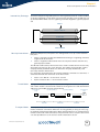


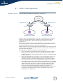
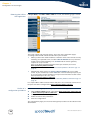
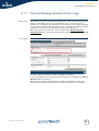
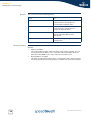


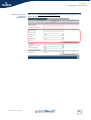
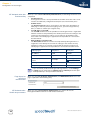
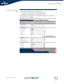

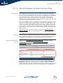
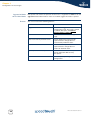

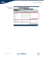
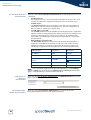
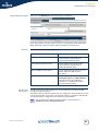
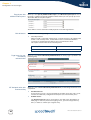
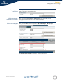
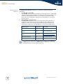
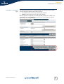
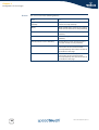
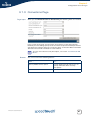
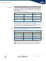
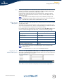


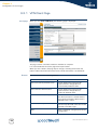
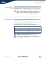
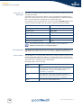
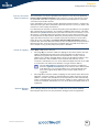
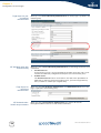
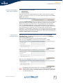
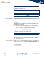
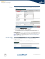

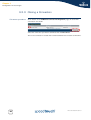
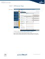
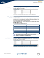
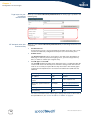
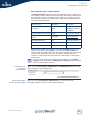
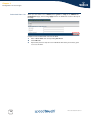
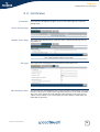
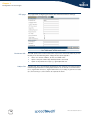

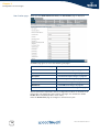
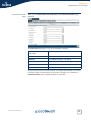
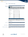
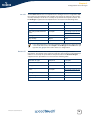


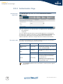
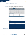
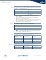
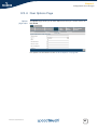
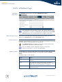
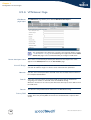

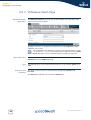
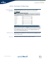
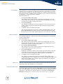

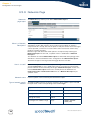

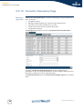
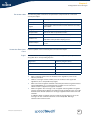
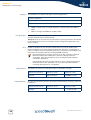
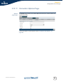
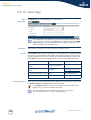
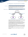
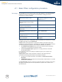
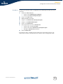
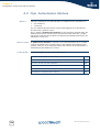
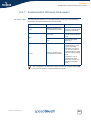
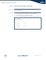
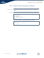
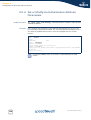
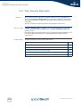

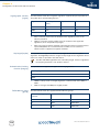

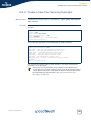
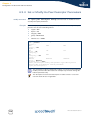
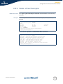
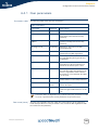
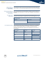
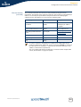
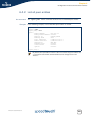
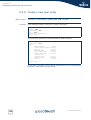
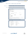
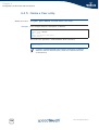
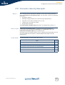
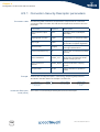
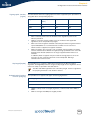
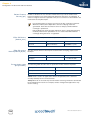

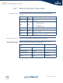
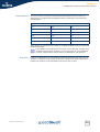
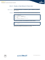

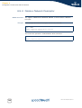
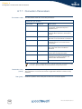

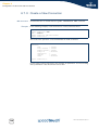
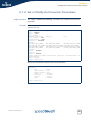
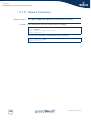
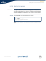
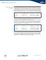

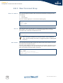
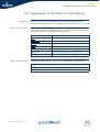
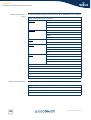
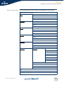

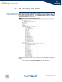
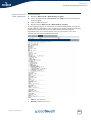
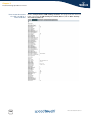
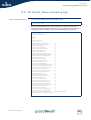
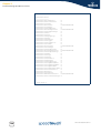
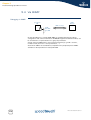


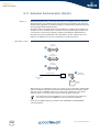

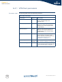
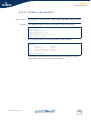
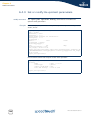


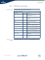
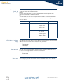
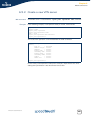
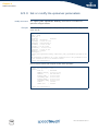
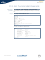

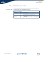

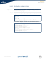
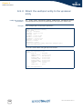
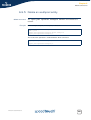
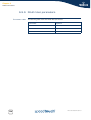
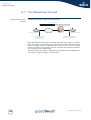
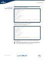
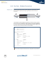
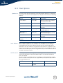
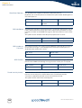
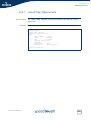
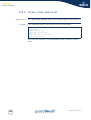
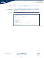
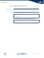
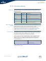
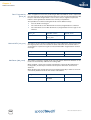
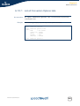
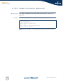
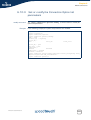
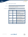
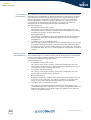


![ABiLINX 1801 取扱説明書[第1版]](http://vs1.manualzilla.com/store/data/006715323_2-e1e615cf5d95655c23373db5a75f8a91-150x150.png)