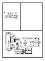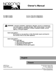
1
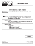
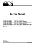
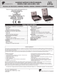
Owner’s Manual
For 1200XX models:
For 120X-IMXX models:
12.0 cu.ft., 2-way, 4-door, R.V. refrigerator.
12.0 cu.ft., 2-way, 4-door, R.V. refrigerator with ice maker.
The letter “X”, in the model numbers above, stands for a letter or numeral which means a
refrigerator option.
!
WARNING: Improper installation, adjustment, alteration, service or maintenance
can cause injury or property damage. Refer to this manual. For assistance or additional information, contact a qualified installer, service
agency, or the gas supplier.
FOR YOUR SAFETY
Do not store or use gasoline or other flammable vapors and liquid in the
vicinity of this or any other appliance.
FOR YOUR SAFETY
If you smell gas:
1. Open windows
2. Don’t touch electrical switches.
3. Extinguish any open flame.
4. Immediately call your gas supplier.
English
French
NORCOLD, Inc.
P.O. Box 4248
Sidney, OH 45365-4248
Norcold Customer Support Dept.
Telephone: 800-543-1219
Fax: 937-497-3183
Web Site: www.norcold.com
Part No. 628937A (2-06)
Table of Contents
Gas Absorption 3 Year Limited Warranty Policy ......................... 2
Gas Absorption Warranty Information ........................................ 3
Gas Absorption Warranty Questions .......................................... 3
Safety Awareness ....................................................................... 4
Safety Instructions ...................................................................... 4
About Your Refrigerator .............................................................. 4
Storage volume ................................................................... 4
Leveling ............................................................................... 4
Operation during travel ........................................................ 4
Food compartment .............................................................. 5
Freezer compartments ........................................................ 5
Crispers .............................................................................. 5
Door bins ............................................................................. 5
Adjustable shelves .............................................................. 5
Door handles ...................................................................... 6
Interior light .......................................................................... 6
Door alarm .......................................................................... 6
Moisture reduction heater ................................................... 6
Temperature control system ............................................... 6
Backup operating system ................................................... 6
Operating the Refrigerator Controls .......................................... 7
Control panel ....................................................................... 7
Automatic mode operation .................................................. 7
Removing air from the propane gas supply lines .............. 7
Set the controls to automatic mode operation ................... 8
Set the controls to manual mode operation ....................... 8
Effects of High Altitude on Propane Gas Operation ................... 8
Ice Maker (Optional) ................................................................... 9
Ice maker operation ............................................................ 9
Refrigerator Care Checklist ..................................................... 10
Defrosting ................................................................................. 10
Cleaning ................................................................................... 10
Interior ............................................................................... 10
Drip tray ............................................................................. 10
Metal doors ........................................................................ 10
Door Sealing ............................................................................. 11
Refrigerator Storage .................................................................. 11
Refrigerator Maintenance Checklist ......................................... 11
Ice Maker Storage (Optional) ..................................................... 11
Refrigerator Maintenance ......................................................... 12
Gas flame appearance ..................................................... 12
Remove and clean the burner orifice ............................... 12
Remove the Refrigerator .......................................................... 13
Reinstall the Refrigerator ......................................................... 13
Replacement Parts .................................................................. 14
Wiring Diagram and Pictorial ................................................... 14
Ice Maker Wiring Pictorial and Diagram (Optional) ................. 14
Fault Codes .............................................................................. 15
NORCOLD - Gas Absorption 3 Year Limited
Warranty Policy
Norcold • P.O. Box 4248 • Sidney, OH • USA • 45365-4248
Provided it is properly installed, properly maintained and placed
under normal service and use, Norcold, Inc. warrants its
refrigeration equipment to be free from defects in material and
workmanship for three years with respect to the equipment’s
component parts, and for two years with respect to the labor to
repair or replace such parts, commencing from the original date
of purchase.
Limitations of warranty
1. This Warranty applies only to Norcold gas absorption
refrigerator operating equipment. This Warranty does not
extend to glassware, electric light bulbs, and replaceable
fuses.
2. This warranty does not apply to parts and assemblies that
have been subjected to misuse, improper installation,
improper or abnormal service, transit damage, recharging of
the cooling system, accident, fire, improper repair, tampering
or abuse.
3. Irrespective of the nature of the warranty protection offered or
claimed, the period of warranty shall in no case extend
beyond three years for component parts and two years for the
labor to repair or replace such parts, commencing from the
original date of purchase of the new equipment.
4. In order to obtain the remedy of repair and replacement, the
refrigerator must be brought to any Norcold Service Center for
warranty service. The end consumer is responsible for all
expenses resulting from any remote service call if the
refrigerator cannot be brought into the Norcold service center.
5. It is the responsibility of the end consumer to have maintenance performed upon the warranted equipment one time
during the second year or before the beginning of the third
year after original purchase. Such maintenance is required to
maintain this warranty in effect and failure to perform such
maintenance will void the remainder of the warranty. Required maintenance during the second year or before the
third year after purchase is cleaning and checking of the
following: Burner, Flue, Spiral Baffle, Roof Cap Screen, and
Control Board Sequence.
LIMITATION OF REMEDY
1. THE RESPONSIBILITY OF NORCOLD UNDER THIS OR ANY
WARRANTY IS LIMITED TO THE REPAIR OR REPLACEMENT
(AT NORCOLD’S OPTION) OF THE DEFECTIVE PART OR
ASSEMBLY.
Owner’s Manual 2
2. IN NO EVENT AND UNDER NO CIRCUMSTANCES SHALL
NORCOLD BE RESPONSIBLE UNDER THIS LIMITED WARRANTY FOR ANY OTHER CHARGE WHATSOEVER, INCLUDING
BUT NOT LIMITED TO CHARGES OR CLAIMS FOR LABOR,
LOST BUSINESS, LOST TIME, LOST PROFITS, LOSS OF USE,
OR ANY KIND OF INCIDENTAL OR CONSEQUENTIAL DAMAGES, HOWEVER DENOMINATED OR DESCRIBED. THE
REMEDY UNDER THIS WARRANTY IS LIMITED TO REPLACEMENT OR REPAIR.
3. SOME STATES DO NOT ALLOW THE EXCLUSION OR
LIMITATION OF INCIDENTAL OR CONSEQUENTIAL DAMAGES,
SO THE ABOVE EXCLUSION MAY NOT APPLY TO YOU.
DISCLAIMER OF OTHER WARRANTIES
THIS WARRANTY IS EXPRESSLY IN LIEU OF ALL OTHER
WARRANTIES EITHER EXPRESSED OR IMPLIED. ALL OTHER
WARRANTIES, EXPRESSED OR IMPLIED, INCLUDING ANY
WARRANTY OF MERCHANTABILITY OR FITNESS FOR A PARTICULAR PURPOSE, ARE HEREBY DISCLAIMED AND EXCLUDED.
Legal rights
This warranty gives you specific legal rights, and you may have
other legal rights, which vary from state to state.
Gas Absorption Warranty Information
Your refrigerator is made to provide the ultimate in cooling
satisfaction and will serve you reliably in the years to come.
Norcold refrigerators are the only RV refrigerators made in the
United States and offer a standard limited three-year warranty.
Norcold also offers an additional warranty coverage plan which
extends the standard limited three-year warranty. To activate
your three-year limited warranty and to receive an invitation to
participate in the extended warranty plan, complete and mail the
warranty registration supplied.
Help us to help you.
Write the model number and serial number below for future
reference. These numbers are on the serial plate in the
refrigerator. The serial plate is located in the fresh food
compartment on the top right hand side. Use these numbers
when receiving service or in any correspondence concerning
your refrigerator.
Model number ___________ Serial number ___________
If a problem occurs with your refrigerator, contact any of the
service centers throughout the United States and Canada. To
find an authorized Norcold Service Center near you, please
telephone the Norcold Customer Support Dept. at 800-5431219 (option-1) or visit our web site at www.norcold.com.
Norcold is committed to providing products that are in harmony
with the environment. Your Norcold refrigerator meets all
environmental safety standards.
Gas Absorption Warranty Questions
About your warranty
This warranty coverage begins on the original date of purchase by the
consumer purchaser and is the only warranty for the Norcold refrigerator. In no case will the Limited Warranty extend beyond two (2) years
for labor and three (3) years for parts and freight. Norcold reserves
the right to change design or specifications of a refrigerator without
obligation to modify previously produced refrigerators. There are no
other warranties, either expressed or implied.
What is coverd by this warranty?
- Defects in material and workmanship.
- Parts and labor for two (2) years
- Parts only for the third year if the required maintenance is
performed.
- Freight (ground service only) for shipment of a replacement part
and for return of the defective part.
What is not covered by this warranty?
- Shipping methods other than ground service.
- Defects in glassware, electric light bulbs, and replacement fuses.
- Adjustment of the burner electrode.
- Cleaning of the burner.
- Fees for mobile repair service.
- Mileage or travel expenses to obtain warranty service.
- Expenses for required maintenance as specified in the Limited
Warranty and in the Owner’s Manual.
- Incidental or consequential loss or damage including but not limited
to charges or claims for labor (including labor when no parts are
used for a repair), lost business, lost time, lost profits, lost food,
and lost use.
- Replacement parts that are not manufactured or supplied by
Norcold.
- Defect a of a part or assembly when the defect originates from
misuse, improper installation, improper or abnormal service, transit
damage, recharging of the cooling system, accident, fire, improper
repair, tampering, or abuse.
What will Norcold do?
For a refrigerator that is properly installed, maintained, and used as
specified in the Installation/Owner’s Manuals, Norcold responsibilities
are:
- Limited to the repair and replacement of parts.
- To provide no charge parts and labor for two (2) years.
- To provide no charge parts only for year 3 if the required
maintenance is performed.
- To provide freight (ground service only) for shipment of a
replacement part and for return of a defective part for three (3)
years.
What will the refrigerator owner do?
To obtain warranty service, the refrigerator owner responsibilities are:
- To use, service, and maintain the refrigerator as specified in the
Installation/Owner’s Manuals.
- To deliver the warranted product to an authorized Norcold Service
Center for warranty repair.
- To show proof that the refrigerator is within warranty coverage.
- To have the required maintenance performed by an authorized
Norcold Service Center one time during year 2 of the Limited
Warranty.
- To pay to have the required maintenance performed.
- To mail paid receipt to Norcold showing required performed before
expiration of year 2 of the Limited Warranty.
- To show proof of the required maintenance before requesting
warranty service in year 3 of the Limited Warranty.
What rights do you have?
The warranty gives you specific legal rights. You may also have other
rights which vary from state to state.
Owner’s Manual 3
- Do not spray liquids near electrical outlets, connections, or the refrigerator components. Many liquids are
electrically conductive and can cause a shock hazard,
electrical shorts, and in some cases fire.
Safety Awareness
Read this manual carefully and understand the contents before
you use the refrigerator.
- The refrigerator cooling system is under pressure. Do
not try to repair or to recharge a defective cooling
system. The cooling system contains sodium chromate. The breathing of certain chromium compounds
can cause cancer. The cooling system contents can
cause severe skin and eye burns, and can ignite and
burn with an intense flame. Do not bend, drop, weld,
move, drill, puncture, or hit the cooling system.
Be aware of possible safety hazards when you see the safety
alert symbol on the refrigerator and in this manual. A signal word
follows the safety alert symbol and identifies the danger of the
hazard. Carefully read the descriptions of these signal words to
fully know their meanings. They are for your safety.
!
WARNING: This signal word means a hazard, which if
!
CAUTION: This signal word means a hazard, which if
ignored, can cause small personal injury or much property
damage.
Safety Instructions
!
- At regular intervals, make sure that the refrigerator flue
the burner, the vent areas, and the ventilation air
pathway between the vents are completely free from
any flammable material or blockage. After a period of
storage, it is especially important to check these areas
for any flammable material or blockage caused by
animals.
ignored, can cause dangerous personal injury, death, or
much property damage.
!
- The rear of the refrigerator has sharp edges and
corners. To prevent cuts or abrasions when working
on the refrigerator, be careful and wear cut resistant
gloves.
WARNING:
- The storage of flammable materials behind or around
the refrigerator creates a fire hazard. Do not use the
area behind the refrigerator to store anything, especially flammable materials (gasoline, cleaning
supplies, etc.)
- Do not remove the round ground prong from the AC
power cord of the refrigerator or the ice maker
(optional). Do not use a two prong adapter or an
extension cord with either AC power cord.
- A circuit overload can result in an electrical fire if the
wires and/or fuses are not the correct size. Use only
the wire and fuse sizes as writtten in the “Installation
Manual”.
- Incorrect installation, adjustment, change to, or
maintenance of this refrigerator can cause personal
injury, property damage, or both. Have service and
maintenance work done by your dealer or by an
Norcold authorized service center.
- Disconnect both the AC and DC power sources before
doing any maintenance work on the refrigerator. All
service work on this refrigerator must be done by a
qualified service technician.
- Do not bypass or change the refrigerator’s electrical
components or features.
- When you discard an appliance, remove all doors to
prevent accidental entrapment and suffocation.
Owner’s Manual 4
CAUTION:
About Your Refrigerator
Storage Volume:
This refrigerator is made for storage of foods and frozen food
and for making ice.
Total capacity
Freezer Compartments
Fresh Food Compartment
12.0 cubic feet
3.6 cubic feet total
8.4 cubic feet
Leveling:
!
CAUTION: The refrigerator is made to operate within 3°
off level side-to-side and 6° off level front-to-back (as
looking at the front of the refrigerator). Operating it at
more than these limits can cause damage to the cooling
system and create a risk of personal injury or property
damage. Make sure the vehicle is level before you
operate the refrigerator.
Operation during travel:
While the refrigerator should be level when the vehicle is
stopped, performance during travel is not usually effected.
Food compartment:
Crispers:
Start up the refrigerator (see “Operating the Refrigerator
Controls”)and let it cool for eight hours before loading with food.
If the refrigerator does not start to cool down after about two
hours, contact your dealer or a Norcold authorized service
center.
The crispers are located at the bottom left side of the fresh food
compartment and supply a storage area to preserve fruit and
vegetable freshness. Make sure that you always push the
crispers fully in. The glass crisper covers are made so that you
can remove them.
For the best cooling performance:
NOTE: Do not wash the crispers in a dishwasher. The crispers
are not dishwasher safe.
- Let air move freely inside the entire food compartment.
To remove the glass crisper covers [135] (See Art01118):
- Do not cover the shelves with plastic, paper, etc.
- Remove the crispers [136].
To decrease the amount of ice that collects on the cooling fins:
- Cover all liquids and moist foods.
- Let all hot foods cool before putting them in the refrigerator.
- Remove the screw from the top right side of the crisper
support wall [137].
- Remove the screws [41] from the retainer [54] on the left
side of the refrigerator (See Art00992).
- Do not open the door any longer than necessary.
- Remove the retainer.
Freezer compartments:
The freezer compartments are made to keep pre-frozen food
frozen and not to quick freeze food.
NOTE: Do not put other items on the ice tray while the water is
freezing. The water freezes more rapidly if the thermostat is at the COLDEST position.
Door handles:
During travel, the door latch prevents the door from opening.
When closing each door, push the door toward the refrigerator
until you hear a “click” sound.
To open each door, pull the handle away from the refrigerator
(See Art00990).
During storage, the storage latch prevents the door from
completely closing. Use it to prevent odors when the refrigerator is stored for an extended period of time.
- Remove the glass crisper covers.
- Remove the crisper support wall.
Tall bottle and gallon storage drawer:
The tall bottle and gallon storage drawer [138] is located at the
bottom right side of the fresh food compartment and supplies a
storage area for items such as 2-liter bottles or gallon milk
containers (See Art01118). This drawer has a divider which
prevents items from moving and/or overturning while the vehicle
is in transit. Make sure that you always push the drawer fully in.
The divider fits down into grooves on the inside of the drawer.
The divider also fits at the rear of the drawer so that you can use
all of the capacity of the drawer.
NOTE: Do not wash the drawer or divider in a dishwasher. The
drawer and divider are not dishwasher safe.
Door bins:
To operate the storage latch (see Art00991), open each door
about 1/2 inch, hold the door handle in the open position, and
push the storage latch [55] into the cutout [56] of the strike plate.
Do not use the storage latch as a travel latch because the doors
will not be fully closed.
Movable door seal:
The movable door seal [134] is located on the left door of the
fresh food compartment (See Art01109). It provides the correct
seal when both doors of the fresh food compartment are
closed. When the left door of the fresh food compartment
opens, the movable door seal moves so that it is flat against
the edge of the door. To avoid possible damage to the movable
door seal, make sure that it is flat against the edge of the door
before you close the door
You may put the door bins [52] of the freezer and fresh food
compartment in a location that best meets your needs (See
Art01114). To remove the bins, lift them over the locator and pull
them forward. To install the bins, push them onto the locator.
NOTE: Do not wash the door bins in a dishwasher. The door
bins are not dishwasher safe.
Adjustable shelves:
The shelves in the freezer and the fresh food compartment are
made so you can remove them or move them.
To remove or move the shelf of the freezer:
- Pull the shelf forward out of the slot.
- Push it fully into the slot that you wish.
Owner’s Manual 5
To remove or move the shelves of the fresh food compartment:
- Remove the screws [41] from each retainer [54] on the side
of the refrigerator (See Art00992).
Temperature control system:
- Pull each shelf forward out of the slot.
Although the refrigerator is not frost -free, it is made to limit frost
on the cooling fins. At regular intervals, the temperature control
system automatically melts most of the frost from the cooling
fins. The water from the cooling fins drains into a collection cup
that is attached to the back of the refrigerator. The heat of the
cooling system evaporates the water from the collection cup.
- Push each fully into the slot that you wish.
Backup operating system:
- Install both retainers with the screws.
This refrigerator has a backup operating system. The backup
operating system allows the refrigerator to continue to cool if the
temperature sensor of the refrigerator should fail.
- Remove both retainers.
Interior light:
The interior light is at the top of the fresh food compartment. It
comes on when the refrigerator is ON and the door is open. To
replace the bulb:
1. Remove the DC power supply wires from the power board at
the rear of the refrigerator.
2. Remove the cover [57] by pulling it toward the front of the
refrigerator (See Art00988).
3. Remove the light bulb [58] from the holder [59].
NOTE: Use only a GE#214-2 bulb as the replacement bulb.
This bulb is available at most retail automotive parts
centers.
4. Install the replacement bulb.
5. Install the cover.
6. Connect the DC power supply wires to the power board at
the rear of the refrigerator.
Door alarm:
The refrigerator has an alarm to alert you if the fresh food
compartment door is not closed. The refrigerator continues to
operate, but if the fresh food compartment door is open and the
interior light remains on for two minutes:
- An audible alarm starts.
- “dr” appears in the center display.
- The interior light automatically turns off.
Close the door to silence the alarm.
Moisture reduction heaters:
The refrigerator has heaters that prevent moisture from forming
on the center divider between the two doors of the freezer
compartment and on the movable door seal. The heaters
operate only when the refrigerator is ON and the DC power is
sufficient. The heater in the movable door seal also only
operates when the left door of the fresh food compartment is
closed.
Owner’s Manual 6
If this failure occurs:
- The refrigerator automatically changes to the backup
operating system.
- When you push the SET TEMP button, the temperature
setting flashes in the center display for ten seconds.
- After the temperature setting flashes, the mode of
operation appears in the center display.
- The backup operating system can overfreeze or thaw the
contents of the freezer and the fresh food compartment.
- Make sure the temperatures of the freezer and the fresh
food compartment are satisfactory.
NOTE: If you open the door(s) too often, the temperatures inside the freezer and fresh food compartment do not become stable. Allow the refrigerator to operate for about one hour after each
adjustment change before you examine the
contents. The number “9” is the coldest
temperature setting.
- If the temperature is too warm, push and hold the
SET TEMP button to raise the temperature setting
by one number.
- If the temperature is too cold, push and hold the
SET TEMP button to lower the temperature setting
by one number.
- Have the refrigerator serviced by your dealer or a Norcold
authorized Service Center as soon as possible.
Operating the Refrigerator Controls
AC Operation
120 volts AC
(108 volts min.-132 volts max.)
Propane gas operation:
Propane gas
(11 inches water column pressure)
12 volts DC - control voltage
(10.5 volts min. - 15.4 volts max.)
The refrigerator operates on these energy sources. Operation
out of these limits can damage the refrigerator electrical
components and will void the warranty.
Control panel:
The MODE button [31] controls the operation mode of the
refrigerator:
- Push and hold the MODE button and each of the operating
modes of the refrigerator show one at a time in the center
display.
- There is one automatic mode of operation and two
manual modes of operation.
- When the mode of operation that you wish shows in the
center display, release the MODE button.
NOTE: If you should forget in what mode your refrigerator is operating, push and release the
MODE button to show the current mode of
operation in the center display for 10 seconds.
Automatic mode operation:
When the refrigerator is in AUTO mode, it automatically uses the
most efficient energy source that is available for operation.
During operation, if a more efficient energy source becomes
available, the refrigerator controls change from the current
energy source to the more efficient energy source as follows:
The refrigerator control panel (See Art01333) is between the
freezer compartment and the fresh food compartment. To
maintain the operating control functions of the refrigerator, a 12
volt DC power supply is necessary. The refrigerator receives
DC power from the 12 volt system of the vehicle; either an
auxillary battery, a converter, or the vehicle engine battery.
- The first choice is AC operation if 120 volts AC is available to
the refrigerator.
- The second choice is propane gas operation if 120 volts AC
is not available to the refrigerator.
Removing air from the propane gas supply lines:
The ON / OFF button [30] starts and shuts down the refrigerator:
- To turn on the refrigerator, push and release the ON / OFF
button.
- To turn off the refrigerator, push the ON / OFF button for one
second and then release.
The SET TEMP button [32] controls the temperature adjustment
of the freezer and the fresh food compartment. The temperature
adjustment that you select does not change if the operation
mode of the refrigerator changes.
For safety reasons, the burner is made to ignite on propane gas
within a specified amount of time. When starting the refrigerator
for the first time, after storage, or after replacing propane gas
tank, the propane gas supply lines can have air in them. Due to
the air in the gas supply lines, the burner may not ignite on
propane gas within the specified amount of time.
To remove the air from the propane gas supply lines:
- Make sure that valve of the propane gas tanks(s) is open.
- Push the ON / OFF button to turn the refrigerator on.
- Push the SET TEMP button and the temperature setting (the
numbers “1-9”) show in the center display [33].
- Push and hold the MODE button until the letters “LP” show
in the center display.
- The number “9” is the coldest temperature setting.
- Push and hold the SET TEMP button and the temperature
setting changes.
- Release the SET TEMP button when the temperature
setting that you wish appears.
- This means that the refrigerator is operating on
propane gas.
- If the air in the propane gas supply lines prevents the
burner from ignition on propane gas, the fault codes
“no” and then “FL” will appear in the center display and
you will hear an alarm sound.
- After ten seconds, the temperature setting will go out and
only a green power ON light remains.
Owner’s Manual 7
- Push and hold the ON / OFF button for one second and
then release to silence the alarm.
- Push the ON / OFF button to turn the refrigerator on.
- The refrigerator will start a 30 second trial for
ignition.
- During the 30 second trial for ignition, the refrigerator controls open the gas safety valve and the
igniter makes sparks.
- When no fault code shows and only the power indicator
remains, this means that the refrigerator is operating on
propane gas in the manual mode.
- At this time, all of the air is removed from the propane
gas supply lines and you may select AUTO mode of
operation if you wish.
- Depending on how much air may be in the propane gas
supply lines, you may need to repeat the 30 second trial for
ignition two or three times.
- If the burner does not ignite on propane gas after two or
three attempts, stop and consult your local dealer or an
authorized Norcold Service Center.
- If neither 120 volts AC nor propane gas is available to the
refrigerator:
- The fault codes “no” “AC” and then “no” “FL” show in
the center display and an audible alarm sounds.
If an energy source is available to the refrigerator, but is not
operating correctly:
- A fault code shows in the center display.
- The refrigerator controls try to change to a less efficient
energy source.
- If a less efficient energy source is not available:
- An audible alarm starts.
- A fault code shows in the center display.
- Refer to the “Fault Codes” section of this manual.
Set the controls to manual mode operation:
- Push the ON / OFF button to turn the refrigerator on.
- Push and hold the MODE button until the letters “ AC” show
in the center display and then release.
Set the controls to automatic mode operation:
- Push the ON / OFF button to turn the refrigerator on.
- Push and hold the MODE button until the letters “AU” show
in the center display and then release.
- If 120 volts AC is available to the refrigerator:
- After ten seconds, the “AC” goes off and only a green
power ON light remains.
- Push and hold the MODE button until the letters “LP” show
in the center display and then release.
- After ten seconds, the “LP” goes off and only a green
power ON light remains.
- The letters “AU” and then “AC” show in the center
display.
- After ten seconds, the “AU” and then “AC” go off and
only a green power ON light remains.
Effects of High Altitude on Propane Gas
Operation
- This means that the refrigerator is operating on AC
electric.
- If 120 volts AC is not available to the refrigerator:
When you operate the refrigerator on propane gas at altitudes
higher than 5500 feet above sea level:
- The letters “AU” and then “AC” show in the center
display.
- You may experience reduced cooling performance of the
refrigerator.
- After five seconds, the “AU” and then “LP” show in the
center display.
- You may experience burner outages.
- After ten seconds, the “AU” and the “LP” go off and only
a green power ON light remains.
- This means that the refrigerator is operating on
propane gas.
Owner’s Manual 8
To avoid these possible problems, Norcold recommends that
you operate the refrigerator on AC when at altitudes higher than
5500 feet above sea level.
Ice Maker (Optional)
Refrigerator Care Checklist
The ice maker is assembled to the refrigerators at the factory as
optional equipment. If the refrigerator does not have a factory
installed ice maker, one cannot be added to the refrigerator at a
later time.
Your refrigerator will give you years of trouble free service if you
do these simple checks every three to six months:
The ice maker is fully automatic and will operate in ambient
temperatures as low as 0° F. To allow operation at temperatures between 0° F and 32° F., the ice maker has a heater on
the solenoid water valve and on the water line between the
solenoid valve and the ice maker. At temperatures below 0° F,
store the ice maker as written in the “Ice Maker Storage” section
of this manual.
!
CAUTION: The water line heater does not protect the
water supply line from the vehicle shut off valve to the
solenoid valve on the back of the refrigerator.
When the freezer temperature of the refrigerator is low enough,
the ice maker opens the water solenoid valve and fills the mold.
The ice maker ejects the frozen ice into a storage bin. As the
storage bin fills, the ice raises the shut-off arm until it turns off
the ice maker. As you use the ice and lower the ice level in the
storage bin, the shut-off arm also lowers. This turns the ice
maker ON and begins the process of making ice.
The ice maker operates on:
- Cold potable water at a pressure of 15 psi - 125 psi.
- Keep the food compartment and the freezer clean. See
“Cleaning”.
- Defrost the refrigerator as necessary. See “Defrosting”.
- Make sure the door seals correctly. See “Door Sealing“.
- Be aware of any cooling changes that are not because of
weather, loading, or gas control changes. If changes occur,
contact your dealer or service center.
- Make sure the gas supply is propane gas only and not
butane or a butane mixture.
- When in propane gas operation, examine the appearance
of the flame. See “Gas Flame Appearance”.
- Make sure the air flow in the lower intake vent, through the
refrigerator coils and condenser, and out the upper exhaust
vent is not blocked or decreased.
- Make sure the area behind the refrigerator is clear. Do not
use the area behind the refrigerator for storage of anything,
especially combustible materials, especially gasoline and
other flammable vapors and liquids.
- 120 Volts AC (108 VAC min. - 132 VAC max.).
Ice maker operation:
1. Make sure the ice maker AC power cord is plugged into a
receptacle.
2. Open the water shut off valve of the vehicle.
NOTE: Make sure that the ice maker arm can move freely and
does not touch the frozen foods in the freezer.
3. Push the ice maker arm down to the ON position [60] (See
Art01015).
!
CAUTION: If you operate the refrigerator without
connecting the water supply line and/or opening the
water shut off valve of the vehicle, make sure the ice
maker arm is up in the OFF position.
4. Allow the freezer to cool enough and ice production will begin
to fill the storage bin [61].
NOTE: New plumbing connections and/or impurities in the
water supply line after winterizing can cause the first
ice to be discolored or have an odd flavor.
Defrosting
The cooling fins of the refrigerator operate at below freezing
temperature and will naturally form frost from humidity, which is
always present in the air. The humidity inside the refrigerator
increases:
- with higher outside temperature and humidity.
- with the storage of non-sealed fresh foods or warm foods.
- with the amount of time that the door(s) are open.
- with any air leakage into the refrigerator.
Although the refrigerator is not frost -free, it is made to limit frost
on the cooling fins. At regular intervals, the temperature control
system automatically melts most of the frost from the cooling
fins. The water from the cooling fins drains into a collection cup
that is attached to the back of the refrigerator. The heat of the
cooling system evaporates the water from the collection cup.
5. To stop the ice maker, push the ice maker arm up to the OFF
position [62].
Owner’s Manual 9
It is normal for frost to collect inside the freezer. Excess frost
decreases the cooling performance of the refrigerator. Defrost
the refrigerator and freezer as necessary:
- Wash the interior with a mild cleaner or a solution of liquid
dish detergent and warm water.
- Rinse with a solution of baking soda and clean water.
- Remove all food from the refrigerator.
- Dry with clean cloth.
- Turn the refrigerator OFF.
- Put all food in the refrigerator.
NOTE: Defrosting the refrigerator makes excess water inside
the refrigerator.
- Remove the drain hose from the drip cup at the rear of the
refrigerator.
- Put the drain hose into a half-gallon or larger container to
capture water.
Drip tray:
To remove and clean the drip tray:
- Remove the screws [41] from the retainers [54] on each
side of the refrigerator (See Art00992).
- Remove the retainers.
- Put dry towels (etc.) inside the refrigerator and freezer to
absorb melted frost.
!
CAUTION: High temperatures can cause the inside
surfaces of the refrigerator to warp or melt. Do not use
pans of HOT water, a hair dryer, or any other high
temperature devices to defrost the refrigerator. Do not
use any hard or sharp objects to remove frost. Damage
to the interior of the refrigerator can occur.
- Pull the self that is in front of the drip tray forward to remove
from the refrigerator
- Make sure that the drip tray is empty of water.
- Pull the drip tray out of the drain hose.
- Pull the drip tray forward to remove from the slots in the
refrigerator cabinet.
- To increase the speed of defrosting, put pans of WARM
water in the refrigerator and freezer.
- Clean the drip tray.
- Remove the wet towels (etc.) and dry the interior.
- Push the drip tray back into the slots in the refrigerator
cabinet.
- Remove the drain hose from the large container and put the
drain hose back into the drip cup.
- Push the drip tray back into the drain hose.
- Remove the large container from the enclosure.
- Put the wire shelf back in the original position.
- Start up the refrigerator.
- Install the retainers with the screws.
- Allow the refrigerator to cool down.
Metal doors:
- Return all food to the refrigerator.
To clean the metal doors:
Cleaning
- Wash the doors with a mild cleaner or a solution of liquid
dish detergent and warm water.
- Rinse with clean water.
Interior:
- Dry with clean cloth.
A good time to clean the refrigerator is just after you defrost it.
Clean the inside of the refrigerator as often as necessary to
avoid food odors:
NOTE: Do not use abrasive cleaners, chemicals, or
scouring pads because they can damage the
metal doors.
- Remove all food from the refrigerator.
NOTE: Do not use abrasive cleaners, chemicals, or
scouring pads because they can damage the
interior of the refrigerator.
Owner’s Manual 10
Door Sealing
- Make sure the propane gas pressure is 11 inches water
column.
- Adjust if needed.
Check the seal of the doors (See Art00980).
If either door does not seal correctly, excess frost will collect
inside the refrigerator. Make sure the doors seal correctly:
- Close each door on a piece of paper that is about the size
and thickness of a dollar bill.
- Make sure the combustion seal is complete and intact.
- Replace or repair it if needed.
- Make sure the burner and the burner orifice are clean.
- Clean if needed.
- Gently pull the paper.
- You should feel a slight drag between the gasket and
the cabinet.
- Make sure the electrode is clean and the spark gap is 1/8 3/16 inch.
- Adjust if needed.
- Do this on all four sides of the door.
- If you do not feel a slight drag on the
paper, the door does not seal correctly.
- Have your dealer or an authorized Norcold Service
Center correct the seal of the door.
Refrigerator Storage
Before the refrigerator is stored for an extended (seasonal)
period of time:
- Defrost and clean the interior of the refrigerator.
- Close the doors with the storage latch.
If the refrigerator is stored for an extended period of time, before
start up:
- Make sure there are no obstructions in the vents, the
ventilation air pathway, the burner, the orifice, or the flue
area.
- Make sure the AC voltage is 108 -132 volts and the DC
voltage is 10.5 - 15.4 volts.
Ice Maker Storage (Optional)
To prepare the ice maker for seasonal storage:
1. Close the vehicle water supply valve to the ice maker.
2. Push the ice maker arm up until it locks into the OFF
position.
3. Remove the garden hose adapter from the water solenoid
valve.
4. Remove the ice maker water line from the water solenoid
valve
- Do not unwrap the water line heater wires from around the
water solenoid valve.
5. Drain all of the water from both the water supply line and the
ice maker water line.
Refrigerator Maintenance Checklist
6. Put the end of the water supply line, the end of the ice maker
water line, and the water solenoid valve each into a clean
plastic bag.
Read and understand the following maintenance sections of
this manual.
7. Use tape to close each plastic bag around the water lines
and the water solenoid valve.
NOTE: Norcold is not responsible for installation, adjustment, alteration, service, or maintenance performed
by anyone other than a qualified RV dealer or a
Norcold authorized service center.
To use the ice maker after seasonal storage:
Have a qualified RV dealer or a Norcold authorized service
center do these annual safety and maintenance checks:
!
CAUTION: Do not operate the ice maker when the
ambient air temperature is 0° F. or lower. Damage to the
water solenoid valve and the water supply line can occur.
- Examine the gas supply lines for leaks.
- Replace or repair if needed.
Owner’s Manual 11
1. Remove the tape and plastic bags from the end of the water
supply line, the end of the ice maker water line, and the water
solenoid valve.
Remove and clean the burner orifice:
Your dealer or Norcold authorized service center must do this
procedure.
2. Connect the ice maker water line to the water solenoid valve.
Remove and clean the burner orifice (See Art00956):
3. Connect the garden hose adapter to the water solenoid
valve.
- Close the valve at the propane gas tank(s).
4. Push the ice maker arm down into the ON position.
- Push the ON / OFF button to shut down the refrigerator.
5. Open the vehicle water supply valve to the ice maker.
- Open the lower intake vent.
NOTE: You should discard and not use the first two batches of
ice cubes. It will take about three cycles for the ice
maker to make fully formed and clean ice cubes.
!
CAUTION: The burner box cover can be hot. Wear
gloves to avoid burns.
- Remove the burner box cover by removing the screw(s).
Refrigerator Maintenance
!
WARNING: To avoid possible propane gas leaks,
always use two wrenches to loosen and tighten the
gas supply line connections.
Gas flame appearance:
- Remove the flare nut from the orifice assembly [77] (See
Art00956).
While in LP GAS operation, examine the appearance of the gas
flame:
- Remove the orifice assembly from the burner [78].
- Push the TEMP SET button until the number “9” appears in
the center display.
- Open the lower intake vent.
!
CAUTION: The burner box cover can be hot. Wear
gloves to avoid burns.
- Look at the gas flame [75] (See Art00955).
!
WARNING: Do not try to remove the orifice [79] from
the orifice adapter [80] when cleaning. Removal will
damage the orifice and seal of the orifice and can
cause a propane gas leak. Leaking propane gas can
ignite or explode which can result in dangerous
personal injury or death. Do not clean the orifice with a
pin or other objects.
- Clean the orifice assembly with air pressure and alcohol
only.
- The flame should be:
- a darker blue color on the inside of the flame and
a lighter blue color on the outside of the flame.
- Using a wrench, assemble the orifice assembly to the
burner.
- Assemble the flare nut to the orifice assembly.
- a constant shape without flickering.
- Examine all of the connections for gas leaks.
- Contact your dealer or Norcold authorized service
center if the flame is:
- yellow
- flickering or changing shape.
- Make sure the flame does not touch the inside of the
flue tube [76].
- If the flame touches the inside of the flue tube, contact
your dealer or Norcold authorized service center.
- Close the burner box door.
Owner’s Manual 12
- Assemble the burner box cover.
Remove the Refrigerator
Reinstall the Refrigerator
Your dealer or Norcold authorized service center must do this
procedure.
Your dealer or Norcold authorized service center must do this
procedure.
!
!
CAUTION: The rear of the refrigerator has sharp edges
and corners. To prevent cuts or abrasions when working
on the refrigerator, be careful and wear cut resistant
gloves.
WARNING: To avoid possible propane gas leaks,
always use two wrenches to loosen and tighten the gas
supply line connections.
1. Close the valve at the propane gas tank(s).
2. Remove the black AC power cord and the white ice maker AC
power cord (optional) from the receptacle.
3. Remove the DC wiring from the refrigerator:
- Put a mark on the DC wires so you can put them back in the
correct location.
- Remove the DC fuse or remove the DC wiring from the
battery or the converter.
- Remove the DC wires from the refrigerator.
4. Open the lower intake vent and remove the gas supply line
from the bulkhead fitting of the refrigerator.
5. Remove the plastic plugs from the mounting flanges of the
refrigerator.
6. Remove the screws from the upper and lower mounting
flanges on the front of the refrigerator.
7. Remove the screws from the mounting flange at the rear of
the refrigerator.
8. Remove the refrigerator from the opening.
!
WARNING: Make sure the combustion seal is not
broken, is completely around the refrigerator mounting
flanges, and is between the mounting flanges and the
wall of the enclosure. If the combustion seal is not
complete, exhaust fumes can be present in the living
area of the vehicle. The breathing of exhaust fumes can
cause dizziness, nausea, and in extreme cases, death.
1. Push the refrigerator completely into the enclosure.
2. Install the screws in the mounting flange at the rear of the
refrigerator.
3. Install the screws from the upper and then the lower mounting flanges on the front of the refrigerator.
4. Put the plastic plugs into the mounting flanges of the
refrigerator.
!
WARNING: To avoid possible propane gas leaks,
always use two wrenches to loosen and tighten the LP
gas supply line connections.
5. Attach the gas supply line to the bulkhead fitting of the
refrigerator.
6. Open the valve at the propane gas tank(s).
!
WARNING: Do not allow the leak checking solution to
touch the electrical components. Many liquids are
electrically conductive and can cause electrical shorts
and in some cases, fire.
7. Using a leak detecting solution, examine the gas supply line
for leaks.
8. Connect the DC wiring to the refrigerator:
- Connect the DC wires to the refrigerator.
- Install the DC fuse or connect the DC wiring to the battery or
the converter.
9. Connect the black AC power cord and the white ice maker AC
power cord (optional) to the receptacle.
Owner’s Manual 13
Replacement Parts
Ice Maker Wiring Pictorial and Diagram
(Optional)
You may purchase replacement parts through your local RV
dealer or authorized Norcold Service Center.
The parts of the ice maker wiring pictorial and diagram are (See
Art01500):
Wiring Diagram and Pictorial
The parts of the wiring diagram are (See Art01769):
The parts of the wiring pictorial are (See Art01770):
A .................................................................... Temperature switch
B .................................................................................. AC heaters
C .................................................................................. Thermister
D ................................................................................ Interior light
E .............................................................................. Divider heater
F .............................................................................. Door contacts
G ............................................................................ Door switches
H ................................................................... Gas valve (optional)
I ............................................................................................. Fans
J ........................................ Ice maker water line heater (optional)
K ...................................................... Water valve heater (optional)
L ...................................... Dispenser water line heater (optional)
M ................................... Dispenser water valve heater (optional)
N ......................................................... Dispenser valve (optional)
O ............................................................. Fan temperature switch
P .................................................... Temperature switch (optional)
Q ...................................................... Dispenser switch (optional)
R .......................................................... Dispenser light (optional)
S .......................................................................... Igniter (optional)
T .......................................................................... Chassis ground
U .......................................................... Movable door seal heater
V ............................................ Movable door seal housing ground
1 ........................................................................ Switched 12 VDC
2 ......................................................... Fused continuous 12 VDC
3 ........................................................................ Communications
4 ............................................................................ Display ground
5 .......................................................................... Auxilliary ground
6 ...................................................................... Auxilliary +12 VDC
7 ......................................................................... Divider + 12 VDC
8 .................................................................... Gas valve + 12 VDC
F1 .......................................................................... 5 Amp DC fuse
F2 ........................................................................... 8 Amp AC fuse
Owner’s Manual 14
109 ..................................................... 120V AC Hot / smooth
110 ................................................. 120 VAC Neutral / ribbed
111 ................................................................... Ground screw
114 ................................................................... Thermal fuse
44 ......................................................... Solenoid water valve
115 ......................................................................... Ice maker
116 ...................................................................... Mold heater
96 ........................................................................ Thermostat
117 ................................................................. Shut off switch
118 ......................................................................... Fill switch
119 ...................................................................... Hold switch
120 ................................................................................ Motor
Fault Codes
Fault Codes
Fault Code Meaning
No
display.
DC voltage is
unavailable to the
refrigerator control
panel or the
refrigerator is OFF.
" dr "
Audible alarm also.
The door was open for
more than 2minutes.
Corrective Actions
Check:
- That the refrigerator is ON.
- That the battery charging equipment of the vehicle is operational.
- That the AC/DC converter is operational (if applicable).
- See your dealer or a Norcold authorized service center.
Close the door.
The burner did not
ignite or re-ignite.
Check:
- That the valve of the propane gas tank(s) is open.
- That the propane gas is at the correct pressure.
- That the manual shut off valve of the refrigerator is open.
- That there is no air in the propane gas supply line. See "Removing air
from the propane gas supply lines" section of this manual.
- See your dealer or authorized Norcold Service Center.
AC voltage is
unavailable to the
refrigerator control.
Check:
- That the refrigerator plugged into a serviceable outlet.
- That the fuse or circuit breaker of the vehicle is intact.
- That the vehicle generator is operational (if applicable).
- See your dealer or authorized Norcold Service Center.
" dc " " LO "
DC voltage to the
refrigerator control
panel is too low.
Check:
- That the battery charging equipment of the vehicle is operational.
- That the AC/DC converter is operational (if applicable).
- See your dealer or authorized Norcold Service Center.
" LI " " oP "
The high temperature
limit switch is open.
This is not owner serviceable. See your dealer or authorized Norcold Service
Center.
Temperature number
flashes when SET
TEMP button is pushed.
The refrigerator is
operating on the "Back
Up Operating System".
This is not owner serviceable. See your dealer or authorized Norcold Service
Center.
" AC " " rE "
Audible alarm also.
This is a fault within the
refrigerator controls.
This is not owner serviceable. See your dealer or authorized Norcold Service
Center.
" AC " " HE "
Audible alarm also.
This is a fault within the
refrigerator controls.
This is not owner serviceable. See your dealer or authorized Norcold Service
Center.
This is a fault within the
refrigerator controls.
This is not owner serviceable. See your dealer or authorized Norcold Service
Center.
Art01779
" no " " FL "
Audible alarm also.
" no " " AC "
Audible alarm also.
" Sr "
Audible alarm also.
Owner’s Manual 15
Owner’s Manual 16
Art00990
54
41
Art00992
5 AMP
12VDC
F1
GND
T1
+ 12 VDC/VCD
- 12 VDC/VCD
WH-BK/BC-NR
S
WH/BC
H
YL-GN-/JN-VE
1
2
3
T
-
WH/BC
2
9
C
RD/RG
D
WH/BC
WH/BC
RD/RG
RD/RG
10
6
RD-WH/RG-BC
LIMIT_OUT
LIMIT_IN
BK/NR
BK/NR
F2
OVERLAY/REV˚TRMENT
WH/BC
T
P1
GN/VE
}
L1
1
WH-RD/BC-RG
120 VAC
120 VCA
2
BU/BL
T
3
WH-VT/BC-VT
4
WH/BC
VT/VT
Art01769
BK/NR
E
B
BK/NR
L2
BK/NR
BK/NR
BK/NR
3
4
5 AMP
6
BK/NR
BK/NR
YL/JN
OR/OR
1
TEMP
MODE
ON-OFF
2
3
4
5
6
YL/JN
G
5
P2
G
7
DISPLAY BOARD/CARTE D AFFICHAGE
R
BK NR
BK/NR
YL/JN
BK NR
N
BK/NR
5
M
BK/NR
4
AC_HT_LO
WH BC
L
BK/NR
2
3
BK/NR
U
B
F
AC_HT_LO
BK/NR
WH BC
K
BK NR
V
P2
1
RD/RG
WH BC
BK/NR
AC_HT_HI
RD/RG
J
RD/RG
RD/RG
A
AC_HT_HI
P
O
BK/NR
7
1
8
8
WH/BC
WH/BC
WH/BC
WH/BC
BR/BR
WH/BC
RD/RG
7
-
2 2 +
4 4 +
1 1
Q
RD/RG
BR/BR
WH/BC
+
6
RD/RG
WH/BC
WH/BC
3 3
-
RD/RG
RD/RG
5
WH/BC
4 BK-WH/NR-BC
5
RD/RG
BK/NR
WH/BC
POWER BOARD / PANNEAU D ALIMENTATION
P1
F
OVERLAY/REV˚TRMENT
1
E
5
U
1
F
7
5
DISPLAY BOARD/
CARTE D AFFICHAGE
V
2
3
F
4
G
D
G
4
C
2
S
T1
P2
GND
1
P1
A
T
12VDC
10
-12VDC/VCD
LIMIT_OUT
AC_HT_HI
AC_HT_HI
LIMIT_IN
AC_HT_LO
L2
L1
5 AMP
AC_HT_LO
F1
F2
O
6
H
1
Q
+12VDC/VCD
POWER BOARD/ PANNEAU D ALIMENTATION
5 AMP
1
6
J
R
P
K
11
N
L
T
T
B
B
M
7
1
8
Art01770