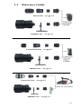
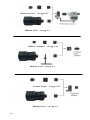
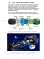
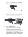
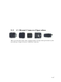
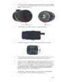
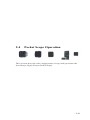
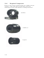
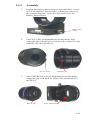
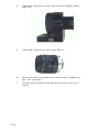
1
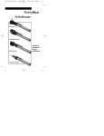
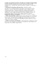
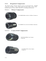
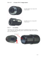
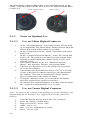
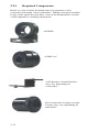
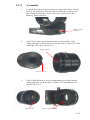
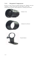
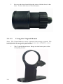
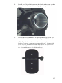
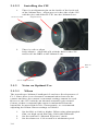
OPERATING MANUAL
ASTROSCOPE
NIGHT VISION
Export limitations: Because the AstroScope 9350 modules utilize
state-of-the-art image intensifier technology, it is unlawful to carry
these devices out of the country or to export them without an
approved U.S. State Department export license.
WARNING: TO REDUCE RISK OF
FIRE, ELECTRIC SHOCK OR DAMAGE, DO NOT
EXPOSE THIS PRODUCT TO CONTINUOUS RAIN
OR MOISTURE.
TO REDUCE RISK OF SHOCK AND TO REDUCE
ANNOYING INTERFERENCE, USE ONLY
RECOMMENDED ACCESSORIES.
CAUTION: DO NOT REMOVE THE
COVER. THERE ARE NO USER SERVICEABLE
PARTS INSIDE. REFER SERVICING TO
QUALIFIED SERVICE PERSONNEL.
EC PN 080526
REV C
February 2004
ii
TABLE OF CONTENT
1 INTRODUCTION TO ASTROSCOPE NIGHT VISION......................1-1
1.1 Purpose of This Manual ..................................................................1-1
1.1.1 How This Guide Is Organized..............................................1-1
1.2 Important Safeguards ......................................................................1-1
1.3 Reference Guide..............................................................................1-3
1.4 How Image Intensifiers Work.........................................................1-5
1.5 Evolution of Image Intensifiers ......................................................1-7
1.6 Benefits of AstroScope Night Vision .............................................1-7
2 ASTROSCOPE CONFIGURATION, SET-UP, AND OPERATION ...2-1
2.1 Removable-Lens Camera and Camcorder Operation.....................2-3
2.1.1 Required Components........................................................2-4
2.1.2 Assembly............................................................................2-5
2.1.3 Notes on Optimal Use........................................................2-6
2.2 Non-Removable-Lens Camcorder Operation ...............................2-11
2.2.1 Required Components......................................................2-12
2.2.2 Assembly..........................................................................2-13
2.2.3 Notes on Optimal Use......................................................2-14
2.3 C-Mount Camera Operation .........................................................2-17
2.3.1 Required Components......................................................2-18
2.3.2 Assembly..........................................................................2-18
2.4 Pocket Scope Operation................................................................2-21
2.4.1 Required Components......................................................2-22
2.4.2 Assembly..........................................................................2-23
3 ASTROSCOPE ACCESSORIES SET-UP AND OPERATION............3-1
3.1 200 mm Low-Light Telephoto Lens ...............................................3-3
3.1.1 Required Components........................................................3-4
3.1.2 Assembly............................................................................3-5
3.1.3 Notes on Optimal Use........................................................3-8
4 TROUBLESHOOTING GUIDE .............................................................4-1
5 MAINTENANCE ....................................................................................5-1
5.1 Key Operational Parameters ...........................................................5-1
5.1.1 Power: ................................................................................5-1
5.1.2 Environmental....................................................................5-1
5.2 Cleaning ......................................................................................5-1
6 WARRANTY ..........................................................................................6-1
6.1 HOW TO RETURN PRODUCTS FOR WARRANTY REPAIR .6-1
6.2 HOW TO RETURN PRODUCTS FOR “OUT OF WARRANTY”
REPAIR
......................................................................................6-2
7 CONTACT SHEET FOR REPAIRS AND SERVICE ...........................7-1
iii
1
INTRODUCTION TO
ASTROSCOPE NIGHT
VISION
1.1
Purpose of This Manual
This manual provides basic information and instructions for
operating the AstroScope 9350 products, as well as procedures for
troubleshooting. We suggest that you read this manual carefully
and retain the manual for future reference.
1.1.1
How This Guide Is Organized
Important Safeguards: Precautions to take before using the
equipment.
How Intensifiers Work and the Benefits of the 9350: Overview
of how Intensifiers operate, along with night vision advancements
and advantages of the 9350 units.
Set-Up and Operation: Description of how to prepare the 9350
unit for use, including camera and exposure settings.
Troubleshooting: Solutions to common problems.
Maintenance: Information on how to clean and store the 9350
units.
Product Specification: Information on current draw and
environmental specs.
Night Vision Terminology: A glossary of the basic terms used
when dealing with night vision.
Additional Information: Includes warranty and contact
information for repairs and service.
1.2
Important Safeguards
1)
Read Instructions - All safety and operating instructions
should be read before the product is operated. Keep the
instruction manual for future reference.
2)
Heed Warnings - Adhere to all warnings on the product and
in the operating instructions.
3)
Servicing - Do not dismantle or otherwise attempt to service
this product or any of the accessories yourself. Refer all
servicing to Electrophysics qualified service personnel.
Opening this product or its accessories will void the
warranty.
1-1
4)
Intensifier Protection – In order to assure long-life and high
sensitivity performance, do not use during daytime or bright
ambient conditions. Do not look at the sun or extremely
bright objects. Do not look at bright objects for long periods
of time as this may cause the intensifier tube to develop
insensitive areas.
5)
Accessories - Use only accessories and attachments
recommended by Electrophysics.
6)
Water and Moisture – These products are NOT waterproof.
They are only resistant to occasional small amounts of
moisture. Do not operate in continuous rain conditions or in
high moisture environments.
7)
Heat - The product should be situated away from heat sources
such as radiators, heat registers, stoves, or other sources of
heat.
8)
Power Sources - This product should be operated only from
the type of power source indicated here.
9)
Cleaning - Do not use unauthorized cleaning fluids and
materials. See Section 5.2 for proper cleaning instructions
10) Replacement Parts – Use only manufacturer-approved
replacement parts and accessories.
Damage Requiring Service – Refer servicing to
Electrophysics qualified service personnel under the
following conditions:
1)
If liquid has been spilled, or objects have fallen into the
product.
2)
If the unit has been exposed to rain or water and is now not
operating.
3)
If the product does not operate normally by following the
operating instructions.
4)
If the product has been dropped or damaged in any way.
5)
If the unit exhibits a distinct change in performance.
1-2
1.3
Reference Guide
Nikon Pair – see pg 2-3
200mm Lens – see pg 3-1
Canon EOS Pair – see pg 2-3
200mm Lens – see pg 3-1
Canon XL Pair – see pg 2-3
200mm Lens – see pg 3-1
1-3
Bracket Series – see pg 2-11
200mm Lens – see pg 3-1
BBA-C Adapter – see pg 2-17
200mm Lens – see pg 3-1
Pocket Scope – see pg 2-21
200mm Lens – see pg 3-1
1-4
1.4
How Image Intensifiers Work
Image intensifiers are predominant in night vision applications due
to their ability to amplify low-light scenes at night, making them
visible to the human eye and commercial cameras and camcorders.
Unlike thermal images, image intensifiers can be used to read
vehicle license tags and registration markings on boats and aircraft,
as well as to recognize faces, which can be entered as evidence in
criminal prosecutions.
The sequence to image formation in an image intensifier is as
follows: light is converted to electrons then converted back to light,
making intensifiers very simple devices featuring very high
resolution and extremely low power consumption.
Photons
Electrons
Photons
Unenhanced
Image
NVD Image
Photo
Cathode
Microchannel
Plate
Phosphor
Screen
A night vision system based on an image intensifier operates as
follows:
1. The very dim light reflected by scenes at night (lower than 0.1
lux) is focused by an objective lens onto a highly sensitive
1-5
photocathode. This dim light consists of energy in both the visible
and near-infrared portions of the electromagnetic spectrum.
2. When the light impinges on the photocathode (the light sensitive
portion of the image intensifier) electrons are emitted with
amplitude determined by the photocathode's spectral responsivity
and the amount of light energy. Because of the image intensifier's
internal electrical field, these electrons are accelerated toward the
microchannel plate assembly, the image intensifier's amplification
mechanism.
3. The microchannel plate is a glass plate with millions of tiny
closely-spaced channels bored through it. The plate is coated with a
special substance that produces secondary electron emission when
impinged by an electron. Due to the potential difference across the
plate, an incident electron enters a channel and frees other electrons
from the channel wall. These electrons are accelerated along the
channel in turn striking the channel surface again and again, giving
rise to more and more electrons. Eventually this cascade process
yields a cloud of several thousand electrons, which emerge from the
rear of the plate.
4. Electrons exiting the microchannel plate strike a phosphor that
emits light proportional to the amount of electrons hitting it. The
image is green because the selected phosphor glows green when
charged. The green color is selected because the human eye can
differentiate more shades of green than any other color.
5. Because the image is inverted, a fiber optic "twister" is used to
rotate the image 180°.
6. A special relay optic focuses the image properly to match the
image plane requirements of video and 35mm SLR cameras.
Image intensifiers exhibit several key features designed to optimize
their use, as follows:
Automatic Brightness Control (ABC): An electronic feature that
automatically reduces voltages to the MCP to keep the image
intensifier’s brightness within optimal limits and protect the image
intensifier. The effect of this can be seen when rapidly changing
from low-light to high-light conditions; the image gets brighter and
then after a momentary delay, suddenly dims to a constant level.
Bright-Source Protection (BSP): An electronic function that
reduces the voltage to the photocathode when the image intensifier
is exposed to bright light sources such as room lights or car lights.
It protects the image intensifier from damage and enhances its life.
Equivalent Background Illumination (EBI): This describes the
amount of light you see from the output of the image intensifier
when there is no light input. It increases with increasing
temperature. EBI is measured in lumens per square centimeters and
determines the light level, which equals the image intensifier’s
noise level. Below this light level, objects will be masked by EBI.
The lower value of EBI, the better.
1-6
1.5
Evolution of Image Intensifiers
The image intensifier tube has evolved substantially over the past
few decades. This evolution is described by different generations
(“Gen”) of technology as follows:
Gen 1 – These are the first so-called night-vision devices and were
introduced in the early 1960s and first fielded in Vietnam. These
devices utilized a multi-alkali S-25 photocathode having a spectral
response extending from visible to about 850nm. In order to have
sufficient sensitivity for use in night vision applications, three Gen
1 image intensifier tubes needed to be cascaded, each producing
some gain. The result, though highly sensitive, suffered from
significant edge distortion as well as poor life expectancy (less than
1000 hours).
Gen 2 – By the 1970s, the microchannel plate was introduced that
delivered high sensitivity imaging without the need to cascade three
stages. As a result, night vision pocketscopes and night vision
goggles emerged as viable products with improved operation life
(2000-4000 hours).
Gen 2+ – More recently, improved Gen 2 devices have been
developed (known as "SuperGen") that deliver improved sensitivity
and improved lifetime (10,000 hours).
Gen 3 – By the early 1990s, image intensifiers became available
with photocathodes made from gallium arsenide. This produced
significantly more sensitivity and an extended near-infrared spectral
responsivity range to 950nm.
Gen 3 Thin Film –Introduced in 2002, thin film image intensifiers
incorporate a new manufacturing technique, which have made it
possible to increase further the unit's sensitivity, improve signal-tonoise and contrast performance and reduce blooming due to
viewing bright sources.
1.6
Benefits of AstroScope Night Vision
The AstroScope Night Vision System is a modular system
incorporating a “common module” approach in which the image
intensifier is integrated into an assembly consisting of a front lens
adapter and a back body adapter. The AstroScope System delivers
several important benefits over other night vision systems. These
include:
• Optimized Performance: Because of the modular design and
the accessibility to the image intensifier, optical adapters and
interfaces can be designed so that each configuration delivers
optimized performance. This is due to the accessibility to the photo
cathode as well as the phosphor image output.
• Seamless Integration into Daylight Imaging Systems: The
AstroScope’s component interfaces are both electrical (where
electrical contacts connect components) and mechanical. This
results in a seamless integration with daylight imaging systems. As
1-7
a result, surveillance operatives that have been trained with daylight
imaging equipment may insert an optimally-configured night vision
module into the daylight lens/camera system and operate the
equipment in virtually the identical fashion at night as compared to
the day.
• Reduced Technology Obsolescence: Because of the
AstroScope’s modular design, this night vision system is never
obsolete. As new cameras are introduced, new adapters can be
designed that deliver optimal night-time imaging performance
without the need to purchase an additional image intensifier. In
addition, as new image intensifiers become available because of
technology improvements, these image intensifiers can be
purchased to deliver even higher performance with the existing
adapters and camera equipment.
• Fully Accessorized: Adapters have been designed for optimized
use on Canon EOS and Nikon digital and SLR cameras, as well as a
wide range of Camcorders including the Canon XL1S, Sony PC110, 120, and 330, C-mount CCD/CMOS cameras and as a viewer
using an eye piece adapter.
• Future Accessory Availability: Electrophysics continues to lead
the way in developing new and useful components and adapters for
night-time surveillance applications.
1-8
2
ASTROSCOPE
CONFIGURATION, SET-UP,
AND OPERATION
2-1
2-2
2.1
Removable-Lens Camera and
Camcorder Operation
This section describes the configuration set-up and operation of
AstroScope Night Vision on removable-lens cameras and
camcorders, such as Nikon SLF/Digital Cameras, Canon EOS type
SLR/Digital Cameras and Canon XL Camcorders.
2-3
2.1.1
Required Components
The Nikon, EOS, and XL adapters pairs are pictured below. Handle
each part carefully. If any of the optics becomes dirty, refer to the
Maintenance section of this manual for cleaning instructions.
2.1.1.1
Nikon Components
9350NIK BBA side for Nikon Cameras.
9350NIK FLA side for Nikon Cameras.
2.1.1.2
Canon EOS Components
9350EOS BBA for Canon
Cameras
9350EOS FLA for Canon
Cameras
2-4
2.1.1.3
Canon XL Components
9350XL BBA for Canon XL
Camcorders
9350XL FLA for Canon XL
Camcorders
2.1.2
Assembly
The Front Lens Adapter (FLA) has an alignment pin on the inside
wall. Align the pin with the groove on the side of the CIU and slide
the CIU into the FLA.
Alignment Pin
Groove in CIU
2-5
The Back Body Adapter (BBA) has a silver alignment pin on the
inside. Align this pin with the hole in the CIU and thread the BBA
to the FLA.
Silver Alignment Pin
Hole in CIU
2.1.3
2.1.3.1
1.
2.
3.
4.
5.
6.
7.
8.
2.1.3.2
Notes on Optimal Use
Use on Nikon Digital Cameras
In the “Shooting Menu,” select and set the ISO to 1600
or a comparable fast ISO setting. Some cameras limit the
ISO to 800 while others allow up to 6400.
In the “Custom Functions” menu, select ISO Auto and
turn it off.
In the “Custom Functions Menu”, select AF Assist and
turn it off. This will prevent the focus assist light from
turning on and helping the camera focus or give your
position away.
The camera should be set in a “Manual Exposure
Mode”, not Aperture, Shutter, or Program mode.
The lens iris should be set to its widest open position
(f/1.4 as an example).
The shutter speed should start off at 1/30th of a second,
as this is the slowest shutter speed you can hand-hold
the camera. This can be adjusted to a faster shutter
speed if directed by the camera’s meter.
Using the camera’s meter, you can adjust the shutter
speed as required for a perfect exposure.
In extreme low-light conditions, you may want to adjust
the “exposure compensation” to a +2 stop.
Use on Canon Digital Cameras
Note: To prevent the camera from making any noise, flashing, and
illuminating the LCD panel, it is suggested to set the camera as
follows:
1.
2.
3.
4.
5.
6.
2-6
Turn the dial on the top left to the “M” position.
Press the “Menu” button once.
Red-eye On/Off – Set to “Off”.
AEB – Set to “0”.
ISO – Set to a minimum of “1000”.
Beep – Set to “Off”.
7.
8.
9.
10.
11.
Review – Set to “Off”.
File numbering – Set to “Continuous”.
Video system – Set to “NTSC”.
Custom Function (C.Fn) –
a. Press the center button. On the Canon D30,
scroll down to number 5 and press the button
again. Set to “Off” and press the button a third
time. Press the “Menu” button twice and the
display will turn off.
b. Night time exposure. On the Canon D60, scroll
to number 5 and press the button again. Set to 1.
It will not emit/Fire. Press the button a third time,
press the “Menu” button twice, and the display will
turn off.
To increase the ISO setting on the D60, with the camera
in “M” manual mode, press and hold the “*” button on
the upper right back part of the camera and turn the
thumb wheel located just behind the shutter button until
the bar is under the 2+. The ISO is now increased from
1000 to 4000.
Looking through the viewfinder, exposure information will be
displayed on the bottom. The left number is the shutter speed. To
the right of the shutter speed is the aperture. The three dots can be
disregarded. “-1 2 T 1 2+” is the exposure guide.
1.
2.
3.
4.
There is a wheel just behind the shutter release button.
Turn the wheel until the shutter speed displayed in the
viewfinder reads “30.”
On the back of the camera above the large thumb wheel
is another On/Off switch. Turn it to “On.” The large
thumb wheel will now change the aperture. Looking
through the viewfinder, adjust the wheel until the 2.8 or
the lowest number appears next to the shutter speed.
To the far right of that display is a “-1 2 T 1 2+.”
The best exposure is when the moving line is directly
under the “T.” To the left of the center arrow will
produce a dark image and to the right will produce a
bright image.
If there is too much light, use the wheel on the top of the
camera to increase the shutter speed (60, 90, 125, 180…)
Shutter Speed Note: Never use a shutter speed slower than
1/30 sec. or the image will become blurred.
2.1.3.3
1.
2.
3.
4.
5.
6.
7.
Use on Canon XL Camcorders
Secure the BBA side of the 9350XL to the Camcorder.
Secure the Lens to the FLA side of the 9350XL.
Turn the Camcorder on to the “M”, Manual mode.
Turn the Neutral Density filter on the lens “Off”.
Set the white balance in the “auto” position.
Adjust the aperture (iris) to f/1.6. As you zoom, the
aperture will move to f/2.6. You will have to readjust
the iris when you zoom out.
Adjust the shutter speed * to either 1/30 or 1/60 second.
2-7
8.
Gain: The XL-1 has a maximum gain of +12db and the
XL-1S has a maximum of +30db. As you increase the
gain, the image quality decreases. Try and limit the gain
to no more than +6db on the XL-1 and between 12-18db
on the XL-1S.
*See the Canon operating instructions.
2.1.3.3.1
EOS to XL Adapter
You can use the full line of Canon EOS lenses on the Canon XL-1S
Camcorder with the use of the Canon XL-EOS Adapter. There is a
magnification increase of 7.2x the focal length of the EOS lens (for
example a 400mm EOS lens translates to a 2880mm lens on the
XL-1S). You can use the XL-EOS Adapter with the AstroScope
night vision system ONLY with the 9350EOS-Pair. The 9350XLPair will not function in conjunction with the XL-EOS Adapter.
Canon XL-EOS Adapter
2.1.3.4
1.
2.
3.
4.
5.
2-8
Use on Film Cameras
Select a fast film with an ISO of at least 1000. The user
can decide on black & white or color film, as both will
provide excellent imaging. Black & white films have
greater latitude and will produce a higher contrast image.
Color films will provide the green images.
Turn the “auto-focus” switch to manual focus. The autofocus cameras available today use a variance of contrast
to attain sharp focus. At low-light levels contrast is not
typically high enough for the auto-focus to operate
effectively, therefore manual focus generally is faster
and more accurate.
The camera should be set in the “manual exposure
mode”.
Adjust the lens to its widest aperture (e.g. f/1.4).
Adjust the shutter speed to 1/30 second as this is the
minimum speed you can hand-hold the camera.
6.
Using the camera’s metering system, adjust the shutter
speed to attain a correct exposure.
Note: All EOS and only Nikon Auto-S brand lenses may auto-focus
with the AstroScope if there is enough light.
2-9
2-10
2.2
Non-Removable-Lens Camcorder
Operation
This section describes the configuration set-up and operation of
AstroScope Night Vision on non-removable lens camcorders.
2-11
2.2.1
Required Components
Below is a list of items included when you purchase a nonremovable lens night vision camcorder. Handle each part carefully.
If any of the optics become dirty, refer to the Maintenance section
of this manual for cleaning instructions.
9350EPA
9350FLA-C
9350 Bracket (Actual Bracket
may vary depending on
camcorder)
9350 Camcorder Coupler (Actual
Coupler may vary depending on
camcorder)
2-12
2.2.2
1.
Assembly
Loosen the battery door release to open the door. Insert
two AAA batteries into the EPA oriented as shown on
the internal diagram. Close the door and secure the
Battery Door release.
Battery Door
release
2.
The FLA-C has an alignment pin on the inside wall.
Align the pin with the groove on the side of the CIU and
slide the CIU into the FLA-C.
Alignment Pin
Groove in CIU
3.
The 9350EPA has a silver alignment pin on the inside.
Align this pin with the hole in the CIU and thread it to
the 9350FLA-C
Hole in CIU
Silver Alignment Pin
2-13
4.
Thread the 9350 Camcorder Coupler to the back of the
9350EPA. Loosely thread the 9350EPA to the Bracket
using the threaded screw on the platform, so that the
EPA can slide back and forth.
5.
Loosely thread the Camcorder to the Bracket using the
other threaded screw.
6.
Slide the EPA back and thread the Camcorder Coupler
to the front of the Camcorder. Tighten both threaded
screws to secure the EPA and the Camcorder.
7.
Secure the Objective Lens to the FLA-C.
2.2.3
1.
2.
3.
4.
2-14
Notes on Optimal Use
To activate the unit, turn the power switch on the
9350EPA to the “On” position.
Turn the camcorder on.
Using the camcorder’s zoom feature, zoom to the
appropriate position so that the unit does not vignette,
resulting in a crisp full frame image without a circle. Do
not zoom past that point or the image quality will be
reduced.
To set the focus, turn the camera to manual focus. Look
at a subject approximately 15 feet (5 meters) away and
set the objective lens to that distance. Turn the camera
lens ring until the object is in crisp, sharp focus. Only
focus with the objective lens for crisp and sharp images.
NOTE: It is always best to select an objective lens that
produces the desired magnification. Zooming with the
camcorder objective lens will result in grainy, low contrast
images.
2-15
2-16
2.3
C-Mount Camera Operation
This section describes the configuration set-up and operation of the
AstroScope Night Vision C-Mount Cameras.
2-17
2.3.1
Required Components
The adapter pair for C-Mount Cameras is pictured below. Handle
each part carefully. If any of the optics becomes dirty, refer to the
Maintenance section of this manual for cleaning instructions.
9350BBA-C - The rear
module consisting of a 1” CMount thread, detachable
power cable and plug cap.
9350FLA-C - This is the CMount device into which the
objective lens is threaded to.
2.3.2
1.
Assembly
The FLA-C has an alignment pin on the inside wall.
Align the pin with the groove on the side of the CIU and
slide the CIU into the FLA-C.
Groove in CIU
2-18
Alignment Pin
2.
There is a silver alignment pin on the inside of the BBAC. Align this pin with the hole in the CIU and thread the
BBA-C to the FLA-C.
Silver Alignment Pin
Hole in CIU
3.
Attach the assembly to your c-mount camera.
4.
Attach an objective lens to the front of the assembly.
5.
Power the unit through the cable provided with 3 to 15
volts DC. The wire with the white stripe is positive.
6.
Set the focus on the objective lens to a subject 15 feet (5
meters) away. While looking at a monitor, loosen the
back focus lens locking screw to adjust the white plastic
focus wheel on the BBA-C housing until the best image
is obtained. This operation may need to be repeated to
get the best image. Re-tighten the lens locking screw
after satisfactory focus is obtained
7.
Thereafter, only the objective lens needs refocusing to
accommodate objects at different distances.
2-19
8.
If desired, attach the plug protective cap to prevent
inadvertent removal of the power plug from the unit.
9.
If you wish to reorient the 9350BBA-C with the tripod
mount at the bottom and the focus wheel on top, simply
loosen knurled thumb screw located at the back side of
the chassis and rotate the 9350 assembly with respect to
video camera to the desired position.
Locking Screw
Focus
Wheel
Push to remove
Shown without plug cap
2-20
2.4
Pocket Scope Operation
This section describes the configuration set-up and operation the
AstroScope Night Vision Pocket Scope.
2-21
2.4.1
Required Components
Below is a list of items included with the unit. Handle each part
carefully. If any of the optics becomes dirty, refer to the
Maintenance section of this manual for cleaning instructions.
9350EPA
9350FLA-C
Eyepiece
2-22
2.4.2
1.
Assembly
Loosen the battery door release to open the door. Insert
two AAA batteries into the EPA, oriented as shown on
the internal diagram. Close the door and secure the
Battery Door release.
Battery Door
release
2.
The FLA-C has an alignment pin on the inside wall.
Align the pin with the groove on the side of the CIU and
slide the CIU into the FLA-C.
Groove in CIU
3.
Alignment Pin
The 9350EPA has a silver alignment pin on the inside.
Align this pin with the hole in the CIU and thread it to
the FLA-C
Hole in CIU
Silver Alignment Pin
2-23
2-24
4.
Thread the Eyepiece to the back of the 9350EPA about
half way.
5.
Thread the Objective Lens to the FLA-C.
6.
Power the unit by turning the switch on the 9350EPA to
the “On” position.
7.
Set the lens at infinity and adjust the eyepiece for your
vision.
2-25
3
ASTROSCOPE ACCESSORIES
SET-UP AND OPERATION
3-1
3-2
3.1
200 mm Low-Light Telephoto Lens
3-3
3.1.1
Required Components
Below is a list of items included with the unit. Handle each part
carefully. If any of the optics become dirty, refer to the
Maintenance section of this manual for cleaning instructions.
200mm Lens
200mm Lens Hood
Tripod Mount
3-4
9350BBA EOS-N - * Supplied
only when the EOS model is
ordered.
3.1.2
Assembly
1.
The 200mm Catadioptric Lens is shipped with the lens
hood in the stowed position. Note: The hood has a
bayonet design, which allows you to remove it and
reverse it, so that the lens can be stored in a compact
form.
2.
To remove the hood, twist counter clockwise to unlock.
Slide hood off to remove.
3-5
3.
3.1.2.1
Reverse the hood and align the pins with the slots in the
lens. Twist clockwise to lock in place.
Using the Tripod Mount
Note: The Tripod Mount is only required when using a tripod. The
tripod mount is not used on units that include the 9350EPA, which
already have an integral tripod mount.
1.
3-6
The Tripod Mount has a flange on the inner part of the
Clamping mount.
2.
Install the Tripod Mount onto the back of the lens so that
it touches the flange. Secure by tightening the knob
screw.
3.
Secure the Tripod Mount to the tripod using one of the
three holes on the bottom until the system is balanced.
*The Tripod Mount base can be reversed if necessary to
balance a heavy camera system as follows: Remove the
three screws from the bottom and rotate the base 180°.
Secure the three screws back to the base and re-secure
the Tripod Mount to the 200mm Lens.
3-7
3.1.2.2
1.
Installing the CIU
There is an alignment pin on the inside of the back end
of the 200mm lens. Align groove in the side of the CIU
with the pin, and slide the CIU into the 200mm Lens.
Groove in CIU
2.
Alignment Pin
There is a silver alignment pin on the inside of the back
body adapter. Align this pin with the hole in the CIU
and secure the BBA to the 200mm Lens.
Hole in
CIU
Silver Alignment Pin
3.1.3
3.1.3.1
Notes on Optimal Use
Nikon
The AstroScope 200mm Catadioptric Lens has a fixed aperture of
F1.3. Since there is no electronic communication between the
camera and lens, the camera’s automatic settings cannot be used.
However, the CIU includes an internal automatic gain control
feature so that a constant light output is maintained from the
intensifier for most light levels. Consequently, we recommend
adjusting the Nikon camera settings as follows:
1.
2.
3.
3-8
Set the ISO to 1000 or higher. When using photographic
film, use high speed film only, ISO1000 minimum
Set the camera to “Manual Exposure” mode.
Set the shutter to 1/30 second as a minimum speed.
4.
3.1.3.2
Focus the objective lens as needed to optimize the image
sharpness.
Canon EOS
The AstroScope 200mm Catadioptric lens has no aperture. It is
permanently fixed at f/1.3. Since the camera has no electronic
communication with this lens, you must manually set the camera’s
electronics to f/1.8 to attain correct exposure metering.
1.
2.
3.
4.
5.
6.
7.
3.1.3.3
1.
2.
3.1.3.4
Install the 200mm Catadioptric Lens with EOS-N onto
the camera.
Set the ISO to 1000 or higher.
Set the camera to “Manual Exposure” mode.
Set the aperture to f/1.8.
Set the shutter to 1/30 as a minimum speed.
Use the camera’s metering to attain the correct exposure.
Focus the lens as needed.
9350 Bracket Series
Install the 200mm Catadioptric lens directly onto the
EPA along with the CIU.
Focus the lens as needed.
Canon XL-1S
The Canon XL-1S camcorder can use the 200mm Catadioptric lens.
The EOS-N adapter is required along with the Canon XL-EOS
Adapter. The AstroScope XL pair is not used.
1.
2.
3.
4.
5.
6.
7.
8.
3.1.3.5
1.
2.
3.1.3.6
1.
2.
3.
Remove the Canon 16x zoom lens from the camcorder.
Install the Canon XL-EOS adapter on to the camcorder.
Install the EOS-N adapter on to the 200mm Lens along
with a CIU.
Secure the Lens and EOS-N to the XL-EOS adapter.
Set the camcorder to “Manual Exposure” mode.
Set the aperture to f/1.6.
Set the shutter speed to 1/30 second.
Focus the Lens as needed.
9350BBA-C Relay Lens Adapter
Install the 200mm Catadioptric Lens directly onto the
BBA-C along with a CIU.
Focus the lens as needed.
9350 Pocket Scope
Install the 200mm Catadioptric Lens directly onto the
EPA along with a CIU.
Turn the EPA on.
Focus the lens as needed.
3-9
4
TROUBLESHOOTING GUIDE
Symptom
Vignetted
Images
Image is out
of Focus
Image is too
Dark
Auto Focus
Not
Operating
Suggested Remedy
Using 35mm Nikon or Canon film cameras
it is normal for some vignetting to occur on
the left and right side of the image. Using
Nikon or Canon Digital cameras having a
sensor size of 5 Meg or larger can expect
some vignetting. Smaller sensors will
produce full frame imaging. Using Sony
and other non-removable lens cameras will
experience a vignetted image when the
camcorder zoom is at its widest position.
Zoom the camera until the image fills the
screen.
Using SLR type camera, focus normally
using the cameras lenses. Using Sony and
other non-removable lens camcorders
require the camera to be set in the manual
focus mode. Set the objective lens at a
known distance (5 meters) and turn the
camera lens ring until the image is sharp.
You do NOT need to adjust the camera
focus ring again. Focus only with the
objective lens.
It is important to understand that all night
vision devices amplify the available light. If
the ambient lighting conditions are very
low, it may be difficult to obtain a
satisfactory shutter speed to hand hold the
camera. Make sure the lens aperture is set
to its widest position (ex. F/1.4). In
conditions where the camera wants to shoot
at slower than 1/30 second you should
check the ISO setting. Film cameras require
a film with at least and ISO of 1000 and
digital camera require a minimum ISO of
800. You should increase the ISO on digital
cameras when needed to shoot at 1/30
second.
The auto-focus systems on most cameras
use a variance of contrast to focus. In lowlight conditions, the contrast level is very
low and the auto-focus systems may not
operate efficiently. On Nikon camera only,
the Auto-S lenses may auto-focus, nonAuto-S lenses will not auto-focus under any
condition. Canon EOS lenses may autofocus and the Canon XL 16X lens will autofocus. It is generally faster to manually
focus these cameras.
4-1
No
Information
in the
Viewfinder
Flashing “No
Lens” on the
Canon XL
Camcorder
No Power
Using
9350BRAC
Adapters
No Power
Using the
Pocket Scope
adapter
No Power
Using the
9350BBA-C
adapter
Problems
Using the
200mm
Catadioptric
Lens on a
Canon EOS
Camera
Non-uniform
Image
Dark Spots in
Image
4-2
Nikon cameras operated in the manual mode
only, will provide accurate exposure
information. Canon EOS camera operated
in the manual mode will provide accurate
exposure information. Nikon cameras using
the 200mm Electrophysics lens will provide
no information in the viewfinder. Canon
XL camcorders provide complete
information in the viewfinder regardless of
the operating mode.
Check to make sure the 16x lens is securely
attached to the 9350FLA, the 9350BBA is
securely attached to the camcorder and a
CIU is properly installed inside the adapter
pair.
The 9350EPS requires two AAA batteries to
power the CIU. If the batteries are dead,
you will not see the green image in the
viewfinder. The camcorder must be turned
on as well.
The 9350EPA requires two AAA batteries
to power the CIU. If the batteries are dead,
you will not see the green image in the
eyepiece.
The 9350BBA-C requires a power source of
3-12 volts to operate. You will not see the
green image if the power connection is not
made.
You must use the special EOS-N Back
Body Adapter when using a Canon EOS
camera. Set the camera to f/1.8 to interface
with the lens. The standard EOS Back
Body Adapter will NOT operate with this
lens.
Sometimes an intensifier tub exhibits a faint
hexagonal pattern (honeycomb). This is a
result of the manufacturing process.
Note: Do not be concerned if you see this
feature. It is an inherent characteristic
found in light amplification night vision
systems that incorporate a microchannel
plate in the intensifier.
A few black spots throughout the image
area are also inherent characteristics of all
night vision technology. These spots will
remain constant and should not increase in
size or number.
5
5.1
5.1.1
MAINTENANCE
Key Operational Parameters
Power:
<300mw (<50mA typical)
5.1.2
Environmental
Operating Temperature: -20° to 50 °C
Storage Temperature: -40° to 80°C
Water Resistance: Splash proof
Operating Humidity: 0-95%
5.2
Cleaning
Non-optical surfaces: The non-optical surfaces of the lens can be
cleaned with water, mild detergents, and a soft cloth.
Optical Surfaces: The optical surfaces of the lens should only be
cleaned when visible dirty. Care should be taken to avoid touching
the exposed lens faces. Skin acid left behind with fingerprints can
be damaging to coatings and lens substrates. First use a jet of air or
blow across the surface to remove any sand or abrasive particles
before cleaning. If oil, water spots, or fingerprints form on the
optical surfaces, clean as soon as possible using a soft cotton cloth
and mild neutral soap diluted with lukewarm distilled water (1 part
soap to 100 parts water), followed by reagent grade isopropyl
alcohol or acetone swab. Dust can be removed gently using alcohol
or acetone swab.
Note: Avoid swabs that incorporate plastic stems, as some plastics
will dissolve in alcohol or acetone.
5-1
6
WARRANTY
1.
2.
3.
4.
5.
6.
7.
6.1
Electrophysics warrants that these products to be free
from defects in material and workmanship. Any
warranty described herein shall extend to the first
ultimate user only for a period of one year from the date
of shipment from our factory.
Electrophysics' obligation under this warranty shall be
limited to furnishing a replacement for, or at our option,
repairing any part which, to our satisfaction, proves
defective, provided such part is returned to the
Electrophysics service facilities in New Jersey, freight
paid. No product may be returned without prior
Electrophysics approval (see below).
Electrophysics shall not be responsible for installation
costs. In no event will any claim for labor in removing
or replacing defective parts or for incidental or
consequential damages be allowed.
No warranty is made on products that have not been
installed, operated or maintained in accordance with
these instructions, or which have been subjected to
misuse, abuse, accident or alteration or to improper or
negligent use, maintenance, storage, transportation or
handling.
Products not manufactured by Electrophysics which are
sold by Electrophysics are covered exclusively by the
original manufacturer's warranty and Electrophysics
may, at its option, assign to Buyer its warranty claims
against the original manufacturer of defective products
in full settlement of Buyer's possible claims against
Electrophysics with regard to such products.
Where Buyer is a distributor, financing company or
similar entity acting for or on behalf of the initial user of
the equipment, the warranty is transferable to the initial
user only. In all other cases, the warranty is limited to
the Buyer and is not transferable unless agreed to in
writing by Electrophysics.
The Warranty contained herein is exclusive and
expressly in lieu of all other warranties, written, oral,
implied or statutory, including but not limited to
expressed or implied warranties of merchantability or of
fitness. In addition, Electrophysics shall not be liable for
any loss, damage or injury of any nature, whether direct,
indirect or consequential, in connection with or resulting
from use of the products.
HOW TO RETURN PRODUCTS
FOR WARRANTY REPAIR
1.
2.
3.
Refer to the contact information for repairs and service.
A Return Authorization (RA) number will be assigned
by the service department. This number must be marked
clearly on the outside of the package being returned.
Service department will provide a shipping address.
6-1
4.
6.2
The following information must be included on the
packing slip:
A. Reason for return
B. Date and place of purchase
C. Installation date
D. Returned unit serial number
E. Description of problem
F. Return Authorization Number
HOW TO RETURN PRODUCTS
FOR “OUT OF WARRANTY”
REPAIR
Following expiration of the warranty period, the owner is
financially obligated to pay for any repairs which are required. The
owner may either return their product to their dealer and the dealer
will take care of it, or, they may work with Electrophysics directly.
If you choose to deal directly with Electrophysics, you may contact
us through the phone number and address provided on the contact
sheet at the end of this booklet.
You are required to provide the following information:
1)
Model and serial number of product
2)
Your shipping address
3)
Your billing address (if different)
4)
Your fax and telephone numbers
5)
Description of the failure
6)
Name of the point of contact
You will be asked for payment of an evaluation fee prior to
beginning work. Following evaluation, when the extent of the
repairs is known, someone will contact you and estimate the total
cost of the repair. If you choose not to have the repair completed,
you will still be liable for the evaluation fee. If you choose to
authorize the repair, the equipment will be repaired and returned
following receipt of payment.
6-2
7
CONTACT SHEET FOR
REPAIRS AND SERVICE
Electrophysics Corporation
373 Route 46 West
Fairfield, New Jersey 07004
USA
Toll Free Telephone: (800) 759-9577
Telephone: (973) 882-0211
Fax: (973) 882-0997
E-mail: [email protected]
7-1


![English-T series-NOVA-User manual-F [兼容模式]](http://vs1.manualzilla.com/store/data/005791006_1-acba31ea472695c25db426bea2198a0f-150x150.png)