1
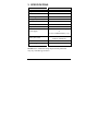
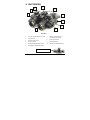
Operation Manual NIGHT VISION GOGGLES NVS 15 105 Sparks Ave., Toronto, ON, M2H 2S5, Canada IMPORTANT INFORMATION Read prior to activation. You have purchased a sophisticated electronic device. To operate it properly, please read this manual carefully. Ignoring operation procedures described in this manual will void your warranty. NEVER disassemble the unit. This device contains a source of high voltage, which may be hazardous to your health. NEVER expose objective lens of an active unit to bright light, including daylight. In the daytime objective lens must be covered by cap. A tiny hole in lens cap provides enough light for daytime testing. NEVER aim an active unit at intense light sources, such as lights, headlamps, campfires, the Moon, etc. NEVER reverse the polarity of a battery. NEVER connect the unit to the external power supplies. ALWAYS remove battery when not in use for a long period. ALWAYS keep the objective lenses covered when not in use. ALWAYS store the unit in a warm dry place. ii Precautions NVS 15 is a sophisticated precise optical instrument equipped with electronics. It should be handled with due care: Do not touch the optical surfaces other than for cleaning. Doing so may damage the anti-reflection coating. Clean optical surfaces with professional lens cleaning supplies. Use only a soft clean cloth to clean the exterior of the device. Keep the unit away from sources of heat, such as heating appliances, sunlight or central heating. Switch off the unit and remove the battery during the extended periods of non-operation. Do not apply an excessive force or pressure to the lens assembly, movable parts and thread connections. Small dark and/or light spots may be seen in the field of view due to considerable optical magnification of the eyepiece. This does not affect the operational capabilities of the device. iii TABLE OF CONTENTS 1. 2. 3. 4. 5. OVERVIEW .................................................................... 3 DELIVERY SET .............................................................. 5 2.1 Optional accessories.............................................. 5 SPECIFICATIONS .......................................................... 6 UNIT DESIGN................................................................. 7 OPERATION INSTRUCTIONS ..................................... 8 5.1 Installing battery ................................................... 8 5.2 Switching the unit on ............................................ 8 5.3 Switching the unit off ............................................ 9 5.4 Adjusting to individual vision ............................... 9 5.5 Focusing .............................................................. 10 5.6 Manual gain adjustment ...................................... 10 5.7 Auto shut OFF at bright light .............................. 11 5.8 Using the unit with headgear or helmet .............. 11 5.9 Swinging head mounted unit for unobstructed view12 5.10 Using IR illuminator ........................................... 12 5.11 Installation of add-on lenses................................ 13 5.12 Demist shield and sacrificial window ................. 13 5.13 Using the camera / video adapter ........................ 14 5.14 Using the helmet mount ...................................... 14 5.15 Mounting on a rifle ............................................. 16 5.16 Using with a daytime riflescope .......................... 17 1 6. 7. 8. 9. 5.17 Binocular configuration ...................................... 18 TROUBLESHOOTING ................................................. 19 6.1 No green light through eyepieces ........................ 19 6.2 Image is unclear .................................................. 19 6.3 Image flashes ...................................................... 19 6.4 Condensation accumulates on the parts .............. 19 6.5 Visibility decreased or disappeared..................... 19 WARRANTY................................................................. 20 CUSTOMER SUPPORT ............................................... 21 ACCEPTANCE CERTIFICATE ................................... 23 2 1. OVERVIEW NVS 15 (the unit) is an optoelectronic monocular, intended for observation of objects and orientation at night or under dark conditions. The unit is equipped with a generation 3 image intensifier tube, which amplifies low light, such as moonlight, starlight or man-made light. An add-on lens can be attached to the unit to increase magnification. Two units are combined to form a binocular configuration. NVS 15 goggles in binocular configuration can be mounted on a helmet (headgear). Some typical activities where NVS 15 can be useful: Law enforcement Wildlife observation Security Search and rescue Hunting Dark room photography (connected to a camera) Features Swing arm mechanism provides for unobstructed vision when the unit is mounted on headgear or helmet Built-in infrared illuminator enables observation in total darkness (i.e. basement, cave or dark room); Optional helmet mount allows combatant operations 3 Optional weapon mount allows night shooting or also be used in conjunction with halosight Soft rubber eyecup makes viewing comfortable Unit can be connected to photo or video camera Please read all the instructions carefully before using it. Manufacturer reserves the right to introduce minor design changes without notice. 4 2. DELIVERY SET Standard* Delivery Set includes: Quantity 1 1 1 2 1 2 1 2 1 NVS 15 NVS bridge Headgear set Lens cap / Battery cover Manual Lens cleaning kit Carrying bag (soft) AA Battery Warranty card 2.1 Optional accessories US clip mount Demist shield Sacrificial window 3x add-on lens 5x add-on lens Weapon mount Hard case Lens brush Camera / video adapter Helmet mount *Exact Delivery Set is subject to the specific contract terms. 5 3. SPECIFICATIONS NVS 15 Magnification 1x Field of view 40 Focus range, m 0.25- Interpupillary distance,mm 58-72 Exit pupil diameter, mm 20 Eye relief, mm 25 Dioptric correction Power supply +5 … -6 3V CR-123 Lithium battery, 1 pc. or 1.5 V AA Alkaline battery, 1 pc. 20 hours with I/R 40 hours without I/R Battery life, hours Size, mm 118x120x69 Weight, goggles only, g 720 NOTE: Due to continuous design improvements parameters may vary from those given above. 6 4. UNIT DESIGN 6 5 8 3 2 10 7 9 4 1 FIGURE 1 7. Battery compartment cover with battery type adapter Eyepiece with eyecup 8. Quick release knobs NVS 15 housing 9. Dovetail platform 5. Standard Headgear/helmet mount 10. Manual gain adjustment knob 6. Interpupillary adjustment buttons 1. On / Off and IR illuminator switch 2. Objective lens 3. 4. NVS bridge with US Mount 7 5. OPERATION INSTRUCTIONS 5.1 Installing battery Unit is supplied with uninstalled battery. Prior to installing the battery, make sure the switch (1, Fig.1) is in the OFF position and the lens cap is on. The unit can operate on either AA Alkaline or CR-123 Lithium battery. Lithium battery durability is doubled against the service time of conventional battery and provides better performance at low temperatures. To install battery unscrew the battery compartment cover (6, Fig.1). When using CR-123 Lithium type battery, remove the battery type adapter. Observe the polarity indicated on the housing. Put the battery in and screw the battery cover back on. 5.2 Switching the unit on In the daytime put on the lens cap with the daylight filter prior to switching the unit on. To check if the unit is operational switch it ON (rotate switch (1, Fig.1)) and look through the eyepiece (3, Fig.1). You should see greenish-lit screen. If the screen is not lit check the battery. When the unit is ON user may see either one or two circular indicators through the eyepiece (Fig. 2). When inactive they are hardly noticeable. Bright yellow or flashing red spot indicates low battery voltage. For an uninterrupted operation keep a fresh battery ready and replace it on time. Bright red indicator reminds 8 the user that the IR illuminator is on (for more details on illuminator see 6.9). In the daytime with lens cap on it is normal to observe a fuzzy image. Switching on the night vision device in the daytime is intended for testing purposes only. The rotating switch has four positions: “Off”, “Auto”, “On”, “IR”. In Auto mode the goggles will FIGURE 2 switch off automatically when turned upright. This mode saves battery life IR illuminator indicator (red, and allows avoiding greenish left), Low battery indicator shadow on the face, which may (yellow, right) disclose the user. 5.3 Switching the unit off After you have finished using the device, turn it off by rotating switch (1, Fig.1) to OFF position. Put a protective lens cap on the lens. Remove the battery from the battery compartment to avoid any damage of the device in case of electrolyte leakage. 5.4 Adjusting to individual vision Turn on the device. Direct the device at an object placed within 8-15m from the viewer. Obtain the sharpest image possible on the eyepiece screen by focusing the eyepiece lens and then the objective lens (2, Fig. 1). 9 5.5 Focusing To obtain a sharp image at some other distances adjust the lens focus (3, Fig. 1) leaving the eyepiece setting intact. You should be able to obtain a sharp image for distances from 2-10m to infinity. If you wear eyeglasses or NBC protective mask, you may like to fold the rubber eyecup. 5.6 Manual gain adjustment NVS 15 goggles is equipped with the manual gain adjustment handle. The light gain of the Image Intensifier Tube is set to the level, at which it allows viewing in the darkest conditions. While outside illumination increases at dusk, dawn, full moon or in the environment with artificial lights, the tube enters the Automatic Brightness Control (ABC) mode that automatically decreases gain to keep the screen brightness on the same level thus protecting both the tube and the observer’s vision. It leads to situation when the contrast of the image (relation between the brightest and darkest patterns on the screen) becomes lower, and detection/recognition ranges become shorter. In order to prevent deterioration of device performance under higher illumination the user can rotate the manual brightness control knob counter clockwise to restore full functionality. The brightness control can be adjusted in the range of 20-100% . 10 5.7 Auto shut OFF at bright light The NVS 15 goggles has a built-in high light sensor located near the IR illuminator (2, Fig. 1). This sensor shuts the goggles off after about 45 second exposure to light exceeding 10-1 lux. To reset the goggles switch it off and then back on as described in 6.3 and 6.2. High-light shut-off feature does not mean that the unit will react to occasional flashes or bright spots. It protects the tube against excessive light exposure only. 5.8 Using the unit with headgear or helmet The unit is supplied with headgear. Prior to using the headgear adjust its straps so that the headgear fits the head comfortably but firmly and does not slide off when you are moving. The unit is attached to the headgear using standard headgear/helmet mount already attached to the NVS bridge (5, Fig. 1). 1 To attach headgear to loosen the tightening screw (2, Fig. 3) on headgear, slide the standard mount on 2 the bridge onto the rail on the FIGURE 3 headgear/helmet mount, and then tighten the screw. To set comfortable eye-relief (the distance between your eye and the eyepiece), loosen tightening screw (8, Fig. 3) on the headgear and move the unit, then tighten the locking screw. 11 5.9 Swinging head mounted unit for unobstructed view When the head mounted unit is not in use you can raise it to clear the view without taking the headgear off by using the “flip/flop” feature. To swing the unit from the view press the button (1, Fig. 3) and raise the device until you hear a click. In “Auto” position of the switch, the goggles will turn off automatically. Reverse the operation to return the unit to working position. 5.10 Using IR illuminator In case of insufficient light when observing a close object turn on the IR illuminator by turning the switch (1, Fig.1). Red indicator visible through the eyepiece will warn you when the IR illuminator is on. Note: The IR illuminator is visible to anybody equipped with a night vision device and can disclose the user’s presence. 12 5.11 Installation of add-on lenses. Always make sure that the goggles is switched off when you put on or take off the add-on lens. FIGURE 4 NVS 15 Single unit with attached 3x lens Note: The following procedure is identical for 3x or 5x lenses (or any other add-on lenses). Turn off the goggles. Remove the lens cap. Press the lens firmly towards the eyepiece. Do not apply excessive pressure. Make sure that the lens is fixed well on the goggles. To return the goggles back to 1x magnification, pull off the lens. 5.12 Demist shield and sacrificial window Note: Demist Shield and Sacrificial Window are optional. Sacrificial window protects the objective lens from the abrasive influence of sand and dust in the night time. It should be put on the objective lens like an objective cap with the daylight filter. 13 Demist shield filter protects the eyepiece against fogging. To install it fold the eyecup to the very bottom to get the full access to the thread, and screw the filter gently onto the eyepiece. 5.13 Using the camera / video adapter Before using the (optional) adapters, remove the rubber eyepiece carefully. The adapter (Fig. 5) consists of 2 rings: a) Camera adapter is 52x0.75mm. It fits the filter lens thread of various cameras, e.g. Nikon. FIGURE 5 b) Video adapter is 37x0.75mm. It Camera / Video adapter fits Sony cameras and some others. If our adapter does not fit your camera obtain a proper step up / step down rings. 5.14 Using the helmet mount The unit can be equipped with an optional helmet mount. This mount can be customized to fit a wide range of existing helmet models. The mount is attached to a helmet with straps. 14 1 2 3 4 FIGURE 6. Helmet mount 1. Locking screw 3. Flip-flop adjusting screws 2. Flip/flop button 4. Mount binding screw The unit is fixed to the mount by the locking screw (1, Fig. 6). To adjust the position of the unit to your eye level use the screw (4, Fig. 6). To adjust the eye relief first loosen the locking screw (1, Fig.6) and set a comfortable distance between the eyes and the eyepiece; then tighten the locking screw back. You can fixate the unit in three predetermined positions: vertical, horizontal, and 15-20 degrees above horizontal. Although the relative angles between these positions cannot be changed, the starting point can be adjusted by screws (3, Fig.6). If you loosen them, you can rotate the flip-flop mechanism to find the suitable starting point. Tighten the screws (3, Fig.6) after the adjustment. 15 You can raise the unit for unobstructed view without taking the helmet off. To do so press (and hold) the button (2, Fig.6) and rotate the unit until you hear a click. All other operations with the unit mounted on a helmet are identical to those with the headgear. 5.15 Mounting on a rifle The unit can be mounted on a rifle with Picatinny mount adapter (MIL-STD-1913). The optical axle of the goggles coincides with the rifle’s Picatinny rail. FIGURE 7. NVS Unit with Picatinny adapter. Two types of weapon mount adapters are available – Fig.7 and Fig. 8. Either adapter enables mounting the unit to the Picatinny rail. The type shown on Fig. 7 has two screws with large grooved heads for convenient tightening. Note: Over tightening the screws may damage the thread. The ‘Quick Release’ model (Fig. 8) utilizes a latch with a spring and patented accu-torque screw. You can attach and detach your goggles within a few seconds. The accu-torque screw fixes the mount with predefined torque thus protecting the thread from accidental damage caused by over tightening. 16 The advantages of the ‘Quick Release’ mount are: Quick removal and installation of the device; Foolproof design; FIGURE 8 Quick Release adapter “Accu-torque” screw Latch with spring Increased reliability. 5.16 Using with a daytime riflescope Although the unit does not contain a reticle and thus cannot be used as a riflescope, being mounted on a daytime riflescope or red-dot sight, it enables aiming at night. In this configuration the objective lens of the unit is mounted on an eyepiece of the daytime scope with the help of an optional FIGURE 9. NVS Coupler. NVS Coupler 17 5.17 Binocular configuration Two units can be combined into dual channel goggles/binoculars with the help of an optional bridge. Optional lens can be attached to form a binocular 3x system. To form a double-unit system use the dovetail platform (10, Fig.1) located on both sides of the unit. These platforms are identical. The tightening screw (8, Fig. 1) locks goggles to the bridge. In this configuration the unit can be used in a goggle (mounted on a headgear) or handheld. Figure 10. Bridge FIGURE 11. Goggles configuration FIGURE 12. Binoculars configuration In the dual configuration the interpupillary distance can be adjusted between 58 and 72 mm right on a bridge. 18 6. TROUBLESHOOTING 6.1 No green light through eyepieces Check that the batteries are installed properly. Check the charge of the batteries. Replace them if they are weak. 6.2 Image is unclear Check if the lenses are foggy or dusty. Clean them if necessary. If the image is still unfocused – adjust the eyepieces; see 5.5 and 5.6 for details. 6.3 Image flashes Image may flash during the first two minutes after activation. It may continue flashing if exposed to bright light (even with the lens cap on!). 6.4 Condensation accumulates on the parts When the unit is brought from the cold into a warm environment internal condensation may appear. The unit has to be warmed up for up to two hours to regain full operational capacity. 6.5 Visibility decreased or disappeared Bright light sources (the Moon, projectors or headlights) may cause visibility to degrade or even completely disappear. Move the device away from the light source immediately. The image will be restored within two minutes. Adverse atmospheric conditions such as fog, haze or extremely dark environments decrease visibility. 19 7. WARRANTY NEWCON OPTIK warrants this product against defects in materials and workmanship for one year from the date of the original purchase. Longer warranty is available, subject to the terms of the specific sales contract. Should your Newcon product prove to be defective during this period, please deliver the product securely packaged in its original container or an equivalent, along with the proof of the original purchase date, to your Newcon Dealer. Newcon will repair (or, at its option, replace with the same or comparable model), the product or part thereof, which, on inspection by Newcon, is found to be defective in materials or workmanship. What This Warranty Does Not Cover: NEWCON is not responsible for warranty service should the product fail as a result of improper maintenance, misuse, abuse, improper installation, neglect, damage caused by disasters such as fire, flooding, lightning, improper power supply, or service other than by a NEWCON Authorized Service. Postage, insurance and shipping costs incurred while presenting your NEWCON product for warranty service are your responsibility. 20 8. CUSTOMER SUPPORT Should you experience any difficulties with your Newcon Optik product, consult this manual first. If the problem remains, contact our Customer Support Department at +1(416) 663-6963 or toll free at 1-877-368-6666 (North America only). Our operating hours are 9am-5pm, Monday - Friday, Eastern Standard Time. Under no circumstances should the equipment be sent to Newcon without authorisation from our technical support department. Newcon accepts no responsibility for unauthorized returns. To locate NEWCON Authorized Dealer call: +1(416) 663-6963 or fax: +1(416) 663-9065 Email: [email protected] Web: www.newcon-optik.com The defective products should be shipped to: From all countries: 105 Sparks Ave., Toronto, ON M2H 2S5, CANADA 21 This page was intentionally left blank 22 9. ACCEPTANCE CERTIFICATE Image Intensifier Tube #1 serial number: __________________ Image Intensifier Tube #2 serial number: __________________ Minimum Resolution, lp/mm Photocathode sensitivity, integral, A/lm Tube #1 Measured Tube #2 Measured 57 1800 Light amplification 50,000 Signal-to-noise ratio 23 Date of production:__________________________________ Quality Inspector: ___________________________________ 23 NIGHT VISION GOGGLES NVS 15 Unit #1 serial number: _________________________________ Unit #2 serial number: _________________________________ The unit complies with all technical specifications and has passed the inspection. Date of production: _________________________________ Quality Inspector: __________________________________ Quality Assurance Seal 24 R1.XT– 9.12 NEWCON OPTIK Printed in Canada