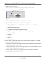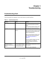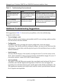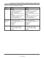
1
Managed Layer 2
Switches GSM7224 and
GSM7248 Hardware
Installation Guide
NETGEAR, Inc.
350 E. Plumeria Drive
Sant Jose, CA 95134 USA
202-10351-02
July 2009
© 2009 by NETGEAR, Inc. All rights reserved.
Technical Support
Please refer to the support information card that shipped with your product. When you register your product at
http://www.netgear.com/register, we can provide you with faster expert technical support and timely notices of product
and software upgrades.
NETGEAR, INC. Support Information
Phone: 1-888-NETGEAR, for US & Canada only. For other countries, see your Support information card.
E-mail: [email protected]
North American NETGEAR website: http://www.netgear.com
Trademarks
NETGEAR, the NETGEAR logo, ProSafe, and Auto Uplink are trademarks or registered trademarks of NETGEAR, Inc.
Microsoft, Windows, Windows NT and Vista are registered trademarks of Microsoft Corporation.Other brand and
product names are registered trademarks or trademarks of their respective holders.
Statement of Conditions
In the interest of improving internal design, operational function, and/or reliability, NETGEAR reserves the right to
make changes to the products described in this document without notice. NETGEAR does not assume any liability that
may occur due to the use or application of the product(s) or circuit layout(s) described herein.
Certificate of the Manufacturer/Importer
It is hereby certified that the NETGEAR ProSafe™ 24-Port L2 Managed Switch with Static Routing GSM7224 has been
suppressed in accordance with the conditions set out in the BMPT-AmtsblVfg 243/1991 and Vfg 46/1992. The operation
of some equipment (for example, test transmitters) in accordance with the regulations may, however, be subject to
certain restrictions. Please refer to the notes in the operating instructions.
It is hereby certified that the NETGEAR ProSafe™ 48-Port L2 Managed Switch with Static Routing GSM7248 has been
suppressed in accordance with the conditions set out in the BMPT-AmtsblVfg 243/1991 and Vfg 46/1992. The operation
of some equipment (for example, test transmitters) in accordance with the regulations may, however, be subject to
certain restrictions. Please refer to the notes in the operating instructions.
Federal Office for Telecommunications Approvals has been notified of the placing of this equipment on the market and
has been granted the right to test the series for compliance with the regulations.
Voluntary Control Council for Interference (VCCI) Statement
This is Class A product based on the standard of the Voluntary Control Council for Interference by Information
Technology Equipment (VCCI). If this equipment is used in a domestic environment, radio interference may occur, in
which case, the user may be required to take corrective actions.”
ii
v1.0, July 2009
Federal Communications Commission (FCC) Compliance Notice: Radio Frequency Notice
This device complies with Part 15 of the FCC Rules. Operation is subject to the following two conditions:
•
This device may not cause harmful interference.
•
This device must accept any interference received, including interference that may cause undesired operation.
Note: This equipment has been tested and found to comply with the limits for a Class A digital device, pursuant to part
15 of the FCC Rules. These limits are designed to provide reasonable protection against harmful interference in a
residential installation. This equipment generates, uses, and can radiate radio frequency energy and, if not installed and
used in accordance with the instructions, may cause harmful interference to radio communications. However, there is no
guarantee that interference will not occur in a particular installation. If this equipment does cause harmful interference to
radio or television reception, which can be determined by turning the equipment off and on, the user is encouraged to try
to correct the interference by one or more of the following measures:
•
Reorient or relocate the receiving antenna.
•
Increase the separation between the equipment and receiver.
•
Connect the equipment into an outlet on a circuit different from the one to which the receiver is connected.
•
Consult the dealer or an experienced radio/TV technician for help.
Canadian Department of Communications Radio Interference Regulations
This digital apparatus (NETGEAR ProSafe™ 24-Port L2 Managed Switch with Static Routing GSM7224) does not
exceed the Class A limits for radio noise emissions from digital apparatus as set out in the Radio Interference
Regulations of the Canadian Department of Communications.
This digital apparatus (NETGEAR ProSafe™ 48-Port L2 Managed Switch with Static Routing GSM7248) does not
exceed the Class A limits for radio noise emissions from digital apparatus as set out in the Radio Interference
Regulations of the Canadian Department of Communications.
Règlement sur le brouillage radioélectrique du ministère des Communications
Cet appareil numérique (NETGEAR ProSafe™ 24-Port L2 Managed Switch with Static Routing GSM7224) respecte les
limites de bruits radioélectriques visant les appareils numériques de classe A prescrites dans le Règlement sur le
brouillage radioélectrique du ministère des Communications du Canada.
Cet appareil numérique (NETGEAR ProSafe™ 48-Port L2 Managed Switch with Static Routing GSM7248) respecte les
limites de bruits radioélectriques visant les appareils numériques de classe A prescrites dans le Règlement sur le
brouillage radioélectrique du ministère des Communications du Canada.
EN 55 022 Declaration of Conformance
This is to certify that the NETGEAR ProSafe™ 24-Port L2 Managed Switch with Static Routing GSM7224 is shielded
against the generation of radio interference in accordance with the application of Council Directive 89/336/EEC, Article
4a. Conformity is declared by the application of EN 55024 Class A (CISPR 22).
EN 55 022 and EN 55 024 Statements
This is to certify that the NETGEAR ProSafe™ 48-Port L2 Managed Switch with Static Routing GSM7248 is shielded
against the generation of radio interference in accordance with the application of Council Directive 89/336/EEC, Article
4a. Conformity is declared by the application of EN 55024 Class A (CISPR 22).
This is to certify that the NETGEAR ProSafe™ 24-Port L2 Managed Switch with Static Routing GSM7224 is shielded
against the generation of radio interference in accordance with the application of Council Directive 89/336/EEC, Article
4a. Conformity is declared by the application of EN 55 022 Class A (CISPR 22) and EN 55 024.
iii
v1.0, July 2009
This is to certify that the NETGEAR ProSafe™ 48-Port L2 Managed Switch with Static Routing GSM7248 is shielded
against the generation of radio interference in accordance with the application of Council Directive 89/336/EEC, Article
4a. Conformity is declared by the application of EN 55 022 Class A (CISPR 22) and EN 55 024.
Warning: This is a Class A product. In a domestic environment, this product may cause
radio interference, in which case the user may be required to take appropriate
measures.
Product and Publication Details
Model Number:
GSM7224 and GSM7248
Publication Date:
July 2009
Product Family:
managed switch
Product Name:
ProSafe™ 24-Port L2 Managed Switch with Static Routing GSM7224
ProSafe™ 48-Port L2 Managed Switch with Static Routing GSM7248
Home or Business Product:
Business
Language:
English
Publication Part Number:
202-10351-02
Publication Version Number:
1.0
iv
v1.0, July 2009
Contents
About This Manual
Conventions, Formats, and Scope ...................................................................................vii
How to Print This Manual ................................................................................................viii
Chapter 1
Introduction
GSM7224 Front Panel and LEDs ...................................................................................1-1
GSM7224 Rear Panel ....................................................................................................1-2
GSM7248 Front Panel and LEDs ...................................................................................1-2
GSM7248 Rear Panel ....................................................................................................1-3
Interpreting the LEDs ......................................................................................................1-3
Safety Instructions ..........................................................................................................1-4
Chapter 2
Hardware Installation
Package Contents ..........................................................................................................2-1
Protecting Against Electrostatic Discharge .....................................................................2-2
Unpacking the Hardware ................................................................................................2-2
Installation ......................................................................................................................2-3
Selecting a Location .................................................................................................2-3
Installing the Switch .................................................................................................2-4
Checking the Installation ..........................................................................................2-5
Connecting to Power and Check the LEDs ..............................................................2-5
SPF Modules ..................................................................................................................2-6
Connecting a Redundant Power Supply (RPS) ..............................................................2-6
Connecting Equipment to the Switch ..............................................................................2-7
RJ-45 Ports ..............................................................................................................2-7
Connecting a Console to the Switch ...............................................................................2-7
Chapter 3
Troubleshooting
Troubleshooting Chart ...................................................................................................3-1
v
v1.0, July 2009
Additional Troubleshooting Suggestions .......................................................................3-2
Appendix A
Default Settings and Technical Specifications
Default Settings ............................................................................................................. A-1
Technical Specifications ................................................................................................. A-3
Appendix B
Related Documents
vi
v1.0, July 2009
About This Manual
The NETGEAR® Managed Layer 2 Switches GSM7224 and GSM7248 Hardware Installation
Guide describes how to install, configure, and troubleshoot the ProSafe™ 24-Port L2 Managed
Switch with Static Routing GSM7224 and the ProSafe™ 48-Port L2 Managed Switch with Static
Routing GSM7248. The information in this manual is intended for readers with intermediate
computer and Internet skills.
Conventions, Formats, and Scope
The conventions, formats, and scope of this manual are described in the following paragraphs:
•
•
Typographical conventions. This manual uses the following typographical conventions:
Italic
Emphasis, books, CDs
italic
URL links
Formats. This manual uses the following formats to highlight special messages:
Note: This format is used to highlight information of importance or special interest.
Tip: This format is used to highlight a procedure that will save time or resources.
Warning: Ignoring this type of note might result in a malfunction or damage to the
equipment.
vii
v1.0, July 2009
Managed Layer 2 Switches GSM7224 and GSM7248 Hardware Installation Guide
•
Scope. This manual is written for the Managed Layer 2 Switch according to these
specifications:
Product Version
ProSafe™ 24-Port L2 Managed Switch with Static Routing
GSM7224
ProSafe™ 48-Port L2 Managed Switch with Static Routing
GSM7248
Manual Publication Date
July 2009
For more information about network, Internet, firewall, and VPN technologies, see the links to the
NETGEAR website in Appendix B, “Related Documents”.
Note: Product updates are available on the NETGEAR, Inc. website at
http://kbserver.netgear.com/support.
How to Print This Manual
To print this manual, you can choose one of the following options, according to your needs.
•
Printing from PDF. Your computer must have the free Adobe Acrobat Reader installed in
order to view and print PDF files. The Acrobat reader is available on the Adobe website at
http://www.adobe.com.
– Printing a PDF chapter. Use the PDF of This Chapter link at the top left of any page.
–
•
Click the PDF of This Chapter link at the top left of any page in the chapter you want
to print. The PDF version of the chapter you were viewing opens in a browser
window.
•
Click the print icon in the upper left of your browser window.
Printing a PDF version of the complete manual. Use the Complete PDF Manual link at
the top left of any page.
•
Click the Complete PDF Manual link at the top left of any page in the manual. The
PDF version of the complete manual opens in a browser window.
viii
v1.0, July 2009
Managed Layer 2 Switches GSM7224 and GSM7248 Hardware Installation Guide
•
Click the print icon in the upper left of your browser window.
Tip: If your printer supports printing two pages on a single sheet of paper, you can
save paper and printer ink by selecting this feature.
ix
v1.0, July 2009
Managed Layer 2 Switches GSM7224 and GSM7248 Hardware Installation Guide
x
v1.0, July 2009
Chapter 1
Introduction
The NETGEAR managed switch is a state-of-the-art, high-performance, IEEE-compliant network
solution. It includes powerful management features that you can use to eliminate bottlenecks,
boost performance, and increase productivity.
This guide describes hardware installation and basic troubleshooting for the ProSafe™ 24-Port L2
Managed Switch with Static Routing GSM7224 and ProSafe™ 48-Port L2 Managed Switch with
Static Routing GSM7248.
These switches can be free standing, or rack mounted in a wiring closet or an equipment room. For
information about features for these products, see the NETGEAR website at
http://www.netgear.com.
GSM7224 Front Panel and LEDs
The following figure shows the front panel of the GSM7224. The front panel contains LEDs, a
RST (reset) button, a USB port, RJ-45 jacks, and copper/fiber combo ports.
LEDs
USB port
Reset
button
RJ-45 jacks
Copper/fiber
combo ports
Figure 1-1
For information about the LEDs on the front panel of the switch, see “Interpreting the LEDs” on
page 1-3.
1-1
v1.0, July 2009
Managed Layer 2 Switches GSM7224 and GSM7248 Hardware Installation Guide
GSM7224 Rear Panel
The rear panel has a console port, a redundant power supply connector, and a standard AC power
receptacle for the supplied power cord.
Console
Power receptacle
Redundant
power supply
connector
Figure 1-2
GSM7248 Front Panel and LEDs
The following figure shows the front panel of the GSM7248. The front panel contains LEDs, a
USB port, a RST (reset) button, RJ-45 jacks, and copper/fiber combo ports.
LEDs
Reset
button
USB port
RJ-45 jacks
Copper/fiber
combo ports
Figure 1-3
For information about the LEDs on the front panel of the switch, see “Interpreting the LEDs” on
page 1-3.
1-2
Introduction
v1.0, July 2009
Managed Layer 2 Switches GSM7224 and GSM7248 Hardware Installation Guide
GSM7248 Rear Panel
The rear panel has a console port, a redundant power supply connector, and a standard AC power
receptacle for the supplied power cord.
Console
Redundant
power supply
connector
Power receptacle
Figure 1-4
Interpreting the LEDs
The following table describes the LEDs on the front panel of the switch.
Table 1-1. LED Descriptions
LED
Description
PWR (power)
•
•
•
•
•
FAN
• Yellow. The fan has failed.
• Off. The fan is operating normally.
RPS
(redundant
power supply)
• Solid green. The redundant power supply is connected (and using internal power).
• Solid yellow. The switch internal power has failed or been disconnected, but the
redundant power supply is providing power to the switch.
• Blinking yellow. The redundant power supply unit is present, but the power has failed.
• Off. The redundant power supply is disconnected or not present.
Solid green. Power is supplied and the switch is working.
Blinking green. Power-on self-test (POST) in progress.
Solid yellow. System is booting up.
Blinking yellow. POST, CPU, or power supply has failed
Off. Power is disconnected.
Introduction
1-3
v1.0, July 2009
Managed Layer 2 Switches GSM7224 and GSM7248 Hardware Installation Guide
Table 1-1. LED Descriptions (continued)
LED
Description
10/100/1000M
Ports
(1 LED per port)
SPD/Link/ACT LED
• Off. No link is established on the port.
• Solid green. A valid 1000 Mbps link is established on the port.
• Blinking green. The port is sending or receiving packets at 1000 Mbps.
• Solid yellow. A valid 100 or 10 Mbps link is established on the port.
• Blinking yellow. The port is sending or receiving packets at 10 or 100 Mbps.
Note: If port 21–24 for the GSM7224 or port 45–48 for GSM7248 media is changed to
SFP, the RJ-45 LEDs changes to Off status.
SPD/Link/ACT LED
SFP Ports
(1 LED per port) • Off. No SFP module link is established on the port.
• Solid green. A valid 1000 Mbps SFP module link is established on the port.
• Blinking green. The port is sending or receiving packets at 1000 Mbps.
• Solid Yellow. A valid 100Mbps SFP module link is established on the port.
• Blinking Yellow. The port is sending or receiving packets at 100 Mbps.
Note: If port 21–24 for the GSM7224 or port 45–48 media for GSM7248 is changed to
copper, the SFP LEDs change to Off status.
Safety Instructions
Use the following safety guidelines to ensure your own personal safety and to help protect your
system from potential damage.
To reduce the risk of bodily injury, electrical shock, fire, and damage to the equipment, observe the
following precautions:
• Observe and follow service markings.
•
–
Do not service any product except as explained in your system documentation.
–
Opening or removing covers that are marked with the triangular symbol with a lightning
bolt can expose you to electrical shock. Only a trained service technician should service
components inside these compartments.
If any of the following conditions occur, unplug the product from the electrical outlet and
replace the part, or contact your trained service provider:
– The power cable, extension cable, or plug is damaged.
– An object has fallen into the product.
– The product has been exposed to water.
– The product has been dropped or damaged.
1-4
Introduction
v1.0, July 2009
Managed Layer 2 Switches GSM7224 and GSM7248 Hardware Installation Guide
–
The product does not operate correctly when you follow the operating instructions.
•
Keep your system away from radiators and heat sources. Also, do not block cooling vents.
•
Do not spill food or liquids on your system components, and never operate the product in a wet
environment. If the system gets wet, contact technical support or your trained service provider.
•
Do not push any objects into the openings of your system. Doing so can cause fire or electric
shock by shorting out interior components.
•
Use the product only with approved equipment.
•
Allow the product to cool before removing covers or touching internal components.
•
Operate the product only from the type of external power source indicated on the electrical
ratings label. If you are not sure of the type of power source required, consult your service
provider or local power company.
•
To help avoid damaging your system, be sure that the voltage selection switch (if provided) on
the power supply is set to match the power available at your location:
–
115 volts (V), 60 hertz (Hz) in most of North and South America and some Far Eastern
countries such as South Korea and Taiwan
–
100 V, 50 Hz in eastern Japan and 100 V, 60 Hz in western Japan
–
230 V, 50 Hz in most of Europe, the Middle East, and the Far East
•
Also, be sure that attached devices are electrically rated to operate with the power available in
your location.
•
Use only approved power cables. If you have not been provided with a power cable for your
system or for any AC-powered option intended for your system, purchase a power cable that is
approved for use in your country. The power cable must be rated for the product and for the
voltage and current marked on the product’s electrical ratings label. The voltage and current
rating of the cable should be greater than the ratings marked on the product.
•
To help prevent electric shock, plug the system and peripheral power cables into properly
grounded electrical outlets.
•
The peripheral power cables are equipped with three-prong plugs to help ensure proper
grounding. Do not use adapter plugs or remove the grounding prong from a cable. If you must
use an extension cable, use a three-wire cable with properly grounded plugs.
•
Observe extension cable and power strip ratings. Make sure that the total ampere rating of all
products plugged into the extension cable or power strip does not exceed 80 percent of the
ampere ratings limit for the extension cable or power strip.
Introduction
1-5
v1.0, July 2009
Managed Layer 2 Switches GSM7224 and GSM7248 Hardware Installation Guide
•
To help protect your system from sudden, transient increases and decreases in electrical power,
use a surge suppressor, line conditioner, or uninterruptible power supply (UPS).
•
Position system cables and power cables carefully; route cables so that they cannot be stepped
on or tripped over. Be sure that nothing rests on any cables.
•
Do not modify power cables or plugs. Consult a licensed electrician or your power company
for site modifications.
•
Always follow your local and national wiring rules.
•
Move products with care; ensure that all casters and stabilizers are firmly connected to the
system. Avoid sudden stops and uneven surfaces.
1-6
Introduction
v1.0, July 2009
Chapter 2
Hardware Installation
This chapter explains how to install the hardware for the ProSafe™ 24-Port L2 Managed Switch
with Static Routing GSM7224 and the ProSafe™ 48-Port L2 Managed Switch with Static Routing
GSM7248.
Package Contents
The switch is packed and shipped separately. The package contains the following items:
• Managed Layer 2 Switch with preinstalled software
• Power adapter cord
• Rubber footpads for tabletop installation
• Rubber caps for the SFP sockets
• Rack-mounting kit
• Null-modem serial cable (RS-232) with 9-pin connectors
• Resource CD: The CD contains
– Configuration software
–
•
•
•
Documentation including the ProSafe 7200R Managed Switches CLI Reference Manual,
the ProSafe 7000 Series Managed Switch Administration Guide, the NETGEAR 7000
Series Managed Switches (7200RS, 7200, 7300S, 726), and this guide
Warranty and Support card
Installation guide
ProSafe NMS100 Network Management System 30-day trial CD-ROM
2-1
v1.0, July 2009
Managed Layer 2 Switches GSM7224 and GSM7248 Hardware Installation Guide
Protecting Against Electrostatic Discharge
Warning: Static electricity can harm delicate components inside your system. To
prevent static damage, discharge static electricity from your body before you
touch any of the electronic components, such as the microprocessor. You can
do so by periodically touching an unpainted metal surface on the switch.
You can also take the following steps to prevent damage from electrostatic discharge (ESD):
1. When unpacking a static-sensitive component from its shipping carton, leave it in the antistatic
package until you are ready to install it. Just before unwrapping the antistatic package,
discharge static electricity from your body.
2. Before moving a sensitive component, place it in an antistatic container or package.
3. Handle all sensitive components in a static-safe area. If possible, use antistatic floor pads,
workbench pads, and an antistatic grounding strap.
Unpacking the Hardware
Check the contents of the boxes to make sure that all items are present before beginning the
installation.
1. Place the container on a clean flat surface, and cut all straps securing the container.
2. Unpack the hardware from the boxes.
Carefully remove the hardware, and place it on a secure and clean surface. See “Selecting a
Location” on page 2-3.
3. Remove all packing material.
4. Make sure that all items are present. See “Package Contents” on page 2-1.
Note: If any item is found missing or damaged, contact your local NETGEAR
reseller for replacement.
5. Inspect the products and accessories for damage. Report any damage immediately.
2-2
Hardware Installation
v1.0, July 2009
Managed Layer 2 Switches GSM7224 and GSM7248 Hardware Installation Guide
Installation
Install the equipment in the following sequence, as presented in this chapter:
1. Select a location. See the following section, “Selecting a Location.”
2. Install the switch. See “Installing the Switch” on page 2-4.
3. Check the installation. See “Checking the Installation” on page 2-5.
4. Apply power and check the LEDs. See “Connecting to Power and Check the LEDs” on
page 2-5.
Selecting a Location
The switch can be mounted in a standard 19-inch (48.26-centimeter) rack, wall mounted, or left
freestanding (placed on a tabletop). The site where you install the switch can greatly affect its
performance. Before installing the switch or switches, make sure that the chosen installation
location meets the following site requirements.
Table 2-1. Site Requirements for Switch Location
Requirements
Mounting
• Desktop Installations. Provide a flat table or shelf surface.
• Rack-mount Installations. Use a 19-inch (48.3-centimeter) EIA standard
equipment rack that is grounded and physically secure, and the rack-mounting kit
supplied with your switch.
Access
Put the switch in a position that lets you access the front panel RJ-45 ports, view the
front panel LEDs, and access the rear panel power connector.
Power source
Provide a power source within 6 feet (1.8 meters) of the installation location. Power
specifications for the switch are shown in Appendix A, “Default Settings and
Technical Specifications.” Be sure that the AC outlet is not controlled by a wall switch,
which can accidentally turn off power to the outlet and the switch.
Environment
Install the switch in a site free from strong electromagnetic field generators (such as
motors), vibration, dust, and direct exposure to sunlight.
Temperature
The ambient switch operating temperature range is 0º to 55ºC (32º and 131ºF). Keep
the switch away from heat sources such as direct sunlight, warm-air exhausts, hot-air
vents, and heaters.
Operating humidity
Install the switch in a dry area with a maximum relative humidity of 90%,
noncondensing.
Hardware Installation
2-3
v1.0, July 2009
Managed Layer 2 Switches GSM7224 and GSM7248 Hardware Installation Guide
Table 2-1. Site Requirements for Switch Location (continued)
Requirements
Ventilation
Do not restrict airflow by covering or obstructing air inlets on the sides of the switch.
Keep at least 2 inches (5.08 centimeters) free on all sides for cooling. Be sure that
there is adequate airflow in the room or wiring closet where you will install the switch.
Cabling
Route the cable to avoid sources of electrical noise such as radio transmitters,
broadcast amplifiers, power lines, and fluorescent lighting fixtures.
Installing the Switch
You can install the switch on a flat surface or in a standard 19-inch rack.
Installing the Switch on a Flat Surface
The switch ships with four self-adhesive rubber footpads. Stick one rubber footpad on each of the
four concave spaces on the bottom of the switch. The rubber footpads cushion the switch against
shock and vibrations.
Installing the Switch in a Rack
To install the switch in a rack, you need the 19-inch rack-mounting kit supplied with your switch.
1. Attach the supplied mounting brackets to the side of the switch.
2. Use the provided Phillips head screws to fasten the brackets to the sides of the switch.
Mounting
bracket
Figure 2-1
2-4
Hardware Installation
v1.0, July 2009
Managed Layer 2 Switches GSM7224 and GSM7248 Hardware Installation Guide
3. Tighten the screws with a No. 1 Phillips screwdriver to secure each bracket.
4. Align the bracket and rack holes. Use two pan-head screws with nylon washers to fasten each
bracket to the rack.
5. Tighten the screws with a No. 2 Phillips screwdriver to secure the switch in the rack.
Checking the Installation
Before you apply power, perform the following checks:
1. Inspect the equipment thoroughly.
2. Verify that all cables are installed correctly.
3. Check cable routing to ensure that cables are not damaged and will not create a safety hazard.
4. Be sure that all equipment is mounted properly and securely.
Connecting to Power and Check the LEDs
The switch does not have an On/Off switch. The only way to apply or remove power is to connect
or disconnect the power cord. Before you connect the power cord, select an AC outlet that is not
controlled by a wall switch (which can turn off power to the switch).
After you select an appropriate outlet, follow these steps to apply AC power:
1. Connect one end of the AC power adapter cable to the rear of the switch, and the other end to
a grounded three-pronged AC outlet.
2. Check the Power LED on the front panel of the switch. The LED should light up in the
following sequence:
•
The LED turns yellow as the switch runs a power-on self-test (POST).
•
If the switch passes the test, the LED turns green. The switch is working and ready to pass
data.
•
If the POST fails, the Power LED blinks yellow.
If the Power LED does not light up, check that the power cable is plugged in correctly and that
the power source is good. For help with troubleshooting, see Chapter 3, “Troubleshooting.”
Hardware Installation
2-5
v1.0, July 2009
Managed Layer 2 Switches GSM7224 and GSM7248 Hardware Installation Guide
SFP Modules
The module bay accommodates a standard SFP module with an LC connector that is compatible
with the IEEE 802.3z 1000BASE-X standard. SFP modules are sold separately.
To install an SFP module insert the SFP module into the module bay. Press firmly to ensure that
the module seats into the connector.
Figure 2-2
Connecting a Redundant Power Supply (RPS)
Each switch has a redundant power supply (RPS) connector and a power receptacle on the rear.
Power receptacle
Redundant
power supply
connector
Figure 2-3
2-6
Hardware Installation
v1.0, July 2009
Managed Layer 2 Switches GSM7224 and GSM7248 Hardware Installation Guide
You can connect an external DC-to-DC power supply unit to the switch to provide redundant
power in case the primary power supply fails. To connect a redundant power supply (RPS) unit to
the switch, first turn off the switch. When the power is off, you can remove the cover plate and
connect the RPS unit to the switch. After all connections are completed, apply power to the switch.
If you would like to purchase a RPS unit that is compatible with this switch, please go to the
NETGEAR product support website http://www.kbserver.com. Select your product in the Product
Support section of the screen. When the product support screen displays, look for the Certified
RPS Power Supplier link.
Connecting Equipment to the Switch
You can connect devices, a Gigabit Ethernet module, a console, or a combination of these to the
switch.
RJ-45 Ports
The switch uses Auto Uplink™ technology, which enables you to attach devices using either
straight-through or crossover cables. Use a Category 5 (Cat5) unshielded twisted-pair (UTP) cable
terminated with an RJ-45 connector.
Note: Ethernet specifications limit the cable length between the switch and the attached
device to 328 feet (100 meters).
Connecting a Console to the Switch
After you install the switch and apply power, you can connect to it with a terminal or workstation.
You can use the command line interface (CLI) to identify the IP address. If you are stacking
switches, see “Connecting a Redundant Power Supply (RPS)” on page 2-6.
To use a console you need the following items:
• VT100/ANSI terminal, or a Windows PC, Apple Macintosh PC, or UNIX workstation.
• Null-modem cable with 9-pin connectors on each end (shipped with the product).
Hardware Installation
2-7
v1.0, July 2009
Managed Layer 2 Switches GSM7224 and GSM7248 Hardware Installation Guide
To connect a console to the switch:
1. Connect the null-modem cable to the console port on the rear of the switch.
Console port
Figure 2-4
2. Connect the other end of the cable to a workstation or terminal.
3. If you attached a workstation, start a terminal emulation program.
•
Microsoft Windows users can use HyperTerminal, which comes with the Windows
operating systems.
•
Macintosh users can use ZTerm.
•
UNIX users can use a terminal emulator such as TIP.
4. Configure the terminal-emulation program to use the following settings:
•
•
•
•
•
Baud rate: 9,600 bps
Data bits: 8
Parity: none
Stop bit: 1
Flow control: none
After you connect a console to the switch, you will need to configure the switch. The following
documents are provided for this purpose:
•
Installation Guide. Explains basic setup and configuration (provided as both a print document
and in PDF format on the Resource CD).
•
ProSafe 7200R Managed Switches CLI Reference Manual. Gives detailed examples of how to
use the CLI, and is located on the Resource CD.
•
ProSafe 7000 Series Managed Switch Administration Guide. Describes configuration
examples, and is located on the Resource CD.
2-8
Hardware Installation
v1.0, July 2009
Chapter 3
Troubleshooting
Troubleshooting Chart
The following table lists symptoms, causes, and solutions of possible problems.
Table 3-1. Troubleshooting Chart
Problem
Cause
Solution
Power LED is off.
No power is received
Check the power cord connections for the
switch at the switch and the connected
device.
Make sure that all cables used are correct
and comply with Ethernet specifications.
Link LED is off or intermittent. Port connection is not
working.
Check the crimp on the connectors, and
make sure that the plug is properly inserted
and locked into the port at both the switch
and the connecting device.
Make sure that all cables used are correct
and comply with Ethernet specifications.
See “Technical Specifications” in
Appendix A.
Check for a defective adapter card, cable,
or port by testing it in an alternate
environment where all products are
functioning.
File transfer is slow, or
performance degradation is a
problem.
Half or full duplex setting on
the switch and the connected
device are not the same.
Make sure that the attached device is set to
auto negotiate.
Check the system message log.
3-1
v1.0, July 2009
Managed Layer 2 Switches GSM7224 and GSM7248 Hardware Installation Guide
Table 3-1. Troubleshooting Chart (continued)
Problem
Cause
Solution
A segment or device is not
recognized as part of the
network.
One or more devices are not
properly connected, or cabling
does not meet Ethernet
guidelines.
Verify that the cabling is correct. Be sure
that all connectors are securely positioned
in the required ports. Equipment might have
been accidentally disconnected.
ACT LED is flashing
A network loop (redundant
continuously on all connected path) has been created.
ports, and the network is
disabled.
Break the loop by ensuring that there is only
one path from any networked device to any
other networked device.
Additional Troubleshooting Suggestions
If the suggestions in Table 3-1 do not resolve your problem, refer to the troubleshooting
suggestions in this section.
•
Network adapter cards
Make sure that the network adapter cards installed in the PCs are in working condition and that
the software driver has been installed.
•
Configuration
If problems occur after you change the network configuration, restore the original
connections. Then find the problem by making the changes, one step at a time. Make sure that
cable distances, repeater limits, and other physical aspects of the installation do not exceed the
Ethernet limitations.
•
Switch integrity
You can verify the integrity of the switch by resetting the switch. To reset the switch, use the
Tools > Reset command, or remove AC power from the switch and then reapply AC power. If
the problem continues, contact NETGEAR Technical Support.
•
Auto-negotiation
The copper 10/100/1000 Mbps ports negotiate the correct duplex mode and speed if the device
at the other end of the link supports auto-negotiation. If the device does not support auto
negotiation, the switch determines the speed, and the duplex mode defaults to half duplex. The
fiber gigabit ports negotiate speed, duplex mode, and flow control, provided that the attached
device supports auto-negotiation.
3-2
Troubleshooting
v1.0, July 2009
Appendix A
Default Settings and Technical Specifications
This appendix provides the default settings and technical specifications for the ProSafe™ 24-Port
L2 Managed Switch with Static Routing GSM7224 and ProSafe™ 48-Port L2 Managed Switch
with Static Routing GSM7248.
Default Settings
The following table lists the factory default settings for the switches. You can use the RST (reset)
button to return a switch to its factory default settings.
Table A-1. Default Configuration Settings
Features
GSM7224 Default Settings
GSM7248 Default Settings
Port speed
Auto negotiation
Auto negotiation
Port duplex
Auto negotiation
Auto negotiation
Flow control (half duplex) Enabled
Enabled
Flow control (full duplex)
Disabled
Disabled
Broadcast storm control
Enabled
Enabled
Gigabit port type
Auto detect
Auto detect
Management IP
configuration
DHCP
DHCP
Password protection
Disabled
Disabled
User name
Admin
Admin
Password
(None)
(None)
Web access
Enabled
Enabled
Java mode
Enabled
Enabled
VLAN
All ports belong to default VLAN (VLAN All ports belong to default VLAN
1) as untagged ports
(VLAN 1) as untagged ports
IP multicast filtering
Disabled
Disabled
Spanning Tree Protocol
Enabled (IEEE 802.1s)
Enabled (IEEE 802.1s)
Default Settings and Technical Specifications
v1.0, July 2009
A-1
Managed Layer 2 Switches GSM7224 and GSM7248 Hardware Installation Guide
Table A-1. Default Configuration Settings (continued)
Features
GSM7224 Default Settings
GSM7248 Default Settings
Admin edge port
Enabled
Enabled
Link aggregation
Disabled
Disabled
Port mirroring
Disabled
Disabled
Traffic prioritization
Disabled
Disabled
ACL
Disabled
Disabled
GVRP
Disabled
Disabled
GMRP
Disabled
Disabled
IP routing
Disabled
Disabled
MAC address aging
300 seconds
300 seconds
SNMP community
Public (read-only access), private
(read/write access)
Public (read-only access), private
(read/write access)
VLAN Ingress filtering
Enabled
Enabled
A-2
Default Settings and Technical Specifications
v1.0, July 2009
Managed Layer 2 Switches GSM7224 and GSM7248 Hardware Installation Guide
Technical Specifications
Table A-2. Technical Specifications
Feature
GSM7224
GSM7248
IEEE Network
Protocol and
standards
compatibility
802.3 10BASE-T
802.3u 100BASE-TX
802.3z 1000BASE-SX
802.3z 1000BASE-LX
802.3ab 1000BASE-T
802.3x flow control
802.3 10BASE-T
802.3u 100BASE-TX
802.3z 1000BASE-SX
802.3z 1000BASE-LX
802.3ab 1000BASE-T
802.3x flow control
Switch
management
•
•
•
•
•
•
•
•
•
•
•
•
•
•
•
•
•
•
•
•
•
•
•
•
•
•
•
•
•
•
•
•
•
•
•
Port mirroring support
SNMP v1, v2c, v3
RFC1757 RMON 1 groups 1, 2, 3, and 9
RFC1213 MIB II
RFC1643 Ethernet Interface MIB
RFC1493 bridge MIB
RFC2131 DHCP client (and BootP)
RFC2138 RADIUS client
Broadcast storm control
Telnet sessions for management CPU (5)
Ping support
ARP support
Private enterprise MIB
Configuration file upload, download
(TFTP)
Runtime image download (TFTP and
HTTP)
Command line interface
Web-based graphic user interface
Simple Network Time Protocol (SNTP)
Syslog
SSLv3/TLSv1.0 Web security
Secured Shell (SSHv1, v2)
Layer 2 services •
•
•
•
802.1Q Static VLAN (Up to 4k)
802.1p Class of Service (CoS)
802.1D Spanning Tree Protocol (STP)
802.1w Rapid Spanning Tree Protocol
(RSTP)
• 802.1s Multiple Spanning Tree Protocol
(MSTP)
• 802.3ad Link Aggregation (LACP)
• IGMP v1, v2 Snooping Support
Default Settings and Technical Specifications
v1.0, July 2009
•
•
•
•
•
•
•
Port mirroring support
SNMP v1, v2c, v3
RFC1757 RMON 1 groups 1, 2, 3, and 9
RFC1213 MIB II
RFC1643 Ethernet Interface MIB
RFC1493 bridge MIB
RFC2131 DHCP client (and BootP)
RFC2138 RADIUS client
Broadcast storm control
Telnet sessions for management CPU (5)
Ping support
ARP support
Private enterprise MIB
Configuration file upload, download
(TFTP)
Runtime image download (TFTP and
HTTP)
Command line interface
Web-based graphic user interface
Simple Network Time Protocol (SNTP)
Syslog
SSLv3/TLSv1.0 Web security
Secured Shell (SSHv1, v2)
•
•
•
•
802.1Q Static VLAN (Up to 4k)
802.1p Class of Service (CoS)
802.1D Spanning Tree Protocol (STP)
802.1w Rapid Spanning Tree Protocol
(RSTP)
• 802.1s Multiple Spanning Tree Protocol
(MSTP)
• 802.3ad Link Aggregation (LACP)
• IGMP v1, v2 Snooping Support
A-3
Managed Layer 2 Switches GSM7224 and GSM7248 Hardware Installation Guide
Table A-2. Technical Specifications (continued)
Feature
GSM7224
Layer 3 services •
•
•
•
•
•
•
•
GSM7248
Static routing
ACL
DiffServ QOS
DHCP, BOOTP Relay
DHCP server
UDP Relay
ARP
IGMP querier
•
•
•
•
•
•
•
•
Static routing
ACL
DiffServ QOS
DHCP, BOOTP Relay
DHCP server
UDP Relay
ARP
IGMP querier
Interface (Auto • 24 RJ-45 connectors for 10BASE-T,
• 48 RJ-45 connectors for 10BASE-T,
Uplink on all RJ100BASE-TX, and 1000BASE-T
100BASE-TX, and 1000BASE-T
45 ports)
• Four slots are gigabit interface converters • Four slots are gigabit interface converters
(SFP) for SFP modules
(SFP) for SFP modules
• RS-232 console port
• RS-232 console port
Bandwidth
48 Gbps
96 Gbps
Address
database size
8K MAC addresses per system
8K MAC addresses per system
10/100/1000
buffer memory
max support 0.75MB buffer memory.
Max support 1.5MB buffer memory
Mean time
between failure
(MTBF)
239,032 hours( ~27 years)
162,303 hours( ~19 years)
Performance
• Forwarding modes: Store-and-forward
• Network latency: Less than 80
microseconds for 64-byte frames in storeand-forward mode for 10 Mbps to 100
Mbps transmission
• Addressing: 48-bit MAC address
• Acoustic noise: (ANSI-S10.12): <38.6 dB
• Heat dissipation: 131.439 Btu/hr
• Forwarding modes: Store-and-forward
• Network latency: Less than 80
microseconds for 64-byte frames in storeand-forward mode for 10 Mbps to 100
Mbps transmission
• Addressing: 48-bit MAC address
• Acoustic noise: (ANSI-S10.12): 48.8 dB
• Heat dissipation: 244.101 Btu/hr
Power
consumption
38.5W maximum 100-240 VAC, 50–60 Hz
universal input
71.5W maximum 100-240 VAC, 50–60 Hz
universal input
Dimensions
(W x D x H)
17.3 x 8.1 x 1.6 inch (W x D x H)
(440 x 205 x 43 mm)
17.3 x 8.1 x 1.6 inch (W x D x H)
(440 x 205 x 43 mm)
A-4
Default Settings and Technical Specifications
v1.0, July 2009
Managed Layer 2 Switches GSM7224 and GSM7248 Hardware Installation Guide
Table A-2. Technical Specifications (continued)
Feature
GSM7224
GSM7248
Environment
Operating:
• Temperature: 32° to 131°F (0° to 55°C)
• Humidity: 90% maximum relative
Humidity, noncondensing
• Altitude: 10,000 ft (3,000 m) maximum
Storage:
• Temperature: – 4° to 158°F (0° to 70°C)
• Humidity: 95% maximum relative
Humidity, noncondensing
• Altitude: 10,000 ft (3,000 m) maximum
Operating:
• Temperature: 32° to 131°F (0° to 55°C)
• Humidity: 90% maximum relative
Humidity, noncondensing
• Altitude: 10,000 ft (3,000 m) maximum
Storage:
• Temperature: – 4° to 158°F (–0° to 70°C)
• Humidity: 95% maximum relative
humidity, noncondensing
• Altitude: 10,000 ft (3,000 m) maximum
Electromagnetic • CE mark, commercial
emissions and
• FCC Part 15 Class A VCCI
immunity
• Class A EN 55022 (CISPR 22) Class A
• Class A C-Tick
• EN 50082-1
EN 55024
•
•
•
•
•
Safety
• CE mark, commercial
• CSA certified (CSA 22.2 #950)
• UL listed (UL 1950)/cUL IEC950/
EN60950
• CE mark, commercial
• CSA certified (CSA 22.2 #950)
• UL listed (UL 1950)/cUL IEC950/
EN60950
Default Settings and Technical Specifications
v1.0, July 2009
CE mark, commercial
FCC Part 15 Class A VCCI
Class A EN 55022 (CISPR 22) Class A
Class A C-Tick
EN 50082-1
EN 55024
A-5
Managed Layer 2 Switches GSM7224 and GSM7248 Hardware Installation Guide
A-6
Default Settings and Technical Specifications
v1.0, July 2009
Appendix B
Related Documents
This appendix provides links to reference documents you can use to gain a more complete
understanding of the technologies used in your NETGEAR product.
Document
Link
Windows XP and Vista Wireless
Configuration Utilities
http://documentation.netgear.com/reference/enu/winzerocfg/index.htm
Internet Networking and TCP/IP
Addressing
http://documentation.netgear.com/reference/enu/tcpip/index.htm
Wireless Communications
http://documentation.netgear.com/reference/enu/wireless/index.htm
Preparing a Computer for
Network Access
http://documentation.netgear.com/reference/enu/wsdhcp/index.htm
Virtual Private Networking (VPN) http://documentation.netgear.com/reference/enu/vpn/index.htm
Glossary
http://documentation.netgear.com/reference/enu/glossary/index.htm
Related Documents
B-1
v1.0, July 2009
Managed Layer 2 Switches GSM7224 and GSM7248 Hardware Installation Guide
B-2
Related Documents
v1.0, July 2009