1
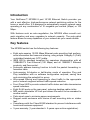
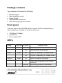
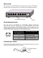
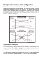
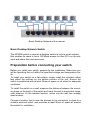
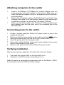
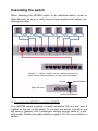
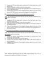
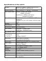
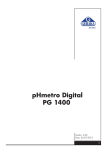
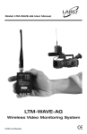
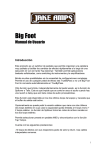
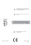
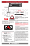
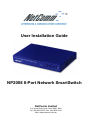
User Installation Guide
NP2008 8-Port Network SmartSwitch
NetComm Limited
2~6 Orion Road, Lane Cove, NSW, 2066
Tel: (02) 9424-2070, Fax: (02) 9424-2010
Web: www.netcomm.com.au
Table of Contents
Table of contents
Page 2
Introduction
Page 3
Key features
Page 3
Package contents
Page 4
Front panel
Page 4
LED’s
Page 4
Rear panel
Page 5
RJ-45 Network ports
Page 5
Twisted pair cables
Page 5
Straight and crossover cable configuration
Page 6
Application examples
Page 6
Preparation before connecting your switch
Page 7
Attaching computers to the switch
Page 8
Connecting power to the switch
Page 8
Verifying installation
Page 8
Cascading the switch
Page 9
Specifications of the switch
Page 11
C-Tick Mark declaration and conformance
Page 12
Warning
Page 12
Statement of conditions
Page 12
Trademarks
Page 12
Further information and technical support
Page 12
Introduction
Your NetComm™ NP2008 8 port 10/100 Ethernet Switch provides you
with a cost effective, high-performance network switching solution for the
home or small office. It is designed to automatically support network users
operating at any combination of 10 megabits per second (Mbps) or 100
Mbps.
With features such as auto-negotiation, the NP2008 offers smooth network migration and easy upgrades to network capacity. The auto-uplink
feature allows for easy expansion of your network as your needs dictate.
Key features
The NP2008 switch has the following key features:
• Eight auto-sensing 10/100 Mbps Ethernet ports providing high performance information and resource sharing, using simple Category 5 (Cat5)
unshielded twisted pair (UTP) cable.
• IEEE 802.3x standard compliant for seamless interoperation with all
100BASE-TX Fast Ethernet (100 Mbps) and all 10BASE-T Ethernet
products, and flow control.
• Automatic address learning function to build the packet forwarding information table.
• Auto-sensing full-duplex or half-duplex mode of operation Plug and
Play installation with no software configuration required, saving time
and minimizing the potential for errors.
• Wire-speed filtering and forwarding to direct traffic to the appropriate
port or network segment without traffic speed reduction.
• Front Panel LED’s provide network traffic status and data transmission
speed indicators.
• Eight RJ-45 ports on the rear panel, reducing desktop cable clutter
• MDI switch selectable UP-Link port allows the switch to be cascaded to
another switch.
• Palm sized case to minimize space requirements.
• Rugged metal enclosure with choice of wall mounting slots or rubber
feet.
• Compliance with the Class B EMI standard to prevent interference with
home and business equipment.
• 3-year warranty (1-year standard + 2-years upon online registration).
Package contents
Your package will contain the following:
•
•
•
•
•
NP2008 switch
User installation guide
Power Supply
Self adhesive rubber feet
Wall mounting plugs and screws
Front panel
The front panel of the NP2008 switch contains LED’s corresponding to
each network port located on the back of the hub:
• 100 Mbps (10 Mbps).
• Link/activity.
• Plus a power LED.
LED’s
LABEL
Pwr (Power)
100M
Link/Act
COLOUR
STATUS
Green
On
Power is connected to the device.
Off
Power has been disconnected.
On
The port is operating in 100Mbps mode.
Off
The port is operating in 10Mbps mode.
Off
There is no network connection.
On
The port has established a valid network
connection.
Green
Green
Blinking
DESCRIPTION
Data is being received or transmitted .
Rear panel
The rear panel of the NP2008 switch has eight auto-sensing 10/100 Mbps
Ethernet ports and a power jack for connection of the supplied plug-pack.
8 x RJ45 10/100 Ports
Power
RJ-45 Network ports
All of the ports on the NP2008 are 10/100 Mbps capable auto-sensing
Ethernet ports. Each port supports only unshielded twisted pair (UTP) cable
using an 8-pin RJ-45 plug. The NP2008 provides an UP-Link feature for cascading multiple switches. Port 8 can been configured as a normal switch port
or as an UP-Link port utilising the UP-Link selection switch .
RJ-45 Connector
Pin Assignment
1
2
3
6
4,5,7,8
Normal Assignment
Input Receive Data +
Input Receive Data Output Transmit Data +
Output Transmit Data Not used
Twisted pair cables
These following diagrams illustrate the use of straight-through and crossover
twisted pair cables along with the connector.
RJ-45 plug attached
to cable
Pin 8
Straight and crossover cable configuration
For two devices to communicate, the transmitter of each device must be connected to the receiver of the other device. The crossover function is usually
implemented internally as part of the circuitry in the device. Most ports on
switches and repeaters have media-dependent interfaces with crossover
ports. These ports are referred to as MDI-X or normal ports. Computer and
workstation adapter cards are usually media-dependent interface ports referred to as MDI or uplink ports.
Application examples
The NP2008 switch is designed to provide full flexibility in configuring your network connections. The switch can be used as a standalone device or it can be
used up linked to other 10Mbps, 100Mbps hubs, switches or other interconnection devices such as internet gateways and routers.
The configuration example over illustrates the NP2008 in a basic network environment connected to several Desktop PC’s sharing files and peripherals.
Basic Desktop Network with no server.
Basic Desktop Network Switch
The NP2008 switch is used as a desktop switch to build a small network
that enables its users to have 100 Mbps access to other PC’s on the network and share files and resources.
Preparation before connecting your switch
Before you install your switch, prepare for the installation. Make sure you
will be operating the unit within the specified voltage and temperature limits.
To install your switch on a flat surface, simply install the included rubber
feet within the outlines on the bottom surface of the unit. Ensure the
switch is positioned with at least 50mm of space on all sides for adequate
ventilation.
To install the switch on a wall, measure the distance between the mounting holes on the back of the switch and mark the wall to match that measured distance. At the marked location, screw into the wall two suitably
sized screws.
Choose a location that is near the devices to be connected, is close to a
suitable electrical outlet, and provides at least 50mm of space all around
the switch for ventilation.
Attaching computers to the switch
1.
2.
3.
Install a 10/100Mbps (10/100Base-TX) network adapter card into
every computer you want to attach to the network. Make sure you
install the Network adaptor drivers in accordance with the manufacturers directions.
Prepare the twisted-pair cables with RJ-45 plugs on each end. Use
Category 5/5e cable for all connections. Make sure the cable length
is less than or equal to no more than 100 meters (328 feet).
Attach one end of the cable to the RJ-45 port of the computer’s network adapter card and the other end to any available port of the
NP2008 switch.
Connecting power to the switch
1.
2.
3.
4.
5.
Locate a suitably switched 240volt AC power outlet to plug in the
supplied power pack.
Make sure that the power switch on the outlet is switched OFF before
inserting the power pack into the 240volt AC power outlet.
Insert the power pack into the power outlet.
Connect the cable attached to the power pack adapter to the power
inlet on the rear panel of the switch.
Switch on the power switch on the 240volt AC power outlet.
Verifying installation
When power has been applied to the switch the switch will display:
1.
2.
The green Pwr (power) LED on the front panel is on.
The green Link LED on each connected port is on.
When the switch is connected and operating, refer to the table in “LED’s”
for information about the LED’s and their activity.
Verifying Installation
Cascading the switch
When attaching the NP2008 switch to an additional switch, router or
other devices, be sure to verify the port type implemented before connecting any cable.
“Normal” or “Uplink” modes can be selected through the
uplink selector switch located on the right side of the switch.
Normal
Uplink Enabled
Right side view
Uplink Select Switch
A) Connecting the NP2008 to another NP2008:
Your NP2008 switch supports a switch selectable UP-Link port, port 8
located on the rear of the switch. To connect one switch to another you
will need a Category 5/5e Twisted-pair straight through cable of a suitable length. Please see cable details on page 5 & 6 for more details on
cables.
1.
2.
3.
4.
Locate the UP-Link slide switch located on the right hand side of the
switch case.
Slide the selection switch to the UP-Link position.
Connect one end of a straight through cable to the number 8 port on
the first NP2008 switch.
Connect the other end of the straight through cable to any port of the
second NP2008 switch, see previous diagram for more details.
B) Connecting One NP2008 to another Manufacturers switch:
Note: The following instructions assume that the NetComm NP2008 is the
first switch in the chain.
1.
2.
3.
4.
Locate the UP-Link slide switch located on the right hand side of the
NP2008 switch case.
Slide the selection switch to the UP-Link position.
Connect one end of a straight through cable to the number 8 port on
the NP2008 switch.
Connect the other end of the straight through cable to any port of the
second switch. Refer to any details provided by the manufacturer of
the second switch.
C) Connecting One NP2008 to another Manufacturers switch:
Note: The following instructions assume that the NetComm NP2008 is the
secondary switch in the chain.
1.
2.
3.
4.
Follow the switch manufacturers instructions for setting your first
switch into UP-Link mode.
Locate the UP-Link port on your first switch.
Connect one end of a straight through cable to the UP-Link port on
your first switch.
Connect the other end of the straight through cable to any port of the
NP2008 switch.
Note: Ethernet specifications limit the cable length between your PC or
server and the switch to 328 feet (100 meters).
Specifications of the switch
Standard
IEEE802.3 10Base-T Ethernet IEEE 802.3u &
802.3x 100 Base-TX Fast Ethernet
Network Interface
Eight 100BASE-TX / 10BASE-T N-Way ports
Data Transfer Rate
Ethernet: 10Mbps (half duplex)
20Mbps (full duplex)
Fast Ethernet: 100Mbps (half duplex)
200Mbps (full duplex)
Network Cable
10 BASE-T: Cat.3, 4 or 5 UTP Cables (100-ohm
impedance)
100BASE-TX: Cat. 5 UTP Cables (100-ohm impedance)
Topology
Star
Buffer Memory
2M Bits
Transmission Method Store and forward
Filter/Forward
14880 pps / 10 BASE-T port
148800 pps / 100 BASE-TX port
MAC Address Table
Up to 8K
LED Indicators
Per Device
Power
Per Port
100Mbps, LINK/ACT
Flow control
Pause frame (Full-duplex)
Back-pressure (Half-duplex)
Duplex mode
Supports both half-duplex and full-duplex mode
Power Supply
External Power Pack
9volts DC, 1000ma
EMI
FCC Class A / CE Mark / C-Tick
Temperature
0 ~ 40 Degree Celcius
Humidity
5% ~ 90%
Dimensions
147mm x 92mm x 22mm (L x W x H)
Housing
Metal
Safety
TUV, CUL
Warranty
3 Years - 1 year Standard + 2 additional with OnLine registration
C-Tick Mark declaration of conformance
This is to certify that this product complies with the Australian C-Tick
standard where applicable.
Warning
Do not plug a phone jack connector into any of the RJ-45 port. This
may damage the switch.
Statement of conditions
In the interest of improving internal design, operational function, and/or
reliability, NetComm reserves the right to make changes to the product
described in this document without notice. NetComm does not assume
any liability that may occur due to the use or application of the product(s)
or circuit layout(s) described herein.
Trademarks
NetComm™ is a trademark of NetComm Limited. Windows® is a registered trademark of Microsoft Corporation. Other brand and product
names are trademarks or registered trademarks of their respective holders. Information is subject to change without notice. All rights reserved.
Further information and technical support
For further information or technical support please review NetComm’s
extensive Web knowledge base at www.netcomm.com.au or contact our
customer response centre on telephone Sydney (02) 9424-2070.
NetComm Limited.
2~6 Orion Road
LANE COVE NSW 2066
Sydney Australia.
© 2001 by NetComm Limited. All rights reserved.