1
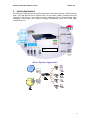
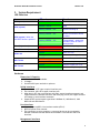
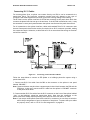
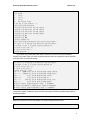
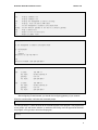
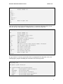
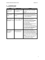
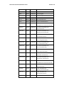
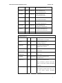
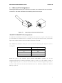
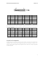
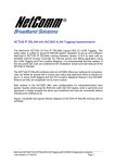
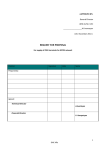
Installation Guide NCT240 IP DSLAM NetComm NCT240 Installation Guide Release 1.0 Table of Content 1. INTRODUCTION ................................................................................................................................ 3 FEATURES .................................................................................................................................................... 4 2. SYSTEM APPLICATION (UPDATE PICTURE!!!)......................................................................... 5 3. SYSTEM REQUIREMENT ................................................................................................................ 6 LED DEFINITION ......................................................................................................................................... 6 HARDWARE ................................................................................................................................................. 6 SOFTWARE FEATURE ................................................................................................................................... 7 4. INSTALLATION PROCEDURE........................................................................................................ 9 EQUIPMENT CHECKLIST .............................................................................................................................. 9 MOUNTING ................................................................................................................................................ 10 INSTALLING OPTIONAL MODULES ..............................................................................................................11 DESKTOP OR SHELF MOUNTING ................................................................................................................ 13 WALL MOUNT MOUNTING ......................................................................................................................... 14 PROPER GROUNDING (EARTH).................................................................................................................... 15 INSTALLING AN SFP TRANSCEIVER ........................................................................................................... 16 CONNECTING TO THE 1000BASE-T AND 10/100BASE-TX INTERFACE .................................................... 16 CONNECTING RJ-21 CABLES ..................................................................................................................... 17 CONSOLE MANAGEMENT ........................................................................................................................... 18 5. TROUBLESHOOTING..................................................................................................................... 23 TROUBLESHOOTING GUIDE ........................................................................................................................ 23 ALARM DEFINITION ................................................................................................................................... 24 6. CABLE AND PIN ASSIGNMENT.................................................................................................... 28 10BASE-T/100BASE-TX PIN ASSIGNMENTS .......................................................................................... 28 1000BASE-T PIN ASSIGNMENTS .............................................................................................................. 29 RJ-21 PORT PIN ASSIGNMENTS ................................................................................................................. 29 CONSOLE PORT PIN ASSIGNMENTS ............................................................................................................ 30 7. OBTAINING TECHNICAL ASSISTANCE ..................................................................................... 32 ACCESSORIES FOR NETCOMM NCT240 .................................................................................................... 32 8. SPECIFICATION............................................................................................................................... 33 HARDWARE ............................................................................................................................................... 33 SOFTWARE FEATURE ................................................................................................................................. 34 9. GLOSSARY ........................................................................................................................................ 35 2 NetComm NCT240 Installation Guide Release 1.0 1. Introduction This document is intended for First Office Acceptance test plan for NetComm’s ADSL2+ Broadband Access Switch solution (BAS). The Netcomm NCT240 Broadband Access Switch contains 24 ADSL2/2+ circuits to deliver high-speed data, video and voice service over traditional twisted copper pairs by using DSL technology. To meet the increasing demand for high-speed internet access and triple play application services. The next generation network offers a feasible functionality of integrated services with the most cost effective architecture. Next generation broadband access networks are designed to provide rich video contents, DSL, POTS and VoIP services over traditional copper wire infrastructure. These types of services will be supported on NGN architecture simultaneously. DSL is used as the data service platform for traditional POTS technology which is used for voice services. The multimedia and local content-rich applications can also be easily implemented on this NGN architecture. xDSL (Digital Subscriber Line) is a technology for delivering high-bandwidth information over copper telephone lines. xDSL service can deliver POTS and high date rate services simultaneously over a single twisted-wire pair. The POTS and data service are simultaneous and independent; the xDSL data service does not affect the POTS service. xDSL uses the bandwidth above the 4-kHz POTS frequency to transmit duplex data using digital modulation techniques from the C.O side to the Customer Premises Equipment (CPE). ADSL is a form of xDSL service that delivers an asymmetric data rate over a twisted copper pair. ADSL delivers a higher rate downstream, towards the customer premises and lower rate upstream, from the customer premises. ITU standard compliant Full-Rate ADSL2+ can deliver data rates up to 25 Mbps downstream and 1 Mbps upstream; Full-Rate ADSL can deliver data rates up to 8 Mbps downstream and 800 kbps upstream; G.Lite ADSL can deliver up to 1.5 Mbps downstream and 512 kbps upstream. The actual data rate depends on the length, gauge, and condition of the twisted-wire pair, the bandwidth of the uplink depends on the data network, and the capacity of the network service provider. Digital Subscriber Line (DSL) dominates broadband market. The position of national telecom operators in most countries has given the advantage in reaching out to customers with broadband services over DSL. The NCT240 Access system contains 24 ADSL2/2+ circuits to deliver high-speed data service over twisted copper pairs using industry standard Discrete Multi-Tone (DMT) line coding technology. The NCT240 complies with full-rate ADSL in accordance with ANSI T1.413 Issue 2, ITU-T G.992.1 (G.dmt), ITU-T G.992.2 (G.lite)ITU-T G.992.3 (ADSL2) and ITU G.992.5 (G.ADSL2+) protocols. The NCT240 greatly expand broadband capabilities in the access network, enhancing the infrastructure for emerging services. With simple in-service upgrades, service providers obtain the capacity and Quality of Service (QoS) to support larger populations of narrowband and broadband users. For management, NCT240 can be easily configured by SNMP, Telnet, SSH, HTTP, HTTPS and RS-232 console. 3 NetComm NCT240 Installation Guide Release 1.0 Features Complete Intelligent L2 switch feature Intelligent DSL interworking feature RFC2684 MpoA VPN pass-through RFC2516 PPPoE packet forwarding. Advanced L2+/higher layer protocol & policy control GVRP (IEEE 802.1q) STP/RSTP (IEEE 802.1d/w) IGMP Snooping DHCP relay and relay agent option 82 Packet inspection and do policy control (filtering, forwarding..) Security of authentication mechanism and encryption SSH/SSL Rich user interface for management including security CLI/Telnet/SSH/SNMP/HTTP/S-HTTP Variety of uplink interface SFP for 1000 Base-SX, LX, LHX and ZX. RJ45 for 1000 Base-TX. Remote software upgrade 4 NetComm NCT240 Installation Guide Release 1.0 2. System Application The following figures present the system application in the access network. NCT240 provides video, voice and data service for different users, such as Hotels, SOHOs, residential users and enterprises. The end user can use DSL for Various applications such as Telecommuting, Video streaming, On-line game, IPTV, Distance learning, Telemedicine, Voice over IP and Video conferencing...etc. EMS: Element Management Switch Basic System Application ADSL2+ Modem PSTN PBX or DLC ADSL2+ (1) PC BAS-8124 ADSL2+ (2) ADSL (3) .. PC CIT Internet PC BRAS Aggregator Switch ADSL2 (24) .. PC EMS 5 NetComm NCT240 Installation Guide Release 1.0 3. System Requirement LED Definition Items LED color Function PWR (power) GREEN – SOLID Power on GREEN – SOLID System finished initializing stage Flashing GREEN – 2Hz System is booting up SYS (system) MAJ (Major alarm ) RED System is ready to restart – release the ACO/RST button to restart System is ready to reset to Factory default – release the ACO/RST button to reset to factory default Major alarm reporting MIN ( Minor alarm ) AMBER Minor alarm reporting GREEN ADSL link is UP Flashing GREEN DSL line is training (to linkup) AMBER Ethernet Fiber port is UP Flashing AMBER Dataflow activity in the port GREEN Ethernet Copper port is UP Flashing GREEN Dataflow activity in the port Flashing GREEN – 4Hz SYS (system) - When the ACO/RST button is pressed Flashing GREEN – 1Hz ADSL link GE-FX Link GE-TX Link Hardware Dimensions & Capacity 1. 19” wide rack mount available. 2. 1U height 3. Provide 24 DSL ports and built-in splitters. Uplink Interfaces 1. The connector is SFP type at optical interface port. 2. The connector is RJ-45 at copper interface port. 3. When plug in SFP, the work interface will select optical interface automatic and copper interface is assistant interface. And when plug out SFP, the copper interface will change to work interface automatic. 4. Supported SFP optical module types have 1000 Base-SX, 1000 Base-LX, 1000 Base-LHX and 1000 Base-ZX. Line Interfaces 1. Support 24 ports ADSL2+ line interface module (ATU-C). 2. Build in Splitter/Filter internal. 3. The connectors are wire-wrapping; a converter device can be connected in between interfaces and user device at both ADSL2+ line interface and PSTN interface. Management Interfaces 6 NetComm NCT240 Installation Guide Release 1.0 1. One Ethernet interface (RJ45) support Full Duplex and Half Duplex transceiver function, conforms to IEEE 802.3 Auto-Negotiation standard and comply with IEEE802.3 Ethernet, IEEE802.3u Fast Ethernet. 2. One RS232 console interface (DB9) support Full Duplex, 1、2 stop bits and odd、 even、none parity check. The baud rate range:1200 baud rate ~ 921000 baud rate. Power Supply 1. 60Wt. (input 90~260 VAC(10%), 50~60Hz) 2. 60Wt. (input –36~-72 VDC) Operating Requirement 1. 2. 3. 4. Temperature: -10ºC ~ 60ºC. Humidity: 10~90% (non-condensing). EMC/ESD Certification: FCC Part15 Class A. Safety Certification : UL60950 ADSL/ADSL2+ Interface 1. 2. 3. 4. 5. ITU-T G.992.1 (G.dmt) [Annex A], ITU-T G.992.2 (G.lite) [Annex A] ITU-T G.992.3 (ADSL2) [A,L], ITU-T G.992.5 (ADSL2+) [A,L] OAM functionality according to ITU-T G.997.1 (G.ploam) ANSI T1.413 Issue 2 Line loop back and diagnostic Software Feature L2/L3 Functionality 1. 2. 3. 4. 5. 6. 7. Switch capability: IEEE802.3x flow control, IEEE802.1d bridging. VLAN: IEEE802.1p/q VLAN (4094), stacked VLAN, Port-based and Tag-based. Multicasting: IGMP snooping, 250 groups, Dynamic & Static Configuration. QoS: IEEE802.1p based COS, 4 priority output queue per port, RFC 2475 DiffServ/TOS. DHCP: DHCP relay and relay agent option 82. Rate Limitation: from 64K to Maximum rate, the step is 64K. Security: Packet policy control (filtering/forwarding) and ACL function. Interworking 1. 2. 3. RFC2684 MPoA LLC/VCMUX. VPN pass-through RFC2516 PPPoE packet forwarding. Trouble Shooting 1. 2. 3. LED indicator for power, varied interfaces and system alarms. Cable labeling Local and remote management by using serial and uplink interface ¾ On-line show link status, quality and traffic counters ¾ Loop back test ¾ Log event/alarm of system level ¾ Log event/alarm of GE and ADSL2+ interfaces Management 1. 2. 3. CLI support for local management SNMP V1/V2c Telnet/SSH 7 NetComm NCT240 Installation Guide Release 1.0 4. Web-based 5. 6. 7. 8. 9. Support FCAPS management for EMS Syslog SNTP Remote software upgrade Remote file backup and restore 8 NetComm NCT240 Installation Guide Release 1.0 4. Installation Procedure Equipment Checklist Before installing the access switch please verify that you have received all the items listed under “Package Contents.” If any of the items are missing or damaged, contact your local distributor. Also, be sure you have all the necessary tools and cabling before installing the switch and splitter. Note that these devices can be installed on any suitably large flat surface or in a standard EIA 19-inch rack. Package Contents 1. 2. 3. 4. 5. 6. 7. A NCT240 ADSL2+ IP DSLAM A Bracket Mounting Kit containing two brackets and four screws for attaching the brackets to the DSLAM One Power Cord Four adhesive foot pads One CD containing installation Guide and Management Guide One RS-232 console cable (Optional) Two RJ-21 cables (Optional) 9 NetComm NCT240 Installation Guide Release 1.0 Mounting The NCT240 may be mounted on any flat surface, such as a shelf, or in a rack. Before you start installing the access switch, make sure you can provide the right operating environment, including power requirements, sufficient physical space, and proximity to other network devices that are to be connected. Verify the following installation requirements: • Power requirements: 100 to 240 VAC (± 10%) at 50 to 60 Hz (± 3 Hz). The access switch power supplies automatically adjust to the input voltage level. Make sure that a properly grounded power outlet is within 2.5 m (8 ft) of the access switch. • The access switch should be located in a cool dry place, with at least 10 cm (4 in.)of space on the sides for ventilation. • Place the access switch out of direct sunlight, and away from heat sources or areas with a high amount of electromagnetic interference. The temperature and humidity should be within the ranges listed in the specifications. • If you intend to mount the access switch in a rack, make sure you have all the necessary mounting screws, brackets, bolts and nuts, and the right tools. • Check if network cables and connectors needed for installation are available. • Be sure the access switch is within reach of the punch-down blocks for rear panel connections that include DSL and splitter interface. 10 NetComm NCT240 Installation Guide Release 1.0 Installing Optional Modules Before mounting the switch, be sure you install any optional modules. If you have purchased an optional slide-in 1000BASE-T, SFP 1000BASE-X, install it now, and following the instructions below. To rack-mount devices: 1. Attach the brackets to the device using the screws provided in the Bracket Mounting Kit. Figure 4-1. Attaching the Brackets 2. Mount the device in the rack, using four rack-mounting screws. 11 NetComm NCT240 Installation Guide Release 1.0 Figure 4-2. Installing the Switch in a Rack 3. If installing a single switch only, turn to “Powering On the Switch” at the end of this chapter. 4. If installing several devices, we recommend using one stack for the switch, and another for the others. This will keep the cabling straight and easy to maintain. 12 NetComm NCT240 Installation Guide Release 1.0 Desktop or Shelf Mounting 1. Attach the four adhesive feet to the bottom of the first switch. Figure 4-3. Attaching the Adhesive Feet 2. Set the device on a flat surface near an AC power source, making sure there are at least two inches of space on all sides for proper air flow. 3. If installing a single switch only, go to “Powering On the Switch” at the end of this chapter. 4. If installing multiple switches, attach four adhesive feet to each one. Place each device squarely on top of the one below, in any order. 13 NetComm NCT240 Installation Guide Release 1.0 Wall mount Mounting 1. Attach the four adhesive feet to the bottom of the first switch. Figure 4-4. Installing the Switch on a Wall 2. Set the device on a flat surface near an AC power source, making sure there are at least two inches of space on all sides for proper air flow. 3. If installing a single switch only, go to “Powering On the Switch” at the end of this chapter. 4. If installing multiple switches, attach four adhesive feet to each one. Place each device squarely on top of the one below, in any order. 14 NetComm NCT240 Installation Guide Release 1.0 Proper grounding (earth) Proper Grounding is a very important part of the electrical installation for NCT240, if noise is present in the Electrical ground this noise can leak to the ADSL circuit through the Surge protectors and interfere with the proper operation of ADSL links. *** both AC/DC power supplies are isolated from the NCT240 ground therefore the Grounding procedure is the same regardless of what the power supply is . NCT240 Ground: Grounding procedure: (FIX Picture) NCT240 NCT240 15 NetComm NCT240 Installation Guide Release 1.0 Installing an SFP Transceiver NCT240 Figure 4-5. Inserting an SFP Transceiver into the Slot To install an SFP transceiver, do the following: 1. Use your cabling requirements to select an appropriate SFP transceiver type. 2. Insert the transceiver with the LC connector facing outward and the slot connector facing down. Note: SFP transceivers are keyed so they can only be installed in one orientation. 3. Slide the SFP transceiver into the slot until it clicks into place. Notes: 1. If the stacking ports are connected, the SFP port will be disabled. 2. SFP transceivers are hot-swappable. You do not need to power off the switch before installing or removing a transceiver. However, you should always first disconnect the network cable before removing a transceiver. Connecting to the 1000BASE-T and 10/100BASE-TX Interface Each device requires an unshielded twisted-pair (UTP) cable with RJ-45 connectors at both ends. For 1000BASE-T connections, Category 5, 5e or better cable is required; for 100BASE-TX connections, Category 5 cable is required; for 10BASE-TX, Category 3,4, or 5 cable can be used. The RJ-45 ports on the NCT240 modules support automatic MDI/MDI-X operation, so you can use standard straight-through twisted-pair cables to connect to any other network device (PCs, servers, switches, routers, or hubs). Note: Auto-negotiation must be enabled for automatic MDI/MDI-X pin out configuration. See Appendix B for further information on cabling. 16 NetComm NCT240 Installation Guide Release 1.0 Connecting RJ-21 Cables For incoming phone lines, a splitter can connect directly to a PBX or can be connected via a punch-down block. The particular connection method used will depend on the type of connectors and cables supported on the PBX, and on the existing cabling in the building. The EE lines from the splitter interface of NCT240 are connected to the punch-down block that connects the phone lines that run up to the end users. If the NCT240 is installed in a rack, it may be convenient to use a patch panel between the splitter interface and the punch-down block. For all connections to the splitter interface, cables with standard Telco RJ-21 connectors must be used. Some punch-down blocks can be pre-wired with an RJ-21 connector provided, making the connection simple. Otherwise, a cable with an RJ-21 on one end and free wiring on the other end will be required. Figure 4-6. Connecting to the Punch-down Blocks Follow the steps below to connect an EE Splitter to a building’s phone-line system using a punch-down block: 1. Connect one RJ-21 flat cable from the PBX to the connector on the splitter’s rear panel labeled “PBX/MDF.” Note: Some installations may also have a separate punch-down block between the PBX and the EE Splitter. In this case, connect an RJ-21 cable from the splitter’s “PBX/MDF” connector to the punch-down block. 2. Connect another RJ-21 flat cable from the RJ-21 connector on the front of the splitter labeled “Line” to the building’s phone-line punch-down block. Note that the connection to the punch-down block usually requires punching down the free wires from the RJ-21 cable. Note: If you use pre-wired punch-down blocks with RJ-21 connectors, be sure they are wired to match the pin assignments of ports on the back of the splitter. To ensure that your cables are properly wired, refer to “RJ-21 Port Pin Assignments” on page B-6. 17 NetComm NCT240 Installation Guide Release 1.0 Console management 1. HyperTerminal setting 2. Bootloader startup If you not press any key in the below state, system will load the default startup sequence to do boot our system. U-Boot 1.1.3 (Jun 29 2006 - 16:38:55) BAS ver:1.00.07 U-Boot code: 00200000 -> 0021CBCC BSS: -> 0022120C RAM Configuration: Bank #0: 00000000 128 MB Flash: 32 MB In: serial Out: serial Err: serial Net: No ethernet found. Hit any key to stop autoboot: 3 RTC clock initial start !!! RTC clock initial end !!! Scanning JFFS2 FS: U-Boot 1.1.3 (Jun 29 2006 - 16:38:55) BAS ver:1.00.07 U-Boot code: 00200000 -> 0021CBCC BSS: -> 0022120C RAM Configuration: 18 NetComm NCT240 Installation Guide Release 1.0 Bank #0: 00000000 128 MB Flash: 32 MB In: serial Out: serial Err: serial Net: No ethernet found. Hit any key to stop autoboot: 3 Please choose booting method: 1--Startup from old kernel and old ramdisk 2--Startup from new kernel and old ramdisk 3--Startup from old kernel and new ramdisk 4--Startup from new kernel and new ramdisk 5--Startup from NFS 6--Startup from RAM 7--U-boot command line Please choose booting method by pressing the option number: Your choice is: 4--Startup from new kernel and new ramdisk Do you want to save it as default booting method? y/n RTC clock initial start !!! RTC clock initial end !!! Scanning JFFS2 FS: | If you press a key during this state, there is a menu for you to do a choice the startup sequence you prefer. After you choice a startup sequence this time, system will ask you whether save this choice for next time startup. Your choice is: 4--Startup from new kernel and new ramdisk Do you want to save it as default booting method? y/n RTC clock initial start !!! RTC clock initial end !!! Scanning JFFS2 FS: done. -rw------- 8068015 Thu Jan 05 12:03:55 2006 uImage.ramdisk -rw------- 1081250 Thu Jan 05 12:03:48 2006 uimage.kernel drwx-----0 Thu Jun 08 03:08:47 2006 config drwxr-xr-x 0 Thu Jan 05 12:26:25 2006 aa -rw------1187 Thu Jan 05 19:28:29 2006 telnet_info1 drwx-----0 Thu Jan 05 12:01:20 2006 update ### JFFS2 loading 'update/newkernel.image' to 0x3000000 ### JFFS2 load complete: 1081262 bytes loaded to 0x3000000 ### JFFS2 loading 'update/newramdisk.image' to 0x5000000 In this state, system will take two~three minutes to do system initialize, so please have patience with this procedure. BAS> Before you connect PC to NCT240 system, you should configure Ethernet first. BAS>ip 19 NetComm NCT240 Installation Guide Release 1.0 BAS/ip>? help ? show arp set gateway ping root exit Display command list Display command list Display the management ip adress settings Display, flush the device ARP table Set the management ip address and subnet mask Set the default gateway of the device's default gateway Ping a remote host Return to the root directory. Return to upper level BAS/ip>set Set the management ip address and subnet mask set <ip|netmask> ip . netmask . BAS/ip>set ip ixp0 192.168.1.1 Done BAS/ip>set netmask ixp0 255.255.255.0 BAS/ip>show ixp0 ip addr: mac addr: gateway: net mask: 192.168.1.1 00:05:ca:00:42:11 0.0.0.0 255.255.255.0 eth0 ip addr: mac addr: gateway: net mask: 192.168.0.1 00:05:ca:00:42:15 0.0.0.0 255.255.255.0 After configuring IP and Netmask, you should also configuring gateway of your network. When the console starts, it will show the command prompt. BAS> You can type help or ?, and it will show all the command groups in this program. This program has seven groups: sys, adsl, switch, isolation, ip, staticstics, and config. User can type end to terminate this program, or to type test to enter the test program. BAS>help 20 NetComm NCT240 Installation Guide Release 1.0 help Display command list ? Display command list < sys > < adsl > < status > < switch > < ip > < statistics > < config > exit Return to upper level BAS0> Type sys to enter the sys group, and then type help or ? to show the information about the sys. User can also type “help argument” to display that how to execute this argument. BAS/sys>help help ? daisycontrol update info user reboot snmp server syslog time date timeserver alarm exit BAS0/sys> Display command list Display command list The management of daisy chain Update system version Show general system information Setup user information Reboot the system SNMP information The device's service status and port numbers information Log the system status and exception The system's current time The system's current date The system's time server The recorded system alarm Return to upper level Ex. type “help info” command, system will show the message about this argument of info. Like following figure, program will display the command of info and its arguments. BAS/sys>help info Show general system information. info <show|switchname|location|contact|phone> show Display general system information. switchname Set the switch name. location Set the location information. contact Set the contact person information. phone Set the contact phone number. 21 NetComm NCT240 Installation Guide Release 1.0 And we can type the command of exit to leave the group sys, and this program will show following figure BAS> If our location is in top of the level, and we want to terminate this program. We can type end to terminate the program, like following figure. BAS>end BAS comand line program ended ! Above description, we only tell user the method about group sys, and the methods of other groups like the same way. And we can type help to show the purpose of each group and its command. 22 NetComm NCT240 Installation Guide Release 1.0 5. Troubleshooting Troubleshooting guide Trouble PWR indicator does not light up after Turning on the power. Possible cause Solution Power outlet, power cord, • Check the power outlet by plugging in or internal power supply another device that is functioning may be defective. properly. • Check the power cord with another device. SYS indicator does Microprocessor, SDRAM, • Verify that the switch are powered on. not light up after Flash or Software may be • Check the boot-up statement from console. The boot up procedure is Boot startup. defective. -> kernel->application • ADSL2+ LINK NCT240 Switch, cabling, • Verify that the Access Switch and indicator does not ADSL Line, or ADSL Switch attached CPE are powered on. • Be sure the RJ-21 cables are plugged light up after making Ports may be defective. into the Access Switch from ADSL2+ a connection. modem through the Phone-line punch-down block. • Verify that the cable length does not exceed specified limits. • Check the cable connections on the access Switch, punch-down block/patch panel, and the Extended Ethernet CPE for possible defects. Replace the defective cable if necessary. UP LINK indicator Network cable or Ethernet • Verify that the access switch and does not light up device attached to this attached device are powered on. • Be sure an Ethernet cable is plugged into after making a port may be defective. both the switch and attached device. connection. • Verify that the proper cable type is used and its length does not exceed specified limits. • Check the network cable connections for possible defects. Replace the defective cable if necessary. 23 NetComm NCT240 Installation Guide Release 1.0 Alarm definition 1. Information about this Alarm Definition. The NCT240 alarm system have two ways that to make a sound by external alarm out or LED signal on faceplate to indicate an error condition. In this document, we declare the alarm as follow format: Alarm Type Alarm Level Alarm Group Alarm Description Alarm Level: Major/Minor Alarm Group: System/CGC group/GEMINAX Group 2. System alarm The system alarms are triggered by ALARM OUT or kernel oops. Alarm Type Alarm Level Alarm Group Alarm Description DoorOpen PowerFail TemDetect Major Major Major sys Sys Sys Device has been opend Power failure Fire/ High temperature Table 1 System Alarm 3. CGC alarm The CGC alarms are including the GE ports errors. Alarm Type GE port0 down GE port1 down Alarm Level Alarm Group Alarm Description link Major CGC GE port0 link down link Major CGC GE port1 link down Table 2 CGC Alarm 4. GEMINAX alarm The GEMINAX alarm includes the alarms on the ports. Alarm Type Alarm Level Alarm Group Alarm Description 24 NetComm NCT240 Installation Guide Release 1.0 LPR Major GEMINAX Loss-of-power LOF Major GEMINAX Loss-of-frame LOS Major GEMINAX Loss-of-signal LOM Major GEMINAX loss-of-margin LOL Major GEMINAX Loss of Link NCD Major GEMINAX No Cell Delineation LCD Major GEMINAX Loss of Cell Delineation 15M FECS Major GEMINAX 15 minutes threshold error Forward Error Correction Seconds 15M ES Major GEMINAX 15 minutes threshold error Errored Seconds 15M SES Major GEMINAX 15 minutes threshold error Severely Errored Seconds. 15M UAS Major GEMINAX 15 minutes threshold error Unavailable Seconds. 15M LOSS Major GEMINAX 15 minutes threshold error Loss of Signal Seconds. 15M LOFS Major GEMINAX 15 minutes threshold error Loss of Frame Seconds. 15M LOLS Major GEMINAX 15 minutes threshold error Loss of Link Seconds. 15M LPRS Major GEMINAX 15 minutes threshold error Loss of Power Seconds. 15M FIFAIL Major GEMINAX 15 minutes threshold error Failed full initializations 15M SIFAIL Major GEMINAX 15 minutes threshold error Failed short initializations 1D FECS Major GEMINAX 1 Day threshold error Forward Error Correction Seconds 1D ES Major GEMINAX 1 Day threshold error Errored Seconds 1D SES Major GEMINAX 1 Day threshold error Severely Errored Seconds 1D UAS Major GEMINAX 1 Day threshold error Unavailable Seconds. 1D LOSS Major GEMINAX 1 Day threshold error 25 NetComm NCT240 Installation Guide Release 1.0 Loss of Signal Seconds 1D LOFS Major GEMINAX 1 Day threshold error Loss of Frame Seconds 1D LOLS Major GEMINAX 1 Day threshold error Loss of Link Seconds. 1D LPRS Major GEMINAX 1 Day threshold error Loss of Power Seconds. 1D FIFAIL Major GEMINAX 1 Day threshold error Failed full initializations 1D SIFAIL Major GEMINAX 1 Day threshold error Failed short initializations 15M FEC Major GEMINAX 15 minutes threshold error Forward Error Corrections. 15M CV Major GEMINAX 15 minutes threshold error Coding Violations 1D FEC Major GEMINAX 1 Day threshold error Forward Error Corrections. 1D CV Major GEMINAX 1 Day threshold error Coding Violations 15M HEC Major GEMINAX 15 minutes threshold error Header Error Control 15M Major GEMINAX TOTALCELL 15M Total cells Major GEMINAX USERCELL 15M IBE 15 minutes threshold error 15 minutes threshold error User cells Major GEMINAX 15 minutes threshold error Cell Bit Error 15M CRC_P Major GEMINAX 15 minutes threshold error non pre-emptive packets with CRC error in the bearer channel threshold crossing. 15M CRCP_P Major GEMINAX 15 minutes threshold error Pre-emptive packets with CRC error in the bearer channel threshold crossing. 26 NetComm NCT240 Installation Guide 15M CV_P Release 1.0 Major GEMINAX 15 minutes threshold error non pre-emptive packets with coding violation in the bearer channel threshold crossing. 15M CVP_P Major GEMINAX 15 minutes threshold error pre-emptive violation in packets the with bearer coding channel threshold crossing. 1D HEC Major GEMINAX 1 Day threshold error Header Error Control 1D Major GEMINAX TOTALCELL Total cells 1D Major GEMINAX USERCELL1D 1D IBE 1 Day threshold error 1 Day threshold error User cells Major GEMINAX 1 Day threshold error Cell Bit Error 1D CRC_P Major GEMINAX 1 Day threshold error non pre-emptive packets with CRC error in the bearer channel threshold crossing. 1D CRCP_P Major GEMINAX 1 Day threshold error Pre-emptive packets with CRC error in the bearer channel threshold crossing. 1D CV_P Major GEMINAX 1 Day threshold error non pre-emptive packets with coding violation in the bearer channel threshold crossing. 1D CVP_P Major GEMINAX 1 Day threshold error pre-emptive violation in packets the with bearer coding channel threshold crossing. Table 3 GEMINAX Alarm 27 NetComm NCT240 Installation Guide Release 1.0 6. Cable and Pin Assignment Following illustrates how the pins on the RJ-45 connector are numbered. Be sure to hold the connectors in the same orientation when attaching the wires to the pins. Figure 5-1. Connecting to the Punch-down Blocks 10BASE-T/100BASE-TX Pin Assignments For 100BASE-TX/10BASE-T connections, a twisted-pair cable must have two pairs of wires. Each wire pair is identified by two different colors. For example, one wire might be red and the other, red with white stripes. Also, an RJ-45 connector must be attached to both ends of the cable. With 100BASE-TX/10BASE-T cable, pins 1 and 2 are used for transmitting data, and pins 3 and 6 for receiving data. Pin Number Assignment 1 Tx+ 2 Tx- 3 Rx+ 6 Rx- Because the ports on the NCT240 support automatic MDI/MDI-X operation, you can use straight-through cables for all network connections to PCs or servers, or to other switches or hubs. In straight-through cable, pins 1, 2, 3, and 6, at one end of the cable, are connected straight through to pins 1, 2, 3 and 6 at the other end of the cable. The table below shows the 10BASE-T/100BASE-TX MDI and MDI-X port pin outs. 28 NetComm NCT240 Installation Guide Release 1.0 Pin MDI-X Assignment MDI Assignment 1 Input Receive Data + Output Transmit Data + 2 Input Receive Data - Output Transmit Data - 3 Output Transmit Data + Input Receive Data + 6 Output Transmit Data - Input Receive Data - Note: Auto-negotiation must be enabled for automatic MDI/MDI-X pinout configuration. 1000BASE-T Pin Assignments 1000BASE-T ports support automatic MDI/MDI-X operation, so you can use straight-through cables for all network connections to PCs or servers, or to other switches or hubs. The table below shows the 1000BASE-T MDI and MDI-X port pinouts. These ports require that all four pairs of wires be connected. Note that for 1000BASE-T operation, all four pairs of wires are used for both transmit and receive. Use 100-ohm Category 5, 5e or better unshielded twisted-pair (UTP) or shielded twisted-pair (STP) cable for 1000BASE-T connections. Also be sure that the length of any twisted-pair connection does not exceed 100 meters (328 feet). Pin MDI Signal Name MDI-X Signal Name 1 Transmit Data plus (TD1+) Transmit Data plus (TD2 +) 2 Receive Data minus (RD1-) Receive Data minus (RD2-) 3 Transmit Data plus (TD2+) Transmit Data plus (TD1+) 4 Transmit Data plus (TD3+) Transmit Data plus (TD4+) 5 Receive Data minus (RD3-) Receive Data minus (RD4-) 6 Receive Data minus (RD2-) Receive Data minus (RD1-) 7 Transmit Data plus (TD4+) Transmit Data plus (TD3+) 8 Receive Data minus (RD4-) Receive Data minus (RD3-) RJ-21 Port Pin Assignments The PBX/MDF connector is designed to aggregate 24 POTS/ISDN ports. Each wire pair must be attached to the RJ-21 connector in a specific orientation detailed below. The following table shows the pin assignments. 29 NetComm NCT240 Installation Guide Release 1.0 Pins Circuit Pins Circuit Pins Circuit Pins Circuit 1,26 1,Ring/Tip 7,32 7,Ring/Tip 13,38 13,Ring/Tip 19,44 19,Ring/Tip 2,27 2,Ring/Tip 8,33 8,Ring/Tip 14,39 14,Ring/Tip 20,45 20,Ring/Tip 3,28 3,Ring/Tip 9,34 9,Ring/Tip 15,40 15,Ring/Tip 21,46 21,Ring/Tip 4,29 4,Ring/Tip 10,35 10,Ring/Tip 16,41 16,Ring/Tip 22,47 22,Ring/Tip 5,30 5,Ring/Tip 11,36 11,Ring/Tip 17,42 17,Ring/Tip 23,28 23,Ring/Tip 6,31 6,Ring/Tip 12,37 12,Ring/Tip 18,43 18,Ring/Tip 24,49 24,Ring/Tip The Extended Ethernet Line connector is designed to aggregate 24 Ethernet ports. The following table shows the pin assignments. Pins Circuit Pins Circuit Pins Circuit Pins Circuit 1,26 Port 1 7,32 Port 7 13,38 Port 13 19,44 Port 19 2,27 Port 2 8,33 Port 8 14,39 Port 14 20,45 Port 20 3,28 Port 3 9,34 Port 9 15,40 Port 15 21,46 Port 21 4,29 Port 4 10,35 Port 10 16,41 Port 16 22,47 Port 22 5,30 Port 5 11,36 Port 11 17,42 Port 17 23,28 Port 23 6,31 Port 6 12,37 Port 12 18,43 Port 18 24,49 Port 24 Console Port Pin Assignments The DB-9 serial port on the switch’s rear panel is used to connect to the switch for out-of-band console configuration. The on-board menu-driven configuration program can be accessed from a terminal, or a PC running a terminal emulation program. The pin assignments used to connect to the serial port are provided in the following tables. 30 NetComm NCT240 Installation Guide Release 1.0 Figure 5-1. Connecting to the Punch-down Blocks DB-9 Port Pin Assignments EIA Circuit CCITT Signal Description Switch’s DB-9 PC DB-9 DTE Pin DTE Pin # # BB 104 RxD (Received Data) 2 2 BA 103 TxD (Transmitted Data) 3 3 AB 102 SGND (Signal Ground) 5 5 Console Port to 9-Pin DTE Port on PC Switch’s 9-pin Serial Port CCITT Signal PC’s 9-pin DTE Port 2 RxD <----------RXD ------------ 3 TxD 3 TxD -------------TXD -----------> 2 RxD 5 SGND ------------SGND ----------- 5 SGND 31 NetComm NCT240 Installation Guide Release 1.0 7. Obtaining Technical Assistance For this NCT240 installation procedures, please contact NetComm Limited. Accessories for NetComm NCT240 1. A Bracket Mounting Kit It contains two brackets and four screws for attaching the brackets to the DSLAM 2. One Power Cord 3. Four adhesive foot pads 4. One CD containing installation Guide and Management Guide 5. One RS-232 console cable (Optional) 6. Two RJ-21 cables which consist of 24-pair Category 3 telephone lines (Optional). 32 NetComm NCT240 Installation Guide Release 1.0 8. Specification Hardware Dimensions (WxDxH): 440 x 320 x 44.4 mm Weight 5.2 Kg LED System: Power, System, Major and Minor alarm. ADSL port: link Uplink Port: TX link and FX link. Interfaces One RS232 Serial port for management One RJ21 for DSL port One RJ21 for Splitter port ACO/RST for alarm cut off and system reset Two RJ45 1000 Base-TX and One SFP interface (w/o optical module) for uplink port Remark: 1000 Base-SX, 1000 Base-LX, 1000 Base-LHX and 1000 Base-ZX. Ethernet interface comply with IEEE802.3ab Gigabit Ethernet, IEEE802.3z Gigabit Ethernet. Power Supply 60Wt. (input 90~260 VAC(10%), 50~60Hz) 60Wt. (input –36~-72 VDC) Operating Requirement Temperature: -10ºC ~ 60ºC. Humidity: 0~95% (non-condensing). EMC/ESD Certification: FCC Part15 Class A. Safety Certification: UL60950 ADSL/ADSL2+ Interface ITU-T G.992.1 (G.dmt) [Annex A], ITU-T G.992.2 (G.lite) [Annex A] ITU-T G.992.3 (ADSL2) [A,L], ITU-T G.992.5 (ADSL2+) [A,L] OAM functionality according to ITU-T G.997.1 (G.ploam) 33 NetComm NCT240 Installation Guide Release 1.0 ANSI T1.413 Issue 2 Line loop back and diagnostic Software Feature L2/L3 Functionality Switch capability: IEEE802.3x flow control, IEEE802.1d bridging. VLAN: IEEE802.1p/q VLAN (4094), stacked VLAN, Port-based and Tag-based. Multicasting: IGMP snooping, 250 groups, Dynamic&Static Configuration. QoS: IEEE802.1p based COS, 4 priority output queue per port, RFC 2475 DiffServ/TOS. DHCP: DHCP relay and relay agent option 82. Rate Limitation: from 64K to Maximum rate, the step is 64K. Interworking RFC2684 MPoA LLC/VCMUX. VPN pass-through RFC2516 PPPoE packet forwarding. Trouble Shooting LED indicator for power, varied interfaces and system alarms. Local and remote management by using serial and uplink interface ¾ On-line show link status monitor, quality and traffic counters ¾ Loop back test ¾ Log event/alarm of system level ¾ Log event/alarm of GE and ADSL2+ interfaces Cable labeling Management CLI support for local management SNMP V1/V2c Telnet/SSH Web-based Support FCAPS management for EMS Syslog SNTP Remote software upgrade Remote file backup and restore 34 NetComm NCT240 Installation Guide Release 1.0 9. Glossary 10BASE-T IEEE 802.3 specification for 10 Mbps Ethernet over two pairs of Category 3, 4, or 5 UTP cable. 100BASE-TX IEEE 802.3u specification for 100 Mbps Fast Ethernet over two pairs of Category 5 UTP cable. 100BASE-FX IEEE 802.3u specification for 100 Mbps Fast Ethernet over two strands of 50/125, 62.5/125 or 9/125 micron core fiber cable. 1000BASE-T IEEE 802.3ab specification for Gigabit Ethernet over 100-ohm Category 5 or 5e twisted-pair cable (using all four wire pairs). Auto-Negotiation Signaling method allowing each node to select its optimum operational mode (e.g., 10 Mbps or 100 Mbps and half or full duplex) based on the capability of the node to which it is connected. Bandwidth The difference between the highest and lowest frequencies available for network signals. Also synonymous with wire speed, the actual speed of the data transmission along the cable. Collision A condition in which packets transmitted over the cable interferes with each other. Their interference makes both signals unintelligible. Collision Domain Single CSMA/CD LAN segment. CSMA/CD CSMA/CD (Carrier Sense Multiple Access/Collision Detect) is the communication method employed by Ethernet, Fast Ethernet, or Gigabit Ethernet. End Station A workstation, server, or other device that does not forward traffic. Ethernet A network communication system developed and standardized by DEC, Intel, and Xerox, using baseband transmission, CSMA/CD access, logical bus topology, and coaxial cable. The successor IEEE 802.3 standard provides for integration into the OSI model and extends the physical layer and media with repeaters and implementations that operate on fiber, thin coax and twisted-pair cable. Fast Ethernet A 100 Mbps network communication system based on Ethernet and the CSMA/CD access method. Gigabit Ethernet 35 NetComm NCT240 Installation Guide Release 1.0 A 1000 Mbps network communication system based on Ethernet and the CSMA/CD access method. Full-Duplex Transmission method that allows two network devices to transmit and receive concurrently, effectively doubling the bandwidth of that link. IEEE Institute of Electrical and Electronic Engineers. IEEE 802.3 Defines carrier sense multiple access with collision detection (CSMA/CD) access method and physical layer specifications. IEEE 802.3ab Defines CSMA/CD access method and physical layer specifications for 1000BASE-T Fast Ethernet. IEEE 802.3u Defines CSMA/CD access method and physical layer specifications for 100BASE-TX Fast Ethernet. IEEE 802.3x Defines Ethernet frame start/stop requests and timers used for flow control on full-duplex links. IEEE 802.3z Defines CSMA/CD access method and physical layer specifications for 1000BASE Gigabit Ethernet. Local Area Network (LAN) A group of interconnected computer and support devices. LAN Segment Separate LAN or collision domain. LED Light emitting diode used for monitoring a device or network condition. Local Area Network A group of interconnected computers and support devices. Media Access Control (MAC) A portion of the networking protocol that governs access to the transmission medium, facilitating the exchange of data between network nodes. MDF (Main Distribution Frame) Equipment where outside telephone lines are terminated at a building or site. MIB An acronym for Management Information Base. It is a set of database objects that contains information about the device. 36 NetComm NCT240 Installation Guide Release 1.0 MPOE (Minimum or Main Point of Entry) The location in a building where cables from the telephone service provider are terminated. Network Diameter Wire distance between two end stations in the same collision domain. Private Branch Exchange (PBX) A telephone exchange local to a particular organization who use, rather than provide, telephone services. POTS Plain Old Telephone Service. Redundant Power Unit (RPU) A backup power supply that automatically takes over in case the primary power supply should fail. RJ-45 Connector A connector for twisted-pair wiring. Splitter A filter to separate DSL signals from POTS signals to prevent mutual interference. Switched Ports Ports that are on separate collision domains or LAN segments. Transmission Control Protocol/Internet Protocol (TCP/IP) Protocol suite that includes TCP as the primary transport protocol, and IP as the network layer protocol. UTP Unshielded twisted-pair cable. ADSL asymmetric data rate Digital Subscriber Line: A family of digital telecommunications protocols designed to allow high speed data communication at data rates deliver data rates up to 25 Mbps downstream and 1 Mbps upstream with corresponding maximum reach 18K feet of 24 gauge twisted pair cable over the existing copper telephone lines between end-users and telephone companies. Virtual LAN (VLAN) A Virtual LAN is a collection of network nodes that share the same collision domain regardless of their physical location or connection point in the network. A VLAN serves as a logical workgroup with no physical barriers, allowing users to share information and resources as though located on the same LAN. 37 Product Warranty NetComm products have a standard 12 months warranty from date of purchase. However some products have an extended warranty option, via registering your product online at the NetComm website www.netcomm.com.au. Refer to the Management Guide for complete product warranty conditions, limitations of warranty and other legal and regulatory information. Contact Information If you have any technical difficulties with your product, please do not hesitate to contact NetComm’s Customer Support Department. Email: [email protected] www.netcomm.com.au Note: NetComm Technical Support for this product only covers the basic installation and features outlined in the Quick Start Guide. For further information regarding the advanced features of this product, please refer to the configuring sections in the User Guide or contact a Network Specialist. NetComm Limited ABN 85 002 490 486 PO Box 1200, Lane Cove NSW 2066 Australia E – [email protected] W – www.netcomm.com.au