1
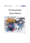
NEC Storage Manager
Data Replication User’s Manual
(Installation and Operation
Guide for Windows)
IS016-5E
© NEC Corporation 2001-2004
No part of the contents of this book may be reproduced or
transmitted in any form without permission of NEC Corporation.
The contents of this book may be modified without notice in the future.
Preface
This manual describes how to use the data replication function provided by NEC Storage DynamicDataReplication
Ver2, NEC Storage RemoteDataReplication Ver2, and NEC Storage ReplicationControl.
The data replication function consists of the replication volume creation function provided in a disk array subsystem
and software to manage and operate it. It utilizes replication volume to make business operation more effective.
Refer to the “NEC Storage Manager Manual Guide” (IS901) for the overview of NEC Storage and the related
manuals.
Also, refer to the “NEC Storage Manager Data Replication User’s Manual (Disaster Recovery System
Installation and Operation Guide)” (IS027) for details of how to use the remote data replication function provided by
NEC Storage RemoteDataReplication/DisasterRecovery and NEC Storage ReplicationControl/DisasterRecovery.
Remarks 1. This manual explains functions implemented by the following program products:
• NEC Storage Manager and NEC Storage BaseProduct
• NEC Storage ReplicationControl
• NEC Storage DynamicDataReplication
• NEC Storage RemoteDataReplication
2. This manual is applicable to the program products of the following versions:
• NEC Storage Manager Ver3.3
• NEC Storage BaseProduct Ver3.3
• NEC Storage ReplicationControl Ver3.3
3. The NEC Storage Manager is referred to as iSM or Storage Manager in the text of this manual. Also,
the NEC Storage series disk array subsystem is referred to as a disk array.
4. The following descriptions in the text of this manual refer to the corresponding products.
Description
Corresponding Product
Storage Manager
NEC Storage Manager
AccessControl
NEC Storage AccessControl
DynamicDataReplication
NEC Storage DynamicDataReplication
PerformanceMonitor
NEC Storage PerformanceMonitor
RemoteDataReplication
NEC Storage RemoteDataReplication
ReplicationControl
NEC Storage ReplicationControl
ReplicationControl SQL Option
NEC Storage ReplicationControl SQL Option
SnapControl
NEC Storage SnapControl
5. The following descriptions in the text of this manual refer to the corresponding manuals.
Description
Corresponding Manual
User's Manual (UNIX)
NEC Storage Manager User's Manual (UNIX) (IS001)
User's Manual
NEC Storage Manager User's Manual (IS004)
ReplicationControl SQL Option User’s
Manual
NEC Storage ReplicationControl SQL Option User’s
Manual (IS006)
Configuration Setting Tool User’s
Manual (GUI)
NEC Storage Manager Configuration Setting Tool User’s
Manual (GUI) (IS007)
Description
Corresponding Manual
Messages Handbook
NEC Storage Manager Messages Handbook (IS010)
Data Replication User’s Manual
(Function Guide)
NEC Storage Manager Data Replication User’s Manual
(Function Guide) (IS015)
Data Replication Command Reference
NEC Storage Manager Data Replication Command
Reference (IS021)
PerformanceMonitor User’s Manual
NEC Storage PerformanceMonitor User’s Manual (IS025)
6. Trademarks and registered trademarks
• Microsoft®, Windows® are registered trademarks or trademarks of Microsoft Corporation in the
United States and other countries.
• HP-UX is a registered trademark of Hewlett-Packard, Co. in the United States.
• UNIX is a registered trademark of The Open Group in the United States and other countries.
• VERITAS, VxVM, VxFS, NetBackup, VERITAS Volume Manager, VERITAS File System, and
VERITAS NetBackup are registered trademarks or trademarks of VERITAS Software Corporation in
the United States and other countries.
• Legato NetWorker is a registered trademark of Legato Systems, Inc. in the United States.
• Sun is a registered trademark of Sun Microsystems, Inc. in the United States and other countries.
• Solaris is a registered trademark of Sun Microsystems, Inc. in the United States.
• Linux is a trademark or registered trademark of Mr. Linus Torvalds in the United States and other
countries.
• AIX is a trademark of IBM Corporation.
• ORACLE is a registered trademark of Oracle Corporation in the United States.
Other product names and company names, etc. are registered trademarks or trademarks of the
associated companies.
7. In this document, matters to which careful attention needs to be paid will be described as follows:
Be sure to observe the contents.
If the indications are ignored and the system is improperly operated, settings which have been already
made might be affected.
Type of Indication
Type
Description
Describes contents which require special attention during operation.
The First Edition in March 2003
The Fifth Edition in November 2004
Contents
Chapter 1
Installation Procedure.......................................................................................................................................1
1.1
Installation Procedure..................................................................................................................................................1
1.2
System Configuration..................................................................................................................................................2
1.2.1
Hardware Configuration ......................................................................................................................................2
1.2.2
Software Configuration .......................................................................................................................................3
1.3
Software Installation....................................................................................................................................................4
1.3.1
Replication Management.....................................................................................................................................4
1.3.2
ReplicationControl ..............................................................................................................................................5
1.4
Disk Array Configuration............................................................................................................................................9
1.4.1
Logical Disk (LD) Selection................................................................................................................................9
1.4.2
Settings of Disk Array Name, Logical Disk Name, and Port Name .................................................................11
1.4.3
Access Control Setting ......................................................................................................................................13
1.4.4
Product License Unlocking ...............................................................................................................................14
1.4.5
Pair Configuration Setting .................................................................................................................................15
1.5
Control Volume Setting.............................................................................................................................................17
1.5.1
Starting the Volume List Display Function.......................................................................................................17
1.5.2
Registering a Control Volume...........................................................................................................................18
1.5.3
Saving Registered Data .....................................................................................................................................19
1.5.4
Reflecting Data to the Volume List...................................................................................................................20
1.6
Volume List Creation ................................................................................................................................................21
1.7
Preparing Volume......................................................................................................................................................22
1.8
Preparation for Operation ..........................................................................................................................................28
Chapter 2
Operation and Maintenance ...........................................................................................................................30
2.1
Operations .................................................................................................................................................................30
2.1.1
Example of Backup Operation ..........................................................................................................................30
2.1.2
Example of Restoring Master Volume Data......................................................................................................38
2.1.3
Example of Using Replication Volumes ...........................................................................................................47
2.1.4
Restarting Business/Backup Server...................................................................................................................55
2.2
Measures for Errors ...................................................................................................................................................59
2.2.1
Error Types ........................................................................................................................................................59
2.2.2
HW Fault Unique to Replication .......................................................................................................................59
2.2.3
Server or Client Fault ........................................................................................................................................61
2.2.4
Abnormal End of ReplicationControl................................................................................................................62
2.2.5
Down of Server Machine Connected to RV ......................................................................................................66
2.2.6
Invalid Product ..................................................................................................................................................67
2.2.7
Information Gathering in the Event of a Fault ..................................................................................................68
Chapter 3
Notes..................................................................................................................................................................69
3.1
Windows System Volumes and Partitions ................................................................................................................69
3.2
File System Selection ................................................................................................................................................71
3.3
Windows System Selection .......................................................................................................................................71
3.4
Disk Signatures..........................................................................................................................................................71
3.5
Copy Control State Selection ....................................................................................................................................71
3.6
RV Access Restriction Setting ..................................................................................................................................72
3.7
Data Replication and Data Consistency ....................................................................................................................73
3.8
Access Right Settings on Volumes............................................................................................................................76
3.9
Control Volume .........................................................................................................................................................76
3.10 Management and Operations of Data Replication.....................................................................................................76
Index
...................................................................................................................................................................................80
i
This page is intentionally left blank.
ii
Chapter 1 Installation Procedure
Chapter 1 Installation Procedure
This chapter describes the system installation procedures showing an example of a tape backup system that uses
the 2000 series disk array subsystem.
11..11 IIn
nssttaallllaattiio
on
nP
Prro
occeed
du
urree
Installation works are outlined below.
For details of the procedures, refer to the associated sections.
1. Determining the system
configuration
y Select necessary hardware
configuration.
y Select necessary software
configuration.
1.2.1 Hardware Configuration
1.2.2 Software Configuration
2. Installing software
y Install/uninstall/update iSM
y Install/uninstall/update
ReplicationControl
1.3.1
Replication Management
1.3.2
ReplicationControl
3. Determining the disk array
configuration
y Select necessary logical disk
(LD) configuration.
y Assign an identification name to
the management target
hardware.
y Set AccessControl according to
the connection state.
y Unlock the product license.
y Configure a pair.
1.4.1
Logical Disk (LD) Selection
1.4.2
Setting of Disk Array Name,
Logical Disk Name, and Port Name
1.4.3
AccessControl Setting
1.4.4 Product License Unlocking
1.4.5 Pair Configuration Setting
4. Setting a control volume
Only when a control volume is
used
1.5
5. Creating the volume list
1.6 Volume List Creation
6. Preparing volumes
1.7 Preparing Volume
7. Preparing the start of operations
1.8 Preparation for Operation
1
Control Volume Setting
Chapter 1 Installation Procedure
11..22 S
Syysstteem
mC
Co
on
nffiig
gu
urraattiio
on
n
11..22..11 H
Haarrddw
waarree C
Coonnffiigguurraattiioonn
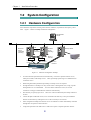
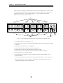
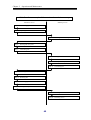
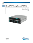
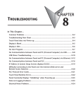
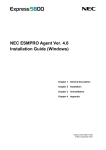
Select hardware components according to the business conditions, requirements, disk capacity, and so
forth.
Figure 1-1 shows an example of hardware configuration.
Management
Server
LAN
LAN
Specific
for Interconnection
Business
Server
(Operated
primarily)
Switch
Figure 1-1
Backup Server
Dir No.1
Port No.1
Switch
Dir No.0
Port No.0
Dir No.1
Port No.0
•
Business
Server
(Standby)
LTO
Dir No.0
Port No.1
Hardware Configuration Example
To utilize the data replication function most efficiently, it is better to separate business servers,
which process tasks, from backup servers. Thus, tape backup operation gives no additional load
to business servers.
•
When doing disk backup instead of tape backup, no backup servers are required.
•
Though the business or backup server may also be used as a management server, using a specific
management server is recommended.
To avoid conflicts with host accesses, use of LAN
connection is strongly recommended for connection with disk array.
•
The disk array accepts any tape drives.
Select one of drives authorized by the backup software to
be used.
•
Connect the path of individual servers, to be connected to the disk array, to the port of different
directors of the disk array, limiting the servers to be accessed by AccessControl.
•
In the configuration example, the business servers are installed in a cluster and mutually connected
through the LAN specific to interconnection.
•
Using data replication in the 4000 series or 3000 series requires a separate replication director.
2
Chapter 1 Installation Procedure
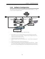
11..22..22 S
Sooffttw
waarree C
Coonnffiigguurraattiioonn
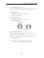
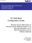
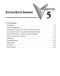
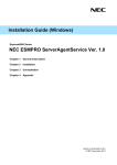
Select software to be used according to the hardware components, operating conditions, etc.
Figure
1-2 shows a software configuration example.
Storage Manager
LAN
Business Server
(Operated
primarily)
Business Server
(Standby)
ReplicationControl
PathManager
Backup Server
LTO
Switch
Dir No.1
Port No.1
Switch
Dir No.1
Port No.0
Dir No.0
Port No.0
ReplicationControl
PathManager
Dir No.0
Port No.1
AccessControl
PerformanceMonitor
DynamicDataReplication
Figure 1-2
•
Software Configuration Example
Because business servers are in cluster configuration, let both the administration and standby
business servers belong to the same domain.
In both the primary and standby business servers,
install the same business application software.
•
Install the backup software in the backup server.
•
Install the management software in the management server.
Install the iSM in the management
server.
•
Install the ReplicationControl in the master and backup servers.
•
Install the DynamicDataReplication and the RemoteDataReplication in the disk array.
From the
server where the iSM is installed, the iSM replication management functions can be executed for
disk arrays where the DynamicDataReplication or the RemoteDataReplication has been installed.
3
Chapter 1 Installation Procedure
11..33 S
So
offttw
waarree IIn
nssttaallllaattiio
on
n
11..33..11 R
Reepplliiccaattiioonn M
Maannaaggeem
meenntt
(1) Operating Environment
Replication Management (Server)
The replication management function is included in the iSM server.
For the operating environment, refer to the “User’s Manual” or “User’s Manual (UNIX)” in
accordance with your OS.
Replication Management (GUI)
The replication management is an expanded function of the iSM client.
For the operating environment, refer to the “User’s Manual” or “User’s Manual (UNIX)” in
accordance with your OS.
(2) Installation
iSM Server Installation
When you install the iSM server, the replication management function of the server is installed.
Refer to the “User’s Manual” or “User’s Manual (UNIX)” in accordance with your OS to install
it.
iSM Server Setting
Create an environment definition file and the environment by referring to the “User’s Manual” or
“User’s Manual (UNIX)” in accordance with your OS.
Replication Management (GUI) Installation
To use the Replication Management of the iSM client, you must install the basic+extended
function.
Refer to the “User’s Manual” or “User’s Manual (UNIX)” in accordance with your OS to install
it.
(3) Software Uninstallation
iSM Server Uninstallation
Refer to the “User’s Manual” or “User’s Manual (UNIX)” in accordance with your OS to uninstall
iSM server.
4
Chapter 1 Installation Procedure
Replication Management (GUI) Uninstallation
Refer to the “User’s Manual” or “User’s Manual (UNIX)” in accordance with your OS to uninstall
the Replication Management (GUI).
(4) Software Update
iSM Server Update
To update the iSM server, uninstall the existing software, and then install the new software.
Replication Management (GUI) Update
To update the iSM client, uninstall the existing software, and then install the new software.
11..33..22 R
ReepplliiccaattiioonnC
Coonnttrrooll
(1) Operating Environment
Operating system
This software operates in the following operating systems.
Microsoft Windows 2000 Advanced Server (SP2 or later)
Microsoft Windows 2000 Server (SP2 or later)
Microsoft Windows Server 2003, Enterprise Edition
Microsoft Windows Server 2003, Standard Edition
Required disk free space
To install the ReplicationControl, at least 35 Mega-bytes of disk free space are required.
Required memory
To use the ReplicationControl, required memory capacity is shown below.
Microsoft Windows 2000 Advanced Server
approx. 2MB or more
Microsoft Windows 2000 Server
approx. 2MB or more
Microsoft Windows Server 2003, Enterprise Edition (64-bit)
approx. 6MB or more
Microsoft Windows Server 2003, Enterprise Edition (32-bit)
approx. 3MB or more
Microsoft Windows Server 2003, Standard Edition
approx. 3MB or more
5
Chapter 1 Installation Procedure
(2) ReplicationControl Software Installation
To install ReplicationControl, follow the procedure below.
(1)
Log on as the Administrator.
(2)
Set the ReplicationControl installation media on CD-ROM drive and execute the following install
program in the CD-ROM drive:
\iSMRC\SETUP.EXE
(3)
Follow the directions of the installer.
The following software components are installed:
•
ReplicationControl
•
Storage Manager Volume List
To use the ReplicationControl, build the logical volumes to be operated on the disk array, set a pair
of volumes under replication control, and then create a Volume List.
Use the iSMvollist command
to create the Volume List.
To use the ReplicationControl through the previously installed job scheduling software or Windows
task scheduler, the services and systems need to restart for recognizing the path names of the
installed execution files.
To install and use both ReplicationControl and SnapControl on the same server, they must be of the
same version.
(3) ReplicationControl Software Uninstallation
To uninstall ReplicationControl, follow the procedure below.
(1)
Log on as the Administrator.
(2)
Check whether the Storage Manager Volume List or ReplicationControl command is running and
whether the Volume List Display screen is open.
Terminate any running command and close any screen.
(3)
Close [Event Viewer] if it is open.
6
Chapter 1 Installation Procedure
(4)
Select the deletion of the following software component by using [Add/Remove Programs] ([Add
or Remove Programs] for Windows Server 2003) in [Control Panel] to start uninstallation:
•
(5)
ReplicationControl
Follow the directions of the uninstaller.
The following software components are uninstalled:
•
ReplicationControl
•
Storage Manager Volume List
If the Storage Manager Volume List or ReplicationControl command is running or the Volume List
Display screen is open, and uninstallation is performed, a message may appear which prompts you to
reboot the operating system.
In this case, be sure to reboot the operating system.
(4) ReplicationControl Software Update
To update the ReplicationControl software, uninstall the existing software, and then install the new
software.
(5) Replication operation option setting
You can set various types of operations when executing a command by using the replication operation
option setting file (iSMrpl.ini).
For details of the replication operation option setting file, refer to the “Data Replication Command
Reference”.
7
Chapter 1 Installation Procedure
ReplicationControl outputs the operation trace (trace log) in the folder iSMrpl\etc\trace under the
folder where ReplicationControl has been installed (\Program Files\NEC\iSMrpl\etc\trace\ by
default) to deal with faults if occur.
In operation trace files, messages output to the standard output, standard error output, event log, and
command trace and the detailed internal information are recorded. These files are used as important
data for analyzing a fault if occurs.
For details of information to be collected in the event of a fault,
refer to 2.2.7 “Information Gathering in the Event of a Fault”.
The amount of the output operation trace (file size) and retention amount and period vary depending
on the command execution frequency and other factors.
You can set these items optionally by
writing the following option parameters:
[TRACELOG] section
RPLLOGFILENUM
Specifies the maximum number of log files to be saved.
When this option parameter is omitted, up to 10 log files are used sequentially.
RPLLOGFILEMAXSIZE
Specifies the maximum size per a log file to be saved in kilobytes.
When this option parameter is omitted, the size of one log file is about 400 kilobytes.
In ReplicationControl Ver2.1 or earlier, log data recorded during the number of days specified by
option parameter RPLLOG was saved in one log file.
This conventional method is not
recommended due to the following reasons:
•
The saved log file becomes larger in proportion to the command execution frequency.
•
When the first command is executed after change-of-day, one day’s log out of the retention
period is deleted.
Therefore, if one day’s log data to be deleted is large, it takes time to
delete it.
Accordingly, if option parameter RPLLOG has been used, it is advisable to change the setting to that
using the above option parameters RPLLOGFILENUM and RPLLOGFILEMAXSIZE for operation.
8
Chapter 1 Installation Procedure
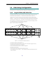
11..44 D
Diisskk A
Arrrraayy C
Co
on
nffiig
gu
urraattiio
on
n
For the disk array to be connected, determine the configuration for using the data replication.
11..44..11 LLooggiiccaall D
Diisskk ((LLD
D)) S
Seelleeccttiioonn
According to the disk capacity necessary for business or operation conditions, determine the logical
disk (LD) and hot spare configurations.
For the 4000 series and the 3000 series, disk array
configurations are executed by maintenance personnel and therefore should be determined before
installation.
To improve the access performance and keep tolerance against physical disk (PD) faults,
assign MV and RV to different ranks.
MV and RV to be paired should have the same LD capacity.
If LD configuration is changed after starting the server, be sure to execute the create/display Volume
List command (iSMvollist -cr) after changing the configuration.
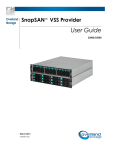
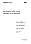
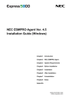
Figure 1-3 shows an example of setting five pairs.
MV
RANK00
RANK01
RANK02
RANK03
RANK04
LD00
LD01
LD02
LD03
LD04
PD00
PD01
PD02
PD03
PD04
PD05
PD06
PD07
PD08
PD09
PD0a
PD0b
PD0c
PD0d
PD0e
PD10
PD11
PD12
PD13
PD14
PD15
PD16
PD17
PD18
PD19
PD1a
PD1b
PD1c
PD1d
PD1e
RANK05
RANK06
RANK07
RANK08
RANK09
LD05
LD06
LD07
LD08
LD09
Spare Disks
RV
Figure 1-3
LD Configuration Example (2000 series)
• The PD group number for PD and RANK is 00.
• One LD is associated with one RANK. (The whole area for one RANK is assigned to one LD.)
• LD00 and LD05 are in RAID5 (4+P) configuration.
• LD01 to LD04 and LD06 to LD09 are in RAID1 configuration.
• Each DE has two spare disks.
• LD00 to LD04 are used for MV and LD05 to LD09 are for RV.
* This configuration is just an example.
Actual configuration should be determined based on your
business conditions.
9
Chapter 1 Installation Procedure
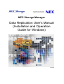
Figure 1-4 shows an example of setting five pairs and one IV on the backup server as a control volume.
A control volume is used when a server issues control I/O to the relevant disk array. For details of a
control volume, refer to 1.5 “Control Volume Setting”, 3.9 “Control Volume”, and the “Data
Replication User’s Manual (Function Guide)”.
MV
RANK00
RANK01
RANK02
RANK03
RANK04
LD00
LD01
LD02
LD03
LD04
PD00
PD01
PD02
PD03
PD04
PD05
PD06
PD07
PD08
PD09
PD0a
PD0b
PD0c
PD0d
PD0e
PD10
PD11
PD12
PD13
PD14
PD15
PD16
PD17
PD18
PD19
PD1a
PD1b
PD1c
PD1d
PD1e
RANK05
RANK06
RANK07
RANK08
RANK09
LD05
LD06
LD07
LD08
LD09
RANK0A
LD0a
Spare Disks
RV
Figure 1-4
Control Volume
LD Configuration Example when a Control Volume Is Used (2000 Series)
• The PD group number for PD and RANK is 00.
• For LD00 to LD09, one LD is associated with one RANK (the whole area for one RANK is assigned
to one LD).
• LD00 and LD05 are in RAID5 (4+P) configuration.
• LD01 to LD04 and LD06 to LD09 are in RAID1 configuration.
• LD00 to LD04 are used for the MV and LD05 to LD09 are for the RV.
• For LD0a, only one small-capacity LD is built with a RANK in RAID0 configuration.
• LD0a is used for an IV as the control volume.
* This configuration is an example.
Actual configuration should be determined based on your
business conditions.
For the disk arrays with pool, you can build a small-capacity logical disk for a control volume. For
details of how to build a control volume, refer to descriptions about building logical disks in the
“Configuration Setting Tool User’s Manual (GUI)”.
10
Chapter 1 Installation Procedure
11..44..22 S
Seettttiinnggss ooff D
Diisskk A
Arrrraayy N
Naam
mee,, LLooggiiccaall
D
Diisskk N
Naam
mee,, aanndd P
Poorrtt N
Naam
mee
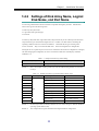
You can assign identification names to hardware components managed by the iSM.
Identification
names can be given to the following items:
• Disk array subsystem name
• Logical disk name (plus OS type)
• Port name
A disk array subsystem name, logical disk name, and port name may be set without special restrictions,
except character types and character length; however, it is better to set these names considering the
operating conditions and server connection conditions.
Determine the OS type according to the
servers connected.
If the LD configuration is changed after
They are set from the iSM client.
starting the servers, separate all pairs on all servers connected to the LD whose configuration is changed,
and, after changing the configuration, be sure to execute the Volume List create/display command
(iSMvollist -cr).
Table 1-1
Example of Disk Array Name Setting
Disk array subsystem
StorageS2130
Remark 1:
Disk array subsystem name
Tokyo_Customer_DataBase
This is an example of setting a disk array name for administrating database of customers
in Tokyo.
Table 1-2
LD No.
OS type
Example of Setting Logical Disk Names and OS Types
Logical disk name
Remarks
00
DB_DATA_MV
MV for DB data file
01
DB_REDO1_MV
MV for DB REDO file 1
02
DB_REDO2_MV
MV for DB REDO file 2
03
DB_CTL_MV
MV for DB control file
DB_ARCHIVE_MV
MV for DB archive file
DB_DATA_RV
RV for DB data file
06
DB_REDO1_RV
RV for DB REDO file 1
07
DB_REDO2_RV
RV for DB REDO file 2
08
DB_CTL_RV
RV for DB control file
09
DB_ARCHIVE_RV
RV for DB archive file
04
05
Remark 1:
WN
Because logical disks are used by Windows servers, set the OS type as WN (the Windows
operating system default value).
Remark 2:
This example shows logical disk names reflecting the database configuration.
11
Chapter 1 Installation Procedure
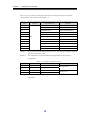
Table 1-3 gives an example of setting logical disk names and OS types for an LD configuration
example when a control volume is used (Figure 1-4).
Table 1-3
Example of Setting Logical Disk Names and OS Types (When a Control Volume Is Used)
LD No.
OS type
Logical disk name
Remarks
00
DB_DATA_MV
MV for DB data file
01
DB_REDO1_MV
MV for DB REDO file 1
02
DB_REDO2_MV
MV for DB REDO file 2
03
DB_CTL_MV
MV for DB control file
04
DB_ARCHIVE_MV
MV for DB archive file
DB_DATA_RV
RV for DB data file
06
DB_REDO1_RV
RV for DB REDO file 1
07
DB_REDO2_RV
RV for DB REDO file 2
08
DB_CTL_RV
RV for DB control file
09
DB_ARCHIVE_RV
RV for DB archive file
0a
BACKUP_CV
Control volume
WN
05
Remark 1:
Because logical disks are used by Windows servers, set the OS type as WN (the Windows
operating system default value).
Remark 2:
This example shows logical disk names reflecting the database and connection
configurations.
Table 1-4
Port No.
Director No.
Example of Setting Port Names
Port name
00
00
DB_SECONDARY
01
00
DB_PRIMARY
00
01
BACKUP_PRIMARY
01
01
BACKUP_SECONDARY
Remark 1:
Server connected
Business server
Backup server
This is an example of setting port names in accordance with the server connection
configuration.
12
Chapter 1 Installation Procedure
11..44..33 A
Acccceessss C
Coonnttrrooll S
Seettttiinngg
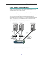
Normally, in a system without clusters, one volume cannot be connected to more than one server to
prevent data inconsistency due to file update from servers.
To prevent erroneous updates to this volume or erroneous changes to disk configuration on the business
servers, the RV must be separated using Access Control, etc. from the business server that uses the MV.
Furthermore, the MV must be separated from the business server that uses the RV, in the same way.
To prevent errors in control volume operation, the control volume must be connected only to a specific
server by using Access Control etc., so that it is not operated or updated from another server.
Before introducing servers, you must determine the server connection modes and design Access Control
settings.
Access Control can be set for individual Ports or WWNs.
Setting for Access Control
requires purchasing the AccessControl.
Figure 1-5 shows an example of Access Control setting for individual Ports.
Business Server
(Operated primarily)
Business Server
(Standby)
MV
Business Server
(Evaluation, Backup)
MV
RV
Dir No.1
Port No.1
Switch
Switch
Access
Control
Access
Control
Dir No.0
Port No.0
Dir No.1
Port No.0
Access
Control
Dir No.0
Port No.1
2000 Series
Figure 1-5
Connection Example in Cluster Configuration
13
Chapter 1 Installation Procedure
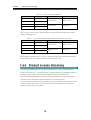
Table 1-5 Access Control Setting Example
Director No.
Port No.
00
00
01
00
00
01
01
01
Access Control settings
Server connected
LD00 to LD04
Business server
LD05 to LD09
Backup server
Table 1-6 gives an Access Control setting example for an LD configuration example when a control
volume is used (Figure 1-4).
Table 1-6 Access Control Setting Example (When a Control Volume is Used)
Director No.
Port No.
00
00
01
00
00
01
01
01
Access Control settings
Server connected
LD00 to LD04
Business server
LD05 to LD09 and
LD0a
Backup server
When setting the configuration, take care not to overlap the ports (MV side) connected to the business
servers and those (RV side) connected to the evaluation and backup servers.
11..44..44 P
Prroodduucctt LLiicceennssee U
Unnlloocckkiinngg
To use the DynamicDataReplication or the RemoteDataReplication, you must unlock the product
license set in the disk array. To unlock the license, you must purchase the corresponding products for
the capacity category equal to or greater than the total physical capacity of the disk array.
When the replication management is executed by starting up the ReplicationControl, these products
check the licenses of the products purchased whether they are purchased properly.
If the total capacity of the physical disk exceeds the product’s specified capacity because physical disks
are added to the disk array system, no additional pairs can be set or canceled (however, replication
operations for the preset pairs are enabled).
14
Chapter 1 Installation Procedure
11..44..55 P
Paaiirr C
Coonnffiigguurraattiioonn S
Seettttiinngg
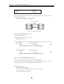
In the basic pair configuration, one RV is connected to one MV. For certain operation conditions, more
than one RV may be connected, but select the basic or parallel configuration for backup operations. The
MV and RV to be paired must have the same LD capacity and OS type.
Disk Array
DynamicDataReplication
MV
RV
Disk Array
RemoteDataReplication
Disk Array
MV
Figure 1-6
RV
Basic Configuration
Disk Array
Synchronized
MV
RV
Backup
(Previous day)
RV
Test Environment
RV
Figure 1-7
Example of Parallel Configuration
15
Chapter 1 Installation Procedure
• An RV of a maximum of four volumes can be set for one PV.
For DynamicDataReplication, an RV of a maximum of three volumes can be set at a time, however.
• An RV can be allocated to a maximum of two disk arrays for one PV.
• The DynamicDataReplication can be set in only one layer in the disk array.
• You cannot set dRV directly for dRV.
• Volumes with different volume capacities cannot be set as a pair.
• Unless the OS type is the same, the pair setting cannot be executed.
Table 1-7
Example of Setting Data Replication
Pair setting
MV
RV
DB_DATA_MV
DB_DATA_RV
DB_REDO1_MV
DB_REDO1_RV
DB_REDO2_MV
DB_REDO2_RV
DB_CTL_MV
DB_CTL_RV
DB_ARCHIVE_MV
DB_ARCHIVE_RV
16
Chapter 1 Installation Procedure
11..55 C
Co
on
nttrro
oll V
Vo
ollu
um
mee S
Seettttiin
ng
g
A control volume is used when a server issues control I/O to the relevant disk array. Select one of the
logical disks connected to each server for each disk array as the volume for issuing I/O to that disk
array and register the volume in the Volume List.
The use of a control volume has the following effects, in particular, in the backup server environment:
• Operation can also be continued even when an RV connected to the server or a link-volume (LV) for
the snapshot function cannot be accessed from the server (operating system) due to a data replication
or snapshot operation.
• From a server that is not connected to an MV to be operated, Replicate and Separate can be executed.
The logical disk which can be operated using the control volume from a server is a logical disk which
is allowed to access that server by the Access Control setting for the disk array or a logical disk
paired with a logical disk which is allowed to access that server.
For details of a control volume, refer to 3.9 “Control Volume” also.
For details of the Volume List Display function, refer to the help of the Volume List Display screen or
the “Data Replication User’s Manual (Function Guide)”.
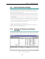
11..55..11 S
Sttaarrttiinngg tthhee V
Voolluum
mee LLiisstt D
Diissppllaayy
FFuunnccttiioonn
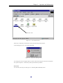
Click the Windows [Start] button and select [Storage Manager Volume List] and [Volume List Display]
from [Programs] ([All Programs] for Windows Server 2003) to start the Volume List Display function.
Figure 1-8
Volume List Display Screen
17
Chapter 1 Installation Procedure
Then, select [Define Control Volume] in [Operation] in the Volume List Display screen to open the
Define Control Volume screen.
Figure 1-9
Define Control Volume Screen
“Selected Volume List”
Lists already registered control volumes.
“Candidate Volume List”
Lists candidate logical disks that can be registered as a control volume.
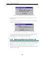
11..55..22 R
Reeggiisstteerriinngg aa C
Coonnttrrooll V
Voolluum
mee
A control volume is used when a server issues control I/O to the relevant disk array. You can select
one logical disk for each disk array as a control volume.
Prepare a volume such as IV with which the
server can properly issue I/O to the disk array.
Do not select an RV or a link-volume (LV) for the snapshot function as a control volume because it
may enter the Not Ready state during operation.
18
Chapter 1 Installation Procedure
(1)
Select a logical disk you want to use as a control volume from “Candidate Volume List”.
(2)
Click the [Add] button.
(3)
The selected logical disk is registered in “Selected Volume List”.
Figure 1-10
Registering a Control Volume
11..55..33 S
Saavviinngg R
Reeggiisstteerreedd D
Daattaa
Click the [OK] button on the Define Control Volume screen.
A confirmation message appears asking
if you want to save definition information.
Figure 1-11
The definition of control volume: Saving Confirmation Screen
Clicking the [Yes] button for the message saves definition information and displays a termination
message.
Clicking the [No] button displays the Define Control Volume screen again.
19
Chapter 1 Installation Procedure
Figure 1-12
The definition of control volume: Termination Message Screen
Clicking the [OK] button closes the Define Control Volume screen and displays the Volume List
Display screen again.
Clicking the [Cancel] button in the Define Control Volume screen displays a confirmation message
asking if you want to cancel the definition.
Figure 1-13
The definition of control volume: Cancel Confirmation Screen
Clicking the [Yes] button for the message cancels saving of the definition information.
The Define
Control Volume screen is closed and the Volume List Display screen appears again.
Clicking the [No] button displays the Define Control Volume screen again.
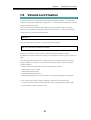
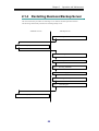
11..55..44 R
Reefflleeccttiinngg D
Daattaa ttoo tthhee V
Voolluum
mee LLiisstt
Select [Create/Update Volume List] from [File] in the Volume List Display screen to create or update
the Volume List file, reflect the saved registration data of the control volume to the Volume List, and
register it.
When the Volume List file has been created or updated, the Volume List Display screen is
automatically refreshed.
Confirm that “Control” is displayed for “Volume Definition” of the logical
disk selected as a control volume.
20
Chapter 1 Installation Procedure
11..66 V
Vo
ollu
um
mee L
Liisstt C
Crreeaattiio
on
n
Creation of Volume List is required before using replication operation command. A Volume List is
created by the iSMvollist command with an argument -cr.
Execute iSMvollist command by a user that
belongs to Administrators group.
When you have already performed [Create/Update Volume List] using the Volume List Display
function (screen operation) according to the instructions described in 1.5, “Control Volume Setting”,
you do not have to perform the following operation.
iSMvollist -cr
Upon successful creation of Volume List, the following message appears:
iSM11701: Volume list is created successfully.
If creation of a Volume List fails, execution of replication operation command is disabled.
Troubleshoot in accordance with an error message or with operation error tracing, create a Volume List
again.
Even under operation with replication, a Volume List must be created again in the following cases.
Failing in updating of Volume List may result in data inconsistency upon execution of replication
operation command.
• Change of disk array settings (disk array name, logical disk name, format)
• Setting/Change of Access Control
• Adding/change/deleting of disk
• Adding/change/deleting of partition
• Adding/change/deleting of drive name on partition, and of drive path mounted on NTFS folder
To use a control volume, before creating or updating a Volume List, check the following:
• A control volume has been selected and registered in advance using the Define Control Volume
function from the Volume List Display screen.
21
Chapter 1 Installation Procedure
11..77 P
Prreep
paarriin
ng
gV
Vo
ollu
um
mee
When using a volume for the first time for replication operation or changing the MV partition size,
execute the steps given below for the target volume.
In data replication operation using ReplicationControl Ver3.2 or later, if NOTREADY is specified
for the UMOUNT_RVACC parameter in the replication operation option setting file, the mount
point (drive letter or NTFS folder name) is automatically deleted and the automatic mount becomes
unavailable at RV unmounting. On Windows 2000, the RV access restriction is changed to Not
Ready to suppress automatic volume mounting by Windows.
default that the automatic mounting is not suppressed.
However, this parameter is set to the
It is recommended that NOTREADY be
specified for this parameter to suppress automatic RV mounting for operation.
For details of this parameter, refer to Chapter 3 “Operation Settings” in the “Data Replication
Command Reference”.
On Windows Server 2003, use the MOUNTVOL command provided by the operating system to
suppress automatic volume mounting before operation.
To suppress automatic volume mounting, execute the MOUNTVOL command with specifying the N
option as follows:
MOUNTVOL
Step 1.
/N
Creating MV partition
Using [Disk Management] (Windows), create partitions on a volume to be used for MV.
In a recommended partition configuration, one physical disk contains one partition.
Step 2.
Creating file system
Create a file system on a disk of MV where a partition has been created and assign a drive letter to the
file system created.
22
Chapter 1 Installation Procedure
Step 3.
Checking RV volume
In Windows 2000, using [Disk Management] (Windows), check that the disk to be used as RV is in an
unassigned area.
If signature is not found, execute “Signature Disk” here.
If RV has partitions,
delete them and place the area in unassigned state.
On Windows Server 2003, use [Disk Management] (Windows) to create partitions on the disk to be
used as the RV in advance so that the disk has the same partition configuration as the MV.
At this
time, do not assign any drive letter.
Step 4.
Creating Volume List
On each host on MV and RV sides, create a Volume List using the iSMvollist command of the
ReplicationControl.
Create the Volume List as follows:
iSMvollist –cr
When creating the Volume List has succeeded, the following message will appear:
iSMvollist: Info:
iSM11701: Volume list is created successfully.
Output the Volume List information to the vollist_data.txt.
iSMvollist -a > vollist_data.txt
* After changing the logical disk name using the iSM, you must update the Volume List.
* To use a control volume, before creating a Volume List, select and register the control volume using
the Define Control Volume function from the Volume List Display screen.
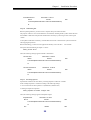
Step 5.
Saving disk signature
Execute the following command for each host on MV and RV sides and save the signature for the
replication target disk.
iSMrc_signature -read -all
Step 6.
Backing up disk signature
Back up the disk signature saved in step 5 above, by executing the following command on each host on
MV and RV sides:
iSMrc_signature -export file-name –all
* For the file-name, specify an arbitrary file name.
* This backup is performed to enable the disk signature to be restored to its saved status when an
incorrect disk signature has been written due to an operation error.
23
Chapter 1 Installation Procedure
Step 7.
Setting pair
Use the Replication Management (GUI) for setting a pair.
executed by using the iSMrc_pair command.
In addition, the pair setting can also be
By checking the vollist_data.txt that stores the Volume
List information created in step 4 and the volume displayed by the Replication Management, determine
the target disk for replication and set a pair.
For pair setting, note the following:
• The MV and RV disk capacities must be the same.
• The MV and RV disks must be the basic disks.
• A volume format must be “WN” or “A2”.
• In the recommended configuration, MV contains one partition for one volume.
When executing Replicate for RV for the first time, RV must be in the following state:
• In Windows 2000, RV must be in unassigned area.
• On Windows Server 2003, the disk to be used as the RV has the same partition configuration as the
MV.
Step 8.
The drive letter is unassigned.
Copying disk
Execute Replicate for the pair set in step 7 above. In this example, execute Replicate for logical disk
name dev001.
iSMrc_replicate -mv dev001 -mvflg ld -rv dev002 -rvflg ld
Then, the following start message appears and copying from MV to RV begins.
Replicate Start
2001/02/21 11:06:13
MV:10
dev001
WN
\\?\Volume{ce49f299-614e-11d5-b1df-009027520bce}\
G:
RV:-
dev002
WN
Step 9.
Flushing MV file system
Flush the MV file system and write the file system buffer data, not yet written, to the disk.
that the MV volume has been assigned to G:.
iSMrc_flush -drv G:
Then, the following message appears and flushing occurs.
Flush Start
2001/02/21 11:08:14
disk10
dev001
\\?\Volume{822575dd-63d9-11d5-b1e0-009027520bce}\
G:
24
WN
Assume
Chapter 1 Installation Procedure
Flush Normal End
2001/02/21 11:08:14
disk10
dev001
WN
\\?\Volume{822575dd-63d9-11d5-b1e0-009027520bce}\
G:
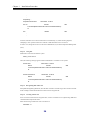
Step 10.
Unmounting MV
Before separating MV/RV, you must create a complete static point of the MV data.
The purpose of this is to write out all data that is not reflected, including the file system control data and
the metadata to disk and to keep the MV and RV data consistency by restricting accesses to the logical
volume.
To keep MV and RV data consistency, unmount MV and clear the volume and file system associations
after stopping the operation.
Before unmounting, you must close all applications that may access the drive.
Also read the
description about unmounting in Chapter 3 “Notes”.
iSMrc_umount -drv G:
Then, the following message appears and MV is unmounted.
Umount Start
2001/02/21 11:08:20
disk10
dev001
WN
\\?\Volume{822575dd-63d9-11d5-b1e0-009027520bce}\
G:
Umount Normal End
2001/02/21 11:08:20
disk10
dev001
WN
\\?\Volume{822575dd-63d9-11d5-b1e0-009027520bce}\
G:
Step 11.
Executing Separate
Separate MV and RV from each other by executing Separate to make RV available.
In this example, Separate is executed according to the following settings:
• Access restrictions for RV separated: rw (Read/Write) (default value)
• Waiting for Separate completion
iSMrc_separate -mv dev001 -mvflg ld –wait
Then, the following message appears and Separate begins.
Separate Start
MV:10
2001/02/21 11:08:21
dev001
WN
\\?\Volume{822575dd-63d9-11d5-b1e0-009027520bce}\
G:
RV:-
dev002
25
WN
Chapter 1 Installation Procedure
Separating…
Separate Normal End
2001/02/21 11:08:21
MV:10
dev001
WN
\\?\Volume{822575dd-63d9-11d5-b1e0-009027520bce}\
G:
RV:-
dev002
WN
Note that, if the RV access restriction has been set to Read Only (ro) when executing Separate,
attempting a write operation to that drive with the volume mounted causes a write error.
In such a case, change the RV access restriction to Read/Write (rw) from the Replication Management
(GUI).
Step 12.
Using MV
Mount MV to associate MV and file system.
iSMrc_mount -drv G:
Then, the following message appears and the mounted MV is available as a file system.
Mount Start
2001/02/21 11:08:22
disk10
dev001
WN
\\?\Volume{822575dd-63d9-11d5-b1e0-009027520bce}\
G:
Mount Normal End
2001/02/21 11:08:22
disk10
dev001
WN
\\?\Volume{822575dd-63d9-11d5-b1e0-009027520bce}\
G:
Step 13.
Recognizing disk on RV side
Start [Disk Management] (Windows) from the host on the RV side and assign a drive name to the disk.
In this example, assume that the RV drive letter has been assigned to H:.
Step 14.
Creating Volume List
Since a new drive name has been assigned to RV, creation of Volume List is required using iSMvollist
command of the ReplicationControl.
Enter the following command to create a Volume List.
iSMvollist –cr
26
Chapter 1 Installation Procedure
Upon successful creation of Volume List, the following message appears:
iSMvollist: Info:
iSM11701: Volume list is created successfully.
Output the Volume List data into the vollist_data.txt.
iSMvollist -a > vollist_data.txt
* If a logical disk name has been changed using the iSM, the Volume List must be updated.
* To use a control volume, before creating a Volume List, select and register the control volume using
the Define Control Volume function from the Volume List Display screen.
Step 15.
Researching mount point volume name
A mount point volume name used for operation must be researched.
Enter “MOUNTVOL /L” on DOS prompt.
MOUNTVOL /L
Then, the list of volumes available on system is displayed as follows:
\\?\Volume{e2464851-8089-11d2-8803-806d6172696f}\
F:\
\\?\Volume{e2464852-8089-11d2-8803-806d6172696f}\
G:\
\\?\Volume{e2464850-8089-11d2-8803-806d6172696f}\
H:\
A mount point volume name is required for replication operation for operations such as backup, etc.
Take a memo of the mount point volume names, which are displayed in the mount point volume name
list, to use in the operation.
Now, the volume is ready.
27
Chapter 1 Installation Procedure
11..88 P
Prreep
paarraattiio
on
n ffo
orr O
Op
peerraattiio
on
n
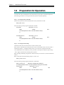
To operate the system in the Replicate state, take the following steps and re-synchronize (Replicate).
The following procedures are not required when the systems are operated separately.
Step 1.
Executing RV file system flush
Flush RV file system and write the unwritten data in file system buffer onto disk.
iSMrc_flush –drv H:
Then, the following message appears and the data is flushed.
Flush Start
2001/02/21 11:21:13
disk11
dev002
WN
\\?\Volume{37d84cca-2507-11d5-a0f7-00004c714491}\
H:
Flush Normal End
2001/02/21 11:21:13
disk11
dev002
WN
\\?\Volume{37d84cca-2507-11d5-a0f7-00004c714491}\
H:
Step 2.
Executing RV unmounting
Unmount RV and cancel association between volume and file system.
When the RV is unmounted, the mount point (drive letter or NTFS folder name) set for the volume is
automatically deleted.
On Windows 2000, the RV access restriction is changed to Not Ready.
* Set NOTREADY for the UMOUNT_RVACC parameter in the replication operation option setting
file to suppress automatic RV mounting before operation.
When executing unmounting, all application software, that may access the drive, must be terminated in
advance.
Refer to descriptions about unmounting Chapter 3 “Notes” also.
iSMrc_umount –drv H:
Then, the following message appears and the RV is unmounted:
iSMrc_umount: Info:
iSM13221: Resetting drive letter (H:)
(\\?\Volume{37d84cca-2507-11d5-a0f7-00004c714491}\) has succeeded.
Umount Start
2001/02/21 11:21:14
disk11
dev002
\\?\Volume{37d84cca-2507-11d5-a0f7-00004c714491}\
H:
28
WN
Chapter 1 Installation Procedure
iSMrc_umount: Info:
iSM13221: Resetting drive letter (H:)
(\\?\Volume{37d84cca-2507-11d5-a0f7-00004c714491}\) has succeeded.
Umount Normal End
2001/02/21 11:21:14
disk11
dev002
WN
\\?\Volume{37d84cca-2507-11d5-a0f7-00004c714491}\
H:
Step 3.
Executing Replicate
Execute Replicate and re-synchronize (Replicate).
iSMrc_replicate -mv dev001 -mvflg ld -rv dev002 -rvflg ld
Then , the following message appears and data copying from MV to RV is started:
Replicate Start
MV:10
2001/02/21 11:21:15
dev001
WN
\\?\Volume{ce49f299-614e-11d5-b1df-009027520bce}\
G:
RV:-
dev002
-
29
WN
Chapter 2 Operation and Maintenance
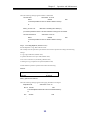
Chapter 2 Operation and Maintenance
This chapter describes an example of operation using the Data Replication function, the operation procedure for
replication, and the trouble-shooting for faults that may occur during operations.
22..11 O
Op
peerraattiio
on
nss
22..11..11 E
Exxaam
mppllee ooff B
Baacckkuupp O
Oppeerraattiioonn
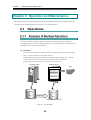
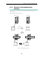
This section describes an example of backup operation by using the Data Replication function.
Although the text describes the commands in input order, the command execution is automated by job
scheduling software on the system built actually.
(1) Overview
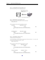
Data of the master volume (MV) used in operation is replicated to the replication volume (RV).
Then, it is saved to the tape by using backup software.
Assume that the backup environment has the configuration shown in Figure 2-1. Now, the
volumes have been set as a pair, and operation has started in the Separated state.
In this example, the MV drive letter is G: and the RV drive letter is H:.
Business Server
Backup Server
Tape
ARCserve
BackUp Exec
NetBackup
MV
Disk Copy
RV
Master Volume (MV)
Replication Volume (RV)
Figure 2-1
Online Backup
30
Chapter 2 Operation and Maintenance
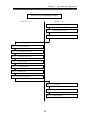
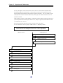
Work flow of the backup example
<Business server>
<Backup server>
Step 1.
Step 4.
Executing Replicate
Step 5.
Terminating applications
Step 6.
Flushing MV file system
Step 7.
Unmounting MV
Step 8.
Executing Separate
Step 9.
Mounting MV
Terminating applications
Step 2.
Flushing RV file system
Step 3.
Unmounting RV
Step 10. Restarting applications
Step 11. Mounting RV
Step 12. Restarting applications
Step 13. Executing Backup
31
Chapter 2 Operation and Maintenance
(2) Operation procedure
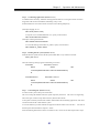
Step 1.
Terminating applications (backup server)
To maintain data consistency, terminate or halt applications and specified services that are accessing the
volume concerned.
If shared folders are used on the volume concerned, cancel sharing temporarily.
If application or service has not been halted or terminated, or accesses to shared folder exist,
unmounting in step 3 fails.
(Example) Halting service
NET STOP (service name)
When halting a service “ESMCommonService”, specify as follows:
NET STOP ESMCommonService
Step 2.
Flushing RV file system (backup server)
Flush the RV file system and write the file system buffer data, not yet written, to the disk.
iSMrc_flush –drv H:
Thus, the following message appears and flushing occurs.
Flush Start
2001/02/21 12:27:01
disk11
dev002
WN
\\?\Volume{37d84cca-2507-11d5-a0f7-00004c714491}\
H:
Flush Normal End
2001/02/21 12:27:01
disk11
dev002
WN
\\?\Volume{37d84cca-2507-11d5-a0f7-00004c714491}\
H:
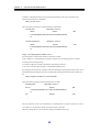
Step 3.
Unmounting RV (backup server)
Unmount RV and cancel the volume and file system associations.
When the RV is unmounted, the mount point (drive letter or NTFS folder name) set for the volume is
automatically deleted.
On Windows 2000, the RV access restriction is changed to Not Ready.
* Set NOTREADY for the UMOUNT_RVACC parameter in the replication operation option setting
file to suppress automatic RV mounting before operation.
Before unmounting, you must close all applications that may access the drive.
description about unmounting in Chapter 3 “Notes”.
iSMrc_umount –drv H:
32
Also read the
Chapter 2 Operation and Maintenance
Then, the following message appears and RV is unmounted.
Umount Start
2001/02/21 12:27:02
disk11
dev002
WN
\\?\Volume{37d84cca-2507-11d5-a0f7-00004c714491}\
H:
iSMrc_umount: Info:
iSM13221: Resetting drive letter (H:)
(\\?\Volume{37d84cca-2507-11d5-a0f7-00004c714491}\) has succeeded.
Umount Normal End
2001/02/21 12:27:02
disk11
dev002
WN
\\?\Volume{37d84cca-2507-11d5-a0f7-00004c714491}\
H:
Step 4.
Executing Replicate (business server)
Execute Replicate to copy data from MV to RV.
This example uses the replication operation file and executes replication according to the following
settings.
• Copy range: Difference (default value)
• Update reflection to RV: Sync mode (default value)
• RV access restriction: nr (Not Ready) (default value)
• Waiting for copy completion not specified (default value)
Assume that the replication operation file contains the following:
disks.txt
# Type:MV
Type:RV
ld:dev001
ld:dev002
iSMrc_replicate -file disks.txt
Then, the following message appears and copying from MV to RV begins.
Replicate Start
2001/02/21 12:27:10
MV:10 dev001
WN
\\?\Volume{822575dd-63d9-11d5-b1e0-009027520bce}\
G:
RV:-
dev002
WN
-
33
Chapter 2 Operation and Maintenance
Step 5.
Terminating applications (business server)
To maintain data consistency, terminate or halt applications and specified services that are accessing the
target volume.
If a shared folder is used on the target volume, cancel the sharing temporarily.
If applications and services have not been halted or terminated, or a shared folder is accessed, the
unmounting operation in step 7 will fail.
(Example) Halting service
NET STOP (service name)
When halting a service “ESMCommonService”, specify as follows:
NET STOP ESMCommonService
(Example) Cancel the sharing of the shared folder.
NET SHARE share_name /delete
When canceling sharing of shared folder mv_folder1, specify as follows:
NET SHARE mv_folder1 /delete
Step 6.
Flushing MV file system (business server)
Flush the file system of MV and write data in buffer of the file system which has not been written to the
disk.
iSMrc_flush -drv G:
Then, the following message is displayed and flush is executed.
Flush Start
2001/02/21 12:23:14
disk10
dev001
WN
\\?\Volume{822575dd-63d9-11d5-b1e0-009027520bce}\
G:
Flush Normal End
2001/02/21 12:23:14
disk10
dev001
\\?\Volume{822575dd-63d9-11d5-b1e0-009027520bce}\
G:
34
WN
Chapter 2 Operation and Maintenance
Step 7.
Unmounting MV (business server)
You must create a perfect static point of MV data.
This is for writing the metadata of the file system completely to the disk. This is also for suppressing
I/O to the logical volume to keep data consistency of MV and RV.
To keep data consistency of MV and RV, unmount MV after stopping operation, and cancel association
between the volume and file system.
To execute unmount, you must quit all application software which access the drive.
Also refer to the
description about unmount in Chapter 3 “Notes”.
If MV unmounting failed and no means of avoidance exists, wait for 60 seconds and proceed to step 8.
In addition, although separating is allowed without unmounting in this step, unmounting upon
replication and restoration is mandatory.
iSMrc_umount -drv G:
Then, the following message is displayed and MV is unmounted.
Umount Start
2001/02/21 12:23:15
disk10
dev001
WN
\\?\Volume{822575dd-63d9-11d5-b1e0-009027520bce}\
G:
Umount Normal End
2001/02/21 12:23:15
disk10
dev001
WN
\\?\Volume{822575dd-63d9-11d5-b1e0-009027520bce}\
G:
Step 8.
Executing Separate (business server)
Execute Separate to separate MV and RV to make RV available, and resume applications.
This example uses the replication file and separates MV and RV according to the following settings.
• Copy range: Difference (default value)
• Update reflection to RV: Sync mode (default value)
• Access restrictions for RV after Separate: rw (Read/Write) (default value)
• Specify the wait for Separate completion
iSMrc_separate -file disks.txt -wait
35
Chapter 2 Operation and Maintenance
Then, the following message is displayed and MV is separated.
Separate Start
2001/02/21 12:23:16
MV:10 dev001
WN
\\?\Volume{ce49f299-614e-11d5-b1df-009027520bce}\
G:
RV:-
dev002
WN
Separating.....
Separate Normal End
MV:10
2001/02/21 12:23:16
dev001
WN
\\?\Volume{ce49f299-614e-11d5-b1df-009027520bce}\
G:
RV:-
dev002
WN
If access restrictions for RV is set to Read Only (ro) when Separate is executed, a write error occurs if
you execute a write operation to the drive on which the volume is mounted.
In this case, change the access restrictions for RV to Read/Write Permit (rw) from the Replication
Management (GUI).
Step 9.
Mounting MV (business server)
Use MV again on applications.
To associate MV and the file system, mount MV.
iSMrc_mount -drv G:
Then, the following message is displayed.
Mount Start
MV is mounted and can be used as a file system.
2001/02/21 12:23:17
disk10
dev001
WN
\\?\Volume{822575dd-63d9-11d5-b1e0-009027520bce}\
G:
Mount Normal End
2001/02/21 12:23:17
disk10
dev001
\\?\Volume{822575dd-63d9-11d5-b1e0-009027520bce}\
G:
36
WN
Chapter 2 Operation and Maintenance
Step 10.
Restarting applications (business server)
Restart the applications closed in Step 5.
If services were halted in step 5, restart the services by the following procedures. If services were not
halted in step 5, executing of the following is not required.
(Example) Starting service
NET START (service name)
To start the service “ESMCommonService”, specify as shown below.
NET START ESMCommonService
If sharing of a folder was cancelled in step 5, specify sharing again.
If sharing was not cancelled in
step 5, executing of the following is not required.
(Example) Sharing of a folder
NET SHARE share_name=drive_letter: path
To enable the sharing of the folder mv_folder1, specify as shown below.
NET SHARE mv_folder1=G:\mv_folder1
Step 11.
Mounting RV (backup server)
To associate RV and the file system, mount RV.
When the RV is mounted with the mount point (drive letter or NTFS folder name) and target mount
point volume name specified, the mount point (drive letter or NTFS folder name) is automatically set
again.
On Windows 2000, the RV is released from the Not Ready state.
iSMrc_mount –drv H: -mvol \\?\Volume{37d84cca-2507-11d5-a0f7-00004c714491}\
Then, the following message is displayed.
Mount Start
RV is mounted and can be used as a file system.
2001/02/21 12:26:14
disk11
dev002
WN
\\?\Volume{37d84cca-2507-11d5-a0f7-00004c714491}\
H:
iSMrc_mount: Info:
iSM13220: Setting drive letter (H:)
(\\?\Volume{37d84cca-2507-11d5-a0f7-00004c714491}\) has succeeded.
Mount Normal End
2001/02/21 12:26:14
disk11
dev002
\\?\Volume{37d84cca-2507-11d5-a0f7-00004c714491}\
H:
Use RV for backup on applications.
37
WN
Chapter 2 Operation and Maintenance
Step 12.
Restarting applications (backup server)
Start the applications and services terminated in step 1.
For the procedures to start services and share
the folder, refer to step 10.
Step 13.
Executing backup (backup server)
Use backup software to back up the data copied to RV to the tape.
22..11..22 E
Exxaam
mppllee ooff R
Reessttoorriinngg M
Maasstteerr V
Voolluum
mee
D
Daattaa
This section describes procedures of restoring master volume (MV) data.
(1) Data restoration without use of replication function
When restoring data via network or restoring data on master volume (MV) directly from backup
data on the tape, execute data restoration in the procedure specific to the backup software.
LAN
Business Server
Backup Server
Tape
Backup Software
ARCserve
BackUp Exec
Restore data on master
volume (MV) via
NetBackup
network.
Restore master volume
(MV) data directly using
backup data on tape.
MV
RV
Master Volume
Replications Volume
Figure 2-2
An Example of Data Restoration without Use of Replication Function
38
Chapter 2 Operation and Maintenance
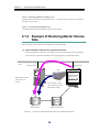
(2) Data restoration with use of replication function
The following describes the procedures of completely restoring data using backup tape, upon
failure of data file.
The procedures assume that MV data file has physical or logical failure, and
the tape contains backup data previously retrieved.
Business Server
Backup Server
Backup Software
Tape
ARCserve
BackUp Exec
NetBackup
MV
RV
D:\
D:\
Failure on Master
Volume
Replication Volume
Figure 2-3
An Example of Data Restoration with Use of Replication Function
LD names of MV/RV are dev001 and dev002 respectively, and both are assigned to D drive in
respective hosts.
39
Chapter 2 Operation and Maintenance
Work flow for an example of the master volume data recovery
<Business server>
Step 1.
Terminating applications
Step 2.
Repairing MV
Step 4.
Flushing MV file system
Step 5.
Unmounting MV
Step 9.
<Backup server>
Step 3.
Executing Restore from tape
Step 6.
Halting service
Step 7.
Flushing RV file system
Step 8.
Unmounting RV
Executing Restore
Step 10. Mounting MV
Step 11. Restarting applications
Step 12. Waiting for Separated state
Step 13. Mounting RV
Step 14. Restarting service
40
Chapter 2 Operation and Maintenance
Step 1.
Terminating applications (business server)
Terminate or halt applications and specified services that are accessing the volume where a fault has
occurred.
If a shared folder is used on the target volume, cancel the sharing temporarily.
(Example) Halting service
NET STOP (service name)
When halting a service “ESMCommonService”, specify as follows:
NET STOP ESMCommonService
(Example) Canceling sharing of folder
NET SHARE share_name /delete
When canceling the sharing of the folder mv_folder1, specify as follows:
NET SHARE mv_folder1 /delete
Terminate application.
RV
MV
Figure 2-4
Step 2.
Terminating Application
Repairing MV (business server)
When MV was rebuilt to recover from a hardware fault, or when a new logical volume was created,
signature the disk by using [Disk Management] (Windows).
Then, set a partition, create a file system by carrying out format, and reset the drive letter.
For the
partition, file system and drive letter, use settings previously specified before the fault occurred.
Also, re-create a volume list and update it.
iSMvollist –cr
When the volume list has been successfully updated, the following message appears:
iSMvollist: info:
iSM11701: Volume list is created successfully.
41
Chapter 2 Operation and Maintenance
Step 3.
Executing Restore from tape (backup server)
Restore data from the tape to RV, using backup software.
Backup Software such as
ARCserve, BackUp Exec,
NetBackup, etc.
Tape
RV
Figure 2-5
Step 4.
Restoring Backup Data to RV
Flushing MV file system (business server)
Flush the MV file system and discard data in the file system buffer.
iSMrc_flush -drv D:
Then, the following message appears and flushing is executed.
Flush Start
2001/02/21 12:23:03
disk10
dev001
WN
\\?\Volume{822575dd-63d9-11d5-b1e0-009027520bce}\
D:
Flush Normal End
2001/02/21 12:23:04
disk10
dev001
WN
\\?\Volume{822575dd-63d9-11d5-b1e0-009027520bce}\
D:
Step 5.
Unmounting MV (business server)
Unmount MV before executing Restore.
To execute unmounting, you must terminate all applications which access the drive.
Also, refer to the
description about unmounting in Chapter 3 “Notes”.
iSMrc_umount -drv D:
Then, the following message appears and unmounting is executed.
Umount Start
2001/02/21 12:23:15
disk10
dev001
WN
\\?\Volume{822575dd-63d9-11d5-b1e0-009027520bce}\
D:
Umount Normal End
2001/02/21 12:23:15
disk10
dev001
\\?\Volume{822575dd-63d9-11d5-b1e0-009027520bce}\
42
WN
Chapter 2 Operation and Maintenance
D:
If normal unmounting fails, execute unmounting again by specifying the -force option.
iSMrc_umount -drv D: -force
Step 6.
Halting service (backup server)
Terminate or halt applications and services that may prevent RV from being unmounted.
If
applications and services have not been halted or terminated, the unmounting operation in step 8 will
fail.
(Example) Halting service
NET STOP (service name)
When halting a service “ESMCommonService”, specify as follows:
NET STOP ESMCommonService
Step 7.
Flushing RV file system (backup server)
Flush the RV file system and write the unwritten data in file system buffer onto disk.
iSMrc_flush –drv D:
Step 8.
Unmounting RV (backup server)
Unmount RV and cancel association between the volume and the file system.
When the RV is unmounted, the mount point (drive letter or NTFS folder name) set for the volume is
automatically deleted.
On Windows 2000, the RV access restriction is changed to Not Ready.
* Set NOTREADY for the UMOUNT_RVACC parameter in the replication operation option setting
file to suppress automatic RV mounting before operation.
When executing unmounting, all application software, that is supposed to access the drive, must be
terminated in advance.
Refer to descriptions about unmounting Chapter 3 “Notes” also.
iSMrc_umount –drv D:
Step 9.
Executing Restore (business server)
Execute Restore on the MV volume.
In this example, it is assumed that the replication operation file is used and the data is restored
according to the following settings:
• RV operation mode: RV protection
• RV access restriction: nr (Not Ready) (default value)
• Waiting for copy completion not specified (default value)
It is also assumed that the replication operation file contains the following:
disks.txt
43
Chapter 2 Operation and Maintenance
# Type:MV
Type:RV
ld:dev001
ld:dev002
When Restore with RV protection specified is executed, Separate is automatically executed after
Restore has been completed.
iSMrc_restore -file disks.txt -mode protect
Execute Restoration.
MV
RV
Figure 2-6
Step 10.
Executing Restoration
Mounting MV (business server)
Use MV again on applications.
Mount MV to associate it with a file system.
iSMrc_mount -drv D:
Then, the following message appears, and MV is mounted allowing it to be used as a file system.
Mount Start
2001/02/21 12:23:17
disk10
dev001
WN
\\?\Volume{822575dd-63d9-11d5-b1e0-009027520bce}\
D:
Mount Normal End
2001/02/21 12:23:17
disk10
dev001
WN
\\?\Volume{822575dd-63d9-11d5-b1e0-009027520bce}\
D:
Step 11.
Restarting applications (business server)
Restart the applications and services that have been terminated in Step 1.
If services have been halted in step 1, restart the services by the following procedures.
were not halted in step 1, it is not necessary to execute the following.
(Example) Starting service
NET START (service name)
To start the service “ESMCommonService”, specify as shown below.
NET START ESMCommonService
44
If services
Chapter 2 Operation and Maintenance
If sharing of the folder was cancelled in step 1, specify the sharing again.
If sharing was not cancelled
in step 1, it is not necessary to execute the following.
(Example) Sharing of shared folder
NET SHARE share_name=drive_letter: path
To enable the sharing of the folder mv_folder1, specify as shown below.
NET SHARE mv_folder1=G:\mv_folder1
Step 12.
Waiting for Separated state (business server)
When Restore with RV protection specified has been executed, the system waits for the automatic
Separate.
iSMrc_wait -file disks.txt -cond sep
Waiting for the Separated State.
RV
MV
Figure 2-7
Step 13.
Waiting for the Separated State
Mounting RV (backup server)
Mount RV to associate it with a file system.
When the RV is mounted with the mount point (drive letter or NTFS folder name) and target mount
point volume name specified, the mount point (drive letter or NTFS folder name) is automatically set
again.
On Windows 2000, the RV is released from the Not Ready state.
iSMrc_mount –drv D: -mvol \\?\Volume{37d84cca-2507-11d5-a0f7-00004c714491}\
Then, the following message appears, and RV is mounted allowing it to be used as a file system.
Mount Start
2001/02/21 12:26:14
disk11
dev002
WN
\\?\Volume{37d84cca-2507-11d5-a0f7-00004c714491}\
D:
iSMrc_mount: Info:
iSM13220: Setting drive letter (D:) (\\?\Volume{37d84cca-2507-
11d5-a0f7-00004c714491}\) has succeeded.
Mount Normal End
2001/02/21 12:26:14
disk11
dev002
\\?\Volume{37d84cca-2507-11d5-a0f7-00004c714491}\
D:
45
WN
Chapter 2 Operation and Maintenance
Use RV again as a backup volume.
Step 14.
Restarting service (backup server)
Resume the applications and services that have been terminated in step 6.
If the services have been halted in step 6, restart the services by the following procedure.
services were not halted in step 6, it is not necessary to execute the following.
(Example) Restarting service
NET START (service name)
To restart the service “ESMCommonService”, specify as shown below.
NET START ESMCommonService
46
If the
Chapter 2 Operation and Maintenance
22..11..33 E
Exxaam
mppllee ooff U
Ussiinngg R
Reepplliiccaattiioonn
V
Voolluum
meess
This section describes how to build the environment same as that used for actual operations, using a
replication volume.
Figure 2-8 shows the replication volume structure.
Backup Server
Business Server
Disk Copy
MV
RV
Master Volume
Replication Volume
Use replication volume.
Actual Operations
MV
RV
Separate
Master Volume
Replication Volume
Figure 2-8
Building Replication Volume
47
Chapter 2 Operation and Maintenance
By using the Separate function which enables the use of RV also in the middle of separation while
reflecting the difference of MV and RV, it is not necessary to wait for the copy operation to finish,
thereby reducing the time duration when the master operations are halted.
Also, it is possible to refer
to the replication volume for the latest data, thereby reducing the time duration when the server-side
operations are halted.
In this example, replication volume building is explained by assuming that the volumes have been set as
a pair and operation has started using the business server, the pair is separated, and the MV drive letter
is G and the RV drive letter is H.
Before starting replication operations, prepare the target volumes beforehand.
For more information on how to prepare volumes, refer to 1.7 “Preparing Volume”.
Work flow for an example of the use of the replication
<Business server>
Step 4.
Executing Replicate
Step 5.
Terminating applications
Step 6.
Flushing MV file system
Step 7.
Unmounting MV
Step 8.
Executing Separate
Step 9.
Mounting MV
<Backup server>
48
Step 1.
Terminating applications
Step 2.
Flushing RV file system
Step 3.
Unmounting RV
Chapter 2 Operation and Maintenance
Step 10. Restarting applications
Step 11. Mounting RV
Step 12. Restarting applications
The following describes the procedure for executing replication control for the RV that is can be used
as a file system through the prepared volumes:
Step 1.
Terminating applications (backup server)
To maintain data consistency, terminate or halt applications and specified services that area accessing
the volume concerned.
(Example) Stopping service
NET STOP (service name)
To stop the service “ESMCommonService”, specify as shown below.
NET STOP ESMCommonService
Step 2.
Flushing RV file system (backup server)
Flush the file system of RV and write data in buffer of the file system which has not been written to the
disk.
iSMrc_flush –drv H:
Then, the following message is displayed and flush is executed.
Flush Start
2001/02/21 11:21:13
disk11
dev002
WN
\\?\Volume{37d84cca-2507-11d5-a0f7-00004c714491}\
H:
Flush Normal End
2001/02/21 11:21:13
disk11
dev002
WN
\\?\Volume{37d84cca-2507-11d5-a0f7-00004c714491}\
H:
Step 3.
Unmounting RV (backup server)
Unmount RV and cancel association between the volume and the file system.
When the RV is unmounted, the mount point (drive letter or NTFS folder name) set for the volume is
automatically deleted.
On Windows 2000, the RV access restriction is changed to Not Ready.
* Set NOTREADY for the UMOUNT_RVACC parameter in the replication operation option setting
file to suppress automatic RV mounting before operation.
49
Chapter 2 Operation and Maintenance
When executing unmounting, all application software, that may access the drive, must be terminated in
advance.
Refer to descriptions about unmounting Chapter 3 “Notes” also.
iSMrc_umount –drv H:
Then, the following message appears and RV is unmounted:
Umount Start
2001/02/21 11:21:14
disk11
dev002
WN
\\?\Volume{37d84cca-2507-11d5-a0f7-00004c714491}\
H:
iSMrc_umount: Info:
iSM13221: Resetting drive letter (H:)
(\\?\Volume{37d84cca-2507-11d5-a0f7-00004c714491}\) has succeeded.
Umount Normal End
2001/02/21 11:21:14
disk11
dev002
WN
\\?\Volume{37d84cca-2507-11d5-a0f7-00004c714491}\
H:
Step 4.
Executing Replicate (business server)
Execute Replicate for the pair that needs replication.
In this example, it is assumed that the replication operation file is used and replication is executed
according to the following setting:
• Copy range: Difference (default value)
• Update reflection to RV: Sync mode
• RV access restriction: nr (Not Ready) (default value)
• Waiting for copy completion: Not specified (default value)
It is also assumed that the replication operation file contains the following:
disks.txt
# Type:MV
Type:RV
ld:dev001
ld:dev002
iSMrc_replicate -file disks.txt
Then, the following message appears and the data copy from MV to RV is started:
Replicate Start
2001/02/21 12:21:15
MV:10
dev001
WN
\\?\Volume{822575dd-63d9-11d5-b1e0-009027520bce}\
G:
RV:-
dev002
-
50
WN
Chapter 2 Operation and Maintenance
Step 5.
Terminating applications (business server)
To maintain data consistency, terminate or halt applications that are accessing the volume concerned.
If application has not been terminated, unmounting in step 7 fails.
If shared folders are used on the volume concerned, cancel sharing temporarily.
(Example) Stopping service
NET STOP (service name)
To stop the service “ESMCommonService”, specify as shown below.
NET STOP ESMCommonService
(Example) Canceling shared folder
NET SHARE shared name/delete
To cancel the sharing of the folder mv_folder1, specify as shown below.
NET SHARE mv_folder1 /delete
Step 6.
Flushing MV file system (business server)
Flush the MV file system and write the file system buffer data, not yet written, to the disk.
iSMrc_flush -drv G:
Then, the following message appears and flushing is executed.
Flush Start
2001/02/21 12:23:14
disk10
dev001
WN
\\?\Volume{822575dd-63d9-11d5-b1e0-009027520bce}\
G:
Flush Normal End
2001/02/21 12:23:14
disk10
dev001
WN
\\?\Volume{822575dd-63d9-11d5-b1e0-009027520bce}\
G:
Step 7.
Unmounting MV (business server)
You must create a perfect static point of MV data.
This is for writing the metadata of the file system completely to the disk. This is also for suppressing
I/O to the logical volume to keep data consistency between MV and RV.
To keep data consistency between MV and RV, unmount MV after terminating applications, and cancel
association between the volume and file system.
To execute unmount, you must terminate all application software which access the drive. Also refer to
the description about unmount in Chapter 3 “Notes”.
If MV unmounting failed and no means of avoidance exists, wait for 60 seconds and proceed to step 8.
51
Chapter 2 Operation and Maintenance
In addition, although separating is allowed without unmounting in this step, unmounting upon
replication and restoration is mandatory.
iSMrc_umount -drv G:
Then, the following message is displayed and MV is unmounted.
Umount Start
2001/02/21 12:23:15
disk10
dev001
WN
\\?\Volume{822575dd-63d9-11d5-b1e0-009027520bce}\
G:
Umount Normal End
2001/02/21 12:23:15
disk10
dev001
WN
\\?\Volume{822575dd-63d9-11d5-b1e0-009027520bce}\
G:
Step 8.
Executing Separate (business server)
Execute Separate to separate MV and RV to make RV available.
In this example, it is assumed that the replication operation file is used and Separate is executed
according to the following settings:
• The time to make RV available: immediately after Separate execution
• RV access restrictions after Separate: rw (Read/Write)(default value)
By setting the time to make RV available to the time immediately after Separate execution, RV can be
used immediately after Separate has been executed while reflecting the difference between MV and
RV.
iSMrc_separate -file disks.txt -rvuse immediate
Then, the following message appears and Separate is executed.
Separate Start
MV:10
2001/02/21 12:23:16
dev001
WN
\\?\Volume{ce49f299-614e-11d5-b1df-009027520bce}\
G:
RV:-
dev002
WN
If access restrictions for RV is set to Read Only (ro) when Separate is executed, a write error occurs if
you execute a write operation to the drive after the volume is mounted.
Therefore, change the RV access restriction setting to Read/Write Permit (rw).
52
Chapter 2 Operation and Maintenance
Step 9.
Mounting MV (business server)
To associate MV and the file system, mount MV.
iSMrc_mount -drv G:
Then, the following message is displayed.
Mount Start
MV is mounted and can be used as a file system.
2001/02/21 12:23:17
disk10
dev001
WN
\\?\Volume{822575dd-63d9-11d5-b1e0-009027520bce}\
G:
Mount Normal End
2001/02/21 12:23:17
disk10
dev001
WN
\\?\Volume{822575dd-63d9-11d5-b1e0-009027520bce}\
G:
Step 10.
Restarting applications (business server)
Reuse the applications and shared folder, that is terminated and canceled in step 5.
If service has been halted in step 5, restart the service with the following procedure.
If service has not
been halted in step 5, the following step is not required.
(Example) Starting service
NET START (service name)
To start the service “ESMCommonService”, specify as shown below.
NET START ESMCommonService
If sharing of a folder was cancelled in step 5, specify sharing again.
If sharing was not cancelled in
step 5, executing of the following is not required.
(Example) Sharing of shared folder
NET SHARE Share_name=drive_letter: path
To enable the sharing of the shared folder mv_folder1, specify as shown below.
NET SHARE mv_folder1=G:\mv_folder1
Step 11.
Mounting RV (backup server)
Mount RV to associate it with a file system.
When the RV is mounted with the mount point (drive letter or NTFS folder name) and target mount
point volume name specified, the mount point (drive letter or NTFS folder name) is automatically set
again.
On Windows 2000, the RV is released from the Not Ready state.
iSMrc_mount –drv H: -mvol \\?\Volume{37d84cca-2507-11d5-a0f7-00004c714491}\
Then, the following message appears, and RV is mounted, allowing it to be used as a file system.
53
Chapter 2 Operation and Maintenance
Mount Start
2001/02/21 12:26:14
disk11
dev002
WN
\\?\Volume{37d84cca-2507-11d5-a0f7-00004c714491}\
H:
iSMrc_mount: Info:
iSM13220: Setting drive letter (H:) (\\?\Volume{37d84cca-2507-
11d5-a0f7-00004c714491}\) has succeeded.
Mount Normal End
2001/02/21 12:26:14
disk11
dev002
WN
\\?\Volume{37d84cca-2507-11d5-a0f7-00004c714491}\
H:
Use RV again for backup on applications.
Step 12.
Restarting applications (backup server)
Restart the applications terminated in Step 1 above.
If service has been halted in step 1, restart the service with the following procedure.
been halted in step 1, the following step is not required.
(Example) Restarting service
NET START (service name)
To restart the service “ESMCommonService”, specify as shown below.
NET START ESMCommonService
54
If service has not
Chapter 2 Operation and Maintenance
22..11..44 R
Reessttaarrttiinngg B
Buussiinneessss//B
Baacckkuupp S
Seerrvveerr
This section describes procedures for restarting a server that uses the data replication function.
The following describes the procedures for restarting backup server.
<Business server>
Step 2.
Step 9.
<Backup server>
Step 1.
Shutting down server
Step 3.
Restarting server
Step 4.
Scanning disks
Step 5.
Executing CHKDSK
Step 6.
Terminating applications
Step 7.
Flushing RV file system
Step 8.
Unmounting RV
Executing Separate
Executing Replicate
55
Chapter 2 Operation and Maintenance
Step 1.
Shutting down server (backup server)
Shut down a server that is connected with RV.
Step 2.
Executing Separate (business server)
Execute Separate on RV that is not separated and connected with the backup server.
If the RV is
separated already, separation is not required.
This example uses the replication file for the execution according to the following settings.
• Access restriction on RV after separation: rw (Read/Write)
• Separation completion wait specified
Assume that the replication operation file is used and Separate is executed under the following
conditions:
disks.txt
# Type:MV
Type:RV
ld:dev001
ld:dev002
iSMrc_separate -file disks.txt -wait
Step 3.
Restarting server (backup server)
After verifying completion of separation, restart the backup server.
Step 4.
Scanning disks (backup server)
Scan the disks to make the server recognize the disks in the Not Ready state and volumes which cannot
be mounted.
On Windows 2000, disks may be left in the Not Ready state by unmounting using the iSMrc_umount
command.
In this case, release the disks from the Not Ready state and make the server recognize the
disks.
iSMrc_scan
The operation displays the following message and scans disks.
This operation may take several tens of seconds to complete.
Scan Start
2001/02/21 11:19:13
Scan Normal End
2001/02/21 11:20:26
Use the MOUNTVOL command to check that all target disks can be recognized from the operating
system.
On Windows Server 2003, use the MOUNTVOL command to disable automatic volume mounting:
MOUNTVOL /N
56
Chapter 2 Operation and Maintenance
Step 5.
Executing CHKDSK (backup server)
In step 2, separation was executed without specifying a static point. Execute CHKDSK /F to remove
inconsistency in file system.
CHKDSK H: /F
Step 6.
Terminating applications (backup server)
To maintain data consistency, terminate or halt applications and specified services.
(Example) Terminating service
NET STOP (service name)
To stop the service “ESMCommonService”, specify as shown below.
NET STOP ESMCommonService
Step 7.
Flushing RV file system (backup server)
Flush RV file system and write the unwritten data in file system buffer onto disk.
iSMrc_flush –drv H:
The operation displays the following message and flushes the data.
Flush Start
2001/02/21 11:21:13
disk11
dev002
WN
\\?\Volume{37d84cca-2507-11d5-a0f7-00004c714491}\
H:
Flush Normal End
2001/02/21 11:21:13
disk11
dev002
WN
\\?\Volume{37d84cca-2507-11d5-a0f7-00004c714491}\
H:
Step 8.
Unmounting RV (backup server)
Unmount RV and cancel association between volume and file system.
When the RV is unmounted, the mount point (drive letter or NTFS folder name) set for the volume is
automatically deleted.
On Windows 2000, the RV access restriction is changed to Not Ready.
* Set NOTREADY for the UMOUNT_RVACC parameter in the replication operation option setting
file to suppress automatic RV mounting before operation.
When executing unmounting, all application software, that may access the drive, must be terminated in
advance.
Refer to descriptions about unmounting Chapter 3 “Notes” also.
iSMrc_umount –drv H:
57
Chapter 2 Operation and Maintenance
Then, the following message appears and RV is unmounted.
Umount Start
2001/02/21 11:21:14
disk11
dev002
WN
\\?\Volume{37d84cca-2507-11d5-a0f7-00004c714491}\
H:
iSMrc_umount: Info:
iSM13221: Resetting drive letter (H:)
(\\?\Volume{37d84cca-2507-11d5-a0f7-00004c714491}\) has succeeded.
Umount Normal End
2001/02/21 11:21:14
disk11
dev002
WN
\\?\Volume{37d84cca-2507-11d5-a0f7-00004c714491}\
H:
Step 9.
Executing Replicate (business server)
Execute replicate for the pair that needs replication.
In this example, it is assumed that the replication operation file is used and replication is executed
according to the following settings:
• Copy area: Differences (default value)
• Reflecting update on MV: Synchronization mode (default value)
• Access restriction on RV: nr (Not Ready) (default value)
• Completion wait not specified (default value)
iSMrc_replicate -file disks.txt
Then, the following message appears and the data copy from MV to RV is started:
Replicate Start
MV:10
2001/02/21 12:21:15
dev001
WN
\\?\Volume{ce49f299-614e-11d5-b1df-009027520bce}\
G:
RV:-
dev002
Execute usual backup procedures after the processes above.
58
WN
Chapter 2 Operation and Maintenance
22..22 M
Meeaassu
urreess ffo
orr E
Errrro
orrss
22..22..11 E
Errrroorr TTyyppeess
Data replication errors can be categorized as follows:
(1)
HW fault unique to replication
(2)
iSM Server or client fault
(3)
ReplicationControl abnormal end
(4)
Down of server machine connected to RV
(5)
Invalid product
22..22..22 H
HW
W FFaauulltt U
Unniiqquuee ttoo R
Reepplliiccaattiioonn
The data replication function realized by HW may cause errors given below, in addition to ordinary
HW faults.
These errors can be checked from the iSM Client screen. These errors may abnormally
stop ReplicationControl commands.
(1) Copy Fault
Detecting a copy fault
If copy operation between MV and RV is not executed normally due to a connection failure
between them, a transition to the following states may occur depending on the timing and type of
the failure.
•
Separate state due to a failure (failure separation)
•
Suspend state due to a failure (abnormal suspend)
If a transition occurs to one of the states above, you can use Replication Screen to check the status
of the copy fault (Figure 2-9).
59
Chapter 2 Operation and Maintenance
Figure 2-9
An Example of the Copy Fault Occurrence Screen
Operations after recovering from a copy fault
For information on operation to recover the state of the pair where the copy fault occurred to the
normal state after removing the cause of the copy fault, refer to 3.3.20 “Display Copy Fault List”
in the “Data Replication User’s Manual (Function Guide)”.
(2) Link fault
Detecting a link fault
A link fault occurs due to a cable fault between disk arrays or a fault of Replication Director.
If it occurs during Replication, it may cause a copy fault.
If a link fault occurs, you can use the Replication Screen to check it.
60
Chapter 2 Operation and Maintenance
Figure 2-10
An Example of the Link Failure Occurrence Screen
Operations after recovering from a link fault
After you remove the cause of the link fault, check that the state of the path is normal in this
screen.
If a copy fault occurs due to this fault, refer to 3.3.20 “Display Copy Fault List” in the “Data
Replication User’s Manual (Function Guide)” to recover from the failure.
22..22..33 S
Seerrvveerr oorr C
Clliieenntt FFaauulltt
(1) Communication failures
If communication with the iSM Server fails, the following message is displayed and Replication
Screen terminates.
Take necessary actions referring to the “User’s Manual”.
Figure 2-11
Communication Failure Message Screen
61
Chapter 2 Operation and Maintenance
22..22..44 A
Abbnnoorrm
maall E
Enndd ooff R
ReepplliiccaattiioonnC
Coonnttrrooll
ReplicationControl outputs error contents to the standard output, standard error output, event log,
command trace, or operation trace when an error has occurred.
The standard output, standard error output, event log, or command trace records the messages described
in the “Messages Handbook”. Take necessary actions depending on the message.
The command trace is output in the folder iSMrpl\etc under the folder where ReplicationControl has
been installed (\Program Files\NEC\iSMrpl\etc\ by default) with a file name beginning with
“iSM_Log”.
Check the contents using a text editor.
The operation trace records the messages output to the standard output, standard error output, event log,
or command trace and the detailed internal information.
If a fault occurs and you want to request the
provider to investigate the fault, you must collect the operation trace. For details of how to collect
information when a fault occurs, refer to 2.2.7, “Information Gathering in the Event of a Fault”.
(1) Abnormal End of iSMrc_umount Command
If a program running on server is referring to a volume concerned, the command outputs the
following message and terminates abnormally.
iSM13609: Access of specified disk was refused.
For obtaining a static point in file system, the program in question must be researched and halt of
the program must be specified in operation procedures.
* For researching an application that accesses to the drive, Sysinternals’s free software is useful.
Refer to descriptions about unmounting Chapter 3 “Notes” also.
If iSMrc_umount still terminates abnormally after halting all applications and services accessing
to a disk in question, take the following actions:
- When iSMrc_umount command terminates abnormally on business server Step 1.
Terminate application (business server)
Halt applications and services with programs running on server, that are referring to a volume
concerned.
After verifying halt of applications and services, execute iSMrc_umount again.
If
iSMrc_umount terminates normally, execution of the following processes is not required.
If the command still terminates abnormally after this process, take the following step.
Step 2.
60-second waiting (business server)
If MV unmounting failed wait for 60 seconds.
If it is separated in the 60-second wait time, files smaller than 600 byte and files being updated
may not be reflected on RV.
If separation was executed without unmounting, execute CHKDSK
/F upon mounting on RV.
This process allows separation without unmounting.
62
Chapter 2 Operation and Maintenance
- When iSMrc_umount command terminates abnormally on business server Step 1.
Terminate application (backup server)
Halt applications and services with programs running on server, that are referring to a volume
concerned.
Step 2.
After verifying halt of applications and services, execute iSMrc_umount again.
Executing CHKDSK (backup server)
Execute the CHKDSK to maintain a static point of the file system.
Execution example on CHKDSK:
In CHKDSK, specify a mount point volume name omitting “\” at the end.
CHKDSK \\?\Volume{37d84cca-2507-11d5-a0f7-00004c714491} /F /X
* Refer to CHKDSK help before using the CHKDSK command.
Step 3.
Executing iSMrc_umount (backup server)
After completion of CHKDSK, execute iSMrc_umount again.
If the command still terminates abnormally after this process, take the following step.
Step 4.
Restarting backup server
If CHKDSK/F/X fails, restart the backup server by taking the steps in 2.1.4 “Restarting
Business/Backup Server”.
(2) Abnormal end of the iSMrc_restore command
The state, in which setting the drive letter of MV or mounting the MV in the NTFS folder is
canceled, remains in the following case:
During control under which the MV is unmounted at start of Restore, a server fails, or re-setting
the drive letter of the MV or remounting the MV in the NTFS folder fails for some reason.
If re-setting the drive letter for MV or mounting the MV in the NTFS folder fails, the
iSMrc_restore command outputs either of the following messages:
iSM13634: Failed to set drive letter (drive letter:).
iSM13634: Failed to set mount point (NTFS folder path name).
In this case, recovery (e.g., re-setting of the drive letter or remounting of MV into the NTFS
folder) is necessary for restarting operation. The following describes the recovery procedure:
Step 1.
Collecting volume information
If a server has failed, restart it by executing the procedure in 2.1.4 “Restarting Business/Backup
Server”, starting with Step 2.
Collect the volume information (drive letter and mount point volume name) of the MV that was to
be restored. To collect the volume information of the MV, confirm the following message that is
output to the event log or the batch file execution result:
63
Chapter 2 Operation and Maintenance
iSM13224: MV is restored.
Volume Name: mount point volume name
Mount Point: drive letter or NTFS folder path name
Step 2.
Re-setting the drive letter and remounting MV into the NTFS folder
Start [Disk Management].
According to the collected MV volume information (drive letter and
mount point volume name), operate the volume with [Change Drive Letter and Path] to set the
drive letter and mount the MV with the NTFS folder path name specified.
You can also set the drive letter and mount the MV in the NTFS folder by entering the
MOUNTVOL command through the command prompt.
Example of setting a drive letter
To set the drive letter H for the volume under the mount point volume name
“\\?\Volume{37d84cca-2507-11d5-a0f7-00004c714491}\”, specify as shown below.
MOUNTVOL H: \\?\Volume{37d84cca-2507-11d5-a0f7-00004c714491}\
Step 3.
Repairing the file system
The file system may contain conflicting data.
Execute CHKDSK /F to repair the file system.
Example of executing CHKDSK
Omit the “\” at the end of the mount point volume name in specifying it for CHKDSK.
CHKDSK \\?\Volume{37d84cca-2507-11d5-a0f7-00004c714491} /F
* For notes on executing CHKDSK, refer to the help information of CHKDSK.
(3) Illegal File System on RV Connection Server
Replication operation without unmounting RV may result in illegal file system.
If RV file system has become illegal, restore the system by the restoration procedures.
Research method
•
When an error occurs in using the ReplicationControl or an access program.
If the ReplicationControl command outputs the following error message or errors meaning
“destroyed file or disk”, the RV file system is illegal.
Restore the file system by the
restoration procedures.
iSM13639: Specified path is not normal status.
•
If backup server is allowed to access RV during replication or unmounting operation
* Normally, access to RV during replication operation or unmounting operation with
automatic mounting suppressed on Windows 2000 is not allowed because RV is in the Not
Ready state.
Try access to RV volume during replication or unmounting operation from My Computer.
64
Chapter 2 Operation and Maintenance
Access to “H:”
Figure 2-12
My Computer Screen
When RV is “Not Ready” and cannot be accessed, the following message appears.
If this dialog appears, RV is successfully unmounted.
Figure 2-13
Media Error Message Screen
If a message above does not appear and access to the volume of the target RV is allowed, an illegal RV
file system is suspected.
Restore the system by the restoration procedures.
Restoration
For restoration, take step 2 according to 2.1.4 “Restarting Business/Backup Server”.
65
Chapter 2 Operation and Maintenance
22..22..55 D
Doow
wnn ooff S
Seerrvveerr M
Maacchhiinnee C
Coonnnneecctteedd
ttoo R
RV
V
When the server connected to RV has gone down, RV may not be recognized from the Operating
System after restarting the server. This may occur when the server is restarted while the RV is placed
in the Not Ready (unavailable for read or write) state by executing Replicate or Restore or while it is
unmounted by the iSMrc_umount command and is in the Not Ready state on Windows 2000.
case, you must make the Operating System recognize RV.
In this
This section describes how to do this.
(1) If server is done down
Step 1.
Executing Separate
For all RV pairs, in Replicate/Restore state, execute Separate.
If ordinary Separate fails, execute Forced Separate.
Step 2.
Starting server
Start the server that has been down.
Step 3.
Recognizing the RV again
Execute the following command to scan the disks and make the server recognize the disks in the
Not Ready state and the volumes which cannot be mounted.
On Windows 2000, disks may be left in the Not Ready state by unmounting using the
iSMrc_umount command. In this case, release the disks from the Not Ready state and make the
server recognize the disks.
This operation may take several tens of seconds to complete.
iSMrc_scan
Use the MOUNTVOL command to check that all target disks can be recognized from the
operating system.
On Windows Server 2003, use the MOUNTVOL command to disable automatic volume
mounting:
MOUNTVOL /N
Step 4.
Recovering to normal operation
Execute Replicate referring to 2.1 “Operations”.
* When the partition contains an error, execute Replicate referring to 1.7 “Preparing Volume”.
66
Chapter 2 Operation and Maintenance
(2) If server is restarting
Execute the procedure below so that the OS to recognize the RV again.
Step 1.
Executing Separate
For all RV pairs in Replicate/Restore state, execute Separate.
If ordinary Separate fails, execute Forced Separate.
Step 2.
Recognizing RV again
Execute the following command to scan the disks and make the server recognize the disks in the
Not Ready state and the volumes which cannot be mounted.
On Windows 2000, disks may be left in the Not Ready state by unmounting using the
iSMrc_umount command. In this case, release the disks from the Not Ready state and make the
server recognize the disks.
This operation may take tens of seconds to complete.
iSMrc_scan
Use the MOUNTVOL command to check that all target disks can be recognized from the
operating system.
On Windows Server 2003, use the MOUNTVOL command to disable automatic volume
mounting:
MOUNTVOL /N
Step 3.
Recovering to normal operation
Execute Replicate referring to 2.1 “Operations”
* When the partition contains an error, execute Replicate referring to 1.7 “Preparing Volume”.
22..22..66 IInnvvaalliidd P
Prroodduucctt
If the product for replication (refer to 1.4.4 “Product License Unlocking”) has not been purchased or if
it does not match the total physical capacity of the disk array, the Replication does not function
properly.
If the products are not purchased properly, the icon on the Replication screen (Tree view) changes to
indicate missing products or products not purchased.
For purchased products, check disk array Properties in the State Monitoring screen.
67
Chapter 2 Operation and Maintenance
22..22..77 IInnffoorrm
maattiioonn G
Gaatthheerriinngg iinn tthhee E
Evveenntt ooff
aa FFaauulltt
When an error whose reason is unknown has occurred and you want to request the provider to
investigate the error, you must collect information required for error analysis.
(1) For Replication Management error
Collect the necessary information referring to the “User’s Manual”.
(2) For ReplicationControl error
Follow the steps below to execute the command and collect the operation trace and other fault
information at a time.
A disk for storing fault information must have at least about 4 MB of unused space. The total
size of fault information files differs depending on the system status, so it may exceed 4 MB.
It
is advisable to allocate an unused space of enough size.
(1) Log on as a member in the Administrator group.
(2) Click the Windows [Start] button and select [Storage Manager Volume List] and [Difficulty
Information Gather] from [Programs] ([All Programs] for Windows Server 2003).
If you want to change the storage destination directory and execute the command, specify a
directory on the relevant server. Do not specify any directory on another server connected
via the network.
(3) Confirm that the iSMvolgather directory is created under the installation directory when the
storage destination directory is not changed or under the specified directory when it is
changed, and obtain the files under that directory.
68
Chapter 3 Notes
Chapter 3 Notes
This chapter describes some notes regarding management and operations of Data Replication.
33..11 W
Wiin
nd
do
ow
wss S
Syysstteem
mV
Vo
ollu
um
meess aan
nd
d
P
Paarrttiittiio
on
nss
Data replication handles target volumes for individual disk array’s logical disk. If replication
operation is executed for a volume that contains more than one partition or logical volume in one
logical disk, for a volume consisting of more than one partition or logical volume and for a volume such
as a dynamic disk, data consistency is not guaranteed for certain operations.
Table 3-1 gives
functional scopes for disk types.
Table 3-1
Disk type
Basic disk
Dynamic disk
Available Volume Types
Volume type
Availability
Primary partition (MBR format)
√
Primary partition (GPT format)
-
Logical volume on expanded partition
√
Simple volume
-
Span volume
-
Stripe volume
-
Mirror volume
-
RAID-5 volume
-
√: Recommended configuration
-: Operation inhibited
On Windows Server 2003, use the MOUNTVOL command provided by the operating system to
disable automatic volume mounting before operation.
To disable automatic volume mounting, specify the N option and execute the MOUNTVOL
command as follows:
MOUNTVOL
/N
69
Chapter 3 Notes
Data replication operation using a logical disk containing multiple partitions or logical volumes is
not recommended.
In ReplicationControl, when the volume to be operated is recognized from the server (operating
system) and can be accessed, and if the volume contains multiple partitions or logical volumes
obtained by the disk configuration information of the target volume, operation is not allowed
(default).
You can perform operation for a logical disk containing multiple partitions or logical volumes by
changing settings in the replication operation option setting file. In this case, be extremely careful
about operation.
For details of the replication operation option setting file, refer to the “Data Replication Command
Reference”.
Disk containing multiple partitions or logical volumes
When a drive letter is specified to execute replication operation for a logical disk containing multiple
partitions or logical volumes, all partitions or logical volumes on the logical disk become the target for
the replication operation.
This is because replication operation is executed for an individual logical
disk.
Figure 3-1 shows an example where each of MV and RV consist of multiple partitions, with drives E:
and F: assigned to MV and drives J: and K: assigned to RV.
Assume that you execute replication by
specifying drive E: as MV, attempting to replicate only the data of drive E: of MV to drive J: of RV.
As the result, data of drive F: is also replicated, overwriting RV drive K: with data of MV drive F:. That
is, data of RV drive K: will be lost.
At this time, unless the disk association with the file system of RV
drive K: is cleared, the file system of drive K: will be placed in inconsistent state.
Figure 3-1
E:
J:
F:
K:
MV
RV
Replicating a Disk Containing Multiple Partitions
To avoid this type of trouble, data replication operations are not recommended for a logical disk
containing multiple partitions or logical volumes.
Take care when you execute operations to a logical
disk containing multiple partitions or logical volumes.
70
Chapter 3 Notes
33..22 F
Fiillee S
Syysstteem
mS
Seelleeccttiio
on
n
You can configure a file system for the target MV and RV volumes for replication operations.
addition, these volumes may be used as RAW devices for ORACLE, etc.
In
The target MV and RV
paired for replication operations must have the same type of partitions and file systems.
If these rules
are not observed, data consistency is not guaranteed.
33..33 W
Wiin
nd
do
ow
wss S
Syysstteem
mS
Seelleeccttiio
on
n
As business servers and backup servers using each of MV and RV volume, Windows 2000 servers and
Windows Server 2003 servers cannot be used together.
Use the MV and RV volumes from the same
Windows operating system. If the MV and RV volumes are used from different Windows operating
systems, data consistency cannot be guaranteed.
33..44 D
Diisskk S
Siig
gn
naattu
urreess
A disk signature is the disk identifier that is written in the header block of the disk when it is referenced
for the first time by [Disk Management] (Windows).
The Windows system does not allow using two
or more disks with the same signature in the same system.
For a volume in the Windows system (OS type “WN” or “A2”), the data replication function restores
the original identifier before copying so that the MV and RV do not have the same identifier when
separating the pair.
33..55 C
Co
op
pyy C
Co
on
nttrro
oll S
Sttaattee S
Seelleeccttiio
on
n
There are three copy control states available when executing Replicate or Restore. When applying data
replication to the backup system, it is necessary to take backup by Separate and immediately resolve the
difference between MV and RV when re-synchronizing. For that purpose, select Sync mode.
When Restore with RV protection specified is executed, the updated data of the MV is not reflected into
the RV. Therefore, copy control by using Foreground Copy (Sync Mode or Semi Sync Mode) and
Background Copy has no effect.
There are the following copy control states as shown in Table 3-2.
71
Chapter 3 Notes
Table 3-2 Copy Control States
Copy Control State
Foreground Copy
Sub-State
Sync Mode
Copy State
• Updates MV and RV synchronously.
After completing the MV
and RV update, informs the host of I/O completion.
• For DDR, copy is done only to the cache.
Therefore, this copy
mode little lowers the performance.
• For RDR, performance lowered by this copy mode is in
proportion to the distance between the disk arrays.
Semi Sync Mode
• Updates to MV and RV are done asynchronously up to a certain
data size.
When the MV update completes and data not
reflected to RV is within the predetermined data size, informs
the host of I/O completion without waiting for the RV update
and immediately reflects the update to the RV. If the data not
reflected to RV has exceeded the predetermined size, the
operation is the same as Foreground Copy (sync mode).
• This can be set only for RDR.
Background Copy
-
• Updates to MV and RV are done asynchronously. After
completing the MV update, informs the host of the I/O
completion without waiting for the RV update. The RV update
is accumulated as differential information and reflected to RV
asynchronously with the MV update.
The interval of copy to
RV can be set for individual disk arrays (background copy level).
33..66 R
RV
VA
Acccceessss R
Reessttrriiccttiio
on
nS
Seettttiin
ng
g
Because RV is replicated within the disk array independently of the server, its replicated contents are
completely match with the contents of MV.
When the Windows system is used, MV and RV cannot
be used at the same time within the same system, because the volume identification information used by
the Windows system to identify the volume is also the same. Data replication gives no access
restrictions for MV, allowing Read/Write (RW) at any time.
For RV, set the RV access restriction in
Replicate or Restore state to Not Ready (NR) to prevent malfunctioning unless there are specific
reasons.
When Read Only (RO) is set, the results vary depending on the OS and or file systems used.
So, do not set RO unless you are familiar with the OS and file system operations.
72
Chapter 3 Notes
Table 3-3 RV Access Restriction
Access restriction
Commands
Description
replicate
restore
separate
Read/Write (RW)
RV is enabled for read/write.
-
-
{
Read Only (RO)
RV is enabled only for reading.
∆
∆
∆
Not Ready (NR)
RV is disabled for read/write.
{
{
-
Not Available (NA)
RV is not recognized by the operating
system or the LU (Logical Unit) is
invalid.
-
-
-
{: Available
RW: Read/Write
∆: Available with administrative restrictions
RO: Read Only
NR: Not Ready
-: Unavailable
NA: Not Available
If “Read Only (RO)” is set for RV, keep the following operational influence in mind:
• If NTFS is used as a file system, reference to the RV is disabled.
• If FAT16/FAT32 is used as a file system, associate the file system with the drive by using the mount
command of the disk control operation commands or by starting [Disk Management] (Windows).
• If FAT16/FAT32 is used as a file system, an attempt to write to RV ends up with an error.
Therefore, do not use any application for automatically executing write operation for the drive.
Do
not execute any operation (e.g., changing of a partition configuration) in which write to RV is
executed through [Disk Management] (Windows).
33..77 D
Daattaa R
Reep
plliiccaattiio
on
n aan
nd
dD
Daattaa
C
Co
on
nssiisstteen
nccyy
For making copies of operation data with the data replication function, and for putting the data in use,
the data must be that of a user’s desired point in time and the data must be complete.
Furthermore,
using RV on Windows operating system requires consistency in the file system.
The following must be considered for making the replicated data usable:
(1) Separate and data consistency
To use files on RV from the backup server, MV and RV must be separated by Separate.
guaranteeing data consistency, a static point is specified in before separation.
For
Usually a static
point is specified by temporarily halting operation. Oracle8 and Microsoft SQL Server 2000
however, have a system of maintaining static point.
under operating status, without stopping operations.
73
Separation is enabled on such systems even
Chapter 3 Notes
Usual file
As basic operations, first temporarily halt the operations on the MV and flush the MV cache data
using the command provided by replication operation.
association between the file system and disks.
Then, unmount the MV to release
At this time, when the MV is used from another
operation or service, an unmounting error occurs.
If unmounting error occurred due to referencing or access from unexpected product, writing
process is completed after waiting for completion of delayed updating process, in several tens of
seconds.
If Separate is executed without writing cache data completely, files on the RV may
lack file consistency.
In such a case, executing CHKDSK command upon mounting RV on
backup server restores inconsistent files.
For planning backup operations, extract processes and services to be halted.
Against
unmounting errors, processes to wait for delayed updating must be considered.
Oracle
Combination of the Oracle standard on-line backup function and the data replication function
allows producing backup data even under business operation. The on-line backup reserves a
logical static point in combination with log.
The log is used upon recovery.
For executing cold backup or using data replication for files other than database requires
considerations similar to those for usual files.
Microsoft SQL Server 2000
Use of the ReplicationControl SQL Option allows producing backup data even under business
operation.
Refer to the “ReplicationControl SQL Option User’s Manual” for details.
In the
cases above also, backup of transaction logs is made via network. Using data replication for
transaction log requires considerations similar to those for usual files.
Halting database and making backup physically requires considerations similar to those for usual
files. The backup data made in such process cannot be used for transaction log.
(2) Replicate and Data Consistency
When using RV file on backup server and replicating data again, cache data on backup server
must be discarded.
To discard cache data, flush the cache data and unmount the RV using the commands provided by
replication operation.
You can use the -force option to forcibly unmount the RV even when the
file system is being used.
If the process above is omitted, inconsistency may occur between cache and volume upon
separating again, which may result in destruction of file system.
74
Chapter 3 Notes
(3) Restoration and Data Consistency
When restoring data upon failure on MV of business server, backup data existing on tape is
utilized in the following operations:
(i)
From backup server, restore data on MV that is connected to business server via network.
(ii) If tape device is connected to business server, restore data from tape to MV directly.
(iii) Restore data on RV upon backup server, and synchronize MV with RV using the restoration
function of data replication.
When restoring master volume data with operation (i) or (ii), data is restored with the standard
function of backup software, just as the backup operation without data replication.
When restoring master volume data with operation (iii), the static points on both business server
and backup server must be specified.
Maintain data consistency in the following procedures.
The processes are applicable also when using RV itself as a backup medium.
On business server
Deletion of partition or discarding of cache data is required on business server.
To discard cache data, flush the MV cache data and unmount the MV using the commands
provided by replication operation.
You can use the -force option to forcibly unmount the MV
even when the file system is being used.
If the process above is omitted, inconsistency may occur between cache and volume upon
separating again, which may result in destruction of file system.
On backup server
Primarily, temporarily halt the operations on the RV, and flush the cache data and unmount the
RV using the commands provided by replication operation to release the association between the
file system and disks.
(4) Restoring file system
If MV is separated RV without releasing association between file system and disk on volume used
on MV, access to volume on RV may result in displaying an error message and use of RV is
disabled.
In such a case, execution of CHKDSK command on the accessing volume removes file
system inconsistency.
Refer to CHKDSK help before using the CHKDSK command.
75
Chapter 3 Notes
33..88 A
Acccceessss R
Riig
gh
htt S
Seettttiin
ng
gss o
on
n
V
um
meess
Vo
ollu
Access right settings on folders and files in volumes used in MV or RV are reflected on RV (or MV)
after replication (or restoration), and existing access right settings are overwritten.
If the overwritten access right settings are different from existing settings, the access to folders or files
used before may be disabled.
Therefore, access right settings on folders or files must be specified the
same on MV and RV servers.
33..99 C
Co
on
nttrro
oll V
Vo
ollu
um
mee
A control volume is used when a server issues control I/O to the relevant disk array. Select one of
logical disks connected to each server for each disk array as the volume for issuing I/O to that disk
array and register the volume in the Volume List. Prepare one control volume for each server.
It is
not advisable to use the same logical disk as the control volume from different servers.
To define a control volume, prepare a volume such as an IV with which the server can properly issue
I/O to each disk array.
Do not select an RV or a link-volume (LV) for the snapshot function as a
control volume because it cannot be accessed from the server (operating system) during data replication
or snapshot operation.
For a logical disk used as a control volume, the RAID format and capacity are not limited.
disk arrays with pool, you can build a small-capacity logical disk for a control volume.
For the
For details of
how to build a control volume, refer to descriptions about building logical disks in the “Configuration
Setting Tool User’s Manual (GUI)”.
For details of how to define a control volume, refer to 1.5
“Control Volume Setting”.
33..1100 M
Maan
naag
geem
meen
ntt aan
nd
dO
Op
peerraattiio
on
nss o
off
D
Daattaa R
Reep
plliiccaattiio
on
n
(1)
You can execute replication operations such as Replicate, Separate, and Restore by using the
replication control function.
However, the operations are asynchronous with business operation,
and trouble may occur. To execute these replication operations, therefore, use the
ReplicationControl in principle that operates on the business server.
(2)
Only a logical drive on the primary partition or expanded partition can be selected as a target
volume for replication operation. Also only a basic disk can be used.
76
Chapter 3 Notes
(3)
Separate, Replicate, and Restore are executed in units of disks but not units of partitions.
careful in setting and operating partitions.
Be
To prevent operation errors and trouble, the partition
settings on the MV and RV sides must be the same for all the servers.
(4)
To ensure data consistency, keep the following in mind:
• Before executing Separate, unmount the MV.
• Before executing Replicate, unmount the RV.
• Before executing Restore, unmount the MV and RV.
• When executing Replicate and Separate, generally do not specify Read Only as RV access
restriction.
• The MV and RV file systems must be in the same format.
• Use the MV and RV on different servers.
(5)
When separating volumes operating on Windows system, the data applications and operating
system are storing on buffer must be reflected on volumes, using combination of iSMrc_flush
command and iSMrc_umount command.
* If file control information is not reflected on volumes, an error message may appear upon
mounting RV, disabling use of RV.
* Oracle or Microsoft SQL Server 2000 has a system of maintaining data consistency (static point)
even under operating status, without stopping operations.
(Refer to 3.7 (1) “Separate and data
consistency”.)
(6)
When Unmount is executed for a drive on a Windows system, the drive may be automatically
mounted if a service or application which accesses a disk is operating.
Therefore when unmounting drive using iSMrc_umount command, all applications and services
accessing to the drive must be terminated in advance.
Target services and applications (example):
• Recycle bin
• ESMPRO (ESMCommonService, ESMFS Server, ESM Storage Service)
• IIS (IIS Admin Service, World Wide Web Publishing Service)
• FTP (FTP Publishing Service)
• Link Tracking Service
• Monitor (virus/drive) software
• Backup software
* Applications accessing to the drive is identified using the following utility (visit the web site for
detailed use of the software.)
Utility:
Process Explorer (GUI type), Handle (command line type)
Web site:
http://www.sysinternals.com/
* If access to drive is not complete, unmounting (iSMrc_umount) may terminate abnormally.
It
is useful to create a batch file that activates “Handle” upon abnormal termination of unmounting
(iSMrc_umount).
For discarding cache data in RV file system, forcible unmounting is allowed with -force option.
However, note that it causes errors in applications and services accessing to the drive.
77
Chapter 3 Notes
(7)
Upon failure of unmounting, CHKDSK /F /X is executed with mount point volume name
specified.
“\” at the end of mount point volume name must be omitted in the name specified for
CHKDSK.
(8)
If you execute replication or disk operation from the terminal service client, the operation is not
guaranteed.
(9)
The difference backup system that operates archive bits is not available for making RV data
backup copies in a tape unit.
(10) In cluster environment, install ReplicationControl in both servers of the operating system and
standby system.
The servers cannot share the environment setting.
Set up environment for
each server.
(11) In cluster environment, use the iSMrc_signature command for all the disks that are to be
replication target disks of the operating system in order to get and save (export) the disk signature
information and import the information in the standby system.
(Replication target disks are
disks with the disk signature already written.) If disk signature information such as cluster
failover is lost, it can be restored.
(12) In cluster environment, the RV that moved into the Not Ready state at execution of Replicate or
Restore needs to be recognized as a faulty disk. You cannot use RV as a shared disk of
CLUSTERPRO in a system configuration including CLUSTERPRO.
(13) Executing the iSMrc_umount command to unmount a shared disk of MSCS (Microsoft Cluster
Server) may cause failover.
Therefore, do not execute Unmount for the shared disk.
To obtain
the static point of data at execution of Separate, stop the application, and then execute the
iSMrc_flush command to flush the disk and wait for completion of delayed updating. Before
executing Restore, unmount the disk while the MSCS service is in stopped state.
If DynamicDataReplication is used in a system configuration including MSCS (Microsoft Cluster
Server), you can use MV as a shared disk, but not RV.
You cannot place a quorum disk of
MSCS on MV, either.
(14) A physical disk number may be changed by the SCSI device driver’s Plug and Play function
during system operation.
Therefore, except for the iSMrc_signature command, the volume
specification that uses a physical disk number is not supported by the ReplicationControl Ver2.1
and later.
If the physical disk number has changed causing inconsistency between the state of
the system device and volume list information, re-create the volume list.
(15) The iSMrc_editdl command is not supported by the ReplicationControl Ver2.1 and later. To set
and cancel the drive letter, use the Windows standard MOUNTVOL command.
(16) On Windows Server 2003, use the MOUNTVOL command provided by the operating system to
disable automatic volume mounting (MOUNTVOL
/N) before operation.
(17) When using ReplicationControl Ver3.2 or later, specify NOTREADY for the
UMOUNT_RVACC parameter in the replication operation option setting file to suppress
automatic RV mounting.
Before applying this setting, take note of the following points then
check and review the operation procedures as required:
78
Chapter 3 Notes
• On Windows 2000, when an RV is unmounted, the RV access restriction is changed to Not
Ready.
Accordingly, when a volume in a multi-partition configuration is unmounted, all
volumes (partitions) on the relevant disk cannot be read or written.
After that, another
partition on the same disk cannot be accessed to read/write or be flushed by the iSMrc_flush
command until the RV is mounted by the iSMrc_mount command.
• Unmounting using the iSMrc_umount command must be executed in the status in which only
one mount point (drive letter or NTFS folder name) is set for the target volume.
point or multiple mount points are set, unmounting cannot be executed.
If no mount
For this reason, this
setting is unavailable for an operation procedure such as deleting all mount points using the D
option of the MOUNTVOL command before unmounting.
When multiple mount points are
set for a volume, use the D option of the MOUNTVOL command to set only one mount point
for the volume, and then unmount the volume.
79
Index
information gathering in the event of a fault ............... 68
invalid product............................................................. 67
iSM ................................................................................3
iSMrc_umount command ............................................ 77
iSMvolgather ............................................................... 68
iSMvollist .......................................................... 9, 11, 21
A
abnormal end ............................................................... 62
abnormal end of iSMrc_restore command ................... 63
abnormal end of iSMrc_umount command.................. 62
abnormal suspend ........................................................ 59
access control .............................................................. 13
access right settings on volumes.................................. 76
AccessControl ............................................................. 13
L
license unlocking ......................................................... 14
link fault ...................................................................... 60
B
M
background copy ......................................................... 72
basic disk ..................................................................... 69
maximum number of log files........................................8
maximum size per log file .............................................8
mount point volume name ..................................... 27, 78
multiple partitions........................................................ 70
MV .............................................................................. 15
C
communication failure ................................................. 61
control volume....................................................... 10, 76
control volume setting ................................................. 17
copy control state......................................................... 71
copy fault..................................................................... 59
N
NA ............................................................................... 73
Not Available .............................................................. 73
Not Ready.................................................................... 73
NR ............................................................................... 73
D
data consistency........................................................... 73
disk signatures ............................................................. 71
down of server machine............................................... 66
dRV ............................................................................. 16
dynamic disk ............................................................... 69
DynamicDataReplication................................... 3, 14, 16
O
OS type........................................................................ 16
P
E
pair configuration ........................................................ 15
pair setting ................................................................... 15
partition ....................................................................... 69
preparation for operation ............................................. 28
preparing volume......................................................... 22
primary partition.......................................................... 69
PV................................................................................ 16
example of backup operation....................................... 30
example of restoring data ............................................ 38
expanded partition ....................................................... 69
F
R
failure separation ......................................................... 59
fault information gathering .......................................... 68
file system ................................................................... 71
foreground copy .......................................................... 72
Read Only.................................................................... 73
Read/Write .................................................................. 73
registering a control volume ........................................ 18
RemoteDataReplication........................................... 3, 14
replication volume ....................................................... 47
ReplicationControl ........................................................3
ReplicationControl SQL Server 2000 Option .............. 74
I
illegal file system ........................................................ 64
80
signature ...................................................................... 71
software installation .................................................. 4, 6
software uninstallation........................................... 4, 6, 7
software update.......................................................... 5, 7
sync mode.................................................................... 72
restarting...................................................................... 55
restarting master/backup server ................................... 55
RO ............................................................................... 73
RV ............................................................................... 15
RV access restriction ................................................... 72
RW .............................................................................. 73
V
S
volume capacities ........................................................ 16
volume list ..................................................... 6, 9, 11, 21
semi sync mode ........................................................... 72
81